Article

Results of High-Temperature Heating Test for Irradiated U-10Zr(-5Ce) with T92 Cladding Fuel

Korea Atomic Energy Research Institute, 989-111 Daedeok-daero, Yuseong, Daejeon 305-353, Korea
*
Author to whom correspondence should be addressed.
Metals 2016, 6(11), 278; https://doi.org/10.3390/met6110278
Submission received: 28 September 2016 / Revised: 9 November 2016 / Accepted: 11 November 2016 / Published: 15 November 2016

Abstract

:
A microstructure observation using an optical microscope, SEM and EPMA was performed for the irradiated U-10Zr and U-10Zr-5Ce fuel slugs with a T92 cladding specimen after a high-temperature heating test. Also, the measured eutectic penetration rate was compared with the value predicted by the existing eutectic penetration correlation being used for design and modeling purposes. The heating temperature and duration time for the U-10Zr/T92 specimen were 750 °C and 1 h, and those for the U-10Zr-5Ce/T92 specimen were 800 °C and 1 h. In the case of the U-10Zr/T92 specimen, the migration phenomena of U, Zr, Fe, and Cr as well as the Nd lanthanide fission product were observed at the eutectic melting region. The measured penetration rate was similar to the value predicted by the existing eutectic penetration rate correlation. In addition, when comparing with measured eutectic penetration rates for the unirradiated U-10Zr fuel slug with FMS (ferritic martensitic steel, HT9 or Gr.91) cladding specimens which had been reported in the literature, the measured eutectic penetration rate for the irradiated fuel specimen was higher than that for the unirradiated U-10Zr specimen. In the case of the U-10Zr-5Ce/T92 specimen in which there had been a gap between the fuel slug and cladding after the irradiation test, the eutectic melting region was not found because contact between the fuel slug and cladding did not take place during the heating test.

1. Introduction

The sodium-cooled fast reactor (SFR) has the advantages of enhanced reactor safety, fuel cycle economy, and environmental protection. These advantages are, to a large extent, the direct results of using a metallic fuel (U-Zr or U-Pu-Zr) [1]. The U and Pu constituents in the fuel, however, tend to interact metallurgically with iron-based claddings at elevated temperatures during nominal steady-state operating conditions and off-normal reactor events. In particular, if the temperature is raised above the eutectic temperature of the metallic fuel, e.g., during an off-normal reactor event, the fuel can form a mixture of liquid and solid phases that may promote a further cladding interaction [2,3]. In addition, lanthanide fission products such as Nd, Ce, La, Pr and Sm migrate into the fuel slug-cladding interface during irradiation and lower the eutectic threshold temperature, so that, eventually, they promote the eutectic reaction between the fuel slug and cladding. Such a fuel-cladding chemical interaction (FCCI), in conjunction with fission gas pressure loading, can potentially shorten fuel pin lifetime and eventually cause a cladding breach.
A wide variety of in-pile transient tests [4] and out-of-pile heating tests [2,3,5,6] in the IFR (Integral Fast Reactor) program revealed the transient performance of metal fuel. A series of tests, called the M-series, was performed at the Transient Reactor Test Facility (TREAT) in ANL (Argonne National Laboratory)-Idaho (currently INL) to study the cladding failure threshold during transient overpower (TOP) events [4]. Considering the limited resources and time allocated to the in-pile tests, out-of-pile transient tests were conducted in the whole-pin furnace (WPF) system [5,7,8] in the Alpha–Gamma Hot Cell Facility (AGHCF) at ANL-Illinois to evaluate fuel behavior in loss-of-flow (LOF) events. In the test, an irradiated fuel pin was put into a 316SS capsule and externally heated in the furnace. Also, in order to examine compatibility between the fuel slug and cladding at elevated temperatures by externally heating irradiated fuel pin segments, out-of-pile tests in the fuel behavior test apparatus (FBTA) [3,5,7] in AGHCF were carried out.
Although extensive investigations of transient tests for metallic fuels were carried out as described above, it is necessary to perform a high-temperature heating test under transient conditions for metallic fuels which were manufactured and irradiated in KAERI (Korea Atomic Energy Research Institute) for verification purposes of the FCCI behavior, in particular the eutectic melting phenomenon. As in-pile transient tests require a relatively large amount of time and resources, and out-of-pile transient tests with the WPF system need more sophisticated equipment, out-of-pile heating tests with a rather simple heating apparatus similar to the FBTA are performed in this study. Microstructure observation results through an optical microscope, SEM (scanning electron microscope) and EPMA (electron probe micro analysis) are reported for the irradiated U-10Zr and U-10Zr-5Ce fuel slugs with T92 cladding after the high-temperature heating test. Also, the measured eutectic penetration rate is compared with the value predicted by the existing eutectic penetration correlation being used for design and modeling purposes.

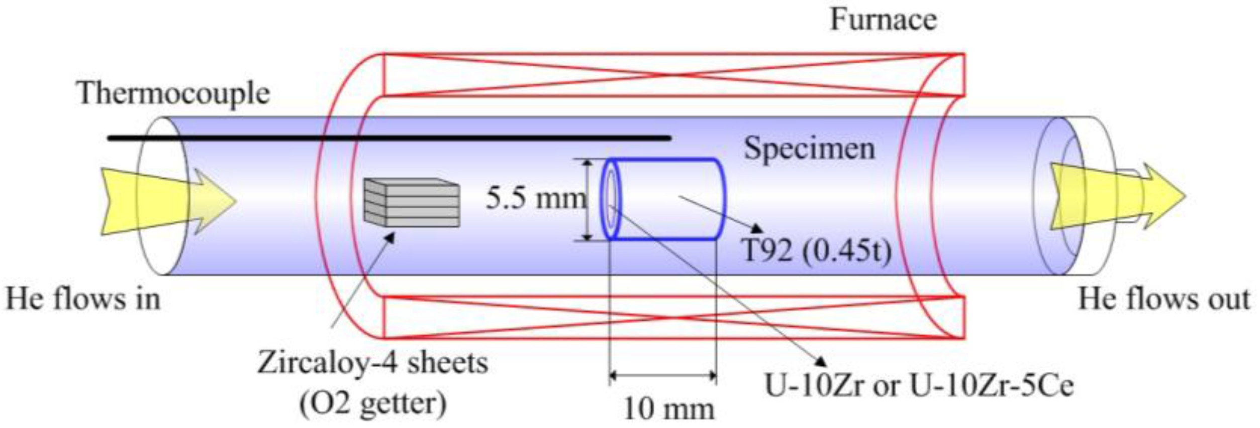
2. Materials and Methods

Heating apparatus for the high-temperature heating test consists of heating tube, furnace, chamber and controller. Schematic diagram of heating tube (JOONGANG VACUUM Co., Ltd., Daejeon, Korea) and furnace (JOONGANG VACUUM Co., Ltd., Daejeon, Korea) is shown in Figure 1. Specifications for the heating apparatus are summarized in Table 1. As for the furnace, electrical resistance heating type is utilized. Considering cladding maximum temperature range (from 650 to 930 °C) and duration time (from tens of seconds to 1.5 days) under transient state for PGSFR (Prototype Gen-IV Sodium-cooled Fast Reactor) which is currently designed in KAERI [9], attainable maximum temperature and duration time with furnace system were designed to be up to at 1200 °C and for two days, respectively. Also, attainable maximum heating rate with furnace system was designed to be 1 °C/s. Furnace body is cooled by a recirculating water coolant. Heating tube (OD: 50 mm, length: 900 mm) is made of 310 stainless steel and length of uniform temperature zone located in the center of heating tube is 150 mm. Specimens are heated in this uniform temperature zone at target temperature during heating test. Heating tube is equipped with inlet/outlet inert helium gas flow line, and Zircaloy-4 sheets which act as O2 getter is inserted in the heating tube. As for the material of chamber, alumina is utilized.
Short segment (length: 10 mm) cut from irradiated fuel rod (fuel slug length: 50 mm, OD: 5.5 mm) which consists of U-10Zr and U-10Zr-5Ce fuel slugs with T92 cladding (thickness: 0.45 mm) [10] (see Figure 2) was heated in the furnace which was located inside of hot cell facility in KAERI. The chemical compositions of as-fabricated U-10Zr and U-10Zr-5Ce fuel slugs, and T92 cladding before irradiation are shown in Table 2 and Table 3, respectively. The peak burnup of irradiated fuel rod was 2.44 at. %. The heating temperature and duration time for U-10Zr/T92 specimen were 750 °C and 1 h, and those for U-10Zr-5Ce/T92 specimen were 800 °C and 1 h. The heating rate from room temperature to target heating temperature was 0.2 °C/s. Heating test conditions are summarized in Table 4. In order to prevent oxidation of test specimens during heating test, inert helium gas was applied to flow through interior of furnace at the flow of 150 ml/min. Also, Zircaloy-4 sheets which act as O2 getter were inserted in the furnace together with test specimens as described above. In the case of heating test without O2 getter, oxidation of test specimen occurred during heating test as shown in Figure 3, so that eutectic melting phenomenon could not be obtained. After completing the heating test with the method preventing oxidation of test specimen, microstructures of test specimen were observed by using the optical microscope (Carl Zeiss Co., Ltd., Seoul, Korea), SEM (SEC Co., Ltd., Suwon, Korea) and EPMA (JEOL Co., Ltd., Seoul, Korea).

3. Results and Discussion

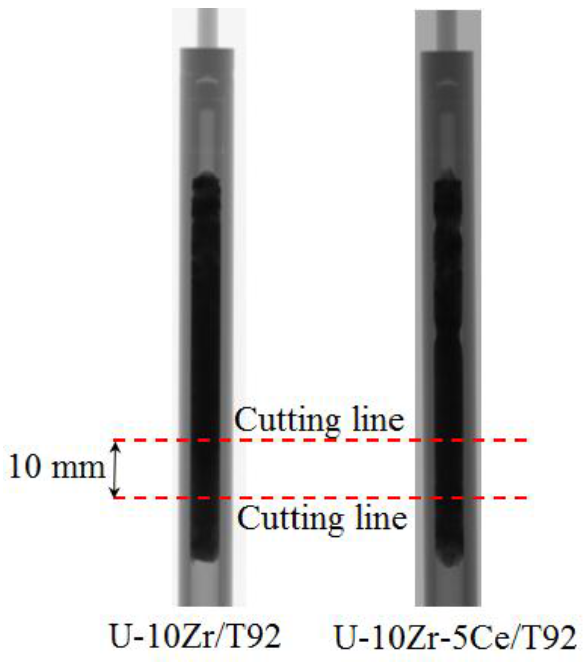
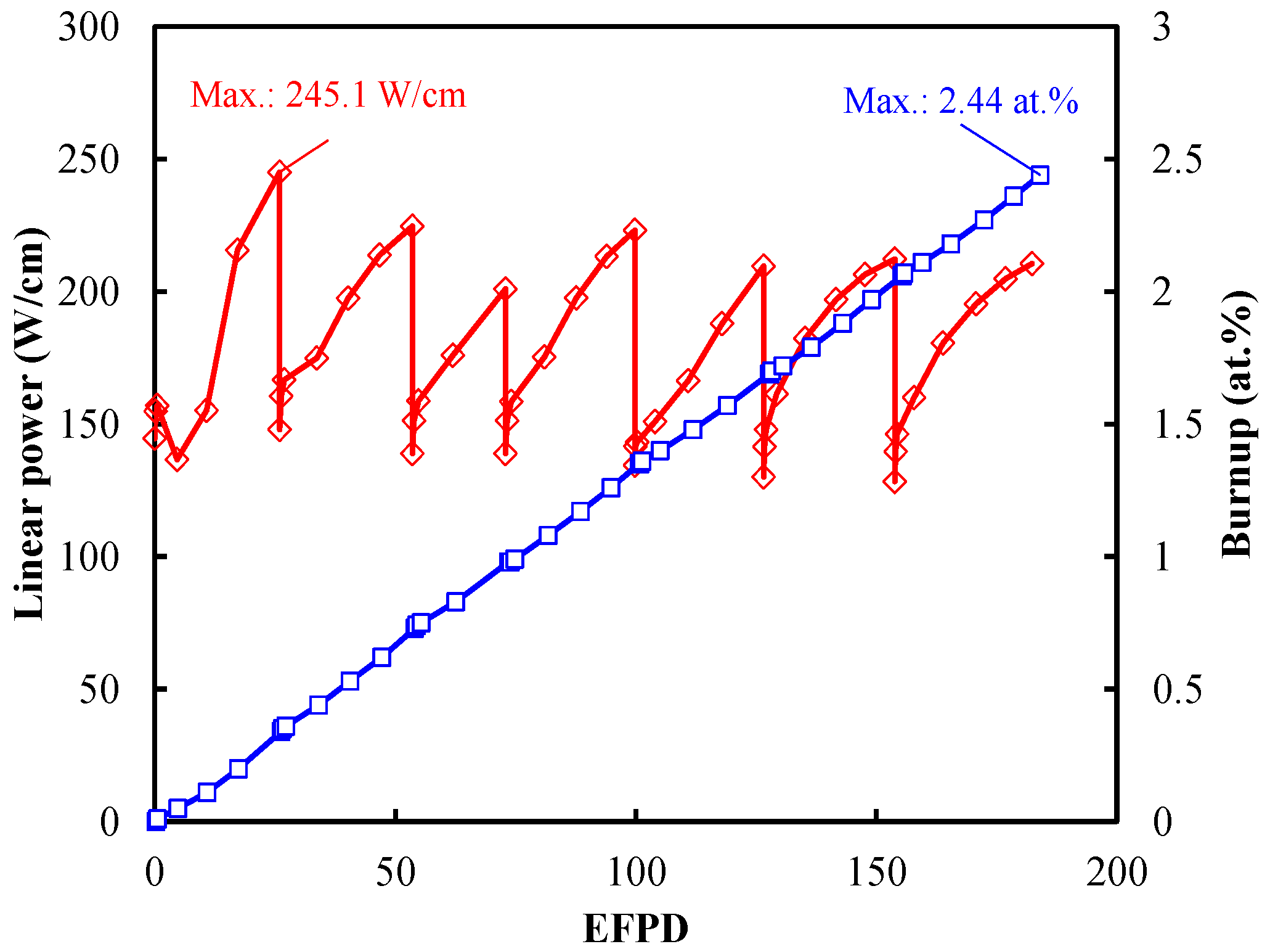
3.1. Irradiation History and PIE (Post-Irradiation Examination) Results

Prior to the explanation of the high-temperature heating test results for the irradiated fuel, the irradiation history and PIE results are briefly described in this section. Detailed explanations of the irradiation history and the PIE results are provided in Reference [10]. The fuel irradiation test was performed for 182 EFPD from 15 November 2010 to 5 January 2012 in HANARO, and subsequently, the irradiated fuel rods were subjected to PIE at IMEF (Irradiated Material Examination Facility). The fuel rod was contained in a sealing tube. Since the operation temperature of HANARO was too low to simulate the actual operating situation of SFR, it was necessary to increase the temperature at the surface of the fuel rod. In order to attain the desirable cladding temperature, a gap has been installed between the fuel rod and sealing tube. The maximum linear power and burn-up were 245.1 W/cm at the beginning of the test and 2.44 at. % at the end of the test according to an as-run analysis (see Figure 4). Using KAERI’s fuel performance analysis code, MACSIS, the maximum cladding inner-wall temperature and fuel centerline temperature were calculated to be 452 °C, and 549 °C, respectively. Therefore, the phases of fuel slugs were irradiated in the α + δ regime as predicted in the U-Zr phase diagram with respect to time and location (see Figure 5). As for U-10Zr/T92, the fuel swelled to make contact with the cladding and there was not enough microstructural evidence in favor of the presence of the fuel-cladding chemical interaction, which was likely to be caused by a low irradiation temperature. In the case of U-10Zr-5Ce/T92, a small gap between the fuel slug and cladding was observed after the irradiation test.
Concentration profiles were measured across the whole cross-section of the fuel and especially around the interface between the fuel and cladding (see Figure 6, Figure 7, Figure 8 and Figure 9). Zr was observed to move against the temperature gradient. The EPMA profile revealed that the Zr distribution was not symmetric with respect to the fuel center, indicating that the cladding was mostly not positioned to be concentric relative to the sealing tube. The distribution of Zr showed a maximum at around the fuel center, and gradually decreased along the fuel surface, which has a lower temperature than the fuel center. Zr migrated toward the higher-temperature side, whose behavior was governed as the Soret effect. In this case, the Soret effect is the sole mechanism for this phenomenon since there was no phase boundary (only the α + δ phase exists) in the fuels. The Nd lanthanide fission product and Ce in the U-10Zr-5Ce fuel were seen to exist near the fuel-cladding interface.

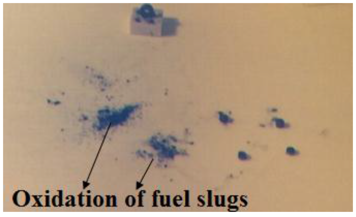
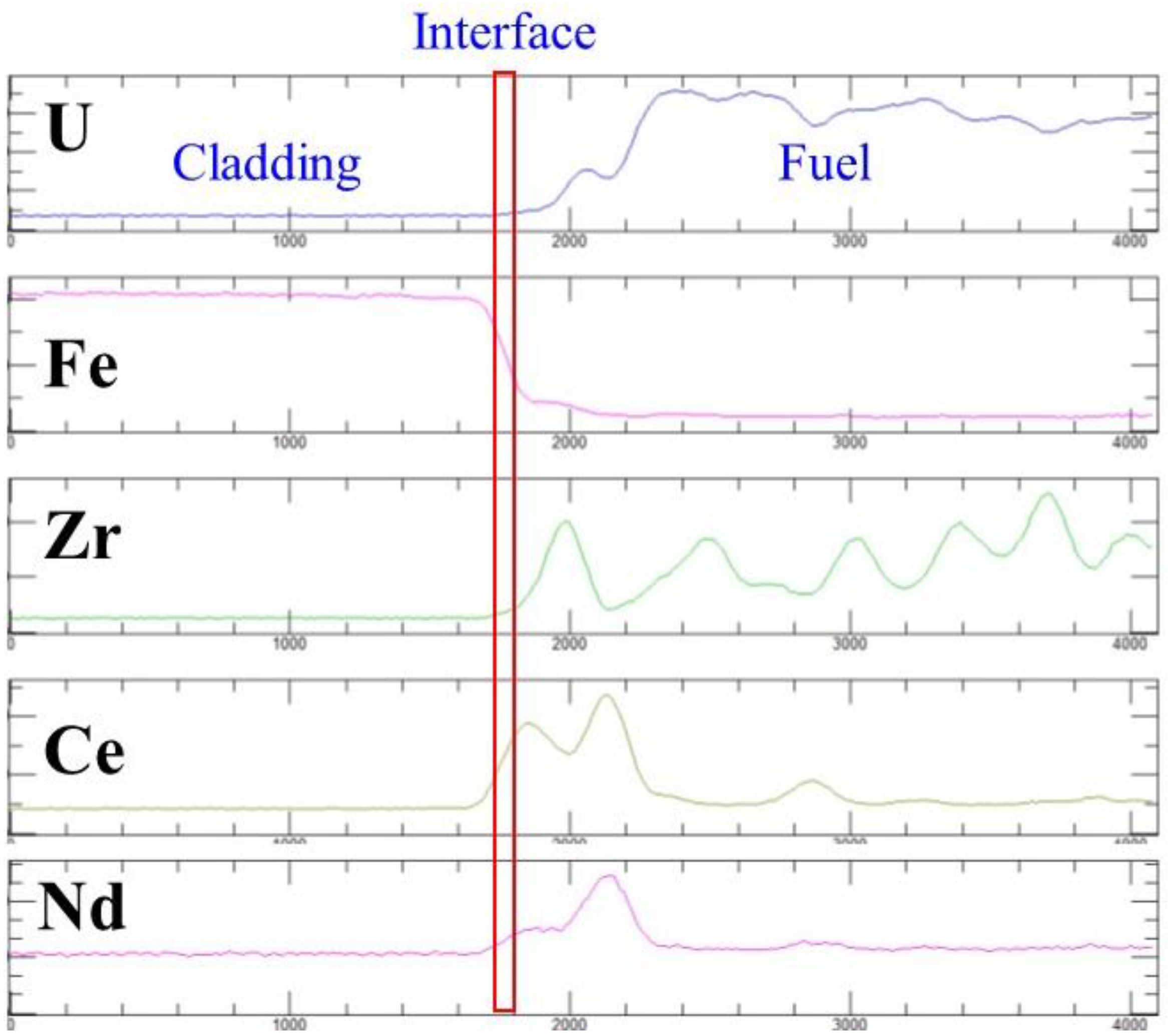
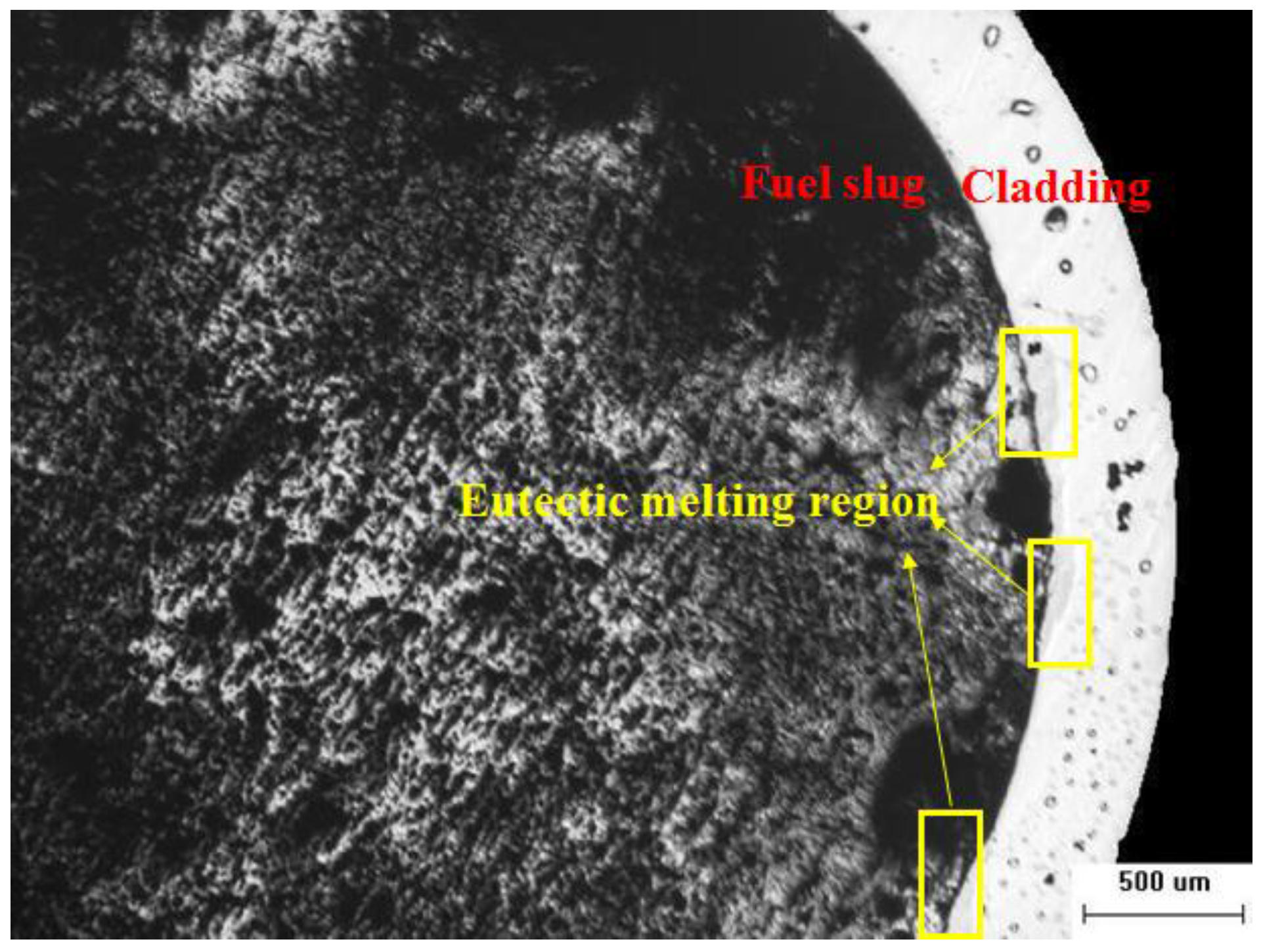
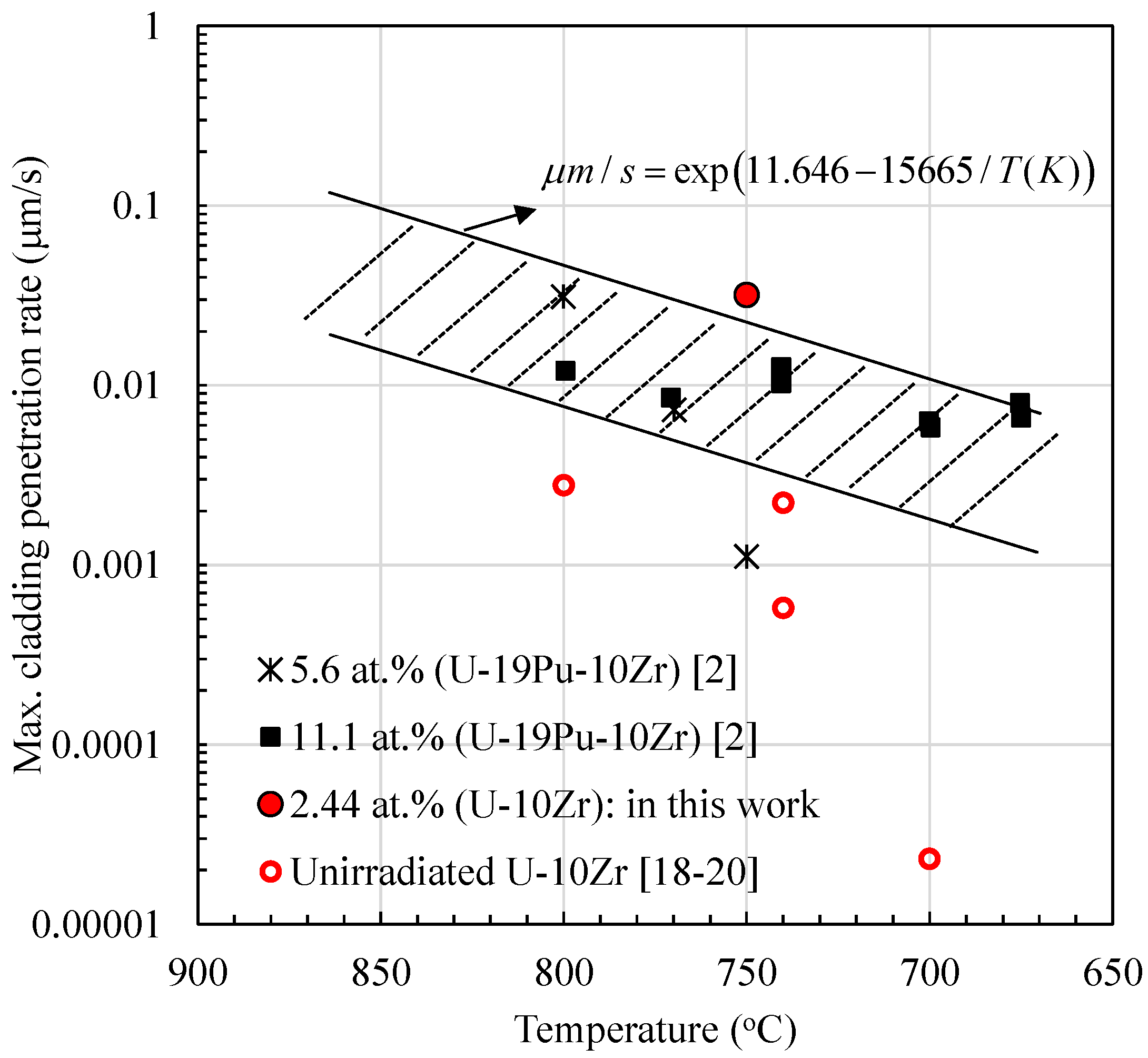
3.2. Results of Irradiated Fuel after High-Temperature Heating Test

Figure 10 and Figure 11 show an optical microscope photograph of the U-10Zr/T92 and U-10Zr-5Ce/T92 specimens after the heating test, respectively. As shown in Figure 10, a eutectic melting region was locally observed in the case of the U-10Zr/T92 specimen. However, in the case of the U-10Zr-5Ce/T92 specimen, a eutectic melting region was not found, because there was a gap between the fuel slug and cladding which originally existed after the irradiation test, and contact between the fuel slug and cladding did not take place during the heating test.
In order to investigate the microstructure of the eutectic melting region in detail for the U-10Zr/T92 specimen, constituent distributions and the eutectic penetration depth were measured by utilizing SEM and EPMA (see Figure 12). As shown in Figure 12, it was observed that the U and Zr components penetrated into the cladding region, and the Fe and Cr components slightly penetrated into the fuel slug region at the eutectic melting region. It was also observed that the Nd lanthanide fission products penetrated into the cladding region. It is reported that the lanthanide fission products such as Nd, Ce, La, Pr, and Sm migrated into the fuel slug–cladding interface during irradiation, and lowered the eutectic threshold temperature, so that, eventually, they promoted the eutectic reaction between the fuel slug and cladding [2,3]. In addition, it is generally known that in the interface region between the fuel and the cladding, the observed phases on both sides in the liquid phase matrix combine the cladding elements Fe and Cr with the fuel components U and Zr [11,12,13] and the lanthanide fission products. As for the cladding-side region of the original fuel-cladding interface, the developed phases are enriched with cladding components and they contain differing amounts of the primary fuel components (U and Zr) and fission product components. In the fuel-side region of the fuel-cladding interaction zone, some phases are observed that are enriched with the fuel constituents U or Zr and contain Fe as the major nonfuel or components with some lanthanides. Other phases are observed that primarily contain lanthanides [2,3,14,15]. Meanwhile, the Zr component in a fuel slug induces stable intermetallic compounds such as ZrFe2, which retards the further development of liquid-phase penetration [16,17].
The measured maximum eutectic penetration depth along the cladding direction during 1 h was 115 µm, and the penetration rate was calculated to be 0.032 μms−1 (115 μm/3600 s). This measured penetration rate is similar to the value (0.026 μms−1) predicted by the existing eutectic penetration rate correlation (Equation (1)) being used for design and modeling purposes [2].
r ˙ = exp ( 11.646 15665 / T )
where r ˙ is the penetration rate (μms−1) and T is the temperature (K). These results are presented in Figure 7 along with the experimental results of the penetration rate with 1 h heating data in the FBTA tests which were reported in the literature [2,3]. In addition, the measured eutectic penetration rates for the unirradiated U-10Zr fuel slug with FMS (ferritic martensitic steel, HT9 or Gr.91) cladding specimens through the out-of-pile heating test which are available in the literature [18,19,20] are also presented in Figure 7. In the case of the heating test for unirradiated fuel with HT9 at 700 °C during 96 h, the measured penetration depth along the cladding direction was approximately 8 μm (penetration rate = 2.3 × 10⁻⁵ μms−1). As for the case of the heating test with HT9 at 740 °C during 96 h, the measured penetration depth was approximately 200 μm (penetration rate = 5.8 × 10⁻⁴ μms−1). Also, as for the case of the heating test with Gr.91 at 740 °C during 25 h, the measured penetration depth was approximately 200 μm (penetration rate = 2.2 × 10⁻³ μms−1). In the case of the heating test with HT9 at 800 °C during 25 h, the measured penetration depth was approximately 250 μm (penetration rate = 2.8 × 10⁻³ μms−1). As shown in Figure 13, the measured eutectic penetration rates for the irradiated fuel specimens are higher than those for the unirradiated U-10Zr specimen. This phenomenon can be caused by the fact that lanthanide fission products migrate into the fuel slug-cladding interface during irradiation and lower the eutectic threshold temperature, so that, eventually, they promote the eutectic reaction between the fuel slug and cladding for the irradiated fuel.

4. Conclusions

Microstructures of the irradiated U-10Zr and U-10Zr-5Ce fuel slugs with T92 cladding after high-temperature heating tests were investigated through an optical microscope, SEM and EPMA. In the case of the U-10Zr/T92 specimen, the migration phenomena of U, Zr, Fe, and Cr as well as the Nd lanthanide fission products were observed at the eutectic melting region. The measured penetration rate was similar to the value predicted by the existing eutectic penetration rate correlation. In addition, when comparing with the measured eutectic penetration rates for the unirradiated U-10Zr fuel slug with FMS (ferritic martensitic steel, HT9 or Gr.91) cladding specimens which are available in the literature, the measured eutectic penetration rate for the irradiated fuel specimen was higher than that for the unirradiated U-10Zr specimen. This phenomenon can be caused by the effect of lanthanide fission product migration into the fuel slug-cladding interface during irradiation, subsequently lowering the eutectic threshold temperature for the irradiated fuel. In the case of the U-10Zr-5Ce/T92 specimen, the eutectic melting region was not found, because there was a gap between the fuel slug and cladding which originally existed after the irradiation test, and contact between the fuel slug and cladding did not take place during the heating test.

Acknowledgments

This project has been carried out under the Nuclear R & D program by Ministry of Science, Ict and Future Planning.

Author Contributions

J.H. Km, J.S. Cheon, B.O. Lee designed the experiments; J.H. Kim contributed to the discussion of results; H.M. Kim, B.O. Yoo, Y.H. Jung and S.B. Ahn performed the experiments; J.H. Kim wrote the paper; C.B. Lee supervised the project.

Conflicts of Interest

The authors declare no conflict of interest.

References

  1. Waltar, A.E.; Todd, D.R.; Tsvetkov, P.V. Fast Spectrum Reactors; Springer: New York, NY, USA, 2012; pp. 3–46. [Google Scholar]
  2. Cohen, A.B.; Tsai, H.; Neimark, L.A. Fuel/cladding compatibility in U-19Pu-10Zr/HT9-clad fuel at elevated temperatures. J. Nucl. Mater. 1993, 204, 244–251. [Google Scholar] [CrossRef]
  3. Tsai, H.; Liu, Y.Y.; Wang, D.Y.; Kramer, J.M. Behavior of low-burnup metallic fuels for the integral fast reactor at elevated temperatures in ex-reactor tests. In Proceedings of the International Conference on Fast Reactor and Related Fuel Cycles, Kyoto, Japan, 28 October–1 November 1991.
  4. Bauer, T.H.; Wright, A.E.; Robinson, W.R.; Holland, J.W.; Rhodes, E.A. Behavior of modern metallic fuel in treat transient overpower tests. Nucl. Technol. 1990, 92, 325–352. [Google Scholar] [CrossRef]
  5. Liu, Y.Y.; Tsai, H.; Billone, M.C.; Holland, J.W.; Kramer, J.M. Behavior of EBR-II Mk-V type fuel elements in simulated loss-of-flow tests. J. Nucl. Mater. 1993, 204, 194–202. [Google Scholar] [CrossRef]
  6. Crawford, D.; Porter, D.L.; Hayes, S.L. Fuels for sodium-cooled fast reactors: US perspective. J. Nucl. Mater. 2007, 371, 202–231. [Google Scholar] [CrossRef]
  7. Tsai, H. Fuel/cladding compatibility in irradiated metallic fuel pins at elevated temperatures. In Proceedings of the International Fast Reactor Safety Meeting, Snowbird, UT, USA, 12–16 August 1990.
  8. Chang, Y.I.; Walters, L.C.; Laidler, J.J.; Pedersen, D.R.; Wade, D.C.; Lineberry, M.J. Integral Fast Reactor Program; Annual Progress Report FY 1993; ANL-IFR-244: Argonne, IL, USA, 1994. [Google Scholar]
  9. Choi, C.; Jeong, T.; Lee, K.; Jeong, J.; Ha, K. Analyses of design extended condition events for the prototype Gen-IV SFR. In Proceedings of the Transactions of the Korean Nuclear Society Autumn Meeting, Gyeongju, Korea, 29–30 October 2015.
  10. Cheon, J.S.; Lee, B.O.; Lee, C.T.; Kim, J.H.; Kim, B.G.; Kim, J.H.; Oh, S.J.; Kim, K.H.; Kim, H.M.; Yoo, B.O.; et al. Post irradiation examination on SMIRP-1 fuel rods. In Proceedings of the Transactions of the Korean Nuclear Nuclear Society Spring Meeting, Jeju, Korea, 29–30 May 2014.
  11. Huang, K.; Park, Y.; Ewh, A.; Sencer, B.H.; Kennedy, J.R.; Coffey, K.R.; Sohn, Y.H. Interdiffusion and reaction between uranium and iron. J. Nucl. Mater. 2012, 424, 82–88. [Google Scholar] [CrossRef]
  12. Huang, K.; Park, Y.; Zhou, L.; Coffey, K.R.; Sohn, Y.H.; Sencer, B.H.; Kennedy, J.R. Effects of Cr and Ni on interdiffusion and reaction between U and Fe-Cr-Ni alloys. J. Nucl. Mater. 2014, 451, 372–378. [Google Scholar] [CrossRef]
  13. Park, Y.; Huang, K.; Puente, A.; Paz, Y.; Lee, H.S.; Sencer, B.H.; Kennedy, J.R.; Sohn, Y.H. Diffusional interaction between U-10 wt. %Zr and Fe at 903 K, 923 K and 953 K. Metall. Mater. Trans. A 2015, 46A, 72–82. [Google Scholar] [CrossRef]
  14. Massalski, T.B. Binary Alloy Phase Diagrams, 2nd ed.; ASM International: Materials Park, OH, USA, 1990. [Google Scholar]
  15. Keiser, D.D., Jr. Comprehensive Nuclear Materials; Elsevier: Waltham, MA, USA, 2012; Chapter 3.15; pp. 435–437. [Google Scholar]
  16. Hofman, G.L.; Hins, A.G.; Porter, D.L.; Leibowitz, L.; Wood, E.L. Chemical interaction of metallic fuel with austenitic and ferritic stainless cladding. In Proceedings of the International Conference on Reliable Fuels for Liquid Metal Reactors, Tucson, AZ, USA, 7 September 1986.
  17. Ogata, T. Comprehensive Nuclear Materials; Elsevier: Waltham, MA, USA, 2012; Chapter 3.01; pp. 33–35. [Google Scholar]
  18. Ryu, H.J.; Lee, B.O.; Oh, S.J.; Kim, J.H.; Lee, C.B. Performance of FCCI barrier foils for U-Zr-X metallic fuel. J. Nucl. Mater. 2009, 392, 206–212. [Google Scholar] [CrossRef]
  19. Yang, S.W.; Ryu, H.J.; Kim, J.H.; Lee, B.O.; Lee, C.B. FCCI barrier performance of electroplated Cr for metallic fuel. J. Nucl. Mater. 2010, 401, 98–103. [Google Scholar] [CrossRef]
  20. Kim, J.H.; Ryu, H.J.; Baek, J.H.; Oh, S.J.; Lee, B.O.; Lee, C.B. Performance of a diffusion barrier under a fuel-clad chemical interaction (FCCI). J. Nucl. Mater. 2009, 394, 144–150. [Google Scholar] [CrossRef]
Figure 1. Schematic diagram of heating tube and furnace.
Metals 06 00278 g001
Figure 2. Short segment (length: 10 mm) cut from irradiated fuel rod (X-ray image).
Metals 06 00278 g002
Figure 3. Oxidation of fuel slugs during heating test without O2 getter.
Metals 06 00278 g003
Figure 4. Linear power and burn-up as a function of EFPD.
Metals 06 00278 g004
Figure 5. Cladding inner-wall temperature and fuel centerline temperature as a function of burn-up.
Metals 06 00278 g005
Figure 6. Concentration profiles (U and Zr) across the whole cross-section of the U-10Zr fuel after irradiation.
Metals 06 00278 g006
Figure 7. Element distribution near fuel (U-10Zr)-cladding interface after irradiation.
Metals 06 00278 g007
Figure 8. Concentration profiles (U, Zr and Ce) across the whole cross-section of the U-10Zr-5Ce fuel after irradiation.
Metals 06 00278 g008
Figure 9. Element distribution near fuel (U-10Zr-5Ce)-cladding interface after irradiation.
Metals 06 00278 g009
Figure 10. Microscope photograph of U-10Zr/T92 specimen after heating test (750 °C, 1 h).
Metals 06 00278 g010
Figure 11. Microscope photograph of U-10Zr-5Ce/T92 specimen after heating test (800 °C, 1 h).
Metals 06 00278 g011
Figure 12. Constituent distributions and eutectic penetration depth of U-10Zr/T92 specimen after heating test (750 °C, 1 h).
Metals 06 00278 g012
Figure 13. Maximum eutectic penetration rate along cladding direction.
Metals 06 00278 g013
Table 1. Specifications for heating apparatus.
Heating UnitSpecification
FurnaceHeating typeElectrical resistance
Maximum temperature (°C)1200
Maximum heating rate (°C/s)1.0
Maximum duration time (day)2
Heating tubeMaterial310 stainless steel
Geometry (mm)OD: 50, Length: 900
Uniform temperature zone (mm)150
ChamberAlumina
Inert gasHe
O2 getterZircaloy-4
Table 2. Chemical composition of as-fabricated U-10Zr and U-10Zr-5Ce fuel slugs.
Fuel SlugZr (wt. %)Ce (wt. %)U-Isotope (wt. %)C (ppm)H (ppm)N (ppm)O (ppm)
U-238U-234U-235U-236
U-10Zr9.8 ± 0.4-80.149 ± 0.0050.17319.551 ± 0.0020.1271102210470
U-10Zr-5Ce11.4 ± 0.45.2 ± 0.280.401 ± 0.0120.17019.303 ± 0.0050.1264502540370
Table 3. Chemical composition (wt. %) of as-fabricated T92 cladding.
CSiMnPSNiCrMoCuAlVWNbBN
0.0870.2050.4120.0120.0020.1268.6860.3810.1040.0060.1840.6180.0660.0020.046
Table 4. High-temperature heating test conditions for irradiated metallic fuel.
Fuel Slug/Cladding MaterialSpecimen Geometry (mm)Temperature (°C)Duration Time (h)Heating Rate from Room Temperature to Target Temperature
LengthOuter DiameterCladding Thickness
U-10Zr/T92105.50.4575010.2
U-10Zr-5Ce/T92800

