Article

The Establishment of Surface Roughness as Failure Criterion of Al–Li Alloy Stretch-Forming Process

1
School of Mechanical and Electrical Engineering, Central South University, Changsha 410083, Hunan, China
2
State Key Laboratory of High Performance Complex Manufacturing, Central South University, Changsha 410083, Hunan, China
3
2011 Collaborative Innovation Center, Central South University, Changsha 410083, Hunan, China
*
Author to whom correspondence should be addressed.
Metals 2016, 6(1), 13; https://doi.org/10.3390/met6010013
Submission received: 17 December 2015 / Revised: 25 December 2015 / Accepted: 28 December 2015 / Published: 7 January 2016
(This article belongs to the Special Issue Aluminum Alloys)

Abstract

:
Taking Al–Li–S4–T8 Al–Li alloy as the study object, based on the stretching and deforming characteristics of sheet metals, this paper proposes a new approach of critical orange peel state characterizations on the basis of the precise measurement of stretch-forming surface roughness and establishes the critical criterion for the occurrence of orange peel surface defects in the stretch-forming process of Al–Li alloy sheet metals. Stretching experiments of different strain paths are conducted on the specimens with different notches so as to establish the Al–Li–S4–T8 Al–Li alloy, forming limit diagram and forming limit curve equation, with the surface roughness of characteristic critical orange peel structure as the stretch-forming failure criterion.

Graphical Abstract

1. Introduction

Aircraft skin serves as the shape part of an aircraft and constructs the aerodynamic configuration of the aircraft, featuring big size and direct contact with air. Therefore, it requires an accurate shape, smooth streamline, and no surface defects, etc. [1]. As a relatively common aircraft skin-forming approach in the field of aeronautics and astronautics manufacturing, the technology of stretch-forming is widely used in the manufacturing of large-scale aircraft skin as part of aircraft aerodynamic configuration [2,3,4]. In the stretch-forming process, the clamps of the stretch-forming machine clamp both ends of the sheet metal and move along a certain track, or the die goes up to make the sheet metal contact the stretch-forming die, creating uneven plane stretching strain to make the metal sheet conform to the stretch-forming die so as to obtain the required part shape [5,6,7]. Compared with other approaches to aircraft skin forming, the stretch-forming technology might cause surface defects such as orange peel. Orange peel not only affects the appearance of the aircraft skin, but also damages its surface integrity. Especially in the case of mirror skin, orange peel easily appears due to mirror skin’s internal structure and polished surface, seriously affecting its service life, which is usually the main reason for the scrapping of parts [8].
The defect of orange peel is a kind of rough orange peel-like morphology found on the surface of shaped products. In general, coarse and unevenly structured grains on the alloy surface are considered the reason of the orange peel defect appearing on the alloy surface during the stretch-forming process, while the grain size of the alloy has a certain relation to the extent of the deformation. At a certain temperature, when there are relatively small deformations, recrystallization usually does not appear in the alloy and the grains maintain their original state; however, when deformation reaches a certain degree, recrystallized grains will become very coarse. In the manufacturing process of aluminum alloy skin sheet metal, there are usually multiple hot rolling and cold rolling processes as well as several heat treatments including annealing, solution and aging. Because of the imperfection in the control over cold deformation and the choice of heat treatment technology in the manufacturing process of aluminum alloy sheet metal, recrystallized grain structure tends to be coarse and show different sizes, resulting in the piling up of dislocation on large grains and the rapid increases of stress in the follow-up stretch-forming process. Thus, the areas of large grains reach and exceed the elastic limit in advance; the non-synchronous deformation between large grains and small ones gives rise to minor cracks on the surface of the material, manifesting as the orange peel structure at the macro-level [9].
The forming limit of sheet metal is a criterion used to describe whether the sheet metal fails to form or not. To identify the concept of forming limit, one should first determine the failure criterion of sheet metal’s forming process. Al–Li alloy as a new type of aluminum alloy has shown a wide application prospect in the fields of aeronautics and astronautics due to its good qualities of low density, high specific strength, and high specific stiffness, and it has become a hot subject in the research field of aluminum alloy materials, being regarded as one of the important candidate materials of modern aeronautic and astronautic structures [10,11]. However, due to the high cost, poor cold plasticity at ambient temperature, evident anisotropy and easy cracking in cold working compared with other regular aluminum alloys, Al–Li alloy at present can only be processed into relatively simple parts and faces great difficulty in the processing and manufacturing of more complex structural parts. Therefore, some of its own attributes also limit Al–Li alloy’s application in structural components [12,13,14,15]. Relevant researchers have conducted corresponding research on the formability of Al–Li alloy, which, however, mainly focus on the study of the Al–Li alloy’s structure property and the aspect of hot forming. Literature [16] explored the 2397-T87 Al–Li alloy with a thickness of 130 mm for the microstructure, stretching property and fracture toughness of layers with different thicknesses and at different orientations. By the uniaxial tension test under different hot deformation conditions, the forming limit test with cracking as a failure criterion, and the stretch-forming tests of 5A90 Al–Li alloy sheet metal, literature [17] built the Al–Li alloy forming limit model and determined the technological parameters for Al–Li alloy to acquire good deformation performance.
Nevertheless, for aviation aircraft skin materials, cracking is not often taken as the criterion for judging whether the skin fails to form or not, especially for Al–Li alloy, the reason of which usually lies in that the forming failure is caused by the appearance of orange peel structure in the stretch-forming process. Currently, there are relatively few studies on the forming limit caused by the defect of orange peel in the stretch-forming process, and a forming failure criterion targeting the orange peel has not yet taken shape. As the occurrence of the orange peel phenomenon is a slowly changing and accumulated process, and all of the previous research on such a phenomenon was conducted by eye measurement, the results have certain randomness.
In this paper, experimental research on the problem of orange peel in the stretch-forming process of Al–Li alloy is conducted, and a novel approach of critical orange peel characterization is proposed on the basis of the precise measurement of stretch-forming surface roughness. Furthermore, the judgment criterion of the orange peel defect is analyzed and established, the stretching tests on specimens of different strain paths are conducted combining the technology of optical deformation measurement, and, ultimately, the stretch-forming limit diagram and its forming limit curve equation are obtained with the surface roughness of orange peel structure with critical characteristics such as the stretch-forming failure criterion.

2. Experiments

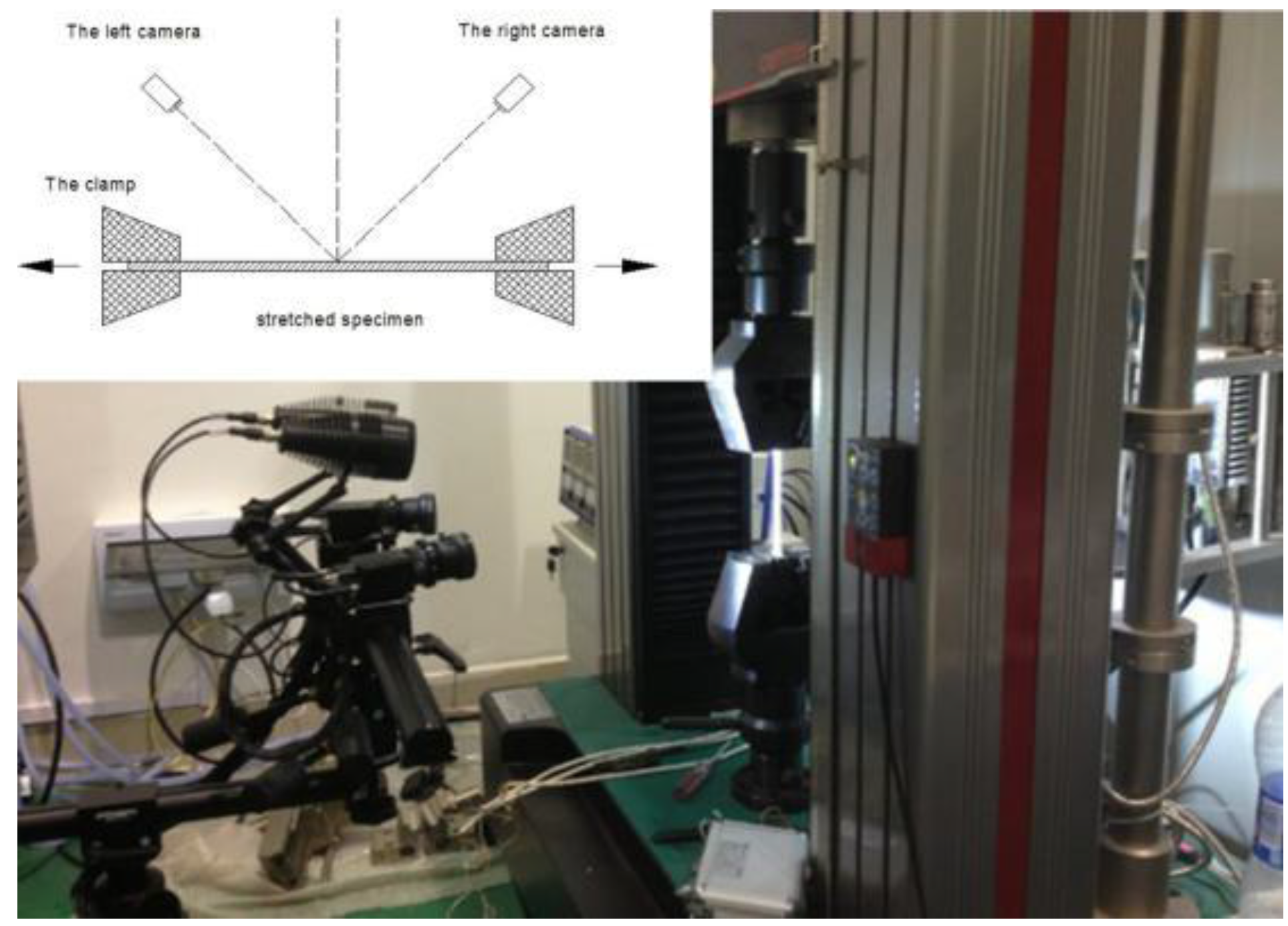
2.1. Instrument and Methods

In order to conduct synchronization tests on stress-strain and orange peel surface defect in the stretch-forming process of Al–Li alloy, a stretch-forming test and testing system are established to obtain the critical strain state of orange peel of the product, in which the optical deformation measurement instrument and the universal testing machine operate in collaboration, as shown in Figure 1.
The optical deformation measurement instrument used in the experiment adopts the deformation measurement system based on computer vision technology developed by the German company GOM for three-dimensional deformation analysis. By controlling the synchronized operation of the optical deformation measurement instrument and the universal testing machine, the complete monitoring of the total stretch-forming deformation process of the specimens can be achieved and the computer image processing system can be further utilized to obtain the true strain change rules at different positions on the specimen surface throughout the stretch-forming process.
Figure 1. The stretching and testing system.
Metals 06 00013 g001
Compared with the stretch-forming mechanism, this experimental mechanism is to some extent simplified, in particular with the top die removed. However, in the actual stretch-forming process of the sheet metal, with the stretch-forming die going up, the sheet metal gradually bends to attach to the die as shown in Figure 2. Due to the existence of friction, the material flow of the attaching segment AA′ tends to be limited to a relatively small deformation, whereas the free segments without contact with the die AB and A′B′ tend to have relatively greater deformation without the restriction of friction. Therefore, the orange peel structure usually appears first on the free segments between the chucks and the die corners, and then slowly spreads toward the forming surface that attaches to the die. Thus, it can be seen that the deformation of the free segments on the sheet metal is the principal factor affecting the appearance of orange peel structure. As the deformation of the free segments on the sheet metal is similar to its stretch-forming, the conventional stretching test of sheet metal can be used in the research on the influence of the orange peel phenomenon on the stretch-forming of the materials.
Figure 2. The schematic diagram of stretch-forming die.
Metals 06 00013 g002

2.2. Experimental Design

2.2.1. Experiment Design of Critical State Criterion of Orange Peel Defect

The experimental material was the Al–Li–S4–T8 Al–Li alloy which was used for aircraft skin with a thickness of 2 mm. See Figure 3 for the structure and size of the stretched specimens. The experimental specimens were polished to make the surfaces bright and without obvious scratches.
Meanwhile, in order to establish the same initial surface state for all specimens, the roughness of polished specimens was measured on the optical surface profilometer to ensure similar polishing effects for all the specimens.
Figure 3. The shape and size of stretched specimen.
Metals 06 00013 g003
Stretching tests of different strains were conducted on polished specimens to investigate the evolution situation of the orange peel phenomenon on material surfaces under the condition of different deformations. See stretching strains in Table 1. Additionally, tests were also conducted at four different strain speeds on T8 alloy to investigate the impacts of different deforming speeds on the orange peel phenomenon on specimen surfaces in the experiment. By contrasting the surface morphology and true strain of the specimen at different speeds, when tiny orange peel phenomena appear on the surface at different strain speeds, the true strain of the Al–Li–S4–T8 Al–Li alloy metal sheet can be measured with the results shown in Table 2. It is observed from the table that when the strain speed is 0.0005/s, the strain at the sampling point is the greatest when tiny orange peel structure on the specimen surface appears. Thus, in actual stretch-forming treatment of aircraft skin, the said speed can be employed to alleviate the appearance of the orange peel phenomenon.
Table 1. Stretching strains of samples.
Experiment Batch No.12345
Stretching Strain0%3%6%9%12%
Table 2. Critical strain and roughness of samples.
Specimen No.Strain Speed/s−1Critical Strain/%Roughness Ra/nm
10.00011.78841
20.00051.87827
30.0011.14973
40.00151.191002
After the stretching tests, both sides of the specimens were cleaned again, and the side used for surface morphology observation was placed under the optical profilometer for surface analysis, obtaining the morphology, nephogram and roughness of the specimen surfaces. Combined with the criterion of the orange peel defect obtained by the experiment, the areas in which critical orange peel structure occurred were found on the specimens, and the strain state of the areas can be also found at the same positions on the other side of the specimens, which actually is the critical strain state of the appearing orange peel defect.

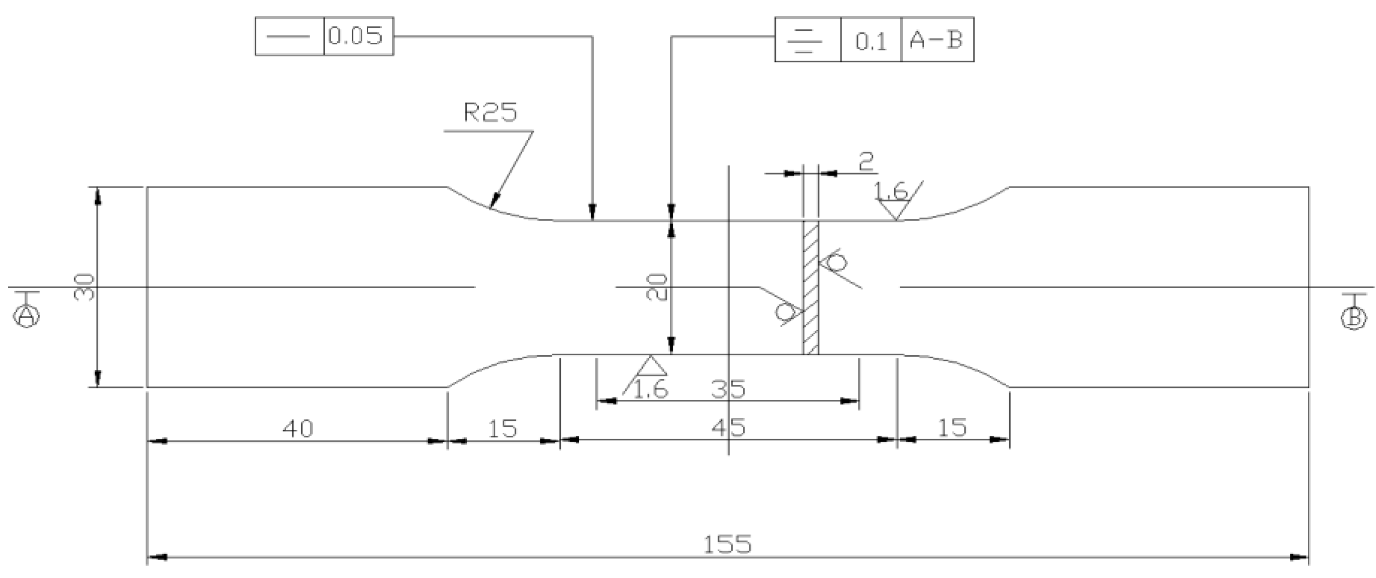
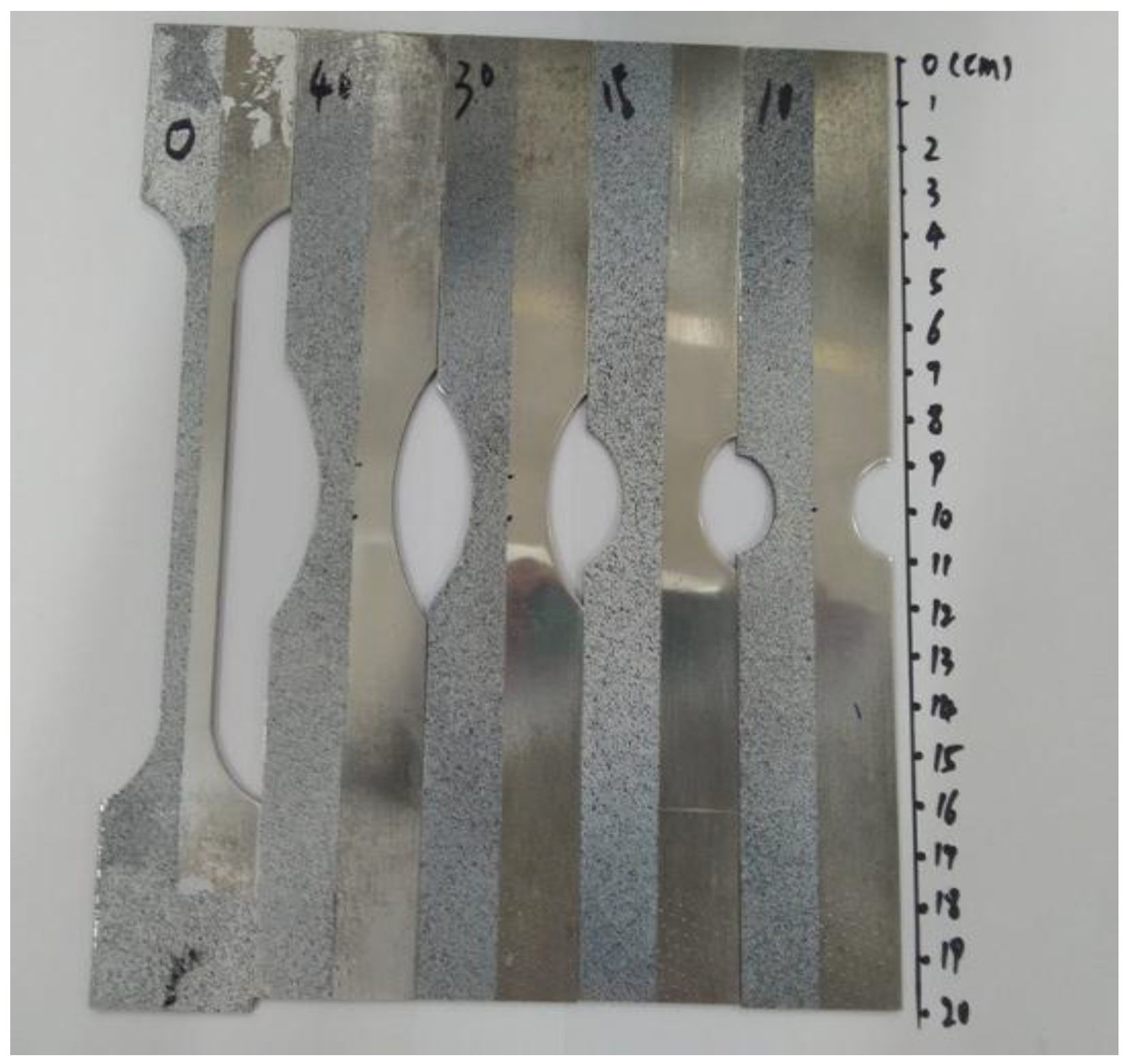
2.2.2. Experiment Design of Stretch Forming Limit Diagram

During the stretch-forming process of aircraft skin, the strain state of sheet metals mainly fell between uniaxial stretching and plane strain with approximately linear strain paths [18]. Thus, stretch-forming specimens that could implement different strain paths were designed with the typical specimen structure and size given in Figure 4, among which the straight-edge stretched specimen was close to the uniaxial stretching state of strain, while the R = 10 notched specimen was close to the plane state of strain [19].
Figure 4. Size of samples with different strain paths.
Metals 06 00013 g004
In order to conduct observation and analysis of the surface morphology and strain state of the specimens, both sides of the specimens were polished until without an obvious scratch, and a profilometer was used to measure the surface roughness to achieve similar polishing effects for each specimen. The specimens with ethanol were cleaned after polishing. As shown in Figure 5, the black and white speckle patterns were sprayed on half of one side of the specimens, so as to analyze the true strain on specimen surfaces during the stretching process; another half was used to observe the evolvement of the orange peel phenomenon on specimen surfaces during the stretching process. Meanwhile, another side, only polished, was used to measure surface morphology and roughness with the profilometer.
Figure 5. Sample appearances along different strain paths after surface treatment.
Metals 06 00013 g005

3. Results and Analysis

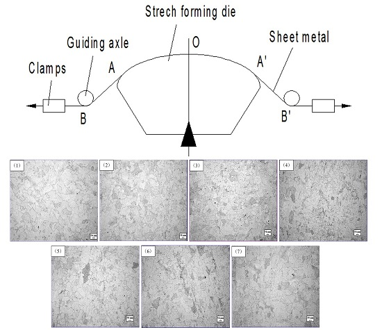
3.1. The Equilibrium Diagram of Tensile Specimen before Deformation

The grain size grade of the specimen can be measured in accordance with the Metal Methods for Estimating the Average Grain Size, as shown in Table 3 below. From the measured grain size grades, as shown in Figure 6 and Figure 7, it is observed that the average grain size of the specimen is 60–80 μm, suggesting that the specimen has already fallen into the category of open grain structure. Meanwhile, judging from the equilibrium diagram, the grain structure of the specimen is extremely uneven with a large difference in size between the large grains and small grains. It is also discovered from the measurement that the size of the large grains is over 100 μm, but that of the small ones is merely around 10 μm. Thus, the equilibrium diagram can explain the appearance of orange peel in the process.
Figure 6. The exact location on the sample.
Metals 06 00013 g006
Figure 7. The equilibrium diagram of tensile specimen before deformation. (1) is correspondence with 1 in Figure 6; (2) is correspondence with 2 in Figure 6; (3) is correspondence with 3 in Figure 6; (4) is correspondence with 4 in Figure 6; (5) is correspondence with 5 in Figure 6; (6) is correspondence with 6 in Figure 6; (7) is correspondence with 7 in Figure 6.
Metals 06 00013 g007
Table 3. Grain size analysis of tensile specimen.
Heat Treatment ConditionType of AnalysisSampling PointAverage
1234567
T8Grain Size Grade5.025.134.514.384.984.624.564.7
Average Diameter/µm6259767770757571

3.2. The Establishment of the Criterion for Critical State of Orange Peel Defect

The specimens were cleaned after stretch processing with ethanol, and surface observation and analysis on the optical profilometer were conducted. The photographed morphology can be seen in Figure 8, which shows that when the strain is 3%, the specimen surface starts to grow rough and form a kind of evenly frosted surface morphology, but without evident minor cracks or significant orange peel phenomenon; when the strain reaches 6%, light black strip areas appear on the surface, which are shallow grooves, and an embryonic form of orange peel structure can be roughly observed. When the strain reaches 9%, there are clear cracks appearing on the specimen surface, which is rather severe despite the fact that they are relatively decentralized and independent; at the macro-level, a very significant orange peel phenomenon is manifested. At this stage, the orange peel structure on the material surface not only affects the appearance of the stretch-forming parts, but also exerts great influence on the performance and service life of the specimen, whereas the minor cracks on the surface can easily give rise to stress concentration and gradually evolve into greater cracks after stress. When the strain amounts to 12%, the surface morphology of the specimen further deteriorates with more and deeper cracks, having already formed gully-like shapes.
Figure 8. Surface morphology of stretched specimens with different strain variables: (a) 0%; (b) 3%; (c) 6%; (d) 9%; (e) 12%.
Metals 06 00013 g008
It can be seen from the analysis results that when the strain reaches around 6%, the specimen surface starts to form the orange peel defect in a real sense, but as the gap between the strain variables is relatively large, it is impossible to determine that the specimen is in the critical orange peel state when the strain is 6%. Thus, on the basis of the previous research, strain variables of 5% and 7% were added to a new test to observe their surface morphology after stretching, with the results given in Figure 9. When the strain was 5%, the specimen surface had not yet formed clear grooves, but through comparing the stretched specimens of 6% and 7%, it could be found that, though with roughly the same surface morphology, the scanning image of the stretched specimen with 7% strain clearly showed darker grooves with relatively deep cracks starting to develop.
Figure 9. Surface morphology of stretched specimens with different strain variables: (a) 5%; (b) 6%; (c) 7%.
Metals 06 00013 g009
On this basis, the roughness of specimen surfaces with different strain variables is measured, the results of which are as shown in Figure 10, where Ra is the arithmetic mean of the absolute value of the distance between the dot on the profile and the baseline; Rq is the root mean square error of the profile, i.e., the root mean square value of the profile’s offset distance within the sampling range; Rz is the micro-irregularity on the material surface, i.e., the sum of the average of the five greatest profile peaks and the average of the five smallest profile valleys within the sampling length. Combined with the surface morphology measured by the profilometer, it can been seen that, at the stage of 0%~5% strain, the main change was that the specimen surface began to wrinkle, with dispersed convexes and concaves appearing as well as a rapid change of surface roughness; at the stage of 5%~6% strain, there was little change in the surface roughness, but dispersed convexes and concaves started to gather to form lumps while grooves appeared and started to develop into cracks, which is also the major stage of qualitative change appearing on the material surface; at the stage of 6%~12% strain, cracks rapidly developed, gradually grew deeper, and joined with each other to form the gully-like morphology, resulting in the rapid increase in Rz of the specimens.
Figure 10. Changing trend of stretched sample surface roughness.
Metals 06 00013 g010
Based on the above experimental analyses, it can be assumed that when a morphology similar to that of the stretched specimen with 6% strain appears on the specimen surface, the orange peel phenomenon comes to a critical state. Thus, a roughness of Ra = 700 ± 50 nm and Rz = 5.5 ± 0.5 μm can be taken as a reference standard for judging whether the orange peel structure on a material surface reaches a critical state.

3.3. The Establishment of Stretch-Forming Limit Diagram

On the basis of obtaining the corresponding strain state and surface roughness of the orange peel structure on the standard specimens, the research on the stretch-forming limit under different strain paths is further conducted, through which strain data of different strain paths is measured with the surface roughness of the characteristic critical orange peel structure as the forming failure criterion, as shown in Table 4.
Table 4. Strain state of critical orange peel structure of specimens under different strain paths.
SampleAcquisition Point 1Acquisition Point 2Acquisition Point 3Acquisition Point 4Acquisition Point 5
ε1/%ε2/%ε1/%ε2/%ε1/%ε2/%ε1/%ε2/%ε1/%ε2/%
Straight edge6.29−1.946.35−1.986.31−2.086.25−1.846.33−1.88
R = 103.17−0.213.17−0.182.65−0.152.76−0.133.17−0.15
R = 152.95−0.193.04−0.133.27−0.123.31−0.233.09−0.08
R = 303.31−0.553.76−0.583.64−0.773.72−0.573.30−0.55
R = 404.49−1.204.82−1.594.66−1.273.92−1.044.20−1.23
Quadratic-multinomial fitting is conducted on measured data so as to establish the forming limit diagram of the orange peel phenomenon on the aluminum alloy surface with the results shown in Figure 11 and the quadratic-multinomial fitting results given in Table 5. It can be seen from the figure that the orange peel structure on the aluminum alloy surface is correlated with the strain state of the materials; meanwhile, the materials at the plane state of strain more easily develop orange peel structure than those at the uniaxial stretching strain state.
Table 5. Binomial fitting results.
ExpressionABC
y = A + Bx + Cx22.99−0.3890.652
Figure 11. Stretch-forming limit diagram of Al–Li alloy at the condition of Al–Li–S4–T8.
Metals 06 00013 g011

4. Conclusions

(1)
A stretch-forming experiment and testing system with the optical deformation measurement instrument and the universal testing machine operating in collaboration are constructed, the surface morphology change rule of stretched specimens with different strain variables is analyzed, and the corresponding relation between critical orange peel defect and the surface roughness of specimens is obtained. It is discovered that when critical orange peel defect appears on Al–Li alloy sheet metal at the condition of Al–Li–S4–T8, the surface roughness is Ra = 700 ± 50 nm and Rz = 5.5 ± 0.5 μm.
(2)
By processing different notched specimens, the stretch-forming limit tests with different strain paths are conducted to obtain the forming limit diagram and forming limit curve equation ε1 = 2.99 − 0.389ε2 + 0.652ε22 for Al–Li–S4–T8 Al–Li alloy, with the surface roughness of characteristic critical orange peel structure as the forming failure criterion.

Acknowledgments

This research was financially supported by the National Basic Research Program of China (2014CB046602) and the National Natural Science Foundation of China (51235010).

Author Contributions

Jing-Wen Feng and Li-Hua Zhan conceived and designed the experiments; Jing-Wen Feng and Ying-Ge Yang performed the experiments; Jing-Wen Feng analyzed the data; Jing-Wen Feng wrote the paper.

Conflicts of Interest

The authors declare no conflict of interest.

References

  1. Wang, K.; Wan, M.; Hua, C.; Shao, X.F. Determination and application of coarse-grain critical pre-strain curve to aluminum alloy stretch forming. J. Beijing Univ. Aeronaut. Astronaut. 2013, 39, 508–511. [Google Scholar]
  2. Han, Z.R.; Dai, L.J.; Zhang, L.Y. Current status of large aircraft skin and panel manufacturing technologies. Aeronaut. Manuf. Technol. 2009, 25, 64–66. [Google Scholar]
  3. Araghi, B.T.; Manco, G.L.; Bambach, M.; Hirt, G. Investigation into a new hybrid forming process: Incremental sheet forming combined with stretch forming. CIRP Ann. Manuf. Technol. 2009, 58, 225–228. [Google Scholar] [CrossRef]
  4. Kurukuri, S.; Miroux, A.; Wisselink, H.; Boogaard, T.V.D. Simulation of stretch forming with intermediate heat treatments of aircraft skins: A physically based modeling approach. Int. J. Mater. Form. 2011, 4, 129–140. [Google Scholar] [CrossRef]
  5. General Editorial Board of “The Manual of Aeronautical Manufacturing Engineering”. In The Aviation Manufacturing Engineering Handbook—Aircraft Sheet Metal Process; Aviation Industry Press: Beijing, China, 1992.
  6. Hu, S.G.; Chen, H.Z. Manufacturing Technology of Aircraft Sheet Metal Parts; Beijing University of Aeronautics and Astronautics Press: Beijing, China, 2004. [Google Scholar]
  7. Chang, R.F. Sheet Metal Parts Manufacturing Technology; National Defence Industry Press: Beijing, China, 1992. [Google Scholar]
  8. Wan, M.; Zhou, X.B.; Li, X.X.; Wu, H. Process parameters in stretch forming of mirror skins. Acta Aeronaut. Astronaut. Sin. 1999, 20, 326–330. [Google Scholar]
  9. You, Z.H.; Huang, Y.S.; Wu, R.H. A study of orange-like roughness on front side on Airplane. Aviat. Maint. Eng. 2001, 6, 46–47. [Google Scholar]
  10. Zhang, R.X.; Zeng, Y.S. Development, technological characteristics and application status abroad of aluminum-lithium alloys (In Chinese). Aeronaut. Manuf. Technol. 2007. [Google Scholar] [CrossRef]
  11. Yin, D.F.; Zheng, Z.Q. History and current status of aluminum-lithium alloys research and development. Mater. Rev. 2003, 17, 18–20. [Google Scholar]
  12. Huo, H.Q.; Hao, W.X.; Geng, G.H.; Da, D.A. Development of the new aero-craft material—Aluminum–lithium alloy. Vac. Low Temp. 2005, 11, 63–69. [Google Scholar]
  13. Lyttle, M.T.; Wert, J.A. The plastic anisotropy of an Al–Li–Cu–Zr alloy extrusion in unidirectional deformation. Metall. Mater. Trans. A 1996, 27, 3503–3512. [Google Scholar] [CrossRef]
  14. Li, H.; Tang, Y.; Zeng, Z.; Zheng, Z.; Zheng, F. Effect of ageing time on strength and microstructures of an Al–Cu–Li–Zn–Mg–Mn–Zr alloy. Mater. Sci. Eng. A 2008, 498, 314–320. [Google Scholar] [CrossRef]
  15. Huang, J.C.; Ardell, A.J. Addition rules and the contribution of δ′ precipitates to strengthening of aged Al–Li–Cu alloys. Acta Metall. 1988, 36, 2995–3006. [Google Scholar] [CrossRef]
  16. Fan, C.P.; Zheng, Z.Q.; Jia, M.; Zhong, J.F.; Cheng, B.; Li, H.P.; Wu, Q.P. Microstructure, tensile property and fracture toughness of 2397 Al–Li alloy. Rare Met. Eng. 2015, 44, 91–96. [Google Scholar]
  17. Ma, G.S. Hot Forming Technology of Complex Aluminum Lithium Alloy Parts; Chemical Industry Press: Beijing, China, 2011. [Google Scholar]
  18. Jin, H.X. Basic Experimental Research and Simulation on Aluminum Alloy Mirror Skin Tensile Forming; Beijing University of Aeronautics and Astronautics: Beijing, China, 2009. [Google Scholar]
  19. Wan, M.; Han, J.Q.; Jin, H.X.; Wu, H. Determination of strain criterion of portevin–Le chatelier effect for aluminum alloy sheets. Trans. Nonferrous Met. Soc. China 2006, 16, 1499–1503. [Google Scholar]

