Article

Characteristics of Oxide Films on Zr702 and Their Corrosion Performance in Boiling Fluorinated Nitric Acid

1
State Key Laboratory of Solidification Processing, School of Material Science and Engineering, Northwestern Polytechnical University, Xi’an 710072, China
2
Xi’an QinTi Intelligent Manufacturing Technologies Co., Ltd., Xi’an 710016, China
3
State Key Laboratory of Porous Metal Materials, Northwest Institute for Non-Ferrous Metal Research, Xi’an 710016, China
4
Xi’an Rare Metal Materials Institute Co., Ltd., Xi’an 710016, China
*
Authors to whom correspondence should be addressed.
Metals 2024, 14(4), 479; https://doi.org/10.3390/met14040479
Submission received: 18 March 2024 / Revised: 11 April 2024 / Accepted: 17 April 2024 / Published: 19 April 2024

Abstract

:
Fluoride ions, which interfere with the oxide formation on zirconium have been over-looked until recently. The effect of fluoride ions on oxide formation and dissolution behaviors in zirconium was investigated in this study. A detailed quantitative characterization of the oxide films formed on Zr702 immersed in a fluorinated nitric acid solution was performed using X-ray photoelectron spectroscopy, high-resolution transmission electron microscopy, and representative high-angle annular dark-field scanning Transmission Electron Microscope, (TEM). The corrosion performance in a fluorinated nitric acid solution was discussed. The results reveal that the thickness of the oxide films immersed in the fluorinated nitric acid solution was between 42–48 nm, which is much thinner than that of the oxide layer (~98.85 nm thickness) in the F free HNO3 solution. The oxide film was identified to be a nanocrystalline cluster, comprised of outermost HfO2 and HfF4 layers, sub-outer ZrO2 and ZrF4 layers, and an innermost Zr (F, O)3.6 layer. This fluoride species penetration through the oxide films indicated that the fluoride ions are responsible for the dissolution of the oxide film of Zr702.

1. Introduction

Zirconium base alloy (Zr alloy) is a key material in the nuclear industry due to its thermal stability, mechanical durability, and low thermal neutron cross-section. However, corrosion can seriously affect its integrity and service life. The corrosion resistance of zirconium stems from the passive oxide films on its surface. The oxide film is most likely zirconium dioxide (ZrO2), a compound closer to insulators than semiconductors. The chemical bonding between zirconium and oxygen is extremely strong, and as the oxide film grows, the current will flow through the film with increasing difficulty [1,2,3,4,5]. ZrO2 retains most of its corrosion protection ability when its pH is less than 1 and above 13. Zirconium is one of the few metals that exhibits excellent corrosion resistance over a wide range of pH levels, and thus, it can be used in processes that cycle between strong acids and strong alkalis. However, when zirconium is placed in a nitric acid solution containing fluoride ions, its passive oxide films will start to dissolve [6,7,8,9,10].
Hlawka et al. reported that the dissolution rate of zirconium in hydrofluoric acid depends only on acid concentration but that the properties of the oxide film on zirconium are determined by the nature of the strong acid added to hydrogen fluoride [11]. According to the authors, extremely high corrosion rates were observed for Zr-4 coupons in a fluorinated nitric acid medium.
Zulai Li et al. [12]. investigated the corrosion behavior of industrial reactor materials Ti (TA2) and Zr (ZR-1) under acidic conditions (20 vol%H2SO4 or 20 vol% HNO3 solutions). The results showed that in 20 vol%HNO3 solution, the corrosion rate of Zr increases 120 times when the solution is heated to 200 °C.
Zhang wei jia Qiu recently demonstrated the formation of a dense Na3ZrF7 layer on the surface of Zr52Al10Ni6Cu32 bulk metallic glass when it was immersed in 0.1 M NaF aqueous solutions with pH = 8.0 and that with 0.001 M NaF at pH = 4.0, the passive film dissolution rate increased due to the reduced pH [13,14]. Their study provides a deeper understanding of the corrosion mechanism of Zr-based BMG alloys in F-containing solution. All these studies demonstrated that fluorine present in nitric acid drastically reduced the corrosion resistance of zirconium immersed in the acid. However, according to some other studies, zirconium and its alloys in fluoride solutions exhibit low corrosion rates only when the temperature of the solution is sufficiently low and its pH is sufficiently high [15]. Nevertheless, corrosion processes in fluoride solutions involved in these systems are controversial. B. Gwinner [16,17] estimated the change in oxide layer thickness over time by in situ electrochemical methods (electrochemical impedance spectroscopy (EIS) and coulomb analysis) and ectopic X-ray photoelectron spectroscopy (XPS) simultaneously. It was found that adding a small amount of fluorine (a few tenths of a mole per liter) to nitric acid significantly altered the corrosion process. Three stages were observed in the corrosion mechanism. They suggested that when the oxide layer on zirconium is thin, pits can appear on the layer because fluorine diffuses through the oxide, accumulates, and reacts at the zirconium/oxide interface to initiate pits. All previous studies focused on the corrosion rate and dynamics of fluorinated nitric acid [18,19]. Fluoride ions, which interfere with the oxide formation on zirconium, have been overlooked until recently. This study focused mainly on how the presence of small amounts of fluorine (a few ppm) could modify the corrosion resistance of zirconium. Fluoride ions and how to interfere with oxide formation will be discussed in this paper. Thus, in this study, the effect of fluoride ions on oxide formation and dissolution behaviors in zirconium was investigated with the aim of providing new insight into this effect. To this aim, the chemical nature of the corroded zirconium interface at the zirconium/solution interface was characterized using high-resolution transmission electron microscopy (HRTEM) and high-angle annular dark-field scanning TEM (HAADF-STEM).

2. Materials and Methods

Zr702 prepared via vacuum arc re-melting was obtained from the Northwest Institute for Non-ferrous Metal Research, Xi’an, China. The chemical composition of the alloy used in the study was 2.1 wt% Hf, 0.043 wt% Fe, 0.008 wt% Cr, 0.12 wt% O, 0.006 wt% C; 0.007 wt% N, and 0.002 wt% H, with Zr forming a balance. After their heat treatment, the Zr702 samples were cut into 30 mm × 15 mm sheets, 3 mm in thickness, using a diamond cutter to obtain Zr702 specimens. The specimens were then wet polished using 1000 grit emery paper, degreased in acetone, dried, and weighed to an accuracy of 0.0001 g. Static immersion measurements of the specimens were performed according to ASTM Standard G31-72 [19]. The experimental set-up used in the study is illustrated in Figure 1. The experimental device uses a conical flask with a conical grinding mouth to hold the corrosive medium and is equipped with a well-cooled reflux condensing tube. The conical flask and the condensing tube are assembled and put into a temperature-controlled electric heating sleeve, which uses an electric heating jacket to heat nitric acid to a slightly boiling state temperature. The Zr702 specimens were exposed for 240 h to a boiling (110 °C) and concentrated (6 M) nitric acid solution containing 0–200 ppm fluoride ions. The fluoride ions introduced into the boiling nitric acid were obtained from analytical grade sodium fluoride (NaF) salts. The specimens were thereafter removed from the nitric acid solution, and the changes in their weights were measured every 48 h. The concentration of zirconium dissolved in the solution was determined using inductively coupled plasma atomic emission spectroscopy (ICAP7000 plus series ICP–AES from Thermo Fisher Scientific, Waltham, MA, USA), and specimens were periodically withdrawn from the test solution. Each test of 48 h was repeated three times to determine any data variation. After completing the test, the corrosion rates of each individual period and the average corrosion rates of the five individual periods were calculated.
After performing the corrosion test on the specimens, the characteristics of the oxide film formed on the surface of the Zr702 specimen surface were investigated. The morphological features of the oxide films were studied using scanning and transmission electron microscopy (SEM and TEM) with an image corrector. The TEM cross-sectional specimens were prepared using focused ion beam (FIB) milling (FEI Helios Nano lab 460HP, Thermo Fisher Scientific, Waltham, MA, USA) along with lift-out and trench techniques. The compositions and thicknesses of the oxide layers in the specimens were studied using scanning transmission electron microscopy (STEM). X-ray photoelectron spectroscopy (XPS, Escalab250X, Thermo Fisher Scientific, Waltham, MA, USA) and X-ray diffraction (XRD) were used to gain an enhanced understanding of the surface structures of the specimens. HAADF-STEM observations of the Zr702 specimens made after undergoing corrosion testing were made using a probe-aberration-corrected FEI STEM (Thermo Fisher Scientific, Waltham, MA, USA) at 300 kV. Energy-dispersive X-ray (EDX) mapping was performed using a Cs-corrected JEM ARM200F STEM (JEOL Japan Electronics Co., Ltd, Tokyo, Japan). The STEM images and EDX mapping data were obtained for several regions in the specimens. As the data obtained for different regions were consistent, only the representative data are presented here.

3. Results

3.1. Surface Morphology and Composition of the Oxide Film

Figure 1 shows the typical SEM images of the Zr702 specimen surfaces after undergoing 240 h of corrosion testing in boiling 6 M nitric acid and fluorinated nitric acid. Figure 1a shows the morphology of a Zr702 specimen immersed in 6 M HNO3 solutions, showing clearly visible, surface scratches and defects caused by mechanical polishing. Figure 1c–e reveal that the corrosion morphologies of the specimens in the 50, 100, and 200 ppm NaF solutions are completely different from those of the specimens in the 0 and 10 ppm NaF solutions. Corrosion pits, the typical corrosion morphology feature of Zr in solution containing F, could be seen only in the specimen immersed in the 50 ppm NaF solution. Corrosion pits were the only corrosion phenomenon that could be seen in the overall morphology of each specimen. Furthermore, Figure 1c–e show that surface scratches and defects caused by mechanical polishing had disappeared during the corrosion process. Granular corrosion products could be observed on the specimen surfaces. As the NaF concentration was increased from 0 to 200 ppm, the particle size of the corrosion product increased. These corrosion morphology characteristics indicate that the Zr702 specimen in fluorinated nitric acid is uniformly corroded.
Figure 1. Typical SEM images of Zr702 specimens immersed in 6 M HNO3 containing (a) 0 ppm; (b) 10 ppm; (c) 50 ppm; (d) 100 ppm; and (e) 200 ppm NaF.
Metals 14 00479 g001
The structural characteristics of the Zr702 specimens in 6 M HNO3 containing NaF after the specimens were subjected to corrosion tests are illustrated in Figure 2. According to the JCPDS PDF05-0665 card, the diffraction peaks at 2θ = 34.9°, 36.5°, 47.99°, 63.54°, 73.45°, and 82.44°corresponding to the (002), (101), (102), (103), (004), and (104) planes, of Zr, respectively. According to the JCPDS PDF49-1746 card, the diffraction peaks at 2θ = 54.4°, 57.1°, and 64.6° correspond to the m-ZrO2 (002), (040), and (122) planes of monoclinic zirconium oxide (m-ZrO2), respectively [11]. It has been observed that ZrO2 mostly comprises m-ZrO2. The diffraction peaks at 2θ = 32.0° correspond to the (012) plane of HfO2 according to PDF 40-1173. The diffraction peaks at 2θ = 32.4°and 37.6° correspond to the (230) and (041) planes of Zr (F, O)3.6 according to PDF40-1096. The XRD patterns of specimens without any F and with 10 ppm F show diffraction peaks of α-Zr along with a few HfO2 phases. XRD diffraction patterns of specimens with 50 ppm F, 100 ppm, and 200 ppm F show diffraction peaks of α-Zr, m-ZrO2, and Zr (F, O)3.6. (Figure 2). With an increase in F concentration, the corrosion products on the ZrO2 specimen surfaces change from HfO2 to a mixture of ZrO2 and Zr (F, O)3.6, and the diffraction peak of the corrosion products becomes stronger and stronger, while the diffraction peak of Zr becomes weaker. Furthermore, several previous researchers had observed two ZrO2 structures, namely, m–ZrO2 and t–ZrO2, when the Zr and Zr alloy were immersed in boiling nitric acid, with m–ZrO2, more stable than t–ZrO2, as the dominant compound [20,21,22,23,24]. However, t–ZrO2 was not detected in this study.
Figure 3 shows the HAADF-STEM image of the specimens immersed in a boiling 6 M HNO3 solution with an F-concentration of 10 ppm subjected to corrosion for 240 h and the corresponding EDX maps of O, Zr, and Hf. Figure 3A shows the HAADF-STEM image, while Figure 3B–D show the EDX analytical maps of O, Zr, and Hf. Figure 4e shows the EDX line scan profiles of the three elements O, Zr, and Hf. The corroded oxide layer comprised an outermost layer of HfO2 and a sub-outer layer of ZrO2.
Figure 4a–e show the representative cross-sectional TEM images of the oxide films on the specimen surfaces after being subjected to 240 h of corrosion in boiling 6 M HNO3 and fluorinated nitric acid with different F-concentrations. The oxide film formed between Zr702 and platinum was homogeneously distributed. As shown in Figure 4a, ~98.85 nm thick oxide layer is present in the specimen immersed in the F-free HNO3 solution. The oxide layers of the specimens in HNO3 solution with 10,50,100, and 200 ppm F concentrations shown in Figure 4b–e, respectively, are 42–48 nm in thickness, and thus they are much thinner than the oxide layer formed in the specimen immersed in the F free HNO3 solution. The HfO2 layers, as shown in Figure 4a,b (white edge position) on Zr702 in 0 ppm and 10 ppm test samples after 240 h of the immersion test were 6 nm and 15 nm, respectively, and the HfO2 layer was uniform and continuous, which had a good protective effect for the HNO3 solutions. However, the HfO2 layer in the 50,100 and 200 ppm test samples, after 240 h of the immersion test, began to be discontinuous due to partial dissolution, as the enlarged images of the oxide film show. At 10 ppm, a continuous hafnium oxide film can be seen to protect Zr702. At 50 ppm, the film begins to dissolve and become discontinuous. When the concentration increases to 100 ppm, the boundary is blurred, the corrosion is intensified, the ion channel is formed, and the zirconia film begins to corrode. At 200 ppm, the oxide film almost disappears and completely dissolves. These TEM observations confirm that the oxide film thickness decreased as the F content in the HNO3 solution increased.

3.2. Microstructure of the Oxide Film

To further investigate the chemical states of the films formed on the surfaces of the Zr702 specimens after they were exposed to corrosion for 240 h, high-resolution XPS spectra shown in Figure 5 were obtained. In Figure 5a, 50 ppm peaks in fluorinated nitric acid at 183.0 and 185.3 eV were assigned to the Zr4+ 3d3/2 and Zr4+ 3d5/2 electrons in ZrO2 and ZrF4 [25,26,27]. The 0 ppm peaks in fluoride-free nitric acid at 185.9 and 183.5 eV originate from ZrO2, which is in line with the values provided by J. Jayaraj [7]. The peaks at 10 ppm, 100 ppm, and 200 ppm in the spectrum of fluorinated nitric acid are ascribed to ZrF4 and ZrO2. In Figure 5b, a peak of Hf 4f is present in all five samples; the peaks obtained at 17.8 and 22.8 eV correspond to the Hf 4+ 4f 3/2 electrons in HfO2 and Hf 4+ 4f 3/2 electrons in HfF4, respectively [28,29]. Furthermore, as can be seen in Figure 5c, the 50 ppm peaks in fluorinated nitric acid at 531.4 eV are ascribed to O1s in ZrO2. The peaks of 50 ppm in fluorinated nitric acid at 530.4 eV were assigned to the O1s electrons in HfO2. In Figure 5d, the 10-ppm peak in the fluorinated nitric acid at 686.2 eV was assigned to the F1s electrons, which proved the bond between F–Zr and F–Hf, indicating the presence of ZrF4 [7,30,31] and HfF4. However, the F1s peak is not present in the other four specimens. Thus, it can be concluded that Zr forms a normal ZrO2 passive film when immersed in nitric acid solutions, whereas in solutions containing NaF, the corrosion product ZrF4 film replaces ZrO2. The incorporation of F ions into the oxide film and the presence of ZrF4 and HfF4 indicate that the fluoride ions are responsible for the dissolution of the oxide film of Zr702 when exposed to fluorinated nitric acid. Similar results were observed in the document [6].
To further investigate the microstructures of the oxide films, these specimens were photographed with a subregional high-resolution phase, and the results are shown in Figure 6 and Figure 7. Figure 6 shows the HRTEM images taken from three different zones of the oxide films of the specimens immersed in a HNO3 solution with 200 ppm F for 240 h. As shown in Figure 6A, the oxide layer has a nanocrystalline cluster. Figure 7 shows the magnified view of the high-resolution phases shown in Figure 6. As shown in Figure 7(1-A~1-C), the outermost 1# region of the oxide layer corresponds to the (101), (012), and (111) crystal planes of HfO2, respectively. The Figure 7(2-A~2-D) in the 2# region correspond to the (120), (011), (200), and (210) crystal planes of ZrO2, respectively. The Figure 7(3-A~3-E) in the 3# region correspond to the (031) and (041) crystal planes of Zr (F, O) 3.6, and (210), (111), and (251) of crystal planes of ZrO2, respectively.

3.3. Corrosion Behaviour of Zr702

The variation of the cumulative weight losses of the Zr702 specimens after they were immersed in boiling 6 M nitric acid solutions with different F concentrations for five separate immersion periods as a function of the immersion duration is shown in Figure 8. The maximum corrosion rate of all the Zr702 specimens occurred in the first period, while the minimum corrosion rate occurred in the last period, except for the specimen immersed in the F free solution. It is ascribed to the corrosion process, which was limited by fluorine diffusion and consumption. The corrosion rate of the Zr702 specimen immersed in the F-free solution was close to zero for all five periods, which demonstrates that the Zr702 has an extremely high corrosion resistance at the boiling point of 6 M HNO3. However, after 240 h immersion in the solution, the total corrosion rate reduced and remained at a constant value of 56.92 mg/m2 as the F-in the solution increased to 200 ppm.
The presence of F ions significantly changed the nature of the oxide film and transformed the zirconium ions insoluble in the acid to complex zirconium ions soluble in the acid. The Zr4+ concentrations were obtained from the ZrO2 film dissolved in the HNO3 solution containing F, which was measured for five different periods. Table 1 shows the Zr4+ concentration in the HNO3 test solution containing F ions for the five periods considered. As Table 1 shows, for all five periods, the Zr4+ concentration in the F free test HNO3 solution was lower than that in the HNO3 solution containing F, indicating that the higher the F ion concentration, the higher the number of zirconium ions dissolved in the HNO3 solution.

4. Discussion

Zr702, commercially pure zirconium, is the material mostly used in corrosion-resistant applications. The hafnium oxide formation on the surface of Zr702 protected it from the HNO3 solutions at all concentrations, which had a good protective effect in the F-free HNO3 solution. However, the external HfO2 layer in fluorinated nitric acid after 240 h of immersion became discontinuous due to partial dissolution, and the erosion protection against F became weaker. This is attributed to the destruction of the integrity of the HfO2 layer, which enables the fluoride ions to diffuse more easily and leads to a higher population of structural defects in the oxide film and an increase in the rate of the dissolution process of Zr702.
The binding ability of Hf and O is higher than that of Zr, so to resist the corrosion of fluoride ions, Hf preferentially binds to the oxygen first formed in the HfO2 in the top-most layer on the oxide film; this result is consistent with a thicker hafnium oxide layer on the surface of a corroded sample with 10 ppm than 0 ppm F ions. Hafnium oxide is more resistant to fluoride ions than zirconia. Although the slow dissolution of the oxide film led to a decrease in the protection it provided against corrosion, Zr702 continued to resist corrosion. Therefore, increasing the hafnium content in the alloy can improve the resistance to fluoride ions.
The incorporation of F-ions electrolytically into the oxide film (the presence of ZrF4, HfF4 and Zr (F, O)3.6) indicated that the fluoride ions are responsible for the dissolution of the oxide film of Zr702. As the F concentration increased, the HfO2 layers’ protection against F became weaker, the faster the diffusion rate of the fluoride ions from the high concentration region outside the oxide film to the low F concentration region within the oxide film, forming a soluble Zr (F, O)3.6 compound. The oxide layer started to dissolve as it was generated. The dissolution of the oxide layer was limited by fluorine diffusion and consumption with time extension; the present result is in agreement with that of the maximum corrosion rate of the Zr702 specimens in fluorinated nitric acid occurred in the first period, while the minimum corrosion rate occurred in the last period.

5. Conclusions

The effect of fluoride ions on oxide formation and dissolution behaviors in Zr702 was investigated in boiling 6 M nitric acid solutions with different F-concentrations. The cumulative weight losses of the Zr702 specimens after they were immersed in fluorinated nitric acid were several orders larger than the value in fluoride-free nitric acid. The conclusions are listed below:
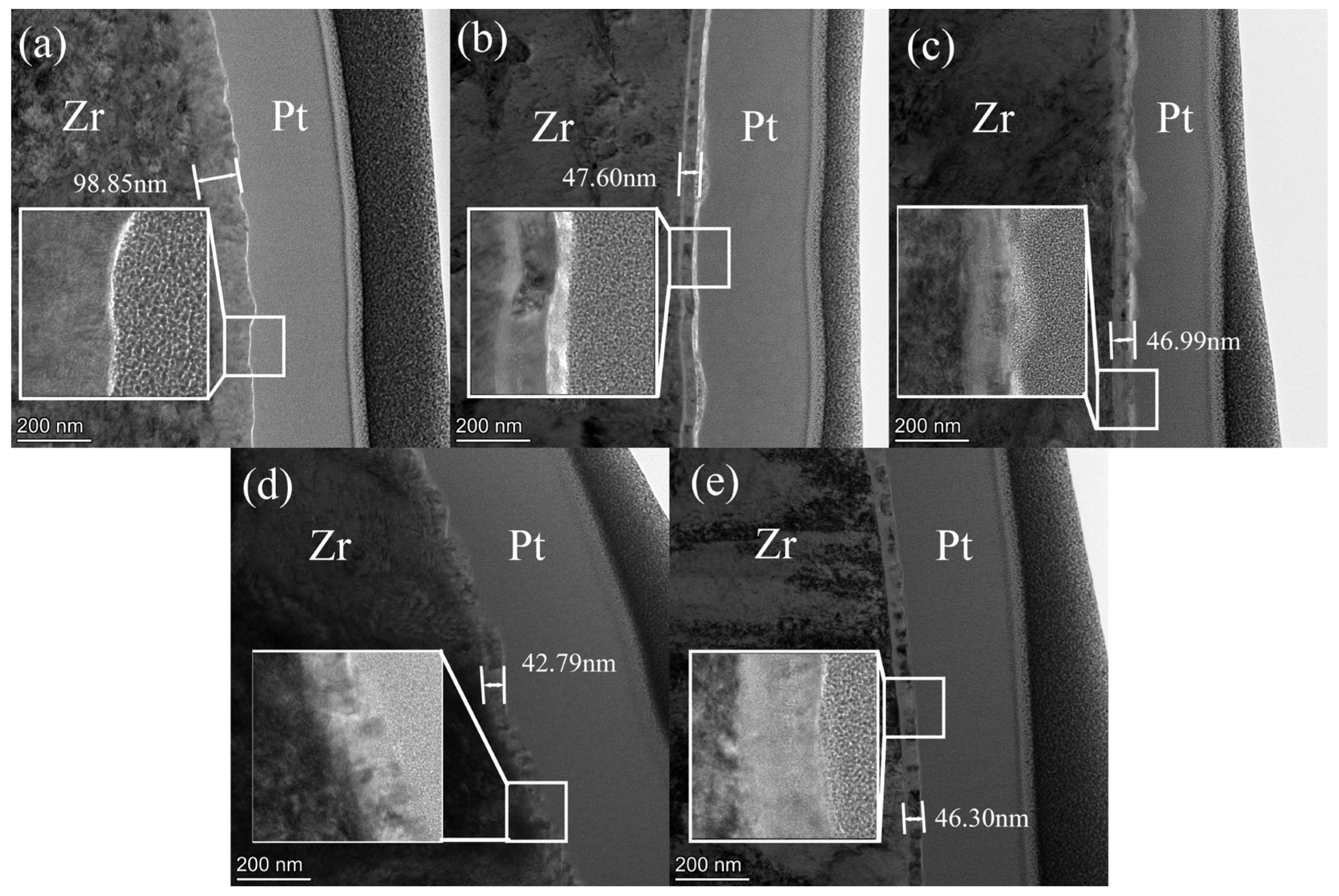
  • The thickness of the oxide films formed on Zr702 immersed in fluorinated nitric acid solution was between 42–48 nm, which is much thinner than that of the oxide layer (~98.85 nm thickness) in the F free HNO3 solution. Therefore, an increase in F ions concentration restricts the oxide film growth and increases the average rate of dissolution of the oxide layer.
  • When the concentration of fluoride ions changes from 0 ppm to 200 ppm, the corrosion rate at the concentration of fluorine ions at 0 ppm and 10 ppm basically remains unchanged within five time periods, while the corrosion rate at 50 ppm to 200 ppm shows a downward trend with the increase of time. The most obvious change is at 48 h when the concentration of fluoride ions increases, the higher the corrosion rate.
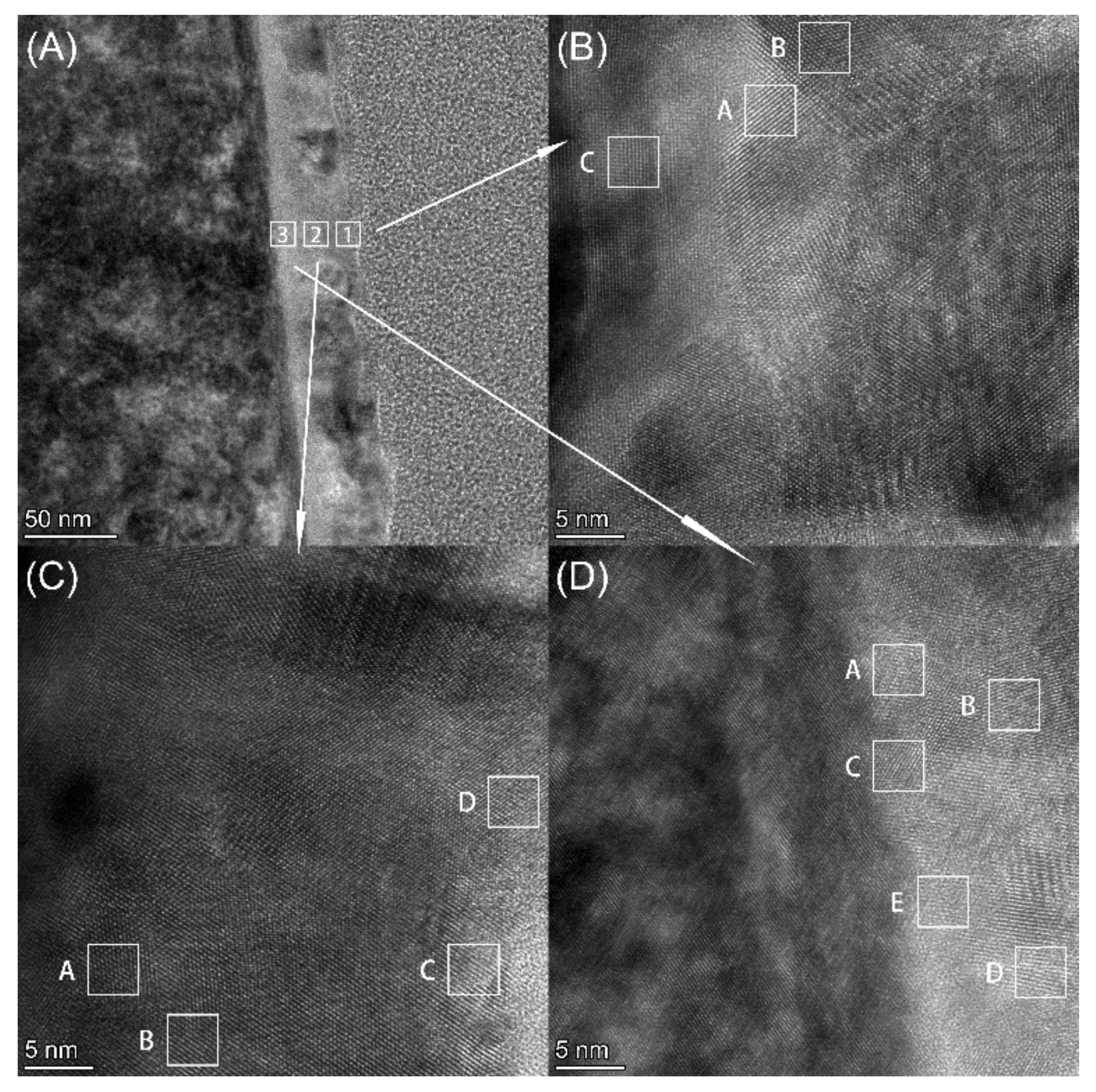
  • The oxide film was identified to be a nanocrystalline cluster in a fluorinated nitric acid solution. The oxide films comprised outermost HfO2 and HfF4 layers, sub-outer ZrO2 and ZrF4 layers, and an innermost Zr (F, O)3.6 layer. From the distribution of the oxide film, it can be seen that in the F-containing boiling nitric acid solution, Hf in the alloy of Zr702 metal will migrate from the inside to the surface to form oxides and fluoride preferentially than Zr, which can play a protective role in Zr702. With the increase of fluorine ion concentration, it will penetrate the oxide film, indicating that fluorine ions have a dissolution effect on the Zr702 oxide film.

Author Contributions

Conceptualization, H.S.; methodology, H.S.; software, Y.L.; validation, H.S., Y.L.; formal analysis, Y.Z.; investigation, J.X.; resources, Y.Z.; data curation, Y.L.; writing—original draft preparation, H.S.; writing—review and editing, Y.L. and W.Z; visualization, J.X.; supervision, W.Z.; project administration, H.S.; funding acquisition, H.S. All authors have read and agreed to the published version of the manuscript.

Funding

This research was funded by the National Key Research and Development Program of China (Grant number: 2021YFB3700802).

Data Availability Statement

Data is contained within the article.

Acknowledgments

The authors acknowledge the support provided by Yi Ding and Wei Xi of the Tianjin Key Laboratory of Advanced Functional Porous Materials and Centre for Electron Microscopy for Transmission electron microscopy analysis.

Conflicts of Interest

Author Hangbiao Su was employed by the company Xi’an QinTi Intelligent Manufacturing Technologies Co., Ltd. Author Jianping Xu was employed by the company Xi’an Rare Metal Materials Institute Co., Ltd. The remaining authors declare that the research was conducted in the absence of any commercial or financial relationships that could be construed as a potential conflict of interest.

References

  1. Arash, F.; Marziyeh, N. Electrochemical Behavior Assessment of Zircaloy-4 in Nitric Acid Solutions by Electrochemical Impedance Spectroscopy and Mott-Schottky Analyses. Anal. Bioanal. Electrochem. 2017, 9, 25–27. [Google Scholar]
  2. Veronika, R.; Jan, M.; Petr, S.; Radek, N.; Aneta, K. Corrosion of zirconium alloys demonstrated by using impedance spectroscopy. J. Nucl. Mater. 2018, 510, 312–321. [Google Scholar] [CrossRef]
  3. Xu, J.; Li, H.; Zhao, X.; Wu, J.; Zhao, B.; Zhao, H.; Wu, J.; Zhang, Y.; Liu, C. Zirconium based neutron absorption material with outstanding corrosion resistance and mechanical properties. J. Nucl. Mater. 2022, 567, 153763. [Google Scholar] [CrossRef]
  4. Mermoux, M.; Duriez, C.; Coindreau, O. High temperature Zircaloy-4 oxidation in water vapour-containing environments examined with Raman imaging and labelled oxygen. Corros. Sci. 2021, 184, 109351. [Google Scholar] [CrossRef]
  5. Fauvet, P. Corrosion issues in nuclear fuel reprocessing plants. In Nuclear Corrosion Science and Engineering; Woodhead Publishing: Sawston, UK, 2012; pp. 679–728. [Google Scholar] [CrossRef]
  6. Heakal, E.; Mogoda, A.; Mazhar, A.; Ghoneim, A. Effect of fluoride media on the stability of anodic ZrO2 films. Corrosion 1990, 46, 247–253. [Google Scholar] [CrossRef]
  7. Jayaraj, J.; Nanda Gopala Krishna, D.; Mallika, C.; Kamachi Mudali, U. Electrochemical Studies and XPS Analysis of the Surface of Zirconium-702 in Concentrated Nitric Acid with and Without Fluoride Ions. Trans. Indian Inst. Met. 2018, 71, 521–531. [Google Scholar] [CrossRef]
  8. El-Mahdy, G.; Mahmoud, S.; El-Dahan, H. Effect of halide ions on the formation and dissolution behaviour of zirconium oxide. Thin Solid Films 1996, 286, 289–294. [Google Scholar] [CrossRef]
  9. Goncalves, Z.; Miinzel, H. Dissolution kinetics of Zircaloy in HNO3/HF mixtures. J. Nucl. Mater. 1990, 170, 261–269. [Google Scholar] [CrossRef]
  10. Jayaraj, J.; Krishnaveni, P.; Krishna, D.; Mallika, C.; Kamachi, U. Corrosion investigations on zircaloy-4 and titanium dissolver materials for MOX fuel dissolution in concentrated nitric acid containing fluoride ions. J. Nucl. Mater. 2016, 473, 157–166. [Google Scholar] [CrossRef]
  11. Hlawka, F.; Sutter, E. Reactivity of the surface of zirconium during pickling in nitric-hydrofluoric acid. Mater. Corros. 1991, 42, 428–436. [Google Scholar] [CrossRef]
  12. Li, Z.; Wu, L.; Ge, R.; Zhang, F.; Shan, Q.; Huang, Y.; Su, R. Erosion corrosion of Ti and Zr in acidic metastannic acid synthesis. Mater. Res. Express 2021, 8, 046528. [Google Scholar] [CrossRef]
  13. Qiu, Z.; Li, Z.; Fu, H.; Zhang, H.; Zhu, Z.; Wang, A.; Li, H.; Zhang, L.; Zhang, H. Corrosion mechanisms of Zr-based bulk metallic glass in NaF and NaCl solutions. J. Mater. Sci. Technol. 2020, 46, 33–43. [Google Scholar] [CrossRef]
  14. Qiu, Z.; Li, Z.; Fu, H.; Zhang, L.; Zhu, Z.; Zhang, H.; Wang, A.; Li, H.; Zhang, H. Effect of pH and NaF addition on corrosion of Zr-based bulk metallic glass in Na2SO4-containing solution. Intermetallics 2021, 129, 107034. [Google Scholar] [CrossRef]
  15. Berry, W.E. Effect of Fluoride Ions on the Aqueous Corrosion of Zirconium Alloys. Symp. Rep. 1964, 149, 28–40. [Google Scholar] [CrossRef]
  16. Gwinner, B.; Badji-Bouyssou, H.; Benoit, M.; Brijou-Mokrani, N.; Fauvet, P.; Gruet, N.; Laghoutaris, P.; Miserque, F.; Robin, R.; Tabarant, M. Corrosion of Zirconium in the Context of the Spent Nuclear Fuel Reprocessing Plant. In Proceedings of the GLOBAL 2015-21st International Conference and Exhibition Nuclear Fuel Cycle for a Low-Carbon Future, Paris, France, 20–24 September 2015. Paper 5265. [Google Scholar]
  17. Gwinner, B.; Balbaud-Celerier, F.; Fauvet, P.; Gruet, N.; Laghoutaris, P.; Miserque, F.; Robin, R. A step towards a better understanding of corrosion of zirconium in nitric acid with additions of fluorine: Focus on the role of the presence of an initial oxide film. Corros. Sci. 2022, 201, 110284. [Google Scholar] [CrossRef]
  18. Jeyaraj, J.; Thinaharan, C.; Ningshen, S.; Mallika, C.; Kamachi, U. Corrosion behavior and surface film characterization of TaNbHfZrTi high entropy alloy in aggressive nitric acid medium. Intermetallics 2017, 89, 123–132. [Google Scholar] [CrossRef]
  19. ASTM Standard G31-72; Standard Practice for Laboratory Immersion Corrosion Testing of Metals. ASTM Standards: West Conshohocken, PA, USA, 2004.
  20. Maiti, H.; Gokhale, K.; Subbarao, E. Kinetics and burst phenomenon in ZrO2 transformation. J. Am. Ceram. Soc. 2010, 55, 317–322. [Google Scholar] [CrossRef]
  21. Ding, Y.; Liu, S.; Xia, C.; Zou, X.; Liu, D.; Wang, Y.; Yang, T.; Li, Q. Thermal oxidation of novel Zr-Ti-Al-V alloy with high strength and toughness and its influence on the corrosion behavior. Surf. Coat. Technol. 2021, 423, 127576. [Google Scholar] [CrossRef]
  22. Uğur, M.; Kadir, C.; Ufuk, M.; Melih, B. Mechanical and electrochemical properties of PEO coatings on zirconium alloy. Surf. Eng. 2020, 36, 800–808. [Google Scholar] [CrossRef]
  23. Stoll, U.; Slavinskaya, N. Corrosion behavior of zirconium alloys in the aqueous environment. Phenomenological aspects. Overview. J. Nucl. Sci. Technol. 2023, 60, 573–602. [Google Scholar] [CrossRef]
  24. Kautz, E.; Gwalani, B.; Yu, Z.; Varga, T.; Geelhood, K.; Devaraj, A.; Senor, D. Investigating zirconium alloy corrosion with advanced experimental techniques: A review. J. Nucl. Mater. 2023, 585, 154586. [Google Scholar] [CrossRef]
  25. Muhammad, M.; Kashif, M.; Waseem, H. Combinatorial development, and assessment of a Zr-based metallic glass for prospective biomedical applications. J. Non-Cryst. Solids 2019, 523, 119544. [Google Scholar] [CrossRef]
  26. Poonam, S.; Anil, D.; Sharma, S. Comparative studies on the corrosion behavior of some Zr based amorphous alloys having different compositions in nitric acid medium. J. Phys. Conf. Ser. 2020, 1455, 012030. [Google Scholar] [CrossRef]
  27. Wagner, A.; Kraut-Vass, A.; Gaarenstroom, S.; Powell, C. NIST X-ray Photoelectron Spectroscopy Database, National Institute of Standards and Technology: Gaithersburg, MD, USA, 2012. [CrossRef]
  28. Chastain, J.; King, R.C., Jr. Handbook of X-ray Photoelectron Spectroscopy: A Reference Book of Standard Spectra for Identification and Interpretation of XPS Data. Phys. Electron. Div. 1992, 40, 221. [Google Scholar]
  29. Morant, C.; Sanz, J.; Galan, L.; Soriano, L.; Rueda, F. An XPS study of the interaction of oxygen with zirconium. Surf. Sci. 1989, 218, 331–345. [Google Scholar] [CrossRef]
  30. Bosman, H.; Pijpers, A.; Jaspers, A. An X-ray Photoelectron Spectroscopy Study of the Acidity of SiO2–ZrO2 Mixed Oxides. J. Catal. 1996, 161, 551–559. [Google Scholar] [CrossRef]
  31. Sleigh, C.; Pijpers, A.; Jaspers, A.; Coussens, B.; Meier, R. On the determination of atomic charge via ESCA including application to organometallics. J. Electron Spectrosc. Relat. Phenom. 1996, 77, 41–57. [Google Scholar] [CrossRef]
Figure 2. XRD pattern of the Zr702 sample impregnated in 6 M HNO3 containing different fluoride ion concentrations.
Metals 14 00479 g002
Figure 3. (A) HAADF-STEM image of a corroded specimen immersed for 240 h in a boiling 6 M HNO3 solution with an F-concentration of 10 ppm, and EDX mapping of (B) O, (C) Zr and (D) Hf. (E) the EDX line scan profiles of O, Zr, and Hf.
Metals 14 00479 g003
Figure 4. TEM characterization of the oxide films formed on the specimens’ surfaces after being subjected to 240 h of corrosion in boiling 6 M HNO3 with F concentrations of (a) 0 ppm, (b) 10 ppm, (c) 50 ppm, (d) 100 ppm and (e) 200 ppm.
Metals 14 00479 g004
Figure 5. High resolution XPS spectra of the Zr702 specimens immersed in 6 M HNO3 (a) Zr 3d; (b) Hf 4f; (c) O1s; and (d) F1s. after they were subjected to corrosion tests.
Metals 14 00479 g005
Figure 6. HRTEM images of three different zones in oxide films of the specimens immersed in HNO3 solutions with 200 ppm F for 240 h (A) outer layer 1# zone, (B) middle layer 2# zone, and (C) inner layer 3# zone (D).
Metals 14 00479 g006
Figure 7. Enlarged view of the high-resolution phases shown in Figure 6. (1-A1-C) are different areas in 1#, (2-A2-D) are different areas in 2#, (3-A3-E) are different areas in 3#.
Metals 14 00479 g007
Figure 8. Corrosion rates (corrosion weight loss) versus exposure time for the Zr702 specimens during each of the five periods.
Metals 14 00479 g008
Table 1. Zr4+ concentration in the HNO3 solutions containing F ions for the five periods.
Zr4+ (μg/mL)F-Concentration in HNO3 (ppm)
Time (h) 01050100200
480.1521.23193366.4691.9
960.2334.14237375.9780.4
1440.2245.34276430.6949.8
1920.4952.16284415.1927.9
2400.3160.19323.6446.91046
Disclaimer/Publisher’s Note: The statements, opinions and data contained in all publications are solely those of the individual author(s) and contributor(s) and not of MDPI and/or the editor(s). MDPI and/or the editor(s) disclaim responsibility for any injury to people or property resulting from any ideas, methods, instructions or products referred to in the content.

