Article

Modified Split Mandrel Method and Equipment to Improve the Fatigue Performance of Structural Components with Fastener Holes

1
Department of Material Science and Mechanics of Materials, Technical University of Gabrovo, 5300 Gabrovo, Bulgaria
2
Department of Industrial Design and Textile Engineering, Technical University of Gabrovo, 5300 Gabrovo, Bulgaria
*
Author to whom correspondence should be addressed.
Metals 2024, 14(3), 303; https://doi.org/10.3390/met14030303
Submission received: 22 December 2023 / Revised: 27 February 2024 / Accepted: 1 March 2024 / Published: 3 March 2024
(This article belongs to the Special Issue Fatigue Behaviour of Aluminum Alloys)

Abstract

:
Fastener holes are among the most common natural stress concentrators in metal structures. The life cycles of various structural elements, such as those in aircraft structures, automobiles, and rail-end bolt joints, are limited by fatigue damage around the holes. An effective approach to delay the formation and growth of fatigue macrocracks is to introduce residual hoop compressive stresses around the holes. Two methods have become established in the prestressing of fastener holes in aircraft components, split sleeve and split mandrel, which implement one-sided processes. The common disadvantage of both methods is the complex procedure due to the need for high accuracy of the initial holes. This article presents a new modified split mandrel method providing the same tightness (interference fit) with a wide tolerance of the pre-drilled hole diameters, reducing the number of technological cycle steps and production costs. To implement the new method, a functionally connected tool and a device with a hydraulic drive were developed. An extensive experimental study of 2024-T3 AA specimens was carried out to evaluate the effectiveness of the method under a high scattering of the pre-drilled holes. The new method provided a deep zone of residual hoop compressive stresses on both faces of the specimens after cold working and after hole final reaming. The removal of a plastically deformed layer around the hole of suitable thickness during the final reaming decreased the axial gradient of residual hoop stress distribution. Fatigue tests on a tensile pulsating cycle verified the effectiveness of the modified split mandrel method to significantly increase the fatigue life by 6.6 times based on 10 6 cycle fatigue strength compared to the conventional case of machining the holes. The obtained S-N curves for three groups of samples with initial hole diameters of 8.0, 8.1, and 8.2 mm, which were cold worked with the same tightness of 0.32 mm and final reamed, aligned well, indicating that the new method can provide constant fatigue strength for a given stress amplitude.

1. Introduction

Fastener holes in metal structures are natural strain and stress concentrators and, therefore, potential sites for the initiation and development of fatigue cracks. Thus, the fatigue life, load-bearing capacity, and safety of metal structures largely depend on the behavior of the material around the fastener holes.
Three approaches exist to increase the fatigue strength of metal components with fastener holes: (1) using super-strength materials (in cases where this is justified), (2) modifying the microstructure of the material around the hole, and (3) introducing useful circumferential residual compressive stresses around the hole. Clearly, these approaches are not independent of each other. For example, hole prestressing via plastic deformation leads to a change in the microstructure of the material around the fastener hole since the modified microstructure is precisely the physical carrier of the residual stresses. The third approach is the subject of the present study. Studies have shown that residual compressive stresses introduced into the surface and subsurface layers of 2024-T3 aluminum alloy hourglass-shaped fatigue specimens subjected to a rotating bending fatigue test increase the time from the nucleation of microcracks to fatigue macrocrack formation and subsequent macrocrack development to the formation of an open crack [1]. Similar is the failure mechanism of a flat specimen with a prestressed hole subjected to cyclic tension, where the circumferential residual compressive stresses around the hole are of primary importance for fatigue life.
The basic mechanical approach for introducing residual compressive stresses around a fastener hole is cold working, which is carried out at a lower temperature than that of recrystallization. The methods implementing cold working and aiming to introduce compressive residual stresses around the hole can be classified into two groups: (1) tool impact on the flat surfaces, such as ring groove coining [2], pad coining [3], “improving fatigue life of holes” [4], and using stress waves [5], and (2) tool impact on the hole surface. The second group comprises methods that either (a) introduce a relatively narrow zone of compressive circumferential stresses around the hole or (b) implement a relatively wide pressure zone around the opening.
Methods that use the narrow pressure zone are applicable to holes of lesser importance. For example, Christ et al. [6] invented a combined tool for consecutively drilling, reaming, and burnishing holes in aircraft components. A new concept for increasing the fatigue life of several fastener holes in aircraft structures was proposed by Duncheva et al. [7], who developed a method for the prestressing of fastener holes called friction stir hole expansion. Similarly, Maximov et al. devised a technique and tool for processing several small fastener holes in high-strength Al alloy structures [8]. The deforming portion of the tool is specifically profiled in its cross-section so that the full contact with the hole surface is disrupted. Thus, their method produces three beneficial effects: hole cold expansion, burnishing, and surface microstructure modification (friction stir and torsion due to tool rotation). Finally, Kumar et al. [9] proposed a novel technique for cold expansion using a rotating tapered mandrel, which combines cold expansion and friction processing.
The second subgroup of methods (i.e., creating a wide pressure zone) introduces compressive residual stresses in significant depth. The following methods correspond to this subgroup: ball or solid mandrel cold working [10], prestressing of fastener holes by tapered pin and tapered sleeve [11], split sleeve cold expansion [12], cold working using a seamless tubular member [13], split mandrel cold working [14], and cold working using a rotational mandrel and tubular seamless sleeve made of shape memory alloy [15]. Several new methods belonging to this subgroup have recently been proposed. For instance, Maximov and Duncheva [16] invented a method and tool ensuring “pure” radial cold hole expansion, introducing nearly uniform residual hoop stresses around the hole along its axis that has a minimized and symmetric gradient with respect to the plate middle plane. Because of this advantage, the authors dubbed their method “symmetric cold expansion”. Another advantage is its one-sided process, like the split sleeve and split mandrel.
In addition to static methods, dynamic methods are also used in the aerospace industry to increase the fatigue life of structural elements with fastener holes, such as the classic shot peening [17,18]. In the last few years, various dynamic hole cold-working methods have been presented, which have a common technical basis: an electromagnetic load. They implement two concepts: mechanical cold-working methods based on electromagnetic driving [19,20] and a non-contact electromagnetic cold hole expansion process based on radial pulsed electromagnetic force [21,22]. For example, Guo et al. [19] proposed a novel dynamic cold expansion method using a mandrel driven by a driving head through the electromagnetic dynamic force. Their method reduces expansion resistance, generates more uniform hole diameter distribution along the hole axial direction after cold expansion, and exhibits higher fatigue life compared to static mandrel cold working. Additionally, Guo et al. [20] proposed a novel stress wave strengthening method based on electromagnetic force to improve the fatigue life of plate-holed structures. Their double-side stress wave strengthening method extended the fatigue life of 6061-T6 aluminum alloy holed-plate samples compared to cold expansion, while their single-side stress wave strengthening exhibited lower fatigue life than cold expansion.
In another study, a dual-stage non-contact electromagnetic cold hole expansion process [21] was designed and implemented using two outer and two inner coils that are symmetrically arranged adjacent to the top and bottom faces of the workpiece. In 2A12-T4 aluminum alloy, their proposed process was more efficient compared with the conventional mechanical cold expansion process because of the non-contact characteristic and uniform residual stress distribution. In relevant research, Geng et al. [22] proposed a simplified single-coil non-contact electromagnetic cold hole expansion process. Their fatigue test results showed significant improvements in the fatigue performance of the 2A12-T4 specimen, and good surface integrity and grain refinement were observed near the hole. The electromagnetic-load-based methods require sophisticated specialized equipment and are effective on relatively thin sheet blanks. In addition, the non-contact methods require a relatively accurate centering of the treated hole.
Recently, the literature has focused on cold expansion methods, which also provide an additional effect of improving hole surface integrity. For instance, Cao et al. [23] developed a new technique for prestressing holes in nickel-based superalloy involving a laser texturing process followed by the Hertz contact rotary expansion process, where the cylindrical sleeve is the critical component connecting the two processes. The latter process acts on the hole via the rotary’s extruding movements on the strengthened sleeve and conical mandrel tools. The proposed technique significantly improves the hole surface integrity because of grain refinement near the hole wall and introduces deeper compressive residual stress distribution.
In other research, a significant effect of improving the Inconel 718 superalloy was achieved using a novel cold expansion process with a small, deep hole (with diameter < 2 mm and depth > 10 mm), called the multi-spherical bump rotating cold expansion process [24]. The tool (tungsten cemented carbide mandrel) used in this process plays a key role but requires complex technology, including fine grinding, laser texturing, and PVD coating. The authors report that average fatigue life at 400 °C significantly increases compared to the small, deep hole after reaming.
In general, these techniques require specific tools with relatively complex technology to produce. The tendency to emphasize the microstructure in the vicinity of the stressed holes is also observed in relation to studies of the direct cold expansion process. For example, Wang et al. [25] investigated the effect of cold expansion on the high-temperature low-cycle fatigue performance of the nickel-based superalloy hole structure. According to the authors, the surface smoothing, surface compressive residual stress field, and cold-work–hardened structure with the sub-grain refinement were responsible for increasing the fatigue life.
Despite the many existing methods for cold hole working and their advantages, two methods have become established in the practice of prestressing fastener holes in aircraft components: split sleeve cold expansion and split mandrel cold working. Collectively, these methods have been referred to as mandrel cold-working methods. The essence of these methods is the generation of a field of residual compressive stresses around the hole due to plastic deformation by applying a tool with a diameter larger than that of the pre-drilled hole. Although this type of prestressing of fastener holes has been highly useful over recent years, the main disadvantage inherent in the mandrel cold-working methods is the significant and nonsymmetrical gradient of the residual hoop stresses relative to the middle plane of the plate due to axial force flow passing through the mandrel–plate–support system. Other disadvantages include considerable surface upset, especially on the exit face and around the hole edge, and the appearance of a bending moment, which causes local buckling of the material.
Still, the main role of the split (both of the sleeve and the mandrel) is to implement a one-sided process. However, this benefit of both methods brings with it additional drawbacks: the requirement for precision in the starting hole size to achieve uniform expansion; treatment requiring the use of two reamers, one for the starting hole diameter and one for the final hole diameter; the need for intermediate dimensional control operations; and non-axisymmetric expansion in the hoop direction. Additional disadvantages of the split sleeve method include the pre-lubricated split sleeve for one-time use, the requirement for lubricants, and the residual effect of lubricants. Nevertheless, apart from the residual stresses and fatigue performance, studies of the microstructure around the holes after the split sleeve cold expansion process for AZ31B magnesium alloy sheet [26] and 7075-T6 aluminum alloy [27] are of interest. Furthermore, Lv et al. [28] used finite element analysis to investigate the distribution and variation of residual stresses along the hole edges of 7075 aluminum alloy single-hole and multi-hole split sleeve cold expansion specimens.
Comparative extensive analyses between the split sleeve and split mandrel methods have shown the advantages of the split mandrel over the split sleeve method [29,30]. The main advantage of split sleeve and split mandrel methods (as well as symmetric hole expansion [16]) is that they realize a one-sided process, i.e., these methods require access from only one side of the plate (only one operator): they are relatively fast and allow automatization of the assembly operations.
The split mandrel process utilizes a collapsible mandrel 1 with a sliding pilot cylindrical shaft 4 extending through the mandrel cylindrical hole, which serves to solidify the mandrel prior to cold working the plate hole 2 (Figure 1). With the pilot retracted, the mandrel is partially collapsible, allowing insertion into the pre-drilled hole. When the puller unit is actuated, the pilot extends through the mandrel’s cylindrical hole, which solidifies. The solidified mandrel is then pulled through the hole, plastically deforming the surrounding material and creating a residual compressive field [30].
The typical split mandrel process is implemented in 11 steps [31]:
(1)
Drill the start hole with a start drill.
(2)
Ream the hole to the proper starting size with the start hole reamer.
(3)
Verify the start hole with a hole gage.
(4)
Inspect the mandrel by inserting an inspection pin at the end of the mandrel and check the mandrel with a wear gage.
(5)
Start the pass-through of the hole, after which the hollow, split mandrel collapses.
(6)
Once pass-through is complete, place nose cap flush to the material. The pilot extends and solidifies the hollow mandrel.
(7)
Start cold working, drawing the solidified mandrel back through the material.
(8)
Complete cold working, allowing the mandrel to return to its ready position.
(9)
Inspect the cold-worked hole with a hole gage.
(10)
Ream the hole to its final size with a piloted reamer.
(11)
Inspect the final reamed hole with a hole gage. Countersink if necessary.
The degree of cold expansion (DCE) of the hole is calculated by the following formula:
D C E = D d d × 100 ,   %
where D is the mandrel major diameter and d is the start nominal hole diameter. The DCE depends on the diameter d tolerance and the diameter D scattering. The scattering is a function of the wear of the cylindrical working surface of the pilot, the hole in the hollow mandrel, and the cylindrical strip of the mandrel diameter D. To secure the designated DCE, steps two, three, and four are included in the technological process.
This paper proposes a new method and device for cold expansion of holes [32] which is based on the split mandrel cold-working method. The main goal is to reduce the number of steps through which the technological process is implemented, reducing production costs. Unlike the baseline method, the new method does not require a tight tolerance on the diameter of the pre-machined holes. Instead, this modified method involves a split hollow mandrel with a central hole with a conical surface (which is suitably profiled so that the radius of curvature is the same). An axially movable pin having an outer conical surface (which is profiled in the same way as the conical surface of the hole in the hollow mandrel) is positioned in this hole. The two conical surfaces (of the hole and the pin) have the same slope angle α and expand in the direction of the mandrel split end. After introducing the split hollow mandrel into the drilled hole, the pin is moved axially until the two conical surfaces contact and solidify the mandrel, whereby the cylindrical surface of the solidified mandrel contacts that of the pre-drilled hole. Thus, a constant tightness (interference fit) is achieved regardless of the tolerance of the pre-drilled hole, and conditions are created to eliminate the second, third, fourth, and ninth steps of the technological process.
This study aimed to evaluate the effectiveness of the modified split mandrel method experimentally for the enhancement of the fatigue life of holed structural components in aircraft components, specifically regarding the result repeatability. To achieve the goal, the following tasks were conducted: (1) an experimental study of the influence of the pre-drilled hole tolerance on the diameters of the stressed and final reamed holes; (2) X-ray diffraction analysis of residual stresses around fastener holes introduced by the modified split mandrel process; and (3) an experimental investigation of the fatigue behavior of specimens with fastener holes subjected to cold expansion by the modified split mandrel process.

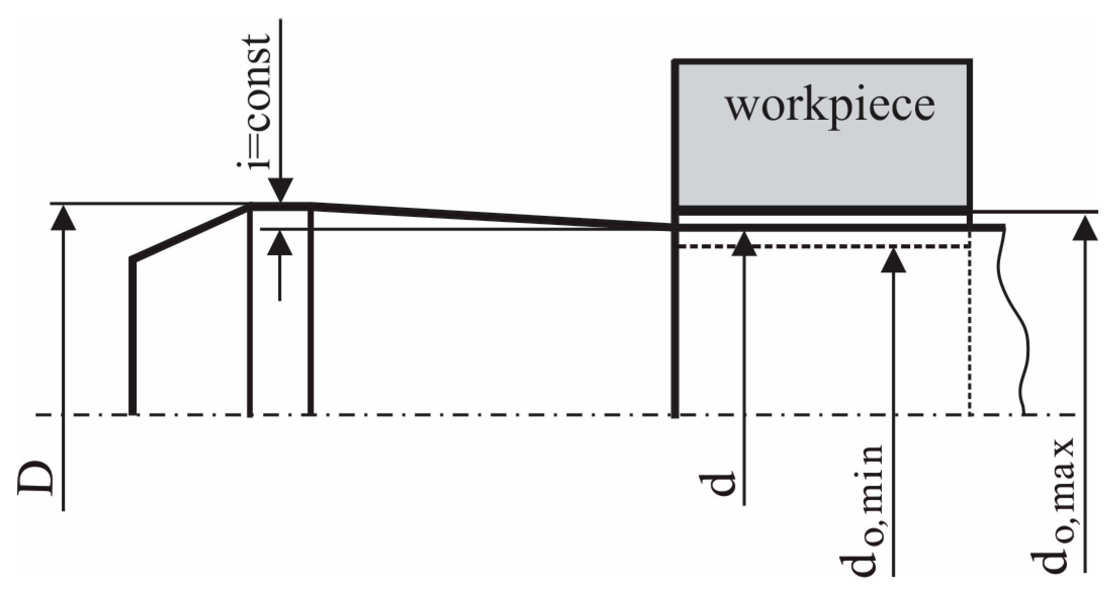
2. Nature of the Proposed Method

A characteristic feature of the basic split mandrel cold-working method (as well as the split sleeve cold expansion method) is the requirement for a very narrow tolerance of the pre-drilled hole diameter, which generally makes the technological process of manufacturing the components more expensive. At the same time, the tightness is a variable within this tolerance, as it is defined by the difference between the major diameter of the split mandrel and the pre-drilled hole diameters. The basis of the proposed modified method is the elimination of the mentioned shortcomings. For the technical implementation of the new method, a tool and a device for cold expansion were developed, achieving constant tightness with a relatively wider diametrical tolerance of the pre-drilled holes [32].
Figure 2 shows the tool geometry and the main stages for the cold working of holes using the new tool and device. The tool includes a partially longitudinally split mandrel so that at least three symmetrical segments are formed. An axially movable conical–cylindrical pin is positioned in the axial hole of the mandrel. The mandrel working part comprises two conical surfaces connected by a cylindrical surface. The pin’s conical surface contacts the surface of a conical hole made in the split end of the mandrel. The two conical surfaces have the same angle of inclination α. The mandrel’s conical working surface transitions into a cylindrical surface on which the hole to be cold worked is based. The procedure for the proposed method contains the following stages:
Stage I. Inserting the mandrel into the pre-drilled hole.
The tool insertion is facilitated by the front conical surface on the working part of the split mandrel (Figure 2a). Clearance exists between the cylindrical base surface of the mandrel and the surface of the hole, except for those holes that are drilled at the lower limit of their diametrical tolerance range. The conical–cylindrical pin is moved axially with respect to the mandrel to the left such that its conical surface does not contact the conical surface of the hole in the mandrel (Figure 1a). This allows elastic deformation of the split mandrel segments in a radially inward direction, facilitating the introduction of the mandrel into the pre-drilled hole in the workpiece.
Stage II. Compensation for the clearance between the cylindrical surface of the mandrel and the drilled hole.
To compensate for the clearance, the conical–cylindrical pin is moved axially until its conical surface contacts the conical surface of the hole in the mandrel, causing the mandrel segments to move radially outward, resulting in a hard contact between the mandrel and the hole surface (Figure 2b). In this position, the major diameter D (Figure 3) of the mandrel’s working cylindrical surface is larger than the diameter d 0 of the pre-drilled hole in the workpiece. The presence of hard contact achieves constant tightness during the cold-working process since the tightness depends only on the difference between the mandrel’s major diameter D and the diameter d of its cylindrical surface (Figure 3).
Stage III. Cold working.
Cold working is realized by the axial movement of the mandrel together with the conical–cylindrical pin, such that the working conical and cylindrical surfaces of the mandrel are moved along the pre-drilled hole’s axis, deforming the hole plastically (Figure 2c).
Stage IV. Creating an area of useful hoop residual stresses around the hole.
After the tool exits the hole, the plastically deformed layer of metal around the hole (whose diameter has increased) opposes the natural tendency of the material particles to occupy their original position. The inhibited shrinkage of the metal around the hole results in the formation of a zone of useful circumferential residual compressive stresses (Figure 2d), which is characteristic of mandrel cold-working methods [12,14,16,31].
Figure 3 illustrates the geometry of the mandrel working part. After ensuring hard contact (i.e., completing Stage II), the tightness i during the cold working is a constant that depends only on the two mandrel diameters (D and d), and not on the scattering of the drilled hole diameters:
i = D d = c o n s t
The change in tightness over time is determined solely by the wear of the working parts of the split mandrel. The DCE is equal to the hoop linear strain ε τ for the points on the hole surface. The DCE limits are defined by the minimum and maximum allowable diameters of drilled holes, d 0 , min and d 0 , max , respectively (Figure 3):
D C E max = ε τ , max = i d 0 , min × 100 ,   % ,   D C E min = ε τ , min = i d 0 , max × 100 ,   %
For example, if the tightness is i = D d = 6.34 6.04 = 0.3   m m and the limit diameters of drilled holes are d 0 , min = 6   m m and d 0 , max = 6.06   m m , the DCE limit values are D C E min = i d 0 , max × 100 % = 4.95 % and D C E max = i d 0 , min × 100 % = 5 % . Thus, the DCE deviation is 0.05%, while the deviations of the diameters of the drilled holes with respect to d are + 0.33 % and 0.66 % . In other words, the variation of the DCE is insignificant compared to the relative variation interval of d 0 . Therefore, the scattering of drilled hole diameters changes the DCE very little.
For an unhindered insertion of the split mandrel into the pre-drilled holes, the following geometric condition must be met:
D 2 δ 2 δ t g 180 ° n s d 0 , min
where n s is the number of segments in the longitudinally cut mandrel and δ is the width of the cuts in the mandrel (see Figure 2).

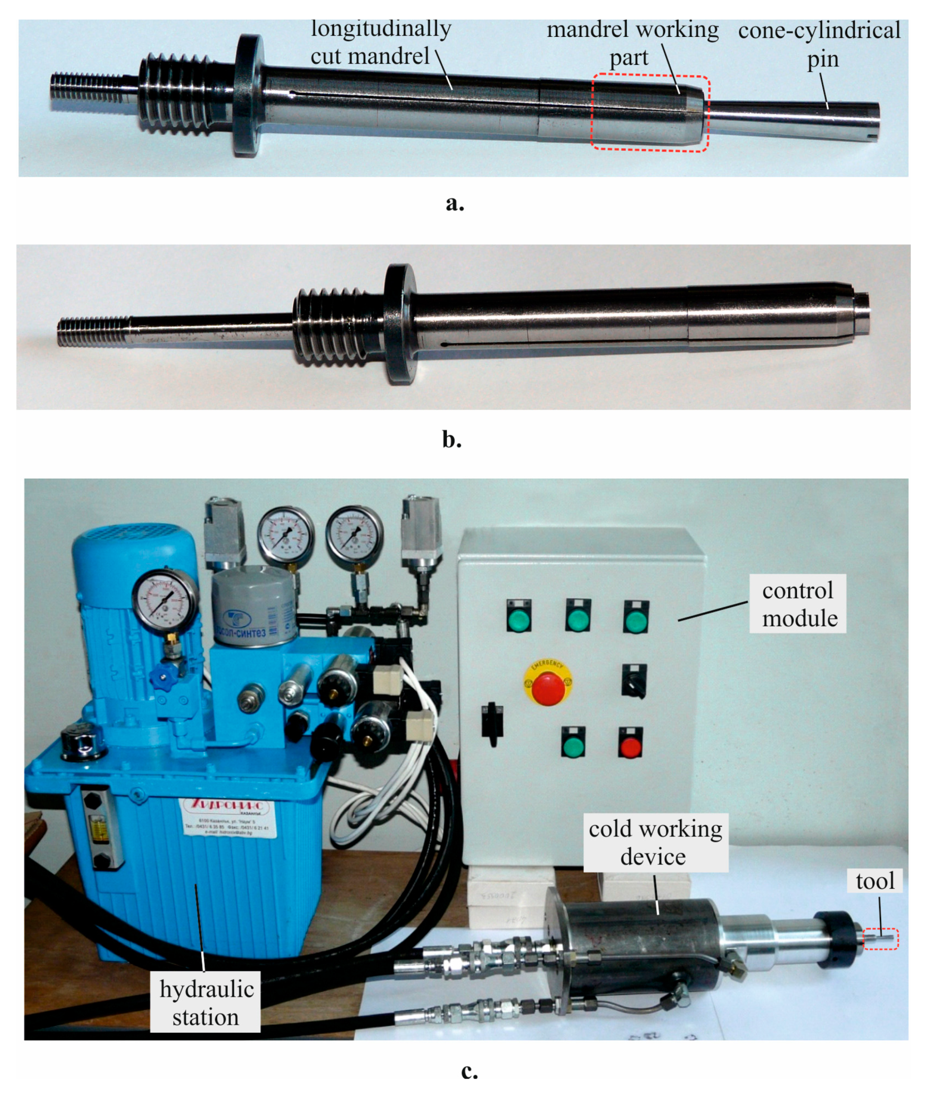
3. Materials and Methods

3.1. Materials

The material under test was aluminum alloy 2024-T3, obtained as (1) hot-rolled bars with a diameter of 32 mm, used to study the influence of the tolerance of the pre-drilled holes in a geometrical aspect and the evolution of the residual circumferential stresses (X-ray diffraction analysis); (2) 5 mm thick sheets, used to make one-dimensional tensile and fatigue test specimens. An Optical Emission Spectrometer was used to determine the chemical composition. The apparatus measured the content in weight percentages, as the minimum value of the step for determining the content of a chemical element is 0.001. The chemical compositions of the two materials are shown in Table 1. The two chemical compositions have similar values for their respective chemical elements.
The mechanical characteristics of the aluminum alloy were established via a one-dimensional tensile test on the flat specimens using a Zwick/Roell Vibrophore 100 testing machine. The specimen dimensions are in accordance with ASTM E 466-07 and shown in Figure 4. The sample thickness was 5 mm. To evaluate the effect of the presence of a central hole, the mechanical tensile tests were carried out for two cases—without and with a central hole with a nominal diameter of 8.5 mm. The result for each group was established as the arithmetic mean obtained from three specimens showing that the presence of a central hole has little influence on the static mechanical characteristics of the studied alloy (Table 2).

3.2. New Method Implementation

To implement the modified split mandrel method, a tool and device with a hydraulic and electronic drive and control were designed and manufactured (Figure 5). The longitudinally split mandrel and the conical–cylindrical pin were fixed to the device via threads. Four symmetrical segments were formed in the partially longitudinally split mandrel, and the width of the sections in the mandrel was δ = 0.5   m m . The diameters of the working part of the split mandrel were D = 8.37   m m and d = 8.05   m m . Thus, the mandrel working part provided a constant tightness i = 0.32   m m .

3.3. Experimental Study of the Influence of Pre-Drilled Hole Tolerance on Cold-Expanded Hole Diameter Using the New Method

To assess the effectiveness of the new method, stressing pre-drilled holes with at least twice the diameter tolerance compared to that of the known split sleeve and split mandrel methods was tested. Thus, the pre-machining of the holes involved only drilling, eliminating subsequent reaming. Evaluating the effectiveness of the new method in production conditions required an experimental evaluation of its technological capabilities in terms of the influence of the pre-drilled hole tolerance on the stressed and final reamed hole diameters.
An experimental study was carried out on 34 bushing samples with the following nominal dimensions: outer diameter of 32 mm and height of 8 mm. The front surfaces of the samples were ground. Using this shape of the specimens excluded the influence of the external boundaries on the strained and stressed states around the holes. The research was conducted in the following sequence:
(1) Drilling the holes. Since the aim was for a relatively greater scattering of the drilled hole diameters, a column drill was used, along with a 7.98 mm diameter drill bit.
(2) Measurement of hole diameters d 0 and out-of-roundness Δ d 0 in three sections: entrance face (side “a”), exit face (side “b”) relative to the feed movement of the drill, and the middle plane. Dimensions were measured with an accuracy of up to 1   μ m using an Alberlink Axiom tss three-coordinate measuring machine.
(3) Identification of the three specimens having the minimum diameter d 0 , min , maximum diameter d 0 , max , and average diameter of the hole after drilling, respectively. The samples were labeled as follows: S p min , S p max , and S p a v , respectively.
(4) Cold working of the specimen holes. The specimens were oriented to the front surface of the support flange of the device in the same way; the entrance face was in contact with the support. This orientation of the specimens corresponded to the case when all operations (i.e., drilling, mandrel cold working, and reaming) are performed under conditions of one-sided access. In this specific case, side “a” coincided with the exit face in terms of the direction of the cold-working tool’s pulling motion.
(5) Measurement of diameters of stressed holes in characteristic sections. As a consequence of the split mandrel, in the surface areas of the holes located opposite the slots in the mandrel, the material did not undergo such plastic deformation as in the areas in contact with the segments. As a result, the diametrical dimensions of the stressed holes were measured in two ways: (a) with a measuring pin passing through the hole, and (b) using the Alberlink Axiom tss three-coordinate measuring machine. The first measurement determined the minimum value of the diameters d c w , i in the axial sections of the samples corresponding to the middle of the notches in the mandrel. The second measurement determined the diameters in the three cross-sections: exit face (corresponding to side “a” when drilling), middle plane, and entrance face (corresponding to side “b”). These diameters corresponded to the axial sections in the samples faced in the circumferential direction at 45 ° to those in the first measurement. During the second measurement, in the areas in contact with the split mandrel segments, deviations from roundness Δ d c w were also measured.
(6) Comparing the diametric dimensions measured after drilling with those after cold working of samples with the maximum and minimum hole diameters. Small differences confirmed similar scattering of the holes after drilling and after cold working. Thus, the capability of the new method to compensate for the relatively broad tolerance of pre-drilled hole diameters could be evaluated.
(7) Selection of a reamer for the final reaming of holes and statistical evaluation of the scattering of the final dimensions of processed holes. The reamer diameter d f r was selected according to the condition: d f r d C W max , where d C W max is the maximum measured diameter after cold working.

3.4. Residual Stress Measurement

The experimental specimens were bushing type with the following nominal overall dimensions: outer diameter D = 32 mm and thickness δ = 6   m m . To evaluate the influence of the scattering of the pre-drilled hole diameter, the tests were carried out on four samples whose holes were successively drilled and reamed to obtain the following nominal diameters d 0 : 8.14, 8.16, 8.20, and 8.30 mm (Figure 6). After cold working, the holes were further machined by sequential reaming to obtain the following diameters: 8.4, 8.5, and 8.6 mm. Thus, the influence of the thickness of the metal’s cut layer around the stressed holes on the redistribution (evolution) of residual hoop stresses could be evaluated in correlation with the diameters d 0 .
A D8 ADVANCE diffractometer with a pin-hole collimator with a 1 mm diameter was used to measure the residual stresses. The mode of operation of the X-ray tube (high voltage/current) was 30 kV/40 mA. The sin 2 ψ method and a numerical procedure based on the method of least squares were used. The measured diffraction profile of the Al {311} plane had a maximum at 2 θ 139.3 ° for the used chromium radiation filtered by a VKα filter. The diffraction profiles were determined via the Pearson VII method, calculating the deformations of the aluminum alloy lattice in the Al {311} direction. The Winholtz–Cohen method was applied for the generalized Hooke’s law with the following elastic constants: s 1 = 4.514   T P a 1 and 1 2 s 2 = 18.19   T P a 1 . The following parameters were used in the experiment: 2θ range of 135 ° 143 ° , 2θ step of 0.5 ° , and a slope defined via sin 2 ψ = 0, 0.1, 0.2, 0.3, 0.4, 0.5 for both positive and negative values of the angle ψ . The effective penetration depth of CrKα radiation was in the range 6.5 11   μ m .
Taking into account the physical essence of the modified split mandrel method, the goal of the measurement was to determine the hoop residual stresses in the radial direction from the hole edge on the entrance and exit faces (in terms of tool movement) in the following two characteristic planes: (1) the plane of symmetry of the segment and (2) the plane of symmetry of the notch.
To evaluate the influence of the pre-machined hole tolerance and the thickness of the cut layer of metal during the final reaming on the evolution of the circumferential residual stresses, the study included the following three stages:
(1)
Investigation of the influence of the scattering of the pre-processed hole diameters (and, thus, DCE) on the residual stress distribution after cold working.
(2)
Study of the evolution of residual stresses depending on the thickness of the cut metal layer during final reaming.
(3)
Investigation of the influence of the pre-processed hole diameter scattering (and, thus, DCE) on the final residual stress distribution when ensuring the same final diameter.

3.5. Fatigue Tests

Four groups of fatigue specimens, differing only in the way the holes were treated, were fabricated with dimensions according to Figure 4 but with a central hole:
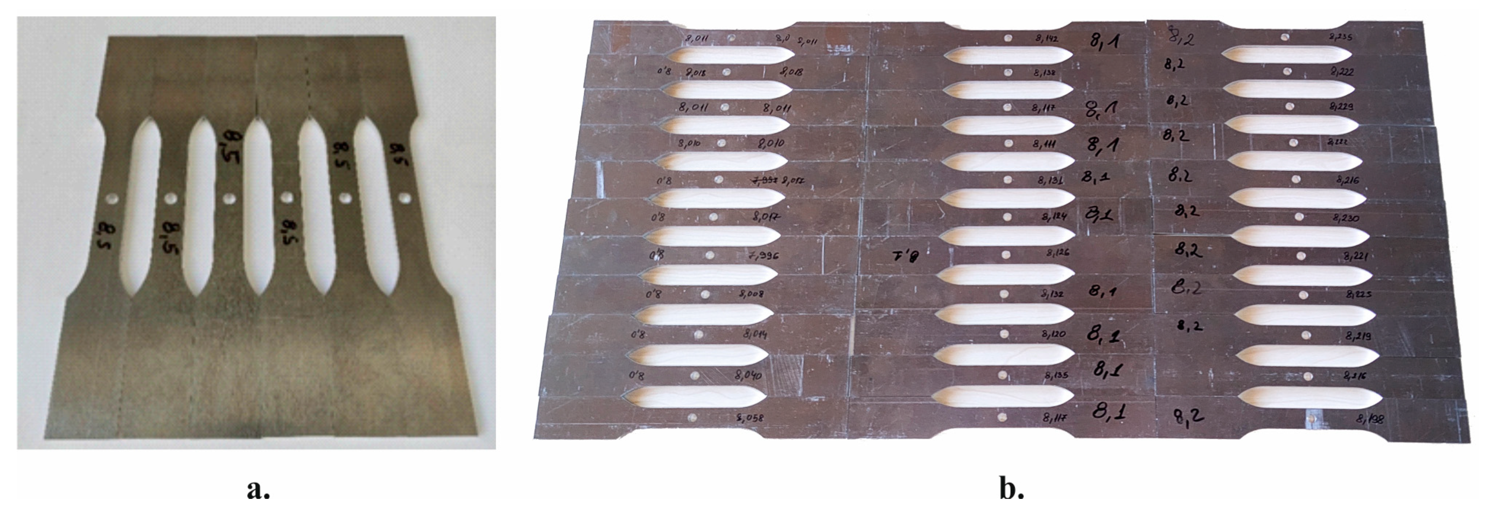
  • Group I (reference). The holes had a diameter d 0 = 8.5   m m machined by cutting on a milling machining center using interpolation (Figure 7a).
  • Group II. The holes were machined in the following sequence: cutting on a milling machining center to a diameter d 0 = 8.0   m m , cold working with D C E = i d 0 × 100 = 0.04 × 100 = 4 % , and final reaming to a diameter of 8.5 mm (Figure 7b).
  • Group III. The holes were machined in the following sequence: cutting on a milling machining center to a diameter d 0 = 8.1   m m , cold working with D C E = i d 0 × 100 = 0.0395 × 100 = 3.95 % , and final reaming to diameter of 8.5 mm (Figure 7b).
  • Group IV. The holes were processed in the following sequence: cutting on a milling machining center to a diameter d 0 = 8.2   m m , cold working with D C E = i d 0 × 100 = 0.039 × 100 = 3.9 % , and final reaming to diameter of 8.5 mm (Figure 7b).
The modified split mandrel process was carried out with the same orientation in the hoop direction of the split mandrel: the tool was positioned so that the plane of the critical section of the specimen coincided with the plane of symmetry of any segment. This sequence of hole processing ensures the same final hole diameter and, thus, the same critical section of the fatigue specimens of all groups. On this basis, the following comparative assessments could be conducted: (1) evaluating the effect of the modified split mandrel method based on a comparison of Groups II, III, and IV with Group I, i.e., with the conventional case of machining the holes by cutting only (drilling and reaming); (2) evaluating the effect of scattering of the pre-drilled hole diameters (before cold working) on the fatigue behavior of the respective samples; and (3) evaluating the repeatability of the fatigue behavior.
The fatigue behavior of the specimens from each group was investigated via pulsating cycle fatigue tests ( R = 0 ) since it is the most severe of all tensile fatigue tests. A Zwick/Roell Vibrophore 100 testing machine in the dynamic mode of operation (Zwic/Roell, Ulm, Germany) was used (Figure 8). The stress amplitude is the ratio of the maximum tensile load to the net cross-sectional area (through the central hole). Fatigue tests were performed at a frequency corresponding to a selected resonance frequency by the testing machine. Since all the samples had the same nominal dimensions (including the hole diameters achieved by the final reaming) and were fixed in the same way in the testing machine working bodies, their natural frequencies were the same (the inevitable deviations had no practical meaning). Thus, the selected frequencies for all samples were in the interval 52.2–52.5 Hz. In this study, the fatigue behavior was evaluated based on tests up to N = 10 6 cycles. The experimental results for all groups were summarized in S-N curves in a double logarithmic coordinate system.

4. Results and Discussion

4.1. Influence of Pre-Drilled Holes’ Tolerance on Cold-Expanded Holes in a Geometrical Aspect

The clearance compensation between the base cylindrical surface of the split mandrel and the surface of each pre-drilled hole was determined by the minimum value of the measured d 0 for the three sections: entrance face (side “a”), middle plane, and exit face (side “b”). Based on the measured minimum hole diameter values after drilling, a distribution histogram for d 0 was built (Figure 9). The histogram was plotted for interval length
d 0 , max d 0 , min s = 0.005   m m ,
where s is the number of intervals (i.e., 9); f i = z i n w is the relative frequency, where n w is the total number of samples (i.e., 34) and z i is the number of samples whose diameters fall within a given interval. The scattering of hole diameters after drilling was
d 0 , max d 0 , min = 8.045 8 = 0.045   m m .
The DCE limits were as follows:
D C E min = i d 0 , max × 100 = 0.0397 × 100 = 3.97 % ,
D C E max = i d 0 , min × 100 = 0.04 × 100 = 4 % .
The geometric condition for unhindered entry of the split mandrel (see Equation (4)) was fulfilled:
8.37 2 0.5 2 0.5 t g 180 ° 4 = 7.855   m m < d 0 , min = 8.00   m m .
The measured hole diameters d 0 after drilling and the deviations from roundness Δ d 0 for the three sections of the identified samples S p min (with minimum diameter), S p a v (with average diameter), and S p max (with maximum diameter) are shown in Table 3. The measured geometric parameters of the holes in samples S p min , S p a v , S p max , and after cold working are shown in Table 4. The minimum diameters d C W , i , min were measured in the axial sections corresponding to the plane of symmetry of the slots in the mandrel, and the diameters d C W and out-of-roundness Δ d C W were measured in the axial sections corresponding to the planes of symmetry of the segments.
The difference between the diameters d C W , i , determined on the basis of the specimens with maximum and minimum diameter after the cold working ( S p max and S p min specimens), was
d C W , i , max d C W , i , min = 8.16 8.12 = 0.04   m m .
In addition, the differences between the measured diameters d C W , i for samples S p max and S p min for the entrance face, middle plane, and exit face were 0.045, 0.044, and 0.039 mm, respectively. These values were similar to the diameter differences measured in these samples after drilling. This result indicates the technological possibilities of the modified split mandrel cold-working method for compensating the clearance between the base cylindrical surface of the mandrel and the surfaces of the pre-drilled holes with a relatively wider tolerance.
Based on the maximum measured value of d C W = 8.287   m m from Table 4, a reamer with a diameter of d f r = 8.3   m m was selected for the final reaming of the holes, which was performed on a Haas Mini Mill machining center. After reaming, the final hole diameters d f and the deviations from roundness Δ d f in the three sections were measured. A histogram visualizing the scattering of final hole diameters d f in the three sections is shown in Figure 10.
Figure 10 indicates that the greatest scattering of the final reamed hole diameters d f was observed on the front side of the samples, corresponding to the side of the entry of the working part of the tool (cold working entrance face), and the least occurred on the side of the exit face (cold working exit face). Additionally, the average final diameter was maximum in the section from the entrance face, and the smallest was in the section from the exit face (Table 5), i.e., cone-shaped holes were observed after final reaming. This phenomenon was due to the non-uniform stressed and strained state in the different cross-sections along the sample thicknesses as a result of the deformation wave moving along the axis of the hole during the pulling movement of the tool. At the hole surface located near the cold working entrance face, the stressed state was two-dimensional, while the strained state was three-dimensional. The mid-section points of the specimens were in a near-plane-strained state due to the influence of the adjacent layers. Near the cold working exit face, the area in contact with the support flange of the cold-working device, the stressed state was three-dimensional. On the other hand, the translational deformation wave along the hole axis caused the holes to have a conical shape and a surface upset effect [33]. In summary, an axial gradient was presented in the stressed and strained state inherent in mandrel cold-working methods [26,27].
For functional purposes, for holes stressed using the new method, the differences in the dispersion of the final hole diameters d f in the three cross-sections are of no practical significance. The arithmetic mean values d ¯ f (Table 5) represent the centers of distribution of the final hole diameters in the three sections. On this basis, the center of distribution of the out-of-roundness of the prestressed holes (predicted using the new method) was ≈ 0.008   m m (Table 5). For aerospace applications, cold-worked fastener holes are commonly used for riveted joints. The resulting deviation from the cylindricity of the holes after the final reaming can be compensated during the riveting process, characterized by plastic deformation in the area of the closing head and elastic–plastic deformation in the area of the rivet shank.
Figure 11 shows a comparison of the arithmetic mean values of the deviations from roundness after drilling Δ d ¯ 0 and after final reaming Δ d ¯ f (Table 5). Roundness deviations obtained after drilling were significantly reduced after cold working and final reaming. The reduction was greatest for the exit face: 8.76 times. For the middle section and the entrance face, the deviations from roundness were reduced by 3.87 and 3.66 times, respectively.
Of note, the obtained results were based on a worst-case scenario of the scattering of the pre-drilled hole diameters (a hand column drill was used). The use of modern metal cutting machines for drilling holes can significantly reduce the scattering of the diameters and deviations of the drilled holes. As confirmed in this study, after compensating for the respective clearances and cold working, the scattering of the stressed hole diameters does not differ substantially from that after drilling. The significantly smaller scattering of the stressed hole diameters and the deviation from cylindricity can reduce the maximum thickness of the cut layer of metal in the final reaming, leading to significantly less scattering of the stressed and strained state of the material around the holes.

4.2. Residual Stresses

4.2.1. Influence of the Scattering of Pre-Drilled Hole Diameters on the Circumferential Residual Stresses after Cold Working

Figure 12 visualizes the influence of the scattering of the pre-drilled hole diameters on the residual hoop stress distributions on the entrance and exit faces of the samples after cold working in the planes of symmetry of the segment and the slot, respectively. In this way, the effect of varying the DCE on the residual stress distribution can be evaluated. The following is observed:
  • An axial gradient is in the residual hoop stress distribution, typical for all mandrel cold-working methods; the compressive zone is more pronounced from the exit face because of the deformation plastic wave moving axially.
  • The scattering of the pre-drilled hole diameters in the studied range (and, thus, DCE) causes scattering of the residual stress distribution, which differs in the segment and slot symmetry planes. The residual stresses at the points of the hole surface are mostly grouped on the entrance face in the plane of symmetry of the segment (Figure 12a), where the difference is only 7.6 MPa. The scattering of the surface residual stresses is greater in the plane of symmetry of the notch (Figure 12c,d), where no significant difference is observed on the entrance and exit faces of the samples.
  • Despite the absence of direct contact with the split mandrel, a zone of significant compressive residual circumferential stresses is observed in the planes of symmetry of the slots in the mandrel. This result can be explained by the nature of the mechanical impact of the segments on the points of the hole surface near the slots. During cold working, tensile hoop stresses are due to the impact of the segments on the material near the slots. After the tool exits, as a result of the accumulated potential energy of strains, significant compressive residual circumferential stresses form in the elastically deformed layers.
  • The change in DCE reflects opposite tendencies of residual stress distributions on the entrance and exit faces for the two planes of symmetry. The maximum DCE (3.93%) leads to the most pronounced compressive zone on the entrance face in the segment plane of symmetry (Figure 12a), and vice versa—the compressive zone corresponding to D C E = 3.93 % is the least pronounced on the entrance face in the slot symmetry plane. For the entrance face, the cold-working process with minimum DCE (3.85%) leads to the smallest compressive residual stresses in the segment symmetry plane (Figure 12a) and the largest absolute compressive residual stresses in the notch symmetry plane (Figure 12c). The trend in the residual stress distribution obtained for the exit face is opposite (Figure 12b,d).

4.2.2. Residual Stress Evolution Depending on the Thickness of the Cut Metal Layer around the Hole

Figure 13 shows the residual hoop stress distribution for a sample with an initial hole diameter d 0 = 8.16   m m (after drilling and reaming) and its evolution after cold working and successive reaming to achieve holes with diameters d f of 8.4, 8.5, and 8.6 mm. The following is observed:
  • In general, the evolution in the distribution of residual hoop stresses introduced by cold working results in the formation of a compressive zone near the periphery of the hole in the segment and slot symmetry planes. This indicates the effectiveness of the modified split mandrel cold-working method in creating a pronounced zone of useful residual circumferential compressive stresses around the stressed hole.
  • The removal of plastically deformed metal layers around the stressed hole by reaming leads to a redistribution of the residual stresses and an intensification of the compressive zone. An exception to this trend is the residual stress redistribution in the slot symmetry plane on the specimen entrance face. The degree of intensification of the zone with compressive residual stresses is dependent on the thickness of the sheared metal layer in the two planes of symmetry. The compressive zone is most intense after the last reaming to obtain a hole diameter d f = 8.6   m m in the slot symmetry plane in the exit face.
  • The experimentally obtained graphs for the residual stress evolution allow the choice of an appropriate thickness for the cut layer, achieving homogenization of the area with residual compressive stresses along the hole axis. The removal by reaming a thin, 0.08 mm thick layer of metal after cold working until reaching a diameter d f = 8.4   m m (Figure 13) leads to a reduction in the axial gradient, i.e., until homogenization of the zone with useful residual compressive stresses around the hole. This effect is due to the favorable residual circumferential stress redistribution after the metal layer removal of suitable depth. The effectiveness of this approach has been substantiated for both circular and non-circular apertures [34,35]. Therefore, the mandatory final reaming operation can provide a beneficial effect of homogenizing the zone of residual compressive stresses in the axial direction and, thus, improve the fatigue behavior.

4.2.3. Effect of Pre-Drilled Hole Diameter Scattering on the Final Residual Hoop Stress Distribution

The approach ensuring the same final diameter of the stressed holes is of practical importance. Therefore, the object of comparative research assessed samples with pre-processed holes with different diameters (8.14, 8.16, 8.30 mm) and the same final diameter d f = 8.6   m m after reaming. Figure 14 visualizes the final residual stress distribution in the segment and slot symmetry planes on the entrance and exit faces of the samples, depending on the pre-processed hole diameter. Thus, the change in the final residual stress distribution as a function of the cut metal layer thickness after the final reaming could be evaluated. The following is observed:
  • In general, the final residual hoop stress distribution, depending on the diameter of the pre-processed hole, differs in character in the two planes of symmetry on the entrance and exit faces. The scattering is the least (≈ 40   M P a ) along the entrance face in the segment symmetry plane and the greatest (≈ 120   M P a ) along the entrance face in the slot symmetry plane.
  • The cold-working process with the largest DCE (3.93%) and, thus, the removal of a layer of metal with the largest thickness during the final reaming leads to a significant axial gradient in the final residual stress distribution, especially in segment symmetry planes (Figure 14a,b). The cold-working process with the smallest DCE (3.85%) leads to a significant gradient in the hoop direction: the residual stresses in the slot symmetry planes are significantly greater in absolute value compared to the segment symmetry planes for both the entrance and exit faces. The axial and circumferential gradients are the smallest when the DCE is 3.92%.
  • This comparative study was based on an excessively large scatter (0.16%) of the pre-drilled hole diameters d 0 to elaborate on the effect of varying the DCE and the metal cut layer thickness in the final reaming on the final residual stress distribution. Nevertheless, the modified split mandrel process provides an intense zone of useful residual circumferential compressive stresses near the surface of the hole in the two investigated symmetry planes and on both sides of the specimens. The compressive zone created occurs at a relatively large depth: more than 5 mm from the periphery of the hole.

4.3. Fatigue Behavior

4.3.1. Fatigue Life Improvement

The obtained S-N curves for the four groups of experimental samples are shown in a double logarithmic coordinate system in Figure 15. The S-N curves show the following trends:
  • The fatigue life of the three groups of specimens whose holes were prestressed by the modified split mandrel cold working improved significantly compared to the reference first group of specimens. This validates the effectiveness of the new cold-working method for improving the fatigue behavior of components with fastener holes made of 2024-T3 aluminum alloy. The increase in fatigue life based on 10 6 cycle fatigue strength compared to the reference group is greatest for the specimens of Group IV: from 151,300 to 10 6 cycles, i.e., more than six times. It should be noted that in the low-cycle fatigue field the increase in the fatigue life is significantly less compared to the high-cycle fatigue field. The main reason is residual stress relaxation, the speed of which increases with increasing tensile stress amplitude [36,37].
  • The S-N curves corresponding to the specimens of Groups II, III, and IV, whose holes were prestressed by the new split mandrel process, are very close to each other. This confirms the effectiveness of the new method in the conditions of excessive scattering (0.2%) of pre-drilled holes.
  • A slight tendency to change the slopes of the S-N curves in correlation with the nominal diameter of the pre-drilled holes is observed. Although the DCE is the largest for Group II D C E = 4 % , their corresponding S-N curve shows a tendency toward the lowest value of 10 6 cycle fatigue strength compared to those for Groups III and IV. The greatest fatigue life is observed in Group IV, whose pre-drilled holes have the largest nominal diameter, i.e., DCE is the smallest (3.9%). The difference in the obtained S-N curves can be explained by the difference in the introduced residual compressive circumferential stresses around the hole after cold working and, above all, by the effect of redistribution of these stresses due to the removal of a plastically deformed layer of metal of different thickness after the final reaming. The appropriate thickness of the metal cut layer via the final reaming minimizes the residual stress axial gradient and, thus, homogenizes the compressive zone.

4.3.2. Repeatability of the Fatigue Behavior

To evaluate the repeatability of the fatigue behavior of specimens whose holes were prestressed using the new method, Groups II, III, and IV (20 specimens each) were subjected to a cyclic tensile pulsation cycle with the same stress amplitude of 170 MPa until complete destruction. The number of cycles to failure was determined for each specimen. The center of clustering was taken as the final number of cycles for each group. Figure 16 shows that the number of cycles to failure of the three groups for a stress amplitude of 170 MPa varies in a narrow range: from 497,450 for Group IV to 518,820 for Group II. These results confirm the observed trend for S-N curves and show that the new method provides a constant fatigue strength for a given stress amplitude.

5. Conclusions

This paper presents a new modified split mandrel method, tool, and device for prestressing fastener holes in aircraft components. The main advantage of the new method is that it provides the same tightness (interference fit) when a relatively wide tolerance of the pre-drilled hole diameters is allowed. As a result, the number of process steps (11 in the basic split mandrel cold-working method) and production costs are reduced. Using the developed tool and device, an experimental study of 2024-T3 aluminum alloy samples was conducted to evaluate the effectiveness of the new method with a relatively large scattering of the pre-drilled hole diameters. The major new findings concerning the effectiveness of the new split mandrel method are as follows:
  • The effectiveness of the new method according to a geometric criterion has been validated based on a comparative statistical evaluation of the distribution of the hole diameters in a series of samples successively processed by drilling, cold working, and final reaming.
  • The relatively large scattering of the pre-drilled hole diameters (0.16 mm at a nominal diameter of 8 mm) leads to a scattering of the residual circumferential stress distribution, characterized by a gradient in the axial and circumferential directions. Regardless of the scattering, the new method provides an intense and deep zone (5 mm) of useful residual circumferential compressive stresses on both faces of the specimens after cold working and after the final reaming of the holes.
  • The removal of a plastically deformed layer of suitable thickness around the hole during final reaming provides a homogenizing effect of the residual circumferential stress zone in the axial direction, which favors the improvement in fatigue behavior.
  • Based on a comparative experimental study of fatigue behavior in a pulsating cycle, the effectiveness of the modified split mandrel method increases fatigue life significantly (more than six times on a basis of 10 6 -cycle fatigue strength—Figure 15) compared to the conventional case of machining holes with only cutting.
  • The obtained S-N curves confirm the effectiveness of the new method in the conditions of excessively large scattering (0.2 mm at a nominal diameter of 8 mm) of the pre-drilled hole diameters.
  • The obtained experimental results correspond to a worst-case scenario of the diameter scattering of the pre-drilled holes. Therefore, the reductions in the dispersion of the diameters and cylindricity deviations of the pre-drilled holes are reflected in a significant increase in the efficiency of the modified split mandrel method.

Author Contributions

Conceptualization, J.M. and G.D.; methodology, J.M. and G.D.; software, J.M., G.D., A.A., V.D. and P.D.; validation, J.M. and G.D.; formal analysis, J.M. and G.D.; investigation, A.A., V.D., P.D., G.D. and J.M.; resources, J.M. and G.D.; data curation, J.M. and G.D.; writing—original draft preparation, J.M. and G.D.; writing—review and editing, J.M. and G.D.; visualization, J.M., G.D., V.D. and P.D.; supervision, J.M.; project administration, J.M. and G.D.; funding acquisition, J.M. and G.D. All authors have read and agreed to the published version of the manuscript.

Funding

This research was funded by the European Regional Development Fund within the OP “Science and Education for Smart Growth 2014–2020”, Project CoC “Smart Mechatronics, Eco- and Energy Saving Systems and Technologies”, No. BG05M2OP001-1.002-0023.

Data Availability Statement

The original contributions presented in the study are included in the article, further inquiries can be directed to the corresponding authors.

Conflicts of Interest

The authors declare no conflicts of interest.

Nomenclature

d Start nominal hole diameter, mm
d 0 Diameter of the predrilled hole, mm
d c w Diameter of the cold-worked hole, mm
d f Final hole diameter, mm
d f r Reamer diameter, mm
d ¯ i Arithmetic mean value, mm
D Mandrel major diameter, mm
f i Relative frequency
i Tightness, mm
n s Number of segments in the split mandrel
n w Total number of samples
N Number of cycles to failure
R Cycle asymmetry coefficient
s Number of intervals
s i Elastic constants, T P a 1
z i Number of samples within a given interval
δ Width of the cuts in the mandrel, mm
Δ d 0 Out-of-roundness of the pre-drilled hole, mm
Δ d c w Out-of-roundness of the cold-worked hole, mm
ε τ Hoop linear strain
2 θ Diffraction angle
σ Stress amplitude, MPa

References

  1. Maximov, J.T.; Anchev, A.P.; Duncheva, G.V.; Ganev, N.; Selimov, K.F.; Dunchev, V.P. Impact of slide diamond burnishing additional parameters on fatigue behaviour of 2024-T3 Al alloy. Fatigue Fract. Eng. Mater. Struct. 2019, 42, 363–373. [Google Scholar] [CrossRef]
  2. Philips, A. Coining Structural Parts. U.S. Patent 3110086, 12 November 1963. [Google Scholar]
  3. Speakman, E.R. Stress Coining. U.S. Patent 3434327, 25 March 1969. [Google Scholar]
  4. Wong, A.K.S.; Rajic, N. Improvement Fatigue Life of Holes. EP Patent 92923501, 7 December 1994. [Google Scholar]
  5. Easterbrook, E.T. Method and Apparatus for Producing Beneficial Stresses around Apertures by Use of Focused Stress Waves, and Improved Fatigue Life Products Made by the Method. U.S. Patent 6230537, 15 May 2001. [Google Scholar]
  6. Christ, R.J.; Nardiello, J.A.; Papazian, J.M.; Madsen, J.S. Device and Method for Sequentially Cold Working and Reaming a Hole. U.S. Patent 7770276, 10 August 2010. [Google Scholar]
  7. Duncheva, G.V.; Maximov, J.T.; Ganev, N. A new conception for enhancement of fatigue life of large number of fastener holes in aircraft structures. Fatigue Fract. Eng. Mater. Struct. 2017, 40, 176–189. [Google Scholar] [CrossRef]
  8. Maximov, J.T.; Duncheva, G.V.; Anchev, A.P.; Amudjev, I.M. New method and tool for increasing fatigue life of a large number of small fastener holes in 2024-T3 Al-alloy. J. Braz. Soc. Mech. Sci. Eng. 2019, 41, 203. [Google Scholar] [CrossRef]
  9. Kumar, B.M.; Panaskar, N.J.; Sharma, A. A fundamental investigation on rotating tool cold expansion: Numerical and experimental perspectives. Int. J. Adv. Manuf. Technol. 2014, 73, 1189–1200. [Google Scholar] [CrossRef]
  10. Focke, A.E.; Mize, G.G. Chain. U.S. Patent 2424087, 15 July 1947. [Google Scholar]
  11. Salter, L.; Estates, P.V.; Briles, F.S. Method of Prestressed Fastening of Materials. U.S. Patent 3270410, 6 September 1966. [Google Scholar]
  12. Champoux, L.A. Coldworking Method and Apparatus. U.S. Patent 3566662, 2 March 1971. [Google Scholar]
  13. King, J.O. Apparatus and method for enlarging holes. U.S. Patent 3805578, 23 April 1974. [Google Scholar]
  14. Hogenhout, F. Method and Apparatus for hole Coldworking. U.S. Patent 4665732, 19 May 1987. [Google Scholar]
  15. Kuo, A.S. Coldwork Holes with Rotating Mandrel and Method. U.S. Patent 7302746, 4 December 2007. [Google Scholar]
  16. Maximov, J.T.; Duncheva, G.V. Device and Tool for Cold Expansion of Fastener Holes. U.S. Patent 8915114, 23 December 2014. [Google Scholar]
  17. Happ, M.B. Shot Peening Bolt Holes in Aircraft Hardware. In Proceedings of the Second International Conference on Shot Peening, ICSP-2, Chicago, IL, USA, 14–17 May 1984; Doc ID: 1984061. pp. 43–49. [Google Scholar]
  18. Wang, Z.-Y.; Wang, Q.-Y.; Cao, M. Experimental Study on Fatigue Behaviour of Shot-Peened Open-Hole Steel Plates. Materials 2017, 10, 996. [Google Scholar] [CrossRef] [PubMed]
  19. Guo, Z.; Zengqiang, C.; Yangjie, Z. A dynamic cold expansion method to improve fatigue performance of holed structures based on electromagnetic load. Int. J. Fatigue 2021, 148, 106253. [Google Scholar]
  20. Guo, Z.; Zengqiang, C.; Minghao, Z. A novel method to improve fatigue behaviors of holed structures based on electromagnetic force. Proc. Inst. Mech. Eng. Part. C J. Mech. Eng. Sci. 2022, 236, 6170–6179. [Google Scholar]
  21. Zhou, Z.; Fu, J.; Cao, Q.; Lai, Z.; Xiong, Q.; Han, X.; Li, L. Electromagnetic cold-expansion process for circular holes in aluminum alloy sheets. J. Mater. Process Technol. 2017, 248, 49–55. [Google Scholar] [CrossRef]
  22. Geng, H.; Xu, X.; Lai, Z.; Cao, Q.; Li, L. A novel non-contacting single-coil electromagnetic hole expansion process to improve the fatigue performance of hole component. Int. J. Fatigue 2022, 162, 106924. [Google Scholar] [CrossRef]
  23. Cao, X.; Zhang, P.; Liu, S.; Lei, X.L.; Wang, R.Z.; Zhang, X.C.; Tu, S.T. A novel hole cold-expansion method and its effect on surface integrity of nickel-based superalloy. J. Mater. Sci. Technol. 2020, 59, 129–137. [Google Scholar] [CrossRef]
  24. Yao, S.L.; Lei, X.L.; Wang, R.Z.; He, C.Y.; Zhang, X.C.; Tu, S.T. A novel cold expansion process for improving the surface integrity and fatigue life of small-deep holes in Inconel 718 superalloys. Int. J. Fatigue 2022, 154, 106544. [Google Scholar] [CrossRef]
  25. Wang, X.; Xu, C.; Chen, X.; Hu, D.; Hu, B.; Hu, R.; Gu, Y.; Tang, Z. Effect of cold expansion on high-temperature low-cycle fatigue performance of the nickel-based superalloy hole structure. Int. J. Fatigue 2021, 151, 106377. [Google Scholar] [CrossRef]
  26. Faghih, S.; Shaha, S.K.; Behravesh, S.B.; Jahed, H. Split sleeve cold expansion of AZ31B sheet: Microstructure, texture and residual stress. Mater. Des. 2020, 186, 108213. [Google Scholar] [CrossRef]
  27. Wang, C.; Zou, F.; Zhou, E.; Fan, Z.; Ge, E.; An, Q.; Ming, W.; Chen, M. Effect of split sleeve cold expansion on microstructure and fatigue performance of 7075-T6 aluminum alloy holes. Int. J. Fatigue 2023, 167, 107339. [Google Scholar] [CrossRef]
  28. Lv, Y.; Dong, M.; Zhang, T.; Wang, C.; Hou, B.; Li, C. Finite Element Analysis of Split Sleeve Cold Expansion Process on Multiple Hole Aluminum Alloy. Materials 2023, 16, 1109. [Google Scholar] [CrossRef] [PubMed]
  29. Leon, A. Benefits of split mandrel coldworking. Int. J. Fatigue 1998, 20, 1–8. [Google Scholar] [CrossRef]
  30. Rodman, G.A.; Creager, M. Split mandrel vs. split sleeve coldworking: Dual methods for extending the fatigue life of metal structures. In Proceedings of the FAA/NASA International Symposium on Advanced Structural Integrity Methods for Airframe Durability and Damage Tolerance, Hampton, VA, USA, 4–6 May 1994; Harris, C.E., Ed.; NASA Conference Publication 3274 Part 2. pp. 1077–1086. [Google Scholar]
  31. Split Mandrel Puller Tooling Manual OM-SM-9302-3; West Coast Industries: Seatle, WA, USA; Available online: https://coldwork.com/images/pdfs/SM_Tooling.pdf (accessed on 29 February 2024).
  32. Maximov, J.T.; Duncheva, G.V. Device and Tool for Cold Expansion of Holes. International Application Published under the Patent Cooperation Treaty (PCT) WO 2014/012153 A1, 23 January 2014. [Google Scholar]
  33. Easterbrook, E.T. Method and Apparatus for Producing Beneficial Stresses around Apertures, and Improved Fatigue Life Products Made by the Method. U.S. Patent 6711928 B1, 30 March 2004. [Google Scholar]
  34. Maximov, J.T.; Duncheva, G.V.; Ganev, N. Enhancement of Fatigue Life of Net Section in Fitted Bolt Connections. J. Constr. Steel Res. 2012, 74, 37–48. [Google Scholar] [CrossRef]
  35. Duncheva, G.V.; Maximov, J.T.; Ganev, N.; Ivanova, M.D. Fatigue life enhancement of welded stiffened S355 steel plates with noncircular openings. J. Constr. Steel Res. 2015, 112, 93–107. [Google Scholar] [CrossRef]
  36. Zhuang, W.Z.; Halford, G.R. Investigation of residual stress relaxation under cyclic load. Int. J. Fatigue 2001, 23, 31–37. [Google Scholar] [CrossRef]
  37. Maximov, J.T.; Duncheva, G.V.; Mitev, I.N. Modelling of residual stress relaxation around cold expanded holes in carbon steel. J. Constr. Steel Res. 2009, 65, 909–917. [Google Scholar] [CrossRef]
Figure 1. Schematic diagram of split mandrel cold-working method: (a) inserting a partially collapsible mandrel into the pre-drilled and reamed hole; (b) solidified mandrel is pulled through the hole; 1—split mandrel; 2—plate with hole; 3—support; 4—sliding pilot cylindrical shaft.
Metals 14 00303 g001
Figure 2. Basic stages of the technological cycle for cold expansion of holes via the modified split mandrel method: (a) stage 1; (b) stage 2; (c) stage 3; (d) stage 4.
Metals 14 00303 g002
Figure 3. Geometric parameters of the mandrel.
Metals 14 00303 g003
Figure 4. Geometry of the specimens for tensile tests (the specimen thickness was 5 mm).
Metals 14 00303 g004
Figure 5. Tool and device implementing the modified split mandrel cold-working process: (a) the new tool in the front position of the cone–cylinder pin; (b) the new tool in the rear position of the cone–cylinder pin; (c) general view of the cold-working device with tool, hydraulic station, and control module.
Metals 14 00303 g005
Figure 6. Experimental specimens for studying the residual hoop stress evolution: (a) d 0 = 8.14   m m ; (b) d 0 = 8.16   m m ; (c) d 0 = 8.20   m m ; (d) d 0 = 8.30   m m .
Metals 14 00303 g006
Figure 7. Fatigue test specimens: (a) First (reference) group specimens; (b) Second, Third, and Fourth group specimens.
Metals 14 00303 g007
Figure 8. Zwick/Roell Vibrophore 100 testing machine in dynamic mode of operation.
Metals 14 00303 g008
Figure 9. Histogram of the diameter d 0 of pre-drilled hole distribution.
Metals 14 00303 g009
Figure 10. Histogram of the distribution of the final hole diameters d f .
Metals 14 00303 g010
Figure 11. Arithmetic mean values of roundness deviations after drilling and after final reaming.
Metals 14 00303 g011
Figure 12. Influence of the scattering of pre-processed holes on residual hoop stress distribution after cold working: (a) segment symmetry plane—entrance face; (b) segment symmetry plane—exit face; (c) slot symmetry plane—entrance face; (d) slot symmetry plane—exit face.
Metals 14 00303 g012
Figure 13. Evolution of the residual hoop stress distribution after cold working and consecutive reaming of the holes: (a) segment symmetry plane—entrance face; (b) segment symmetry plane—exit face; (c) slot symmetry plane—entrance face; (d) slot symmetry plane—exit face.
Metals 14 00303 g013
Figure 14. Influence of pre-machined hole diameter dispersion on the final residual hoop stress distribution: (a) segment symmetry plane—entrance face; (b) segment symmetry plane—exit face; (c) slot symmetry plane—entrance face; (d) slot symmetry plane—exit face.
Metals 14 00303 g014
Figure 15. S-N curves.
Metals 14 00303 g015
Figure 16. Repeatability of the fatigue behavior.
Metals 14 00303 g016
Table 1. Chemical composition in percentages (wt%) of 2024-T3 aluminum alloy in the form of bar and sheet.
AlSiFeCuMnMgZnCr
bar94.030.7460.4851.640.7641.670.01920.0382
sheet94.530.7840.4451.620.791.480.01760.0169
NiTiBeCaLiPbSnSr
bar0.01860.0280<0.0001>0.02000.00250.2370.02370.0004
sheet0.01150.0485<0.0001<0.00010.00260.1260.00770.0004
VNaBiZrBGaCdCo
bar0.01060.01560.02030.0074<0.00050.0237<0.0010<0.0020
sheet0.01080.0024<0.0050.0115<0.00050.022<0.0010<0.0020
AgHgInSbCeLaMoSc
bar0.0018<0.00500.01160.1400.01970.00550.0037<0.0005
sheet0.00110.00520.01130.1320.01720.00520.0026<0.0005
Table 2. Mechanical characteristics of 2024-T3 aluminum alloy without and with hole.
Type of SpecimensYield Limit, MPaTensile Strength, MPaElongation, %
Without hole31943017.5
With hole33142910.5
Table 3. Geometric parameters of the specimens with maximum, minimum, and average diameters after drilling.
SpecimenParameter, mmFace “b”, mmMiddle Plane, mmFace “a”, mm
S p min d 0 d 0 min = 8.000 8.0208.029
Δ d 0 0.0260.0320.033
S p a v d 0 d 0 a v = 8.022 8.0368.038
Δ d 0 0.0220.0100.007
S p max d 0 8.049 d 0 max = 8.045 8.046
Δ d 0 0.0210.0110.026
Table 4. Geometric parameters of the holes in S p min , S p a v , and S p max specimens after cold working.
SpecimensMinimum Diameter in the Slot Symmetry PlaneIn the Segment Symmetry Plane
ParameterCold Working Entrance FaceCold Working Middle PlaneCold Working Exit Face
S p min d C W , i , min 8.12 d C W 8.2428.2158.223
Δ d C W 0.0110.0110.010
S p a v d C W , i , a v 8.14 d C W 8.2768.2468.249
Δ d C W 0.0050.0110.008
S p max d C W , i , max 8.16 d C W 8.2878.2598.262
Δ d C W 0.0010.0090.006
Table 5. Average values of final diameters and out-of-roundness for the three sections.
DesignationCold Working
Entrance Face
Cold Working
Middle Plane
Cold Working
Exit Face
Average final diameter
d ¯ f ,   m m
8.310358.305148.30267
Out-of-roundness average value Δ d ¯ f ,   m m 0.0088823530.0033235290.001647059
Disclaimer/Publisher’s Note: The statements, opinions and data contained in all publications are solely those of the individual author(s) and contributor(s) and not of MDPI and/or the editor(s). MDPI and/or the editor(s) disclaim responsibility for any injury to people or property resulting from any ideas, methods, instructions or products referred to in the content.

