Article

Influence of Different Shaping and Finishing Processes on the Surface Integrity of WC-Co Cemented Carbides

1
Steros GPA Innovative S.L., 08030 Barcelona, Spain
2
CIEFMA-Department of Materials Science and Engineering, Campus Diagonal Besos (EEBE), Universitat Politècnica de Catalunya, BarcelonaTech, 08019 Barcelona, Spain
3
Department of Materials Science and Engineering, Saarland University, Campus D3 3, 66123 Saarbrücken, Germany
*
Author to whom correspondence should be addressed.
Metals 2024, 14(1), 52; https://doi.org/10.3390/met14010052
Submission received: 25 November 2023 / Revised: 27 December 2023 / Accepted: 27 December 2023 / Published: 30 December 2023

Abstract

:
Investigation of four different surface-shaping and finishing sequences is carried out on the surface integrity of a WC-10Co hardmetal grade. The surface conditions include grinding, electrical discharge machining and grinding, followed by mechanical and dry-electrochemical polishing using the DryLyte® technology. The evaluation includes the measurement of roughness, residual stresses, the Vickers hardness, indentation fracture toughness determination and the damage induced by conical contact response. By scanning electron microscopy, a systematic and detailed examination of the residual imprints is carried out to determine the critical loads for damage initiation and development across the different surface conditions. The results indicate that the use of dry-electrochemical polishing enables the attainment of polished surfaces without any corrosive damage to the metallic binder. Moreover, it retains the mechanical attributes reminiscent of the core material, comprising 85% that were initially induced via grinding.

1. Introduction

Cemented carbides, also recognized as hardmetals, are widely utilized in a diverse range of industrial sectors since they offer a remarkable balance between mechanical and tribological characteristics due to their resultant microstructure [1,2]. After sintering, executing shaping and finishing operations are often critical to fulfilling geometric, shape, and roughness criteria [3]; for certain applications, the superficial micro-/nanotexture to modify the wettability and enhance the life-time of the workpiece [4] and as a backbone material for cutting and metal-forming tool applications [3,5]. As a result, the integrity of the workpiece surface may be impacted [6]. The most widely employed post-processing techniques of cemented carbides are [7]: (1) diamond wheel grinding, which contains abrasive compounds for grinding and abrasive machining operations; (2) lapping, which is widely applied in diamond polishing for its simple process, cost, and high efficiency [8]; (3) grinding (G-), which is virtually unchallenged for machining of materials that, due to their extreme hardness or brittleness, cannot be efficiently shaped by other methods [9,10,11]; and (4) electrical-discharge machining (EDM-), which consists of a thermal process, where a workpiece electrode is shaped through the action of a succession of discrete electrical discharges that locally erode (melt or vaporize) until reaching the desired final state [7,12,13,14,15]. From all the information mentioned above, the most common post-processing technologies to process the workpieces of cemented carbide are the G- and the EDM- processes.
Within this context, G- represents the most commonly used and traditional approach for the cemented carbide industry. This is due to its high precision in shaping materials and acceptable surface roughness [3]. Consequently, this process generates a layer near the material’s surface ranging in thickness from hundreds of nanometers to tens of microns. The shaped workpiece benefits from compressive residual stresses, as well as the phase transformation of the metallic Co binder (f.c.c → h.c.p) and the presence of microcracks and voids. These factors improve wear and fracture strength [16]. Due to the high hardness exhibited by hardmetals, the material removal process through grinding implies time-consuming work and associated high costs. Therefore, in order to overcome this drawback, non-abrasive shaping processes, such as electrical discharge machining (EDM-), have gained importance for machining hardmetals [16], either mainly for the production of tools or dies [1]. This process allows for complex shapes to be created with a high material removal rate capability. However, the thermal impact on the final surface state generates a non-uniform recast layer (RL, also known as a damaged EDM- layer), with a high density of cracks, craters, and oxides, among other defects, which is combined with harmful tensile residual stresses.
Moreover, a heat-affected zone (HAZ) is generated beneath the RL. The reduction in such damage layers is determined by the parameters applied during the process and the machining steps executed [16,17]. However, the mechanical and tribological performance of EDM-hardmetals is considerably impacted compared to the outcomes attained by traditional abrasive machining methods [16,17].
In certain applications, the surface condition resulting from either G- or EDM- processes requires an additional surface polishing step, which partly or totally removes the affected layer until a specific average roughness (Ra) is achieved [16,17]. Therefore, a conventional polishing (P-) route that involves material removal by abrasion is typically used to attain the desired Ra requirements. However, a major drawback of this abrasive method is the imprecision in removing material at the desired rate to maintain the workpieces desired tolerance.
From all the aforementioned information, the conventional post-processing technique (P-) presents some drawbacks for the cemented carbide workpieces when these have been superficially treated by G- and/or EDM- process. Furthermore, these drawbacks are more evident when the geometry of the workpieces has complex shapes. As a result, this process requires know-how operations to maintain the workpieces tolerance and geometry simultaneously. Attempting to solve these problems, DryLyte® technology, contraction of the words dry- and electrolyte, introduced based on removing material utilizing dry-electrochemical polishing, has achieved relevance in the current market for hardmetals. This technique is able to polish the material of interest, reaching a free-corrosion surface [18] with a Ra below 20 nm. This process uses conductive ion-exchange resins with a bi-modal particle size presenting a multimodal particle size distribution ranging between 150–1200 mm of diameter, with an interconnected porous microstructure and is chemically composed of PolyStyrene DiVinylBenzene (PS-DVB). Morphologically, the PS-DVB resins can be classified as macroporous or gel-type resins. The macroporous resins present a stable macropore in the dry state and during fabrication [19]. However, this type of resin is more fragile than gel-type resins. It presents a heterogeneous micropore (between 0.7 and 2 nm) and a cross-linked degree between 4 and 10% [20]. These particles are able to absorb a conductive electrolytic media, providing an electrical bridge when the electric current is applied from the cathode to the anode, reducing the Ra layer-by-layer due to the electrolyte interacting only with the peaks of the superficial roughness [18], producing a selective reduction in the roughness.
There is currently no literature comparing the microstructural and mechanical integrity of the most common post-processing surface states in the cemented carbide industry. In that sense, this article aims to fill this gap by comparing the commonly used methods (G-, EDM-, and P-) with a new emerging method, the dry-electropolishing process (DryLyte® technology). For all of the above, the objectives of this study are: (1) to evaluate and microstructurally correlate the near-surface integrity under different stress fields to determine the minimum critical load level for near-surface crack initiation and (2) to evaluate, analyze and compare the resulting surface integrity of four different shaping and surface finishing sequences by means of advanced characterization techniques under different stress fields.

2. Materials and Methods

2.1. Materials

The material studied is a commercial submicron-grained WC-10Co hardmetal grade. Four different final surface states have been evaluated: Ground (G-), Electrical-Discharge Machined (EDM-), Ground and Polished (P-), and Ground and Dry-electrochemical polished, following DryLyte® technology (DL). Carbide contiguity was assessed from best-fit equations following empirical relationships given by Roebuck and Almond [21], but extending them to include carbide size influence based on extensive analysis of data from the open literature [22,23]. The binder mean free path was finally estimated from the carbide contiguity data [21,24]. Data attained were finally validated by experimental measurement—discrete rather than statistical—of the thickness of binder pools following the interception linear method. The corresponding microstructural parameters are: nominal weight fraction of binder, % wt. Co = 10%; mean grain size of WC, dWC = 0.6 µm; mean free path of the metallic Co binder, λCo = 0.24 µm, and carbide contiguity, CWC = 0.45.

2.2. Sample Preparation

Plane surface G- was performed using commercial diamond abrasive wheel and coolant, the latter for preventing heat generation. Meanwhile, EDM- was conducted with the aim of optimizing surface condition rather than precision or machining time. Hence, a limiting maximum cutting rate was used as the control parameter, and multistep machining was implemented, in order to obtain a conventional surface finishing state. P- and DL- correspond to surface states of previously ground (G-) samples which have been later polished. In the former case (P-), material removal is carried out by abrasion using sandpapers, followed by diamond suspensions with decreasing particle size, 30 µm to 6 µm to 3 µm and finally to 1 µm. For comparison purposes, such a surface state is considered, the reference condition in this study. Regarding the latter, DL- the surface state is attained by dry-electrochemical polishing by using the DryLyte® technology. In doing so, a rectangular asymmetric pulse-train waveform of alternating current (AC) has been applied. The voltages used were +20 V (V+) applied during 20 µs (T+) and −50 V (V) applied during 160 µs (T). The time of pauses was held constant and equal to 5 µs (Tp) between polarity changes. The DL sample was polished for 30 min in order to ensure that all scratches and defects introduced during the previous grinding were practically removed.

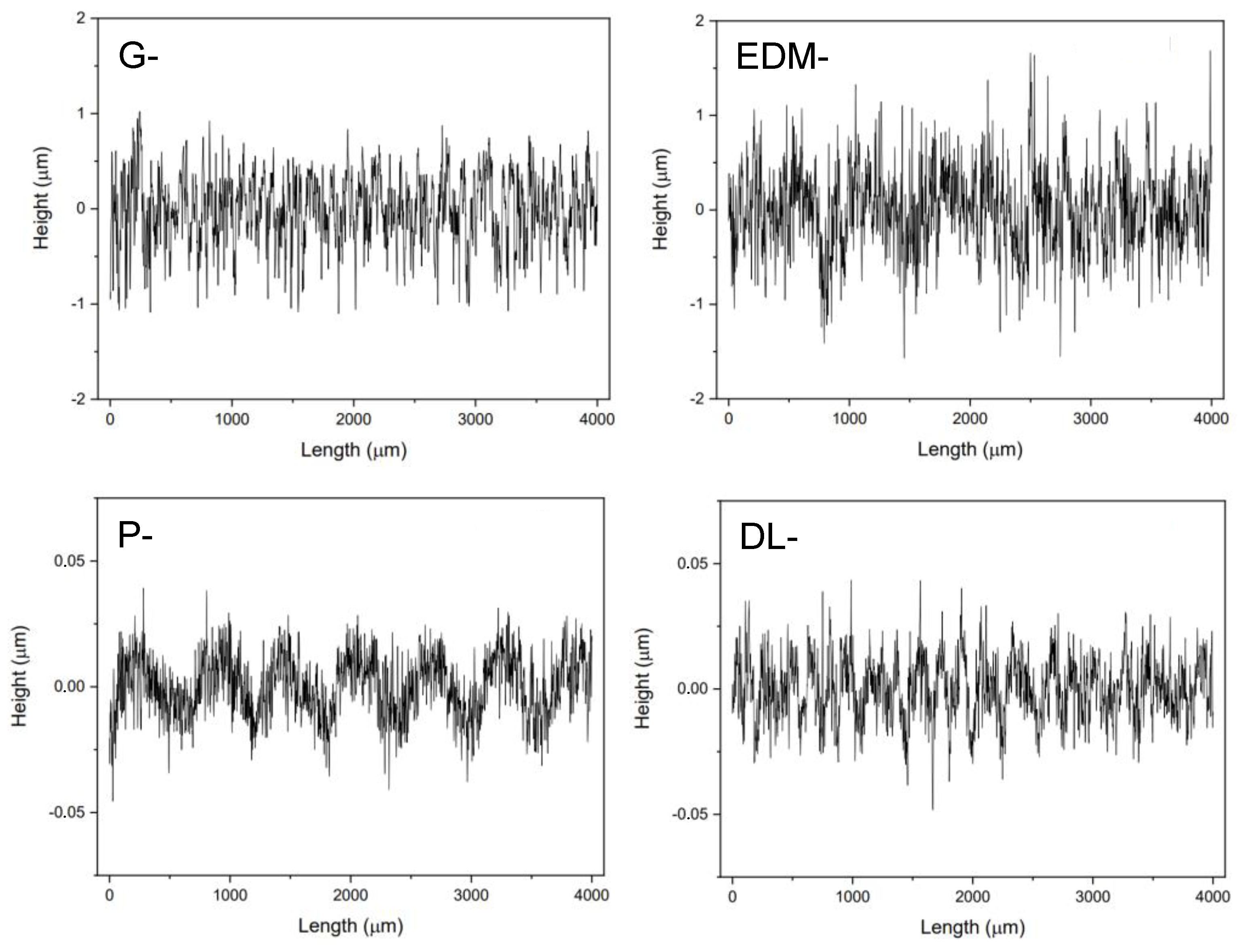
2.3. Surface Characterization

The surface final roughness values of the resulting topographies states were measured by the S neox Five Axis optical profiler (Sensofar Metrology, Sensofar, Terrassa, Spain) following the ISO 25178-600:2019 standard [25]. Data included average roughness, maximum peak to valley height of the profile, and skewness of asymmetry of the profile represented as Ra, Rz and Rsk, respectively, and listed in Table 1. Furthermore, the Ra profile for each investigated surface state is presented in Figure 1. As depicted, the G- and DL- states presents a homogeneous Ra evolution, while for the EDM- and P- states a texture at the surface level is clearly visible due to the post-processing process employed. Finally, as it can be seen; the heigh profile for the G- and EDM- states is higher than for the P- and DL- state in agreement with the information summarized in Table 1.
Microstructural and surface finish scenarios for the different surface states were recorded by means of field-emission scanning electron microscopy (FE-SEM, Carl Zeiss Neon 40, Zeiss Group, Oberkochen, Germany), which was employed in order to observe general appearance, topographical features and surface damage right before and after the post-processing process. Aiming to obtain detailed information of the sub-surface, cross-sections were prepared by means of a Focused Ion Beam (FIB, Carl Zeiss Neon 40, Zeiss Group, Oberkochen, Germany) using a Ga+ source. Prior to FIB milling for the G- state, a protective thin platinum layer was deposited on the region of interest in order to protect the pre-existing damaged layer. Current as well as acceleration voltage were continuously decreased down to a final polishing stage at 500 pA and 30 kV.
The X-ray diffraction (XRD) technique was used to determine residual stresses (σ) for the different surface states. In the particular case of the G- state, compressive residual stresses were calculated on the perpendicular grinding direction, since they are higher compared with the parallel ones [26]. The equipment used was PANalytical Empyrean (PANalytical, Almelo, The Netherlands), which has been operated with Cr Kα radiation at 40 kV and 40 mA. In order to confine the X-ray penetration depth inside the thickness of the superficial affected zone subjected to compressive residual stresses, a low 2θ peak was used. The height error associated with small 2θ tilted angles was reduced using a parallel plate collimator with 0.27° divergence acceptance on the secondary side. Residual stresses were measured with respect to the (200) reflex at 2θ = 74.9°, with 7χ angles (equidistance in sin2Ψ) from 0 to 70°. Furthermore, the analysis was performed with PANalytical Stress Plus software v.3.0 (PANalytical, Almelo, The Netherlands) using the sin2Ψ method and by using X-ray elastic constants of S1 = −0.36 TPa−1 and 1 2 S2 = 2.23 TPa−1.

2.4. Hardness and Indentation Fracture Toughness

To determine the Vickers hardness (HV) at the macroscopic level and to establish the minimum critical load (Pc) at which cracks initiate at the edge of the residual imprint, three indentations were performed for each surface state to achieve statistical significance. These indentations were conducted at different applied loads of 5, 10, 20, 30, 40 and 50 kgf. The indentation fracture toughness (KIC) was determined by measuring the length of cracks emanating from the corners of the residual Vickers imprints.
The applied load selected to determine the KIC was carefully chosen to ensure well-developed crack systems, specifically with a diagonal imprint length exceeding 20 µm and c ≥ 2a [27], where c represents the crack length measured from the center of the residual imprint, and a is half of the imprint diameter. The calculation of KIC was based on the equation proposed by Anstis et al. [27] (see Equation (1)), considering half-penny cracks with a c/a ratio greater than 2.5 [28,29]. Residual imprints as well as a magnification at the edge of the imprint were inspected by FESEM to ensure a precise measurements and reliable data interpretation.
K I C = 0.016 · E H 1 2 · P c 3 2
where P denotes the applied load, ensuring that the diagonal length of imprints exceeds 20 µm and satisfies the condition c ≥ 2a [28,29]). Here, c is the crack length measured from the center of the residual imprint, H represents the Vickers hardness, and E is the Young’s modulus of the superficial state. Given the diverse surface states of the investigated specimen, E for the composite material (deformed layer affected by the superficial state + bulk WC-C material) was determined using the nanoindentation technique under displacement control mode, with a maximum penetration of 2000 nm (or until reaching the maximum loading cell of approximately 650 mN). A Nanoindenter XP (MTS, KLA Tencor, Milpitas, CA, USA) was used with a continuous stiffness module (CSM) and equipped with a Berkovich diamond tip indenter. The indenter tip was carefully calibrated using a standard Fused Silica with a well-known Young’s modulus of 72 GPa [30].
The strain rate was held constant and equal to 0.05 s−1. Data obtained from the experiments were treated using the Oliver and Pharr method [30,31]. A total of sixteen imprints for each state were conducted to statistical significance. The spatial arrangement between imprints was maintained at a constant distance of 20 µm, to avoid any overlapping effect.

2.5. Evaluation of Damage Induced by Conical Indentation

Mechanical contact response for the different surface conditions was assessed by using a conical diamond indenter, featuring a tip radius of 0.2 mm and a spherical head angle of 120°. This evaluation was conducted under discrete applied loads (P) within the 294–490 N range. The selection of this load range was deliberate, as it ensured indentation imprints were significantly deeper than the thickness of the subsurface layer affected by each examined superficial state.
Residual imprints were inspected by means of FESEM to ensure an accurate observation of the main damage mechanisms induced under different stress fields.

3. Results and Discussion

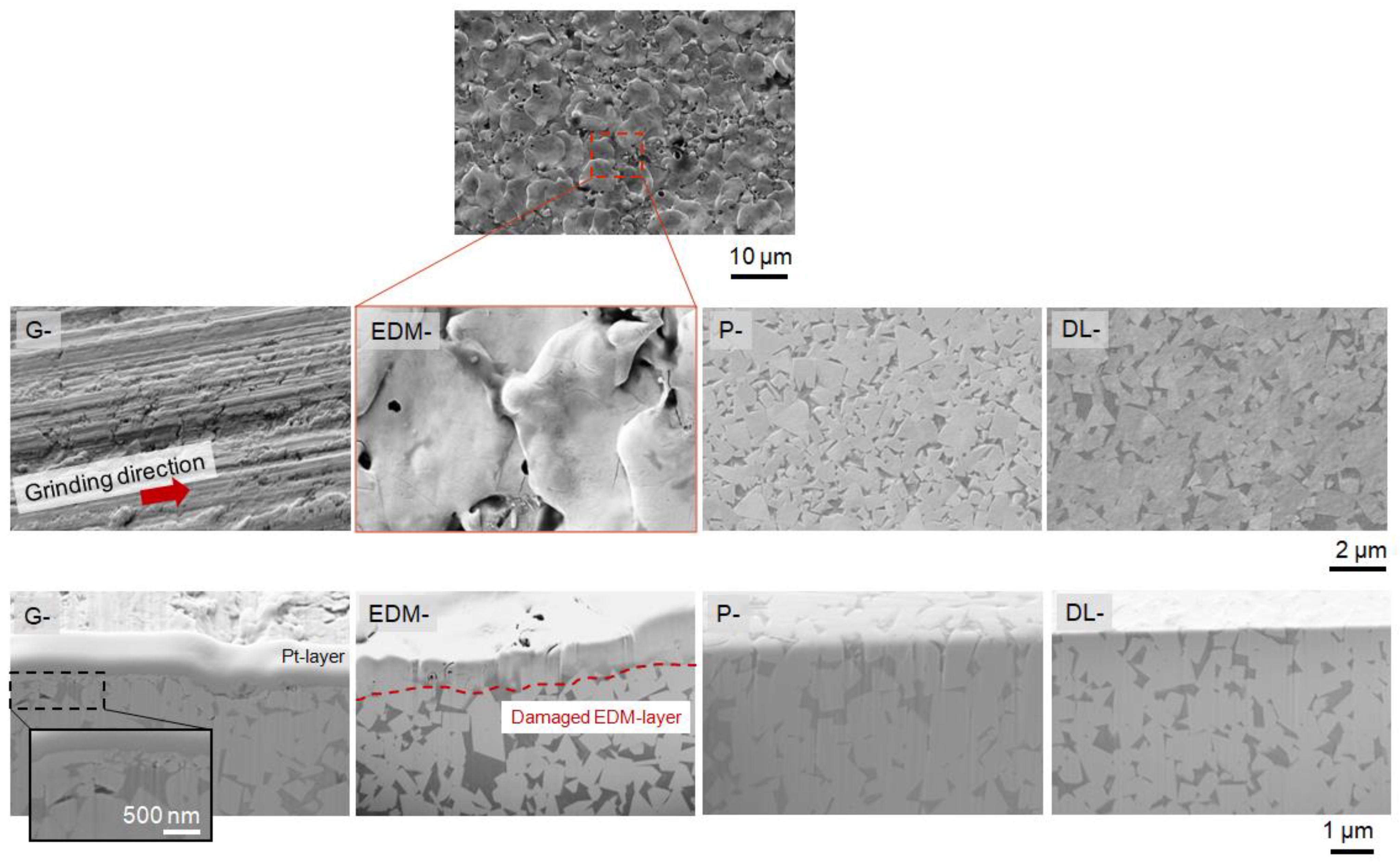
3.1. Microstructural Characterization

Figure 2 shows the FESEM micrographs of the superficial texture (top) as well as the FIB cross-section near the surface (bottom) for the different investigated states. Cross-section micrographs yield information about the near-surface state (i.e., remaining defects induced during the post-processing process, e.g., cracks and voids).
The FESEM micrograph for the G-specimen clearly shows the grinding direction lines. Moreover, the FIB cross-section micrograph presents a heterogeneous deformed layer of approximately 500 nm. It mainly contains cracks, voids and fragmentation of the ceramic phase as it could be seen with the black dashed line. On the other hand, the EDM- sample also presents a highly modified surface. By a FIB cross-section, it is possible to observe an unaffected heterogeneous EDM-layer of approximately 1.3 ± 0.4 µm. This layer contains microcracks, voids, pores and oxides in agreement with [17].
Meanwhile, the resulting SEM microstructure for P- and DL- specimens does not significantly differ. However, analyzing by FIB cross-section, it is possible to observe, for the P- sample, a small difference in height between both constitutive phases due to the difference in their chemical and crystallographic nature, being approximately several nanometers in height. Finally, the DL- state exhibits a homogeneous and smooth surface between constitutive phases, as depicted on the FIB cross-section micrograph.

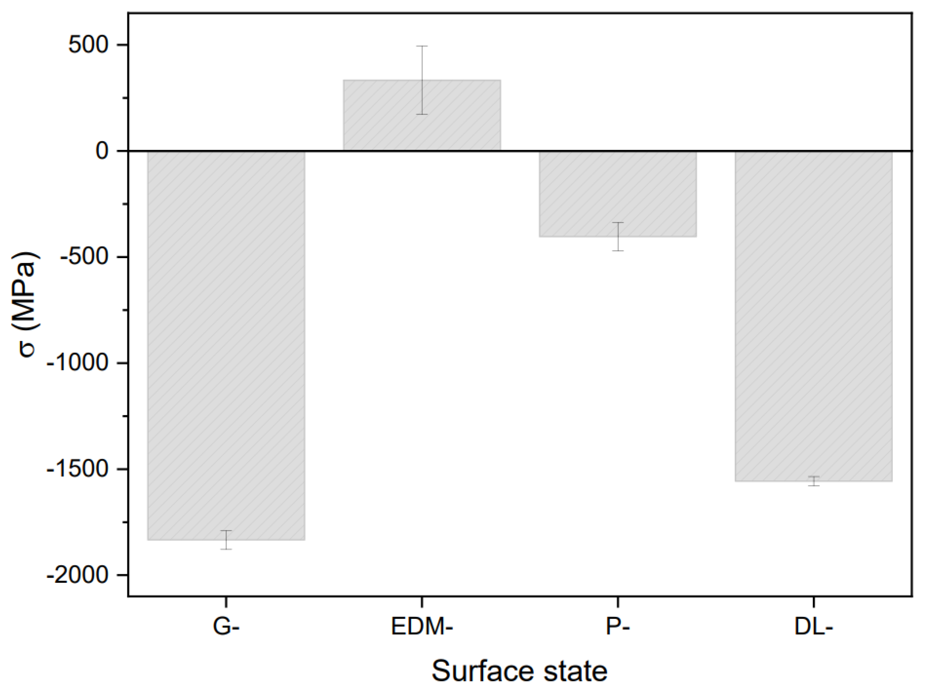
3.2. Surface Residual Stresses

Figure 3 shows the residual stresses (σ) determined for the different investigated states. As reported in previous study [16], G- induces a field of compressive residual stresses (σcomp) at a surface level of approximately –1.8 ± 0.1 MPa. As expected, after a polishing step, the σ recorded for the P- sample has been reduced by approximately 75% regarding the initial G value, in concordance with [16]. This fact is ascribed to the removal material associated with the polishing process, which removes a layer of several tens of micrometers, where the σcomp are confined. However, when a G- specimen is polished using DryLyte® technology, the reduction in the initial σcomp is more limited, i.e., approximately 15%. This fact is due to the dry-electrolyte only interacting with the roughness peaks [17], removing less material during the polishing process than a conventional P- technique, letting to preserve the geometry and tolerance of the workpiece. In this case, the DL- leads to peak removal of the roughness preserving the σcomp in concordance with the data provided by Yang et al. [18]. Furthermore, the degree of roughness for the DL- state is similar to those obtained for the P- state (Table 1), while the degree of remaining σcomp is approximately 60% higher. On the other hand, it is well established that EDM-treatment induces a field of tensile residual stresses (σtensile) in nature [16], in contrast with σcomp for the other investigated states. A high value of the σtensile for the EDM-state leads to substantial degradation of the surface integrity in terms of flexural fatigue, hardness, fracture, wear, and scratch resistance [16,17].

3.3. Mechanical Properties under Different Stress Fields

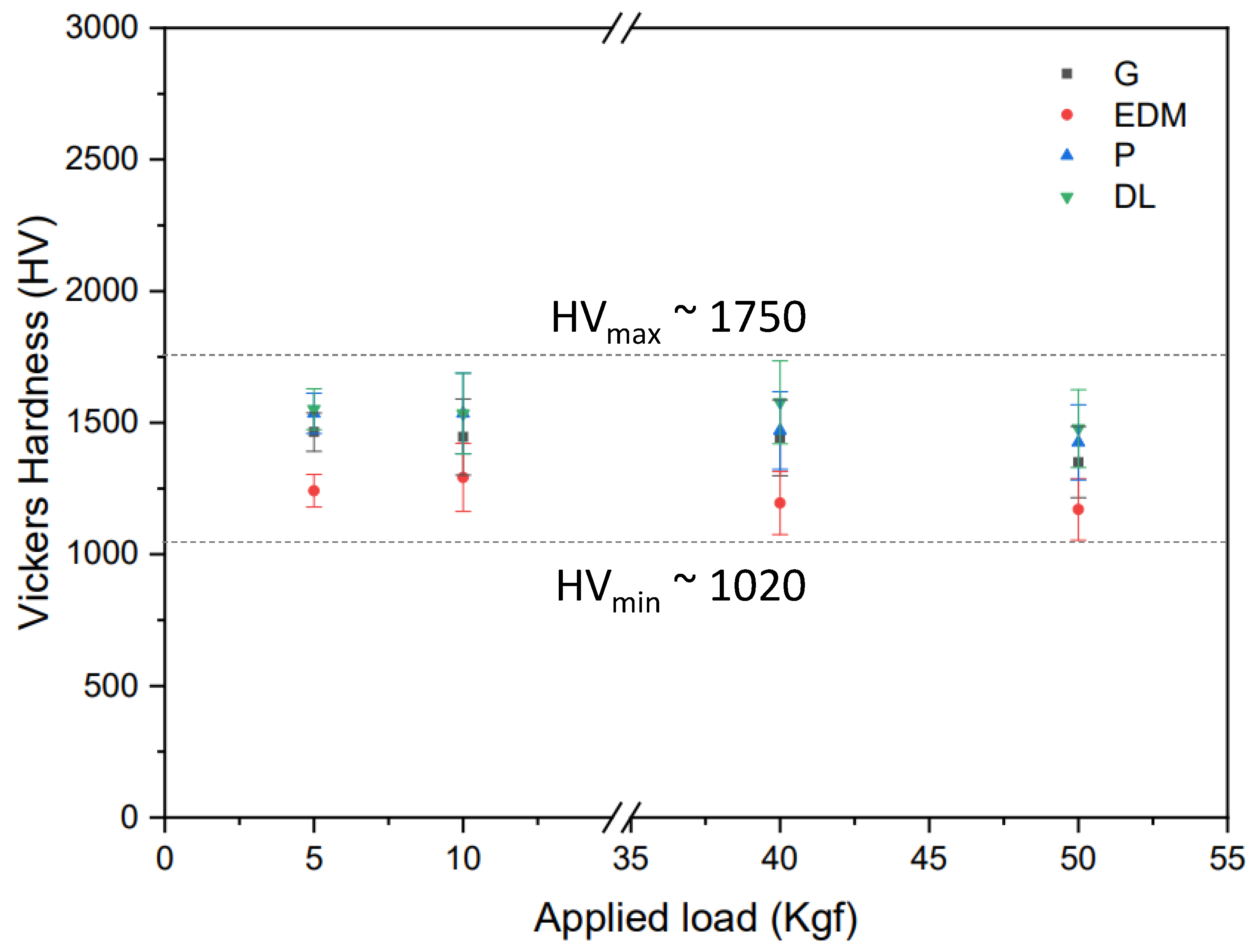
3.3.1. Hardness and Fracture Toughness

Figure 4 exhibits the evolution of the Vickers hardness (HV) as a function of the applied load for the different surface states investigated here. The standard deviations, also shown on the graph, result from an average on different investigated applied load. A non-indentation size effect (ISE) is observed on the hardness versus the applied load representation, due to it remains stable for the range of the investigated applied loads [32]. This finding highlights that the HV remains constant for the investigated surface states and range of applied loads. This result is in concordance with the preliminary research reported by Roebuk et al. [33] and Duszovà et al. [34] on WC-Co materials, which do not present scale or size effects for an applied load higher than 4 mN (or approximately 200 nm of maximum displacement into surface). Furthermore, the HV values appear to remain relatively constant. This observation suggests that the flow stress induced on the investigated post-processing state is uniquely related to the strain at that point and is unrelated to any strain gradient induced at the investigated applied loads [35,36].
The investigated applied loads resulted in an extensive plastic field and a residual imprint ranging from several micrometers to hundreds of micrometers for the imprints conducted at 5 and 50 kgf, respectively. Therefore, the induced stress field cannot be confined to the superficial microstructural deformed layer since the plastic field is larger than its thickness, which is only hundreds of nanometers as shown in Figure 2. Although the deformation field cannot be confined to the surface layer, HV results are slightly affected by microstructural changes induced at the surface level and appreciated in Figure 4 and summarized in Table 2.
Moreover, the data associated with the EDM-state reveal the lowest value of approximately 1241 ± 62 HV5. This may be linked to the distinct chemical nature of the EDM-layer and the presence of a high number of defects, such as voids. Both factors contribute to hardness reduction due to the dissipation of the plastic stress field induced during the indentation process.
It is noteworthy that the HV for the G-, EDM- and P- specimens is in concordance with the values reported in the literature [37]. However, the HV data do not exhibit significant differences in terms of surface integrity at the superficial level. This lack of distinction is attributed to the inherent challenge of confining the induced stress field in the deformed or affected layer.
To gain insights into the primary plastic deformation mechanisms, top-view images of the residual imprints resulting from sharp indentation processes were acquired using a Vickers diamond tip indenter under various applied loads (Figure 5). The black arrow highlights the minimum load for each investigated state, where a crack emanated from the corner of the residual imprint.
As expected, the crack propagation for the G- and EDM- specimens mainly due to the deformed superficial layer’s stress state and chemical nature, block the initiation and propagation of the crack under sharp stress fields at loads lower than 40 kgf. In contrast, the DL state only exhibits a greater hardness value but enhances toughness in terms of crack propagation compared to the P state due to the presence of compressive residual stresses of approximately −1.5 GPa (Figure 3).
Figure 6 exhibits a top-view FESEM magnification of the region delimited with a white dash rectangle presented in Figure 5, where the initial crack generation at different critical loads (Pc), depending on the superficial state, is visible at the edge of the residual imprint. Notably, the crack length at Pc does not conform to the requirements presented in [28,29], particularly for the G- and EDM- states. In light of these considerations, the KIC was assessed at an applied load of 50 kgf only for the P- and DL- states and the main measured values to estimate the KIC using Equation (1) are summarized in Table 2.
As showed in Table 2, despite the HV remaining unaltered along the investigated applied loads, the composite character of the superficial deformed layer and the WC-Co bulk material allows for tuning its surface integrity. This phenomenon may be associated with the different superficial states, leading to alterations in residual stresses, chemical nature or composition, WC particle size, and roughness. From a damage perspective, these changes have implications for the workpiece lifespan.
As expected, no discernible difference is observed between the P- and DL- state at the applied load levels investigated. Both hardness and indentation fracture toughness remain constant and in concordance with the results dispersedly reported in the literature for WC-Co with a 10 wt.% of the metallic Co binder with a submicron particle side for the ceramic phase and summarized in [38].

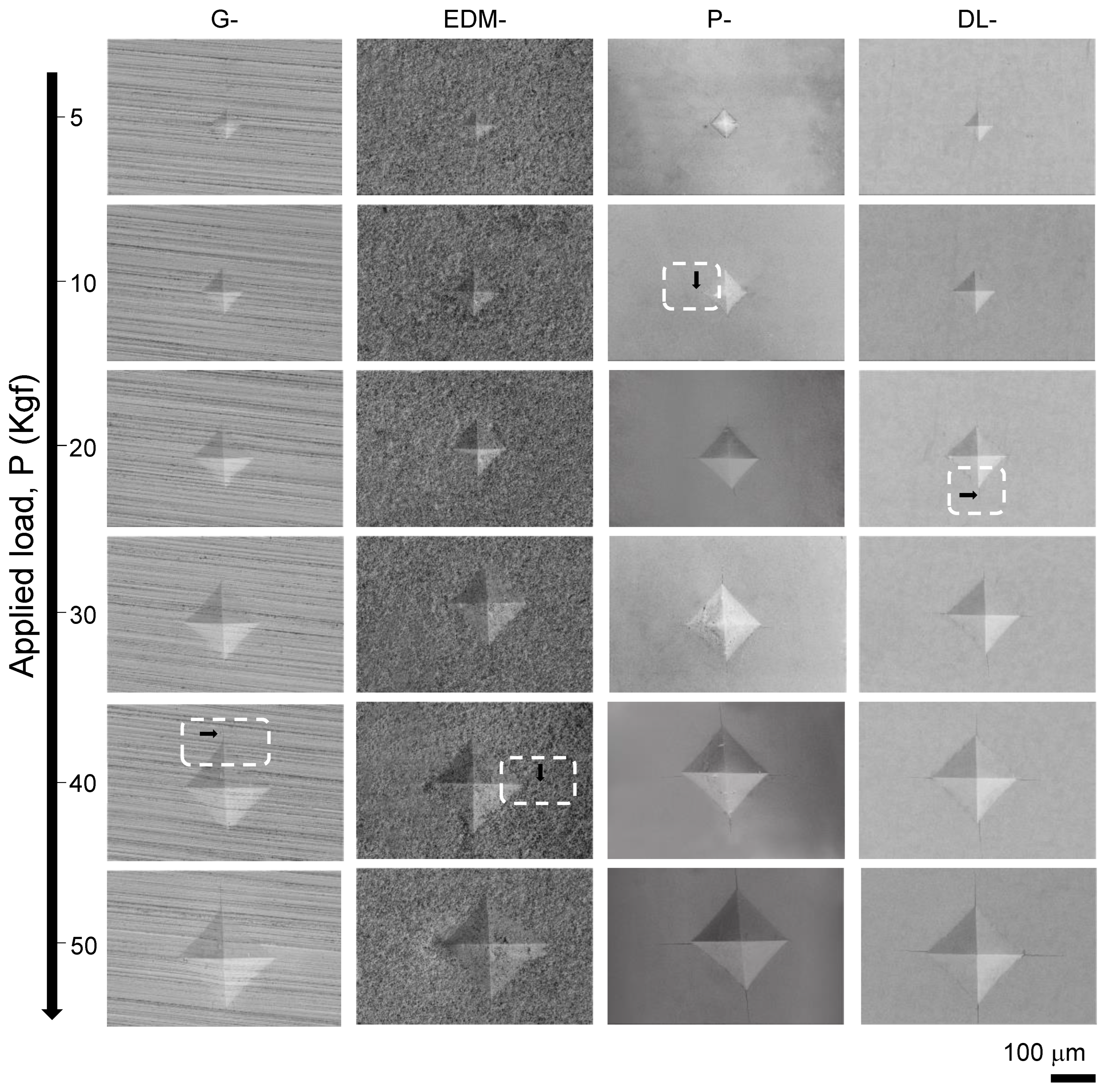
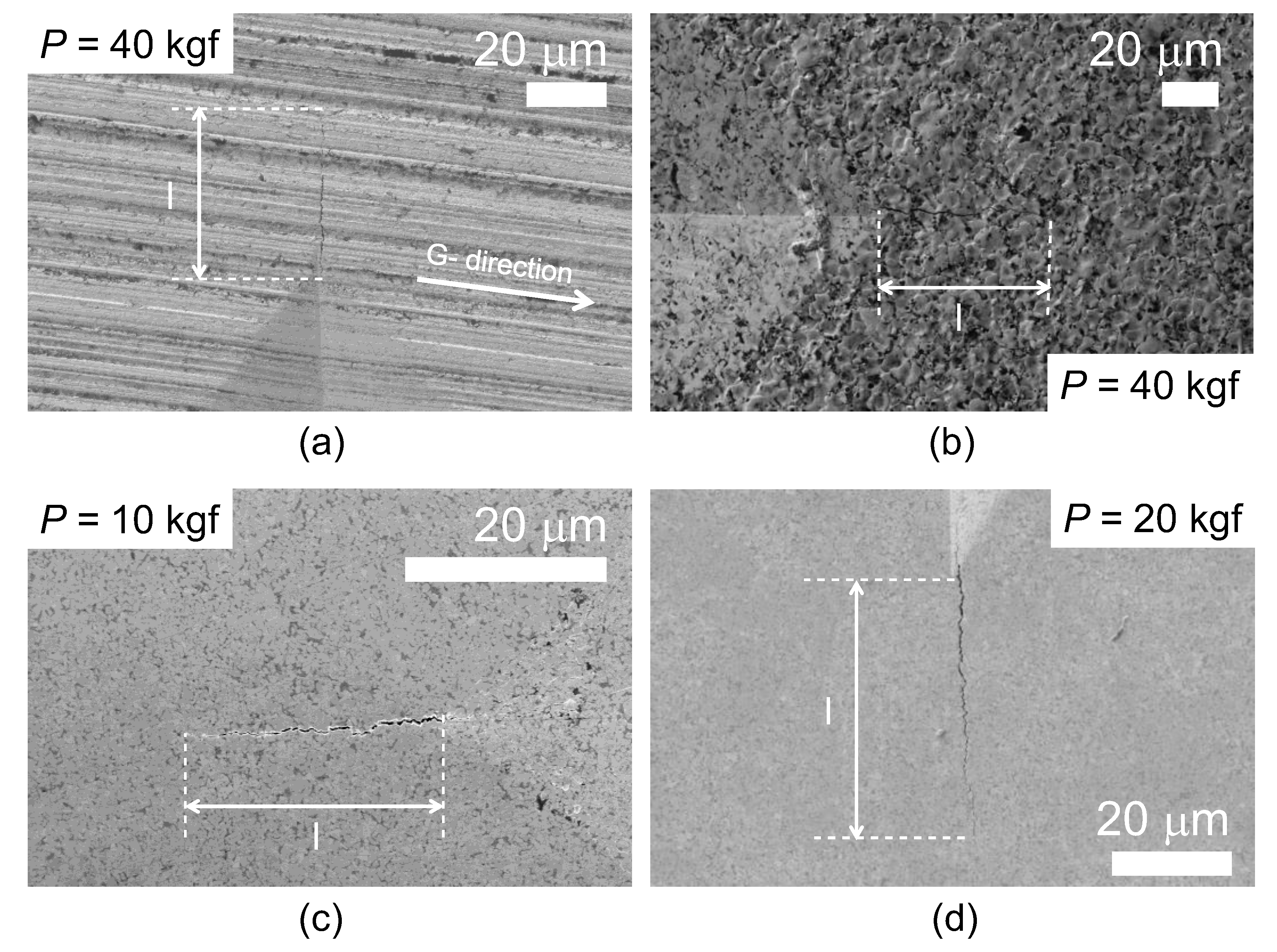
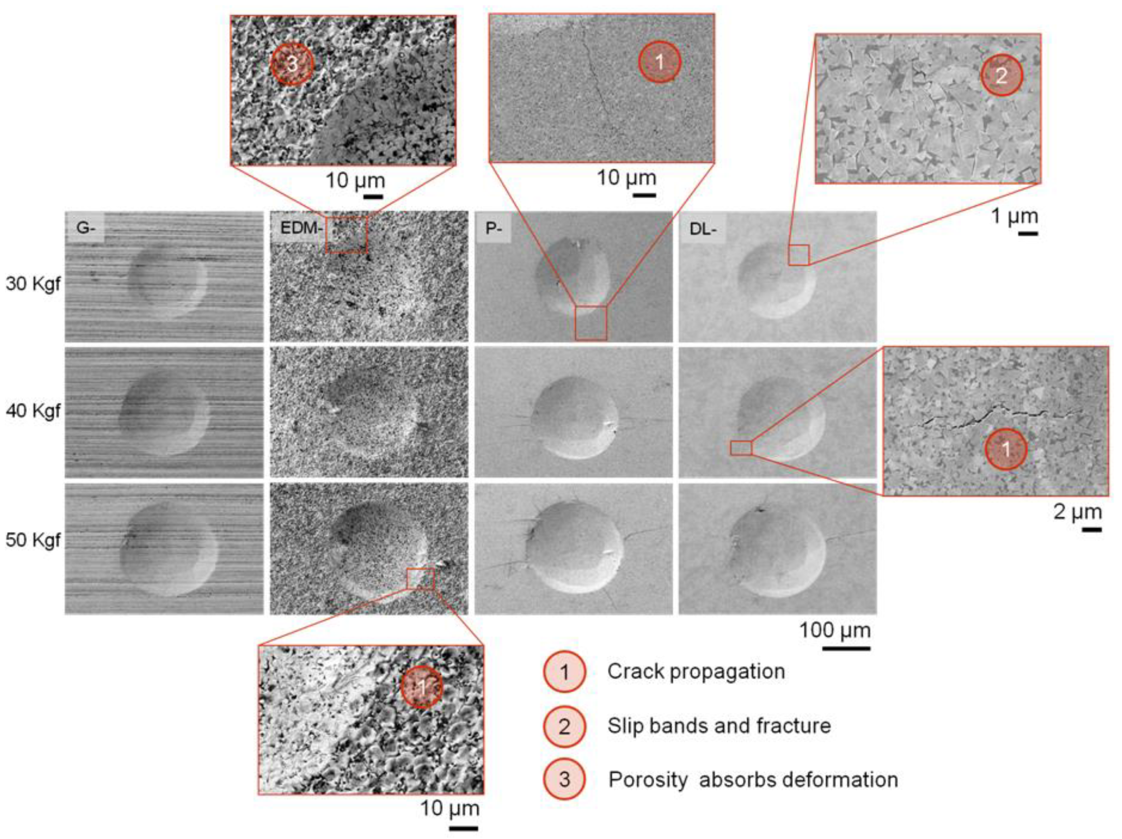
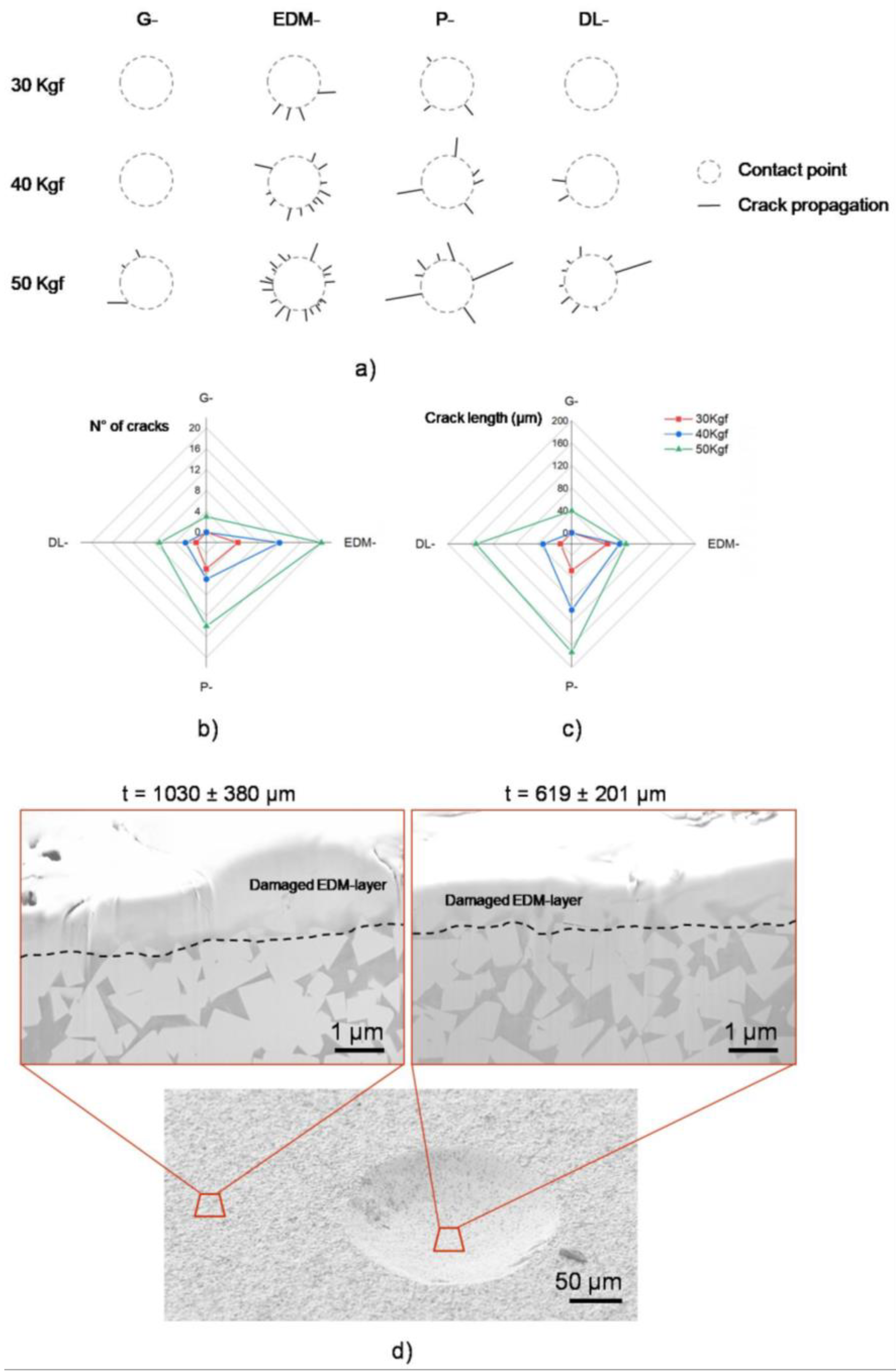
3.3.2. Contact Damage Maps as a Function of the Applied Load

Blunt indentation has shown to be a powerful tool for surface integrity characterization of hard and super-hard materials [38]. Representative FESEM micrographs and damage scenarios for the different superficial states investigated here by means of cone-shape indentations resulting from applying different load levels are depicted in Figure 7. At first glance, it can be seen that damage, mainly cracks, have been generated in practically all cases. However, the critical load (Pc) for damage to appear significantly depends on the surface finish. Intending to clarify this, Figure 8a presents a schematic representation of the evolution of the damage generated as a function of applied load.
Furthermore, the number of cracks generated and their maximum length achieved under different applied load values as a function of the surface states are presented in Figure 8b and 8c, respectively. They allow to evidence that the G- state presents the higher crack resistance, with P = 490 N the lowest Pc to induce cracks at the surface. This fact must be associated with the large σcomp, which are able to delay the emergence of cracks. Moreover, due to the surface texture resulting from grinding, the generated cracks are complicated to be distinguish. Within this context, G condition exhibits the higher contact damage resistance in terms of Pc as well as the length of the longest crack at the surface level.
Regarding the polished samples, it is evidenced that DL- state shows a higher Pc value than the P- one. This fact should again be linked to the remnant σcomp for the former, which is about 60% higher than for the latter. Comparing the residual imprints at the minimum applied load (Figure 3), it is clearly seen that the DL- sample does not present crack propagation, while the P- sample does. However, slip bands and inter- fracture mechanisms are observed on the DL- sample. Moreover, the behavior is similar for both conditions for higher applied loads. This phenomenon is discerned in Figure 8c.
Finally, the EDM- surface has a completely different behavior. Here, as the applied load increases, the generation of cracks prevails over further extension of them (Figure 8b,c). Attempting to understand this experimental finding, two FIB cross-sections were inspected: one inside (region where the maximum induced stress is concentrated) and the other outside (region where the stress is practically negligible) of the residual imprint conducted at 490 N (Figure 8d). The stress field induced during the conical indentation process deforms almost half of the initial EDM layer, reaching a final value of approximately 0.6 (±0.2) µm. Furthermore, the defects confined in the EDM-layer, mainly voids and thin EDM-layer with a metallic nature, lead to the absorption of the induced plastic field. Consequently, it avoids crack path propagation, showing a less brittle-like behavior.

4. Conclusions

This study compares the microstructure, mechanical properties, and compressive residual stresses of four commonly presented superficial states in the cemented carbide industry. The research findings provide insights into the main conclusions obtained from this investigation. These states include ground, electrical discharge machined, polished, and dry-electrochemically polished using DryLyte® technology.
  • Microstructural and surface/subsurface scenarios evaluated for the four final surface states show that the G- and EDM- samples exhibit higher roughness and more pronounced residual damage, confined near the surface, than both polished samples. However, in the case of the G- sample, it is counterbalanced in the former by the significantly high compressive residual stresses induced, yielding this surface finish condition the highest mechanical response under contact loading, as assessed by means of conical indentation.
  • Roughness and residual damage issues of ground samples are overcome by subsequent material removal through polishing. In this regard, the effectiveness of DL- state, as compared to the P- one, is highlighted because less material is removed to achieve mirror-like roughness; thus, the compressive residual stresses referred to are partly retained in the former.
  • Cone-shaped indentation has been successfully implemented to assess the contact damage response of different superficial states in the cemented carbide specimens. It is validated to be a suitable technique for inducing controlled damage at the superficial level and evaluating the damage scenario as a function of the applied load.
  • DryLyte® technology is an interesting post-processing technique for surface finishing requirements because it allows the tolerance of the desired workpiece to be preserved together with minimum surface roughness levels, while maintaining a large amount of the compressive stress state introduced during grinding.

Author Contributions

Conceptualization, G.R.-P., J.J.R. and L.L.; methodology, G.R.-P.; validation, J.J.R. and L.L.; investigation, G.R.-P. and S.S.; resources, J.J.R., L.L. and F.M.; writing—original draft preparation, G.R.-P.; writing—review and editing, G.R.-P., S.S., L.L., F.M. and J.J.R.; visualization, G.R.-P.; supervision, J.J.R. and L.L.; project administration, J.J.R. All authors have read and agreed to the published version of the manuscript.

Funding

S. Slawik and F. Mücklich would like to thank the funding received for the Deutsche Forschungsgemeinschaft (DFG) to partly acquire the X-Ray diffractometer (project number 280248231). Finally, G. Riu-Perdrix acknowledges funding received through Ministerio de Ciencia e Innovación y la Agencia Estatal de Investigación (AEI) de España (Grant Number DIN2021-011846).

Data Availability Statement

All data generated or analyzed during this study are included in this published article.

Conflicts of Interest

Authors Guiomar Riu-Perdrix and Joan Josep Roa were employed by the company Steros GPA Innovative S.L. The remaining authors declare that the research was conducted in the absence of any commercial or financial relationships that could be construed as a potential conflict of interest.

References

  1. Prakash, L. Fundaments and general applications of hardmetals. In Comprehensive Hard Materials, 1st ed.; Mari, D., Llanes, L., Eds.; Elsevier: Kidlington, UK, 2014; Volume 1, pp. 29–90. [Google Scholar] [CrossRef]
  2. García, J.; Collado Ciprés, V.; Blomqvist, A.; Kaplan, B. Cemented carbide microstructures: A review. Int. J. Refract. Met. Hard Mater. 2019, 80, 40–68. [Google Scholar] [CrossRef]
  3. Byrne, G.; Dornfeld, D.; Denkena, B. Advancing cutting technology. CIRP Ann. Manuf. Technol. 2003, 52, 483–507. [Google Scholar] [CrossRef]
  4. Hao, X.; Li, H.; Yang, Y.; Xiao, S.; Song, X.; Li, L. Experiment on cutting performance of textured cemented carbide tools with various wettability levels. Int. J. Adv. Manuf. Technol. 2019, 103, 757. [Google Scholar] [CrossRef]
  5. Bouzakis, K.D.; Micjailidis, N.; Skordaris, G.; Bouzakis, E.; Biermann, D.; M’Saoubi, R. Cutting with coated tools: Coating technologies, characterization methods and performance optimization. CIRP Ann. Manuf. Technol. 2012, 61, 703–723. [Google Scholar] [CrossRef]
  6. M’Saoubi, R.; Outeiro, J.C.; Chandrasekaran, H.; Dillon, O.W., Jr.; Jawahir, I.S. A review of surface integrity in machining and its impact on functional performance and life of machined products. Int. J. Sustain. Manuf. 2008, 1, 203–236. [Google Scholar] [CrossRef]
  7. Sigl, S.S.; Exner, H.E. Experimental study of the mechanics of fracture in WC-Co alloys. Metal. Mat. Trans. 1987, 18, 1299. [Google Scholar] [CrossRef]
  8. Yang, N.; Zong, W.; Li, Z.; Sun, T. The dependency of diamond lapping surface morphology on crystal orientation. Int. J. Adv. Man. Technol. 2014, 77, 1029. [Google Scholar] [CrossRef]
  9. Malkin, S.; Guo, C. Grinding Technology: Theory and Application of Machining with Abrasives, 2nd ed.; Industrial Press Inc.: New York, NY, USA, 2008. [Google Scholar]
  10. Marinescu, I.D.; Tonshoff, H.K.; Inaski, I. Handbook of Ceramic Grinding and Polishing; Noyec Publications/William Andrew Publishing, L.L.C: New York, NY, USA, 1998. [Google Scholar]
  11. Hegeman, J.B.J.W.; De Hosson, J.T.M.; De With, G. Ginding of WC-Co hardmetals. Wear 2001, 248, 187–196. [Google Scholar] [CrossRef]
  12. Ho, K.H.; Newman, S.T. State of the art electrical discharge machining (EDM). Int. J. Mach. Tool Manuf. 2003, 43, 1287–1300. [Google Scholar] [CrossRef]
  13. Jahan, M.P.; Rahman, M.; Wong, Y.S. A review on the conventional and micro-electrodischarge machining of tungsten carbide. Int. J. Mach. Tool Manuf. 2011, 51, 837–858. [Google Scholar] [CrossRef]
  14. Bhaduria, G.; Jha, S.K.; Roy, B.N.; Dhakry, N.S. Electrical-Discharge Machining of Tungsten Carbide (WC) and its composites (WC-Co)A Review. Mat. Today Proc. 2018, 5, 24760–24769. [Google Scholar] [CrossRef]
  15. Wu, Y.-Y.; Huang, T.-W.; Sheu, D.-Y. Desktop Micro-EDM System for High-Aspect Ratio Micro-Hole Drilling in Tungsten Cemented Carbide by Cut-Side Micro-Tool. Micromachines 2020, 11, 675. [Google Scholar] [CrossRef] [PubMed]
  16. Bonny, K.; Beats, P.D.; Quintelier, J.; Vleugels, J.; Jiang, D.; Van der Biest, O.; Lauwers, B.; Liu, W. Surface finshing: Impact on tribological characteristics of WC-Co hardmetals. Tribol. Int. 2009, 43, 40–45. [Google Scholar] [CrossRef]
  17. Llanes, L.; Casas, B.; Idañez, E.; Marsal, M.; Anglada, M. Surface integrity effects on the fracture resistance of electrical-discharge-machined WC-Co cemented carbides. J. Am. Ceram. Soc. 2003, 87, 687–1693. [Google Scholar] [CrossRef]
  18. Riu, G.; Weil, D.; Llanes, L.; Johanns, K.E.; Oliver, W.C.; Roa, J.J. Surface integrity of new dry-electropolishing technology on WC-Co cemented carbide. Procedia CIRP 2022, 108, 543–548. [Google Scholar] [CrossRef]
  19. Crittenden, J.C.; Truseel, R.R.; Hand, D.W.; Howe, K.J.; Tchobanoglous, G. MWH’s Water Treatment: Principles and Design, 3rd ed.; John Wiley & Sons: Hoboken, NJ, USA, 2012. [Google Scholar] [CrossRef]
  20. Fathi, M.B.; Rezai, B.; Alamdari, E.K.; Alorro, R.D. Mechanisms and equilibrium modeling of Re and Mo adsorption on a gel type strong base anion resin. Russ. J. Appl. Chemis. 2017, 90, 1504. [Google Scholar] [CrossRef]
  21. Roebuck, B.; Almond, E.A. Deformation and fracture processes and the physical metallurgy of WC-Co hardmetals. Int. Mater. Rev. 1988, 33, 90. [Google Scholar] [CrossRef]
  22. Torres, Y. Comportamiento a Fractura y Fatiga de Carburos Cementados WC-Co. Ph.D. Thesis, Universitat Politècnica de Catalunya, Barcelona, Spain, 2002. [Google Scholar]
  23. Coureaux, D. Comportamiento Mecánico de Carburos Cementados WC-Co: Influencia de la Microestructura en la Resistencia a la Fractura, la Sensibilidad a la Fatiga y la Tolerancia al Daño Inducido Bajo Solicitaciones de Contacto. Ph.D. Thesis, Universitat Politècnica de Catalunya, Barcelona, Spain, 2012. [Google Scholar]
  24. Exner, H.E. Physical and chemical nature of cemented carbides. Int. Met. Rev. 1979, 4, 1149. [Google Scholar] [CrossRef]
  25. ISO 25178-600; Geometrical Product Specifications (GPS)—Surface Texture: Areal—Part 600: Metrological Characteristics for areal Topography Measuring Methods. International Organization for Standardization: London, UK, 2019.
  26. Riu, G.; Monclús, M.A.; Slawik, S.; Cinca, N.; Tarrés, E.; Mücklich, F.; Llanes, L.; Molina-Aldareguia, J.M.; Guitar, M.A.; Roa, J.J. Microstructural and mechanical properties at the submicrometric length scale under service-like working conditions on ground WC-Co grades. Int. J. Refract. Met. Hard Mater. 2023, 116, 106359. [Google Scholar] [CrossRef]
  27. Anstis, G.R.; Chantikul, P.; Lawn, B.R.; Marshall, D.B. A critical evaluation of indentation techniques for measuring fracture toughness: I, direct crack measurements. J. Am. Ceram. Soc. 1981, 64, 533. [Google Scholar] [CrossRef]
  28. Fett, T. An analysis of the residual stress intensity factor of vickers indentation cracks. Eng. Fract. Mech. 1995, 52, 773. [Google Scholar] [CrossRef]
  29. Moradkhani, A.; Baharvandi, H.; Tajdari, M.; Latifi, H.; Martikainen, J. Determination of fracture toughness using the area of micro-crack tracks left in brittle materials by Vickers indentation test. J. Adv. Ceram. 2013, 2, 87. [Google Scholar] [CrossRef]
  30. Oliver, W.C.; Pharr, G.M. An improved technique for determining hardness and elastic modulus using load and displacement sensing indentation experiments. J. Mater. Res. 1992, 7, 1564. [Google Scholar] [CrossRef]
  31. Oliver, W.C.; Pharr, G.M. Measurement of hardness and elastic modulus by instrumented indentation: Advances in understanding and refinements to methodology. J. Mater. Res. 2004, 19, 3. [Google Scholar] [CrossRef]
  32. Nix, W.D.; Gao, H. Indentation size effects in crystalline materials: A law for strain gradient plasticity. J. Mech. Phys. Solids. 1998, 46, 411–425. [Google Scholar] [CrossRef]
  33. Roebuck, B.; Klose, P.; Mingard, K.P. Hardness of hexagonal tungsten carbide crystals as a function of orientation. Acta Mater. 2012, 60, 6131–6143. [Google Scholar] [CrossRef]
  34. Duszová, A.; Halgas, R.; Bl’anda, M.; Hvizdos, P.; Lofaj, F.; Dusza, J.; Morgiel, J. Nanoindentation of WC-Co hardmetal. J. Eur. Ceram. Soc. 2013, 33, 2227–2232. [Google Scholar] [CrossRef]
  35. Fischer-Cripps, A.C. Introduction to Contact Mechanics; Springer: New York, NY, USA, 2000; ISBN 0387989145. [Google Scholar]
  36. Fleck, N.A.; Hutchinson, J.W. A reformulation of strain gradient plasticity. J. Mechan. Phys. Sol. 2001, 49, 2245–2271. [Google Scholar] [CrossRef]
  37. Chychko, A.; García, J.; Ciprés, V.C.; Holmström, E.; Blomqvist, A. HV-KIC property charts of cemented carbides: A comprehensive data collection. Int. J. Refract. Met. Hard Mater. 2022, 103, 105763. [Google Scholar] [CrossRef]
  38. Gordon, S.; García-Marro, F.; Rodriguez-Suarez, T.; Roa, J.J.; Jiménez-Piqué, E.; Llanes, L. Spherical indentation of polcrystalline cubic boron nitrade (PcBN): Contact damage evaluation with increasing load and microstructral effects. Int. J. Refract. Met. Hard Mater. 2023, 111, 106115. [Google Scholar] [CrossRef]
Figure 1. Ra profile (height vs. length) for the different investigated states.
Metals 14 00052 g001
Figure 2. FE-SEM (top) and FIB cross-section (bottom) micrographs of the different WC-Co states.
Metals 14 00052 g002
Figure 3. Residual stress representation as a function of surface states investigated here.
Metals 14 00052 g003
Figure 4. Vickers hardness evolution as a function of the investigated applied load for the different surface states investigated here.
Metals 14 00052 g004
Figure 5. Residual Vickers hardness imprints as a function of the investigated applied load for the different surface states investigated. The black rows highlight the crack initiation and a magnification of it is present in Figure 6.
Metals 14 00052 g005
Figure 6. High-magnification FESEM images performed at the edge of the Vickers imprint show the induced radial cracks for the investigated states. (a) G-, (b) EDM-, (c) P- and (d) DL-.
Metals 14 00052 g006
Figure 7. FE-SEM micrographs of the residual spherical indentation imprint as a function of the P obtained for the different investigated surface states.
Metals 14 00052 g007
Figure 8. (a) Schematic representation of the different damage obtained under spherical indentation tests as a function of P, (b,c) radar maps comparing the induced damage for the different superficial states as a function of the number of cracks and crack length, respectively, and (d) a general view (bottom micrograph) of a residual imprint conducted at P = 50 kgf and FIB cross-section (upper micrograph) performed on an EDM- specimen.
Metals 14 00052 g008
Table 1. Summary of the main roughness (Ra, Rz and Rsk) parameters with the related standard deviation for the different surface states studied.
Surface StateRa (µm)Rz (µm)Rsk
G-0.29 ± 0.012.31 ± 0.11−0.35 ± 0.06
EDM-0.33 ± 0.022.98 ± 0.260.23 ± 0.21
P-0.01 ± 0.010.07 ± 0.01−0.02 ± 0.11
DL-0.01 ± 0.010.09 ± 0.01−0.01 ± 0.04
Table 2. Vickers hardness (HV) and indentation fracture toughness (KIC) results from Vickers indentations determined at 50 kgf of the maximum applied load. d is the mean diagonal, l is the crack length measured from the imprint corner, and E is the Young modulus determined by means of the nanoindentation technique and determined at 2000 nm of maximum displacement into the surface.
Surface StateP
Kgf
d
(µm)
l
(µm)
E
(GPa)
HV
(kg·mm−2)
KIC *
(MPa·√m)
G-50164.5436 ± 551443 ± 144♣♣
EDM--209.1232 ± 311195 ± 180♣♣
P--164.989 ± 3 503 ± 101466 ± 15410.5 ± 0.7
DL--165.188 ± 4565 ± 451487 ± 15610.8 ± 0.2
* For KIC calculation using Equation (1), c = l + d/2. ♣ The determination of l for the G- and EDM- states is hindered by two factors: (1) the deformed layer does not lead to propagate and emerge the crack at the investigated loads and (2) the superficial roughness impedes the accurate measurement of the crack length. ♣♣ The KIC for the G- and EDM- states cannot be reliably determined using the indentation method. This is attributed to the inadequately developed crack at the corner of the residual imprint at the maximum applied load, introducing considerable uncertainties and yielding unrealistic data.
Disclaimer/Publisher’s Note: The statements, opinions and data contained in all publications are solely those of the individual author(s) and contributor(s) and not of MDPI and/or the editor(s). MDPI and/or the editor(s) disclaim responsibility for any injury to people or property resulting from any ideas, methods, instructions or products referred to in the content.

