Article

Parameter Optimization in Orbital TIG Welding of SUS 304 Stainless Steel Pipe

by
Pham Son Minh
1,
Van-Thuc Nguyen
1,
Thanh Trung Do
1,
Tran Minh The Uyen
1,
Huynh Do Song Toan
1,
Huynh Thi Tuyet Linh
1 and
Van Thanh Tien Nguyen
2,*
1
Faculty of Mechanical Engineering, Ho Chi Minh City University of Technology and Education, Ho Chi Minh City 71307, Vietnam
2
Faculty of Mechanical Engineering, Industrial University of Ho Chi Minh City, Nguyen Van Bao Street, Ward 4, Go Vap District, Ho Chi Minh City 70000, Vietnam
*
Author to whom correspondence should be addressed.
Metals 2024, 14(1), 5; https://doi.org/10.3390/met14010005
Submission received: 14 November 2023 / Revised: 4 December 2023 / Accepted: 16 December 2023 / Published: 20 December 2023

Abstract

:
The influence of welding angle, welding current, travel speed, pulse time, and torch height on the geometry, macrostructure, and mechanical properties of Tungsten Inert Gas (TIG) orbital welding on an SUS 304 stainless steel pipe is investigated in this study. The results show that an electrode angle of 45° produces better weld joints than angles of 30°, 60°, 90°, and 120°. Furthermore, the electrode angle of 30° results in an acceptable weld width but a low depth of penetration (DOP) value. Welding current and weld speed have a significant impact on heat dispersion during TIG welding of an SUS 304 stainless steel pipe. The high welding current may result in blow-hole flaws, particularly near the conclusion of the welding process when heat is accumulated. A long torch height of 2 mm causes unevenness in the weld joints because the arc may be distorted when compared to shorter torch height cases. The pulse time of 0.2 s is too lengthy for a low-welding current situation because it will generate a small weld pool. As a result, the weld pool solidification process speeds up, and porosity emerges in the weld bead. A pulse time of 0.1 s results in a better weld joint. To avoid blow-hole creation, the welding current should be gradually reduced during the process. In addition, the Taguchi results demonstrate that the welding current has the greatest effect on the ultimate tensile strength (UTS) value, followed by welding speed, pulse time, electrode angle, and torch height. Furthermore, the ideal parameters for the UTS value are an electrode angle of 45°, a torch height of 2.0 mm, a welding current of 174 A, a welding speed of 72 mm/min, and a pulse time of 0.3 s.

1. Introduction

Tungsten Inert Gas (TIG) welding or Gas Tungsten Arc Welding (GTAW) are arc welding technologies in which the electrode does not melt and the welding process is conducted in an inert gas condition [1,2,3]. TIG welding is broadly applied in high alloy steels, stainless steel, and non-ferrous alloys. In particular, the TIG welding technique is also preferred in orbital welding for pipes in food and bio-medical industries [4,5,6]. The pipe’s quality requires high-quality welding to prevent it from leaking, because pipes leaking could lead to contamination, decreased productivity, and toxic dispersal [7,8,9]. Moreover, cleanliness in a condition of no oxidation of the surface of the stainless-steel tubes after welding is also a critical requirement. Therefore, forming gas is very important and affects the cleanliness and depth of penetration (DOP).
Orbital welding is the process of pipe welding in which the welding electrode is rotated around the pipe, and it melts the pipe substrate by the arc to create a welded joint [10,11]. The orbital welding process could be set up automatically; therefore, the welding defects are limited, and the welded joint quality is enhanced. Orbital welding could be modified to fit a specific application. For example, Figueirôa et al. [12] investigated the impact of welding position and parameter in orbital TIG welding of SAE 1020 steel pipe. The results indicated that implementing a pulsed current lead to better welding beads with higher strength and hardness, a wider shape, and a finer microstructure. Li et al. [13] developed a method to monitor and control the welding penetration by analyzing the development of the weld pool. The monitor and control system were successfully applied to create smooth and consistent weld beads. E Silva et al. [14] reported that the TopTIG technique of the GTAW method possesses the advantages of simplicity in operation and trajectory programming. Interestingly, Górka et al. [15] studied the orbital TIG welding of titanium tubes with titanium-clad steel. The research pointed out that the preparation of weld joints could reduce welding defects.
Orbital welding is widely applied to weld stainless steel pipes. For instance, Lothongkum et al. [16] investigated the orbital welding of 316 L steel plates. They proved that increasing the welding speed leads to an improvement in the pulse current. Moreover, increasing the welding speed to more than 6 mm/s gives rise to the formation of slag. In addition, Riffel et al. [17] welded an SUS 304 L stainless steel pipe automatically at a speed of 500 mm/min under the monitor of high-dynamic-range videography. The welded joint was successfully formed without any porosity, discontinuities, or lack of fusion. Kumar et al. [18] increased the penetration depth of the SUS 304 stainless steel pipe by mixing a hybrid flux with SiO2, Al2O3, and TiO2. The hybrid flux also improves the surface quality of the weld bead. Moreover, Niagaj et al. [19] investigated the orbital welding of the SUS 304 stainless steel pipe with a closed welding head. This report indicated that increasing the welding current and the welding speed could increase the penetration quality. However, increasing the welding current and the welding speed gives rise to the formation of defects at positions of 9 h and 12 h. Pradhan et al. [20] conducted both simulation and experiment research to optimize the orbital welding parameter of SUS 304 stainless steel. The authors proved that using ANSYS software could predict reliable responses with minimum errors. Moreover, the report also showed that the most important factors that strongly affect the weld temperature are the current and welding speed. Notably, Engelhard et al. [21] researched the residual welding stress in austenitic stainless steel pipes. The report indicated that to limit the residual stress, the pipe substrate should have a low carbon content of less than 0.03%, and the Nb: C should be greater than 13. Before welding, the pipes should avoid high levels of cold-working, hardening, and tensile residual stress. Additionally, during the welding process, the heat input should be applied at a uniform and low rate to avoid the formation of residual stress. Vänskä et al. [22] applied laser fiber to weld the SUS 304 stainless steel pipes. The tube welding could be formed at a high productivity rate due to the strong laser heat input. Furthermore, the weld bead has a high level of weld width and some oxidation spots on the surface. The bead surface, therefore, should experience a post-processing of pickling to remove the oxidation spots. Baskoro et al. [23] studied the orbital welding process of AISI 304 L stainless steel pipe by optimizing it with the ANOVA and Taguchi methods. During the welding process, the weld bead is created without using additional material. The study indicated that increasing the welding current results in a higher level of weld width and DOP; however, the ultimate tensile strength (UTS) value would be reduced. The influence of the welding sequence and welding current on distortion, mechanical properties, and metallurgical observations in orbital pipe welding with an SS 316 L pipe square butt joints is discussed in Widyianto et al.’s [24] study. The findings demonstrate that with a welding current of 120 A, maximum axial distortion, transverse distortion, ovality, and taper occurred with four sequences of 445 µm, 300 µm, 195 µm, and 275 µm, respectively. The orbital welding process on stainless steel AISI 316 L with various process parameters was investigated experimentally and through finite element simulation by Singh et al. [25]. For temperature distribution during orbital welding, the best input parameters are 40A current, 0.72 mm/s welding speed, and 1.8 mm standoff distance. Elmer et al. [26] studied the impact of sulfur concentration on weld penetration in orbital tube welds of austenitic stainless steel. The weld process specification must precisely describe the sulfur limitations for a particular weld in order to minimize variation in orbital tube junction penetration. Dak et al. [27] studied the microstructure, mechanical characteristics, and residual stresses of a dissimilar welded junction made of martensitic P92 and austenitic AISI 304 L stainless steel. The findings revealed that post-weld heat treatment reduced both circumferential and axial welding residual stresses. Kagay et al. [28] investigated the effects of hydrogen on the fatigue life of welded austenitic stainless steels using hole-drilled tubular specimens. Internal hydrogen reduction decreased both the total fatigue life and the fatigue crack start life of the non-welded and welded tubes. Aliha et al. [29] reported the properties of aluminum cylinders made through orbital friction stir welding. In both the “L” and “T” directions, the friction stir welding samples’ values for fracture energy and resistance to crack propagation are higher than those of the base aluminum material.
The effects of welding parameters, like the welding angle, welding current, travel speed, pulse time, and torch height, on the geometry, microstructure, and mechanical properties of TIG orbital welding on the steel pipe, however, have not been thoroughly studied and require further discussion. In the case of an SUS 304 stainless steel pipe with a small thickness in particular, the welding parameters must be carefully controlled to avoid grooves or blow-holes. Moreover, optimizing the welding parameters is critical for achieving high-quality weld joints. This study researches the influences of welding parameters, such as welding angle, welding current, travel speed, pulse time, and torch height, on the geometry, macrostructure, and mechanical properties of the TIG orbital welding on the SUS 304 stainless steel pipe. The manufacturing process is optimized using the Taguchi method. The results could be applied to improve the welding quality of TIG orbital welding on the SUS 304 stainless steel pipe.

2. Experimental Methods

The pipe’s material is SUS 304 stainless steel with nominal compositions; it has a diameter of 76 mm, a thickness of 1.5 mm, a length of 100 mm, and a tensile strength of 500 MPa. The chemical composition of the SUS 304 stainless steel pipes is presented in Table 1. Before orbital welding, the pipes are fixed to ensure that the slit between them is less than 0.075 mm. The pipes are welded at different electrode angles, welding currents, welding speeds, pulse times, and torch heights, as shown in Table 2. The electrode angle is selected in a range of 30°–120°, the torch height is 1.0–2.0 mm, the welding current is 92 A–174 A, the welding speed is 72 mm/min–216 mm/min, and the pulse time is 0.1 s–0.3 s. The TIG process uses the pulsed arc welding method. The welding current in Table 2 is the peak current, and the base welding current is set at 50% of the value of the peak current. The welding machine used the Direct Current Electrode Negative (DCEN) method, in which the electrode is the negative pole and the workpiece is the positive pole of the welding arc. The shielding gas is pure Argon with a flow rate of 10 L/min.
The welded pipe is tested according to ASME IX standards by selecting the weak positions of 12 a.m. and 6 p.m., as shown in Figure 1a. The tensile test sample is machined following the ASME standard, as presented in Figure 1b. The experimental equipments are presented in Figure 2. This research uses the welding machine JASIC TIG 250A, Weldcom – Jasic company, Shenzhen, China with a welding control panel system. Before welding, the welding sample is fixed to the automatic welding fixture. The electrode angle is modified using an electrode grinding machine and checked with an angled fixture. The sample macrostructure is observed using the metallurgical microscope Oxion OX.2153-PLM EUROMEX, Euromex Microscopen bv, Arnhem, The Netherlands. The tensile test is conducted using the SANS model CHT4106, Shenzhen SANS Testing Machine Co., Ltd., Shenzhen, China tensile test machine. The weld width is evaluated according to the ASME IX standard, as shown in Table 3. In this study, with a thickness of 1.5 mm, the weld width should be equal to or greater than 4.5 mm. Moreover, the DOP value should be not less than 0.9 t, or 1.35 mm, according to ASME PBE standards. After welding, the pipe is cut and machined to a tensile test shape and a macrostructure test shape, as shown in Figure 1c, d. Before observing the macrostructure on a microscope, the sample is cut, molded, ground, polished, and etched with HCl and HNO3 solution.

3. Results and Discussion

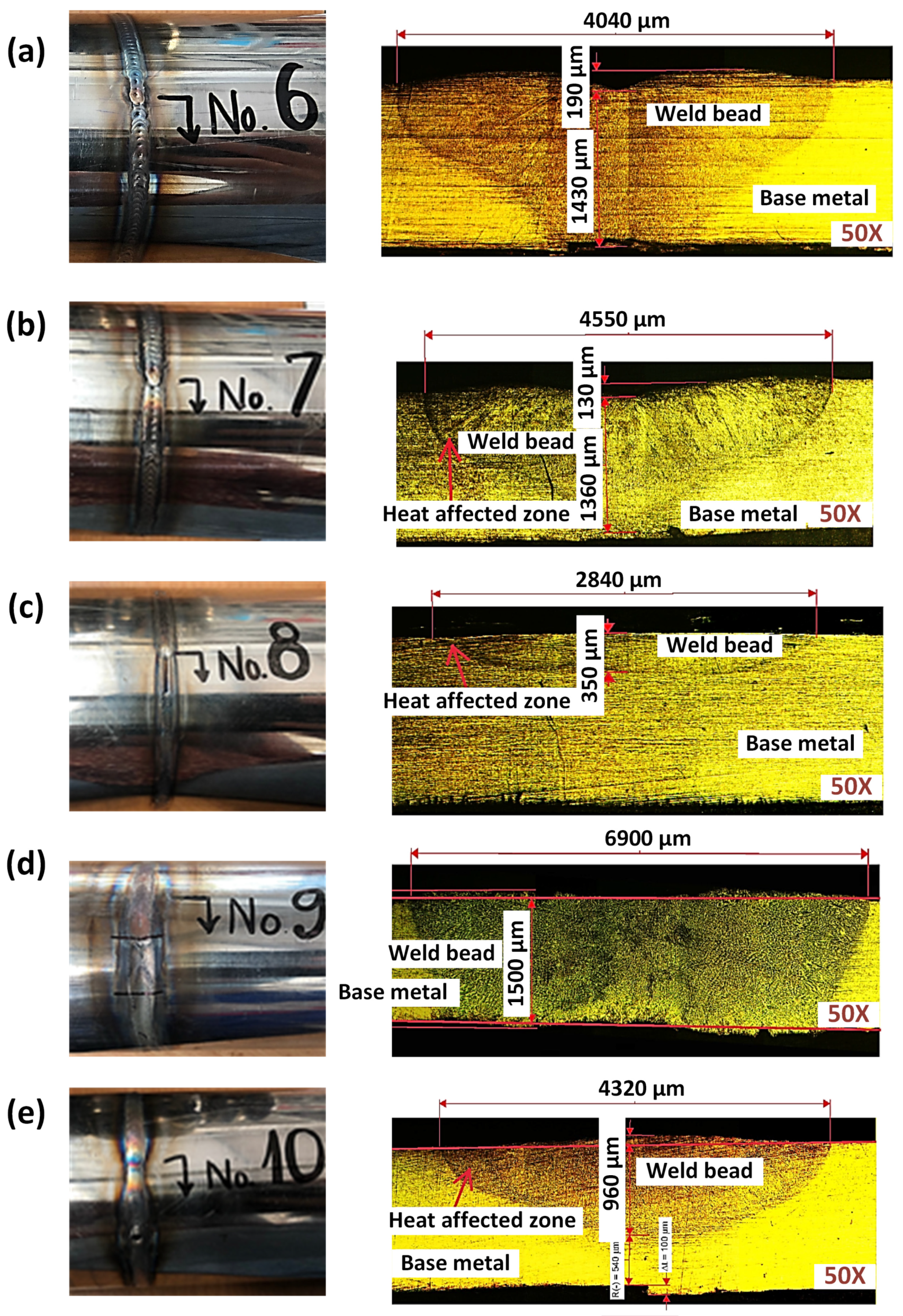
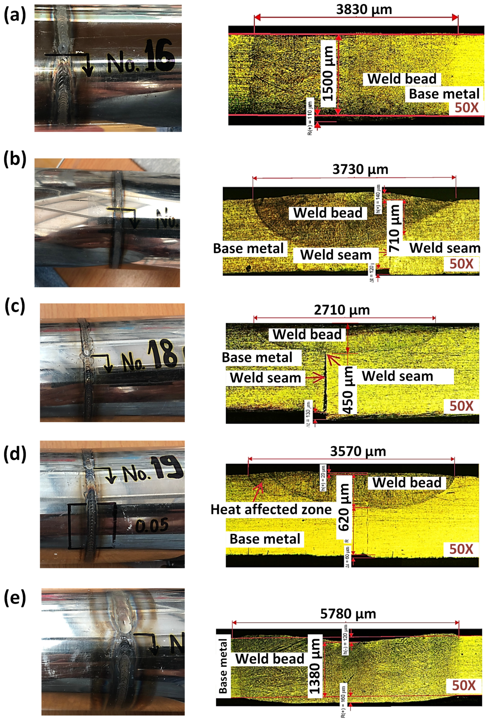
3.1. Geometry, Macrostructure, and Tensile Test

The welded samples are tested via geometry measurement, macrostructure test, and tensile test. Figure 3 presents the geometry, macrostructure, and tensile test results of a typical TIG sample of sample 7. Figure 3a shows that the weld bead is successfully formed and has a good appearance. Moreover, Figure 3b indicates three zones of the welding sample: the welded zone, the heat-affected zone, and the based substrate zone. The macrostructure of the sample presents an austenite matrix phase [21]. The stress–strain diagram of sample 7 is shown in Figure 3c. The UTS value of sample 7 is 597 MPa, which is greater than the original pipe. This sample is classified as a passed case. The results of the other samples are presented in Table 4.
Table 4 shows the weld width, penetration depth, and ultimate tensile strength of the orbital weld SUS 304 samples. In group A, with an electrode angle of 30°, the UTS values are 296 MPa, 334 MPa, 421 MPa, 481 MPa, and 618 MPa, corresponding to samples 1, 2, 3, 4, and 5. Sample 5 only has a good UTS value of 618 MPa, which is higher than the value of the original pipe (500 MPa). Other samples have lower UTS values due to the DOP values being insufficient. Moreover, the presence of the weld seams in samples 1, 2, and 3 also contributes to the reduction of the UTS value compared to the original pipe, as shown in Figure 4. In other words, with the parameters of samples 1, 2, and 3, the pipes are not molten well; as the welding current and the torch height are not enough, the DOP value is not sufficient. Moreover, sample 4 has better DOP than samples 1, 2, and 3, with a DOP value of 950 µm, which is also lower than the standard value of 1350 µm. Furthermore, the weld widths of sample 1 and sample 2 are also not sufficient. Combined with the low DOP values, the UTS values of samples 1 and 2 are relatively low. Sample 3 and sample 4, with better weld width, present higher rates of UTS value. Because the low welding current leads to a reduction in the energy capacity, while the low torch height results in a narrow molten weld bead [18], in summary, the low electrode angle of 30° requires high levels of torch height and welding current to form a good weld bead.
In group B, with an electrode angle of 45°, the UTS values are 500 MPa, 597 MPa, 326 MPa, 629 MPa, and 617 MPa, corresponding to samples 6, 7, 8, 9, and 10. Interestingly, only sample 8 has a failed result in the UTS value, which is only 326 MPa. In sample 8, despite the welding current being high enough, the increased travel speed value of 216 mm/min and the low pulse time of 0.1 s led to a decline in the weld heat input [16]. Moreover, Figure 5 shows that the DOP of sample 8 is only 0.35 mm, which is very low compared to the standard value of 1.35 mm. Furthermore, sample 6 only obtains a UTS value of 500 MPa, which is not higher than that of the original pipe. The reason for this phenomenon is the low torch height of 1 mm of sample 6, which leads to a low value of weld width as the heat could not diffuse further. Samples 7, 9, and 10 have good UTS values. However, sample 10 has a low DOP value of 0.96 mm, which is lower than the required standard of 1.35 mm. In sample 10, because of the high torch height of 2 mm, the DOP value is insufficient as the heat input is scattered in a broad area. In general, samples 7 and 9 passed the quality evaluation.
In group C, with an electrode angle of 60°, the UTS values of samples 11, 12, 13, 14, and 15 are 323 MPa, 403 MPa, 554 MPa, 459 MPa, and 154 MPa. Only sample 13 has a good UTS value of 554 MPa. Sample 13 has good geometry with a high weld width and DOP values, as shown in Figure 6. On the contrary, sample 11, with a groove in the weld bed, leads to a strong reduction in the UTS value, which is only 323 MPa. Furthermore, samples 12, 14, and 15, with low values of weld width and DOP, do not obtain sufficient UTS values. Sample 15, especially, only gains a UTS value of 154, which is very low. The reason could be the high rate of the torch height and the low rate of the pulse time reduced to heat the input concentration; therefore, the weld width and the DOP values are very low compared to other samples in the group [16]. Generally, sample 13 passes the quality evaluation.
In group D, with an electrode angle of 90°, the UTS values of samples 16, 17, 18, 19, and 20 are 582 MPa, 403 MPa, 209 MPa, 240 MPa, and 536 MPa. Sample 16 and sample 20 have good UTS values of 582 MPa and 536 MPa, respectively, due to the high level of DOP, as shown in Figure 7. However, the DOP value of sample 16 is 3.85 mm, which is also not enough. Only sample 20 has a good DOP value of 5.78 mm. Other samples have low DOP values; therefore, the UTS values are lower than those of the original pipe. In particular, the low DOP values of samples 17, 18, and 19 result in a poor geometry of the welded bead, thus reducing the strength of the welded joints. With a torch height of 1.0 mm, the weld width of sample 16 is 3.83 mm, which is lower than sample 20. Because sample 20 has a longer torch height of 2 mm, the weld width could reach 5.78 mm. Finally, the groove in the surface of sample 20 is deeper, leading to a lower UTS value when compared to sample 16. In summary, at an electrode angle of 90° and a torch height of 2 mm, sample 20 passes the quality evaluation.
In group E, with an electrode angle of 120°, the UTS values of samples 21, 22, 23, 24, and 25 are 343 MPa, 53 MPa, 583 MPa, 345 MPa, and 458 MPa. Only sample 23 has good UTS values of 583 MPa. Samples 21, 22, 24, and 25 have low DOP values; therefore, the UTS values are smaller than 500 MPa. Notably, sample 22 has an extremely low DOP, leading to a minor UTS value of 53 MPa due to a big gap between two pipes, as shown in Figure 8. Moreover, the low welding current of sample 22 also leads to a low value of DOP [13]. In addition, sample 21 has a good weld width of 4.88 mm, but the DOP value is only 0.9 mm. Therefore, the UTS value of sample 21 is not sufficient. Generally, sample 23 passes the quality evaluation.
In summary, five samples pass the evaluation of weld width, DOP, and UTS value: samples 5, 7, 9, 13, 20, and 23, as shown in Table 5. Samples 3, 4, and 21 have good weld widths, but the DOP and UTS values fail. The reasons are the long pulse time (200 ms) combined with the high weld speed (180 mm/min); therefore, the distance between the weld pools is too far. The structure of the weld beads lacks continuity, leading to poor DOP and UTS values. The low electrode angle of 30° often results in a good weld width but a poor DOP value as the heat input scatters mostly in the sample surface.
In reverse, samples 6 and 16 achieve good DOP and UTS values, but the weld width is not sufficient. The main reason is the short length of the arc, which is only 1 mm, leading to the concentration of heat in a narrow area. Thus, the DOP value is good, but the weld width is poor. Furthermore, sample 10 passes the UTS evaluation, but the DOP and weld width values are not sufficient. The reason is that the DOP value of sample 10 is mostly close to the 3 t standard, and the groove on the sample surface has a positive value.
When considering the weld root, due to the formation of the weld bead, the full penetration depth could be lower than 1500 µm, which is the thickness of the tube. For example, sample 7 is fully penetrated, but the DOP values are only 1360 µm. This sample is not as good as other passed samples. On the other hand, sample 11 has a negative groove; therefore, despite the weld width and the DOP values being good, the UTS value fails. Moreover, some weld defects appear on the macrostructure of sample 11, thus reducing its tensile strength, as shown in Figure 5. Remarkably, group B with an electrode angle of 45° gains the highest rate of passed samples according to ASME IX in terms of the UTS value, with four passed samples. This phenomenon indicates the advantage of the electrode angle of 45°.

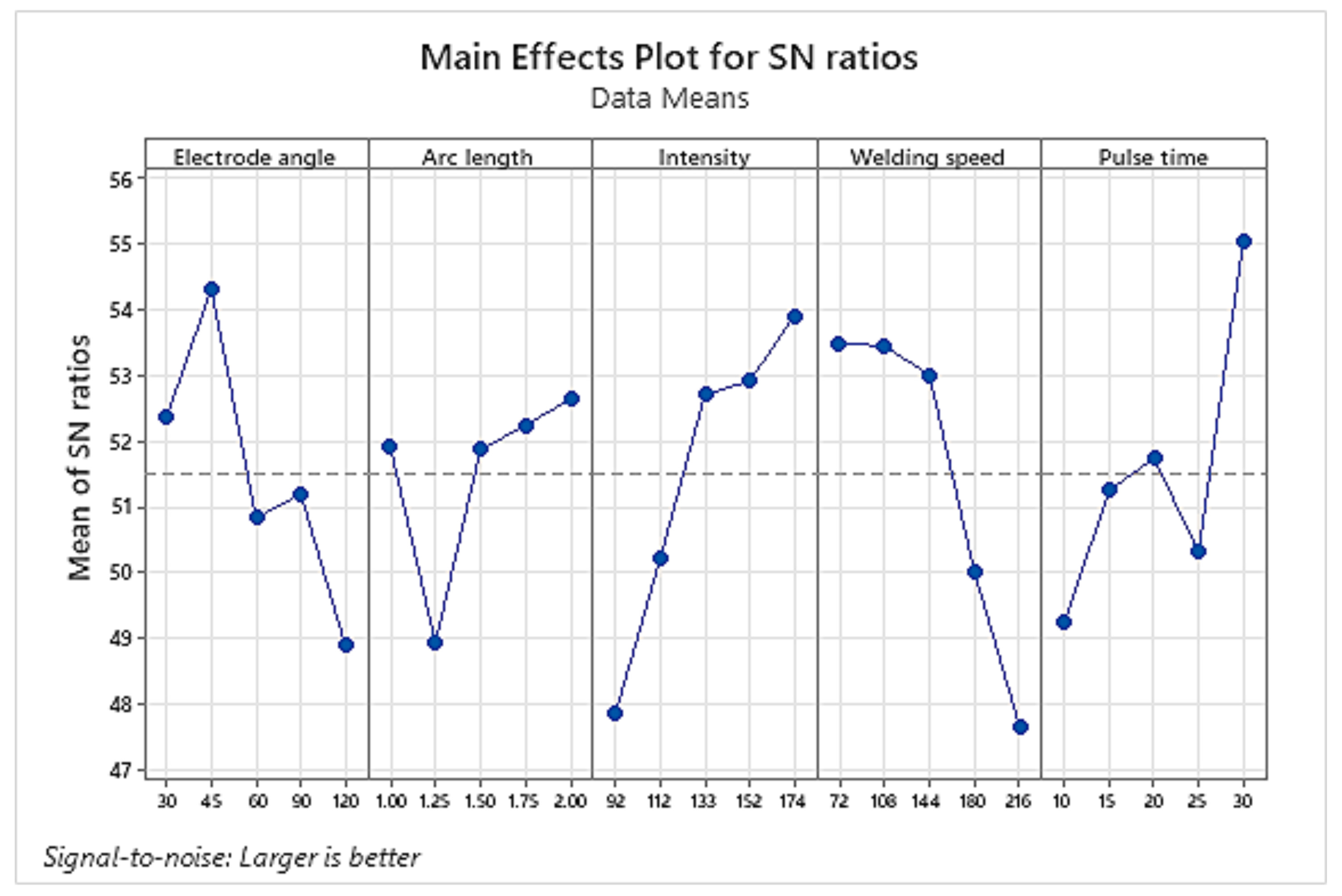
3.2. Taguchi Analyzed for UTS Value

The manufacturing process can be optimized using the Taguchi method [30,31,32]. Additionally, it supports experiments’ design, especially when several variables are taken into account. Minitab 20.3 version software, an L25 orthogonal array, five factors, and five levels are used in the analysis, as shown in Table 1. The response table for signal-to-noise ratios for the UTS value is presented in Table 6. The results show that the welding current has the strongest effect on the UTS value, followed by the welding speed, pulse time, electrode angle, and torch height. As shown in Figure 9, an increase in the welding current in the examined range leads to an increase in the UTS value. Moreover, Figure 9 indicates that the optimal parameters for the UTS value with the “larger is better” option are an electrode angle of 45°, a torch height of 2.0 mm, a welding current of 174 A, a welding speed of 72 mm/min, and a pulse time of 0.3 s. In the surveyed range, it appears to achieve the highest UTS value, as shown in Figure 9, with the highest point at 45° in the “electrode angle” section. Because the electrode angle has a direct impact on the width of the penetration, an electrode angle of 45° will result in a more cylindrical arc due to the decreased arc tension. In the surveyed range, it appears to achieve the highest UTS value, as shown in Figure 9, with the highest point at 45° in the “electrode angle” section. Because the electrode angle has a direct impact on the width of the penetration, an electrode angle of 45° will result in a more cylindrical arc due to the decreased arc tension.

4. Conclusions

In this study, the effects of the welding angle, welding current, travel speed, pulse time, and torch height are examined in relation to the geometry, macrostructure, and mechanical characteristics of TIG orbital welding on an SUS 304 stainless steel pipe. Some important points that could be mentioned are:
-
The electrode angle of 45° achieves a higher rate of good welding joints than the angles of 30°, 60°, 90°, and 120° due to the suitable weld width in orbital welding of a thin SUS 304 stainless steel pipe. Moreover, the electrode angle of 30° has a good weld width but a low DOP value.
-
The welding current and weld speed have a great impact on the distribution of the heat during the TIG welding of the SUS 304 stainless steel pipe. The high welding current could lead to blowholes as the pipe is molten, especially at the end of the welding process when the heat is accumulated.
-
A long torch height of 2 mm results in an unevenness of the weld joints as the arc could be distorted compared to the shorter torch height cases.
-
A pulse time of 0.2 is too long for a low-welding current case because it will form a small weld pool. Therefore, the weld pool solidification process is short, and porosity appears in the weld bead. A pulse time of 0.1 s creates a better weld joint. However, if the welding current is high and the welding speed is low, the pulse time needs to be higher to prevent the negative groove appearance.
-
Taguchi’s results show that welding current has the strongest effect on the UTS value, followed by the welding speed, pulse time, electrode angle, and torch height. The optimal parameters for the UTS value with a larger or a better option are an electrode angle of 45°, a torch height of 2.0 mm, a welding current of 174 A, a welding speed of 72 mm/min, and a pulse time of 0.3 s.

Author Contributions

P.S.M., T.T.D. and T.M.T.U.: conceptualization, funding acquisition; H.D.S.T., T.M.T.U. and V.-T.N.: writing original draft, investigation; P.S.M., T.T.D. and V.-T.N.: analyzing, visualization; T.M.T.U., P.S.M. and H.T.T.L.: project administration; T.T.D., H.T.T.L. and V.-T.N.: investigation; V.T.T.N., H.D.S.T. and V.-T.N.: writing, review, and editing. All authors have read and agreed to the published version of the manuscript.

Funding

This research was funded by HCMC University of Technology and Education.

Institutional Review Board Statement

Not applicable.

Informed Consent Statement

Not applicable.

Data Availability Statement

The data used to support the findings of this study are available from the corresponding author upon request. The data are not publicly available due to the data also forms part of an ongoing study.

Acknowledgments

We acknowledge HCMC University of Technology and Education for their support.

Conflicts of Interest

The authors declare no conflict of interest.

References

  1. Dhanda, K.H.; Badheka, V.J. Effect of activating fluxes on weld bead morphology of P91 steel bead-on-plate welds by flux assisted tungsten inert gas welding process. J. Manuf. Process. 2015, 17, 48–57. [Google Scholar] [CrossRef]
  2. Pandey, C.; Mahapatra, M.M.; Kumar, P.; Saini, N. Dissimilar joining of CSEF steels using autogenous tungsten-inert gas welding and gas tungsten arc welding and their effect on δ-ferrite evolution and mechanical properties. J. Manuf. Process. 2018, 31, 247–259. [Google Scholar] [CrossRef]
  3. Chern, T.S.; Tseng, K.H.; Tsai, H.L. Study of the characteristics of duplex stainless steel activated tungsten inert gas welds. Mater. Des. 2011, 32, 255–263. [Google Scholar] [CrossRef]
  4. Mamvura, T.A.; Paterson, A.E.; Fanucchi, D. The impact of pipe geometry variations on hygiene and success of orbital welding of brewing industry equipment. J. Inst. Brew. 2017, 123, 81–97. [Google Scholar] [CrossRef]
  5. Nagy, V.; Mnerie, G.V.; Safta, V.I.; Mnerie, D. Critical analysis of some practices of joining stainless steel pipes used in the food industry from the perspective of hygienic welding principles. In Defect and Diffusion Forum; Trans Tech Publications Ltd.: Stafa-Zurich, Switzerland, 2022; Volume 416, pp. 145–150. [Google Scholar]
  6. Krustev, A.; Alexandrov, B.; Kovacich, J. Modified GTAW Orbital Tube-to-Tubesheet Welding Technique, and the Effect of a Copper Weld Retainer During Welding of Alloy 825. In Pressure Vessels and Piping Conference; American Society of Mechanical Engineers: New York, NY, USA, 2017; Volume 57991, p. V06AT06A021. [Google Scholar]
  7. Jackson, R.B.; Vengosh, A.; Carey, J.W.; Davies, R.J.; Darrah, T.H.; O’sullivan, F.; Pétron, G. The environmental costs and benefits of fracking. Annu. Rev. Environ. Resour. 2014, 39, 327–362. [Google Scholar] [CrossRef]
  8. Zabbey, N.; Olsson, G. Conflicts–oil exploration and water. Glob. Chall. 2017, 1, 1600015. [Google Scholar] [CrossRef]
  9. Razvarz, S.; Jafari, R.; Gegov, A. Flow modelling and control in pipeline systems. Stud. Syst. Decis. Control 2021, 321, 25–57. [Google Scholar]
  10. Ngo, G.V. Automated orbital welding of carbon and low-alloy steels pipelines with small diameter. In Materials Science Forum; Trans Tech Publications Ltd.: Stafa-Zurich, Switzerland, 2020; Volume 989, pp. 766–771. [Google Scholar]
  11. Lima, E.J.; Fortunato Torres, G.C.; Felizardo, I.; Ramalho Filho, F.A.; Bracarense, A.Q. Development of a robot for orbital welding. Ind. Robot Int. J. 2005, 32, 321–325. [Google Scholar] [CrossRef]
  12. Figueirôa, D.W.; Pigozzo, I.O.; Silva, R.H.G.E.; Santos, T.F.D.A.; Urtiga Filho, S.L. Influence of welding position and parameters in orbital tig welding applied to low-carbon steel pipes. Weld. Int. 2017, 31, 583–590. [Google Scholar] [CrossRef]
  13. Li, X.R.; Shao, Z.; Zhang, Y.M.; Kvidahl, L. Monitoring and control of penetration in GTAW and pipe welding. Weld. J. 2013, 92, 190–196. [Google Scholar]
  14. Silva, R.H.G.E.; Schwedersky, M.B.; da Rosa, Á.F. Evaluation of toptig technology applied to robotic orbital welding of 304L pipes. Int. J. Press. Vessel. Pip. 2020, 188, 104229. [Google Scholar] [CrossRef]
  15. Górka, J.; Przybyła, M.; Szmul, M.; Chudzio, A.; Ładak, D. Orbital TIG welding of titanium tubes with perforated bottom made of titanium-clad steel. Adv. Mater. Sci. 2019, 19, 55–64. [Google Scholar] [CrossRef]
  16. Lothongkum, G.; Viyanit, E.; Bhandhubanyong, P. Study on the effects of pulsed TIG welding parameters on delta-ferrite content, shape factor and bead quality in orbital welding of AISI 316L stainless steel plate. J. Mater. Process. Technol. 2001, 110, 233–238. [Google Scholar] [CrossRef]
  17. Riffel, K.C.; Dalpiaz, G.; Marques, C.; Schwedersky, M.B. Keyhole GTAW with dynamic wire feeding applied to orbital welding of 304L SS pipes. Soldag. Inspeção 2019, 24, e2418. [Google Scholar] [CrossRef]
  18. Kumar, A.; Jain, V.; Gupta, D.; Agrawal, M. Experimental Investigation of SS-304 by using Orbital Welding with A-TIG Process. Indian J. Sci. Technol. 2017, 10, 31. [Google Scholar] [CrossRef]
  19. Niagaj, J.; Jędrusiak, A. The Effect of Shielding Gas Composition and Orbital TIG Welding Parameters on the Dimensions and Quality of Austenitic Stainless Steel Pipe Girth Welds. Biul. Inst. Spaw. W Gliwicach 2015, 59, 5–12. [Google Scholar]
  20. Pradhan, S.K. Finite element simulation and optimization of orbital welding process parameters. Mater. Today Proc. 2018, 5, 12886–12900. [Google Scholar]
  21. Engelhard, G.; Habip, L.M.; Pellkofer, D.; Schmidt, J.; Weber, J. Optimization of residual welding stresses in austenitic steel piping: Prooftesting and numerical simulation of welding and postwelding processes. Nucl. Eng. Des. 2000, 198, 141–151. [Google Scholar] [CrossRef]
  22. Vänskä, M.; Purtonen, T.; Salminen, A. Orbital cutting and welding of stainless steel tubes with a fiber laser. In International Laser Safety Conference; AIP Publishing: New York, NY, USA, 2011; pp. 612–620. [Google Scholar]
  23. Baskoro, A.S.; Kiswanto, G.; Widyianto, A. Optimization of PC-GTAW Orbital Welding Parameters of AISI 304L Stainless Steel Pipe Using ANOVA and Taguchi Method. In IOP Conference Series: Materials Science and Engineering; IOP Publishing: Bristol, UK, 2020; Volume 727, No. 1; p. 012007. [Google Scholar]
  24. Widyianto, A.; Baskoro, A.S.; Kiswanto, G.; Ganeswara, M.F.G. Effect of welding sequence and welding current on distortion, mechanical properties and metallurgical observations of orbital pipe welding on SS 316L. East.-Eur. J. Enterp. Technol. 2021, 2, 110. [Google Scholar] [CrossRef]
  25. Singh, N.K.; Pradhan, S.K. Experimental and numerical investigations of pipe orbital welding process. Mater. Today Proc. 2020, 27, 2964–2969. [Google Scholar] [CrossRef]
  26. Elmer, J.W.; Gibbs, G. The effect of sulfur content on weld penetration in austenitic stainless steel orbital tube welds. Weld. J. 2022, 101, 1045368. [Google Scholar]
  27. Dak, G.; Pandey, C. Experimental investigation on microstructure, mechanical properties, and residual stresses of dissimilar welded joint of martensitic P92 and AISI 304L austenitic stainless steel. Int. J. Press. Vessel. Pip. 2021, 194, 104536. [Google Scholar] [CrossRef]
  28. Kagay, B.; San Marchi, C.; Pericoli, V.; Foulk, J., III. Hydrogen effects on fatigue life of welded austenitic stainless steels evaluated with hole-drilled tubular specimens. In Pressure Vessels and Piping Conference; American Society of Mechanical Engineers: New York, NY, USA, 2020; Volume 83860, p. V006T06A090. [Google Scholar]
  29. Aliha, M.R.M.; Ghoreishi, S.M.N.; Imani, D.M.; Fotoohi, Y.; Berto, F. Mechanical and fracture properties of aluminium cylinders manufactured by orbital friction stir welding. Fatigue Fract. Eng. Mater. Struct. 2020, 43, 1514–1528. [Google Scholar] [CrossRef]
  30. Rafferty, J.G. Optimisation of Heat Pressure Welding of Steel Wire in Flexible Riser Manufacture, Applying Taguchi Design-of-Experiment Approaches. In International Conference on Offshore Mechanics and Arctic Engineering; American Society of Mechanical Engineers: New York, NY, USA, 2012; Volume 44939, pp. 177–185. [Google Scholar]
  31. Karthikeyan, M.; Naikan, V.N.; Narayan, R.; Sudhakar, D.P. Orbital TIG welding process parameter optimization using design of experiment for satellite application. Int. J. Perform. Eng. 2016, 12, 155. [Google Scholar]
  32. Mosavvar, A.; Azdast, T.; Moradian, M.; Hasanzadeh, R. Tensile properties of friction stir welding of thermoplastic pipes based on a novel designed mechanism. Weld. World 2019, 63, 691–699. [Google Scholar] [CrossRef]
Figure 1. Sample shape according to ASME IX standard and sample preparation: (a) Positions for selecting tensile test sample according to ASME IX standard, (b) tensile test sample shape according to ASME IX standards, (c) machined tensile samples, and (d) macrostructure test samples.
Metals 14 00005 g001
Figure 2. Experimental equipment: (a) Welding machine JASIC TIG 250A, (b) welding control panel system, (c) automatic welding fixture, (d) electrode grinding machine with angled fixture, (e) metallurgical microscope Oxion OX.2153-PLM EUROMEX, and (f) SANS model CHT4106 tensile test machine.
Metals 14 00005 g002
Figure 3. Geometry, macrostructure, and stress–strain diagram of sample 7: (a) weld width, (b) macrostructure, and (c) stress–strain diagram.
Metals 14 00005 g003
Figure 4. Geometry and macrostructure of samples in group A: (a) sample 1, (b) sample 2, (c) sample 3, (d) sample 4, and (e) sample 5.
Metals 14 00005 g004
Figure 5. Geometry and macrostructure of samples in group B: (a) sample 6, (b) sample 7, (c) sample 8, (d) sample 9, and (e) sample 10.
Metals 14 00005 g005
Figure 6. Geometry and macrostructure of samples in group C: (a) sample 11, (b) sample 12, (c) sample 13, (d) sample 14, and (e) sample 15.
Metals 14 00005 g006
Figure 7. Geometry and macrostructure of samples in group D: (a) sample 16, (b) sample 17, (c) sample 18, (d) sample 19, and (e) sample 20.
Metals 14 00005 g007
Figure 8. Geometry and macrostructure of samples in group E: (a) sample 21, (b) sample 22, (c) sample 23, (d) sample 24, and (e) sample 25.
Metals 14 00005 g008
Figure 9. Main effects plot for SN ratios (larger is better).
Metals 14 00005 g009
Table 1. Chemical composition of SUS 304 steel pipes.
CSiMnPSNCrNi
0.07% max1% max2% max0.045% max0.015% max0.11% max17.5–19.5%8–10.5%
Table 2. Welding parameters of the TIG orbital welding process for 25 samples of SUS 304 steel pipes.
GroupNo.Electrode Angle (°)Torch Height (mm)Welding Current (A)Pulse Time (ms)Welding Speed (mm × min−1)
A13019210072
2301.25112150108
3301.5133200144
4301.75152250180
5302174300216
B6451112250144
7451.25133300180
8451.5152100216
9451.7517415072
1045292200108
C11601133150216
12601.2515220072
13601.5174250108
14601.7592300144
15602112100180
D16901152300108
17901.25174100144
18901.592150180
19901.75112200216
2090213325072
E211201174200180
221201.2592250216
231201.511230072
241201.75133100108
251202152150144
Table 3. Evaluation standards of weld width according to ASME IX standard and DOP according to ASME BPE standard.
Sample Thickness—t (mm)Weld Width (mm)DOP (mm)
<0.256 t0.9 t
≥0.25 and <0.505 t
≥0.50 and <1.004 t
≥1.00 and <1.753 t
≥1.75 and <2.542.50 t
≥2.54 and <3.002.25 t
≥3.00 and <4.002 t
≥4.001.80 t
Table 4. Weld width, penetration depth, and ultimate tensile strength of the orbital weld SUS 304 samples.
GroupNo.Weld Width (mm)DOP (mm)UTS (MPa)
A12.720.60296
23.630.74334
34.670.70421
44.990.95481
55.281.50618
B64.041.43500
74.551.36597
82.840.35326
96.901.50629
104.320.96617
C115.541.40323
123.770.53403
136.721.50554
143.610.8459
152.220.25154
D163.831.50582
173.730.71403
182.710.45209
193.570.62240
205.781.38536
E214.880.90343
222.410.2353
234.791.50583
243.440.58345
253.890.64458
Table 5. Summary of 6 passed samples among 25 samples of the orbital weld SUS 304 process.
GroupNo.Electrode Angle (°)Torch Height (mm)Welding Current (A)Welding Speed (mm/min)Pulse Time (ms)Results
Weld Width,
≥3 t
DOP,
≥0.9 t
UTS,
≥500 MPa
A53021742163005.281.5618
B7451.251331803004.551.36597
9451.75174721506.901.5629
C13601.51741082506.721.5554
D20902133722505.781.5536
E231201.5112723004.791.5583
Table 6. Response Table for Signal to Noise Ratios for UTS value (larger is better).
LevelElectrode AngleTorch HeightWelding CurrentWelding SpeedPulse Time
152.3751.9247.8753.4849.26
254.3148.9450.2253.4451.25
350.8351.8752.7153.0051.74
451.2052.2452.9150.0050.31
548.9052.6453.8947.6755.04
Delta5.413.706.025.815.78
Rank45123
Disclaimer/Publisher’s Note: The statements, opinions and data contained in all publications are solely those of the individual author(s) and contributor(s) and not of MDPI and/or the editor(s). MDPI and/or the editor(s) disclaim responsibility for any injury to people or property resulting from any ideas, methods, instructions or products referred to in the content.

