Article

Numerical Simulation on Crack–Inclusion Interaction for Rib-to-Deck Welded Joints in Orthotropic Steel Deck

1
College of Civil Engineering, Hunan University of Technology, Zhuzhou 412007, China
2
Intelligent Control of Safety and Risk for Existing Engineering Structures, Key Laboratory of Hunan Province, Zhuzhou 412007, China
*
Author to whom correspondence should be addressed.
Metals 2023, 13(8), 1402; https://doi.org/10.3390/met13081402
Submission received: 9 July 2023 / Revised: 31 July 2023 / Accepted: 3 August 2023 / Published: 5 August 2023

Abstract

:
Weld defects such as porosity, inclusion, burn-through, and lack of penetration are difficult to detect and control effectively in an orthotropic steel deck (OSD), which will be a fatigue crack initiation site and lead to several fatigue cracking. The crack growth behavior in defective welded joints is different from that of defect-free joints. This study investigates crack–inclusion interaction for rib-to-deck welded joints in OSDs based on numerical simulation and linear elastic fracture mechanics (LEFM). A refined finite element model of a half U-rib with cracks and inclusions was established by using the FRANC3D-ABAQUS interactive technology. The full processes of the crack–inclusion interaction from approaching and penetrating were accurately simulated. Critical parameters, including the stress intensity factor (SIF), the shape factor, the growth rate, and the growth direction were analyzed. The stiff and soft inclusions amplify and shield the SIF of cracks when the crack grows to the local area of inclusions. During the entire process of crack growth, the soft and stiff inclusion accelerate and inhibit the crack growth, respectively. The stiff inclusion will lead to asymmetric growth of the crack shape, where the portion of the crack away from the inclusions has a higher growth rate. The soft and stiff inclusions will attract and repel the direction of crack growth at the proximal point, respectively.

1. Introduction

Orthotropic steel decks (OSDs) have been widely applied to long-span bridges due to the advantage of lightweight and high load-carrying capacity. However, fatigue cracking is usually detected from the welded joints of a large number of in-service long-span bridges [1,2,3]. Most of the fatigue cracks of steel structures initiate from the weld seam. Stress concentration and high residual stress caused by weld defects are the key internal reason for fatigue cracking [4,5,6]. While optimization of welding parameters can help reduce weld defects [7,8] and automatic welding technology can improve the welding quality and efficiency of the U-shaped rib unit [9,10], it is important to note that welding defects cannot be completely eliminated. Furthermore, the heavy traffic load can accelerate the cracking of weld defects. The influence of weld defects on the fatigue performance of OSDs deserves investigation.
Significant research progresses have been made on the fatigue cracking of typical welded joints in OSDs. In order to evaluate fatigue reliability, the cumulative damage theory has been widely applied [6,11], and the mechanical indexes have experienced the development history of the nominal stress, the notch stress, the hot spot stress, and the strain energy density. However, due to the inability to consider the crack growth paths, the method is limited in the field of structural safety assessment of weld defects. The fatigue reliability assessment method based on the linear elastic fracture mechanics (LEFM) theory is commonly used in existing damaged bridge structures, which involves the distribution characteristics of random variables in the Paris formula [12,13]. For the development of structural details, Da et al. [1] proposed two novel structure details including rib-to-deck (RTD) and rib-to-floorbeam welded joints for a high fatigue resistance of OSDs. The fatigue performance of the RTD double-side welded joints was demonstrated to be superior compared with the RTD welded joints [14,15]. Luo et al. [2] investigated the fatigue performance of an innovative RTD welded joint linking the longitudinal U-rib and deck plate of OSDs. As for the repair and reinforcement in OSDs, ultra-high-performance concrete has been extensively used in welded connections to improve structural characteristics and extend fatigue lives [16,17]. The high-strength bolts for stop-hole were proposed by Fang et al. [18] to alleviate fatigue damage accumulation at the crack tip to arrest continuous growth.
It is essential to have a comprehensive understanding of the dynamic evolution characteristics of cracks. Extensive research effects have been conducted on dynamic growth analysis of fatigue cracks based on various theoretical methods, including LEFM theory, extended finite element (XFEM) [19,20], and fatigue test [14,21]. The critical point of the LEFM method is the crack tip stress intensity factors (SIFs). It is common for scholars to assume that weld defects take the form of planar semi-elliptical cracks. Additionally, the Paris formula is used to calculate the number of cycles required for the initial crack to reach a critical length. In the context of complex crack growth problems, the XFEM and stochastic finite element methods are very popular in this regard. With the development of computer technology, solutions such as ABQUS-FRANC3D [15] (F-A) interactive technologies and 3D fracture analysis approach [22,23] are developing fast. Scanning electron microscopy (SEM) [24] can be used to observe the microscopic morphology of cracks at the fracture of fatigue specimens, which greatly promotes the research on the mechanism of crack growth through fatigue tests. In the study of random fatigue crack growth, scholars assume that crack growth obeys a certain probability distribution type. Lu et al. [25] investigated the evaluated the random propagation paths of the crack under stochastic traffic loads. They found that the transverse distribution of the wheel tracks had a significant influence on the torsion angle. Wang et al. [26] proposed the use of a lognormal function to fit the distribution of the life until a crack grows to half the thickness of the deck plate, based on the weigh-in-motion data on an OSD for one year. Based on the Markov chain, Guo et al. [27] predicted the growth curve of the fatigue crack depth of U-shaped rib members as a function of service time. The above studies generally simplify weld defects as planar semi-elliptical cracks, while the influence of defect types on fatigue fracture of welds is ignored.
Recently, the fatigue cracks growth behavior of welded joints with multiple defects in OSDs have caught the attention of researchers and engineers. Wang et al. [28] proposed a homogenization coefficient to consider the effect of random defects on crack growth. They discovered that the initial crack size plays a crucial role in determining the initiation life of macro-cracks. Nevertheless, it is important to note that other weld defects and traffic flow can introduce certain levels of uncertainties. For the interaction between crack-like weld defects, Cui et al. [14] found that multi-crack propagation and coalescence phenomenon significantly accelerate the fatigue failure of double-side welded RTD joint. Liu et al. [19] revealed and verified the whole process of in-plan double-crack propagation in RTD weld toe of OSDs, and concluded that the fatigue life of the two in-plane cracks decreases with the increasing crack spacing and crack shape ratio. The aforementioned research demonstrates that the crack growth characteristics of multi-cracks and single cracks exhibit notable distinctions. The multi-defects in welded joints in OSDs are worthy of further study. However, limited studies involve the interaction action between the other welding defects and cracks. Further investigation of fatigue crack propagation behavior at the weld defects in OSDs is necessary.
In the present study, numerical simulation was conducted to investigate the crack–inclusion interaction and the fatigue growth behavior for RTD welded joints in OSDs based on LEFM. A refined finite element model of a half U-rib with cracks and inclusions was established by using the FRANC3D-ABAQUS interactive technology. The full processes of the crack–inclusion interaction from approaching and penetrating were accurately simulated. Critical parameters, such as the SIF, the shape factor, the growth rate, and the growth direction were analyzed.

2. Theoretical Bases and Numerical Verification

2.1. Fatigue Crack Growth Theory Based on Fracture Mechanics

2.1.1. SIFs Computation Based on the M-Integra

The path-independent integral theory in fracture mechanics is a useful tool for assessing the strength and failure of crack bodies. This theory includes J-integral, M-integral, and L-integral, where M-integral is particularly suitable for evaluating the damage of materials with complex defects or multiple cracks. Yan et al. [29] proposed the M-integral from J-Integral, written as
J = Γ ( σ i j u i x 1 W δ 1 j ) q x j d s
where Γ is the integral path around the crack tip; σij is the stress tensor; μi is the displacement vector; x1 is the position vector of the integration point; the strain energy density W is defined as W = 1 2 σ i j ε i j , εij is the strain tensor; δ1j is the crack tip opening displacement; q is a function that is 1 at the crack tip and 0 at the boundary of the integration domain, respectively; ds is a small increment along the integration path Γ .
For linear analysis, the filed variables can be obtained by superimposing the actual field with the auxiliary field [29], which is defined as
σ i j = σ i j ( 1 ) + σ i j ( 2 ) ε i j = ε i j ( 1 ) + ε i j ( 2 ) μ i j = μ i j ( 1 ) + μ i j ( 2 )
The J-integral after superposition can be expressed as
J = J ( 1 ) + J ( 2 ) + M ( 1 , 2 )
where
M ( 1 , 2 ) = r ( σ i j ( 1 ) u i ( 2 ) x 1 + σ i j ( 2 ) u i ( 1 ) x 1 W ( 1 , 2 ) δ 1 j ) q x j d s / A q
where M(1,2) is the interaction integral of the auxiliary field and the actual field, i.e., M-integral; A q = L q t d s , qt is the crack front function value, and W(1,2) is the interaction strain energy density, which is defined as
W ( 1 , 2 ) = σ i j ( 1 ) ε i j ( 2 ) = σ i j ( 2 ) ε i j ( 1 ) .
In the small yield state, the J-integral is equal to the energy release rate G [30].
G = J = 1 υ 2 E K 2 + 1 υ 2 E K 2 + 1 υ 2 E K 2
where E is elastic modulus and υ is Poisson’s ratio; K i = K i ( 1 ) + K i ( 2 ) .
The relationship between the M-integral and the SIF K can be written as
M ( 1 , 2 ) = 2 × [ 1 ν 2 E K I ( 1 ) K I ( 2 ) + 1 ν 2 E K I I ( 1 ) K I I ( 2 ) + 1 + ν 2 E K I I I ( 1 ) K I I I ( 2 ) ] .
In finite element analysis (FEA), the SIFs of different types of fatigue cracks can be solved using the simultaneous Equations (4) and (7).

2.1.2. Crack Growth Model

The criterion of fatigue crack growth is the key problem in fatigue cracking analysis. The Paris law model [31] for fatigue crack propagation can be utilized as a connection between the SIF and the crack growth rate, which is written as
d a d N = C ( Δ K e q ) m       K C > Δ K e q > Δ K th
where N represents the number of cycles; C and m are constants associated with material; Δ K e q represents the equivalent SIF range, Δ K e q = K e q , max max ( K e q , min , 0 ) , K e q = K 2 + K 2 + K 2 1 υ ; Δ K th represents the fatigue SIF threshold, which indicates that crack does not propagate when Δ K e q < Δ K th . KC represents the fracture toughness, which indicates that the crack will grow rapidly when Δ K e q > K C .
The fatigue life of the crack based on the Paris law can be expressed as
N = a 0 a f d a C ( Δ K e q ) m
where N represents the number of load cycles, where the fatigue crack undergoes from its initial dimension a0 to the critical dimension af.

2.2. Numerical Verification of FRANC3D-ABAQUS Interactive Technology

The software package FRANC3D (FRANC3D-V8.2.2.2, Fracture Analysis Consultants, lnc., New York, NY, USA) can handle complex structural shapes, load conditions, and crack forms. Unlike other finite elements, FRANC3D uses adaptive mesh re-division technology to ensure a high-quality mesh around the crack tip. The fatigue test results also confirmed the effectiveness and accuracy of FRANC3D in simulating crack growth [32,33,34]. In this study, the F-A technology is introduced to analyze crack structures with inclusions.
To evaluate the accuracy and feasibility of the F-A method, a finite wide plate model was established by using ABAQUS (ABAQUS-2021, Groupe Dassult, Paris, France). Semi-elliptical cracks with varying aspect ratios (a/c) were introduced by FRANC3D, as shown in Figure 1.
The SIFs obtained by the F-A method were compared with the theoretical values in the Raju-Newman handbook [35], and the results are presented in Table 1. It is observed that the finite element calculations are in good agreement with the theoretical values, where the relative error is less than 3.0%. This demonstrates the accuracy and feasibility of the F-A method in calculating SIFs for three-dimensional fracture problems.

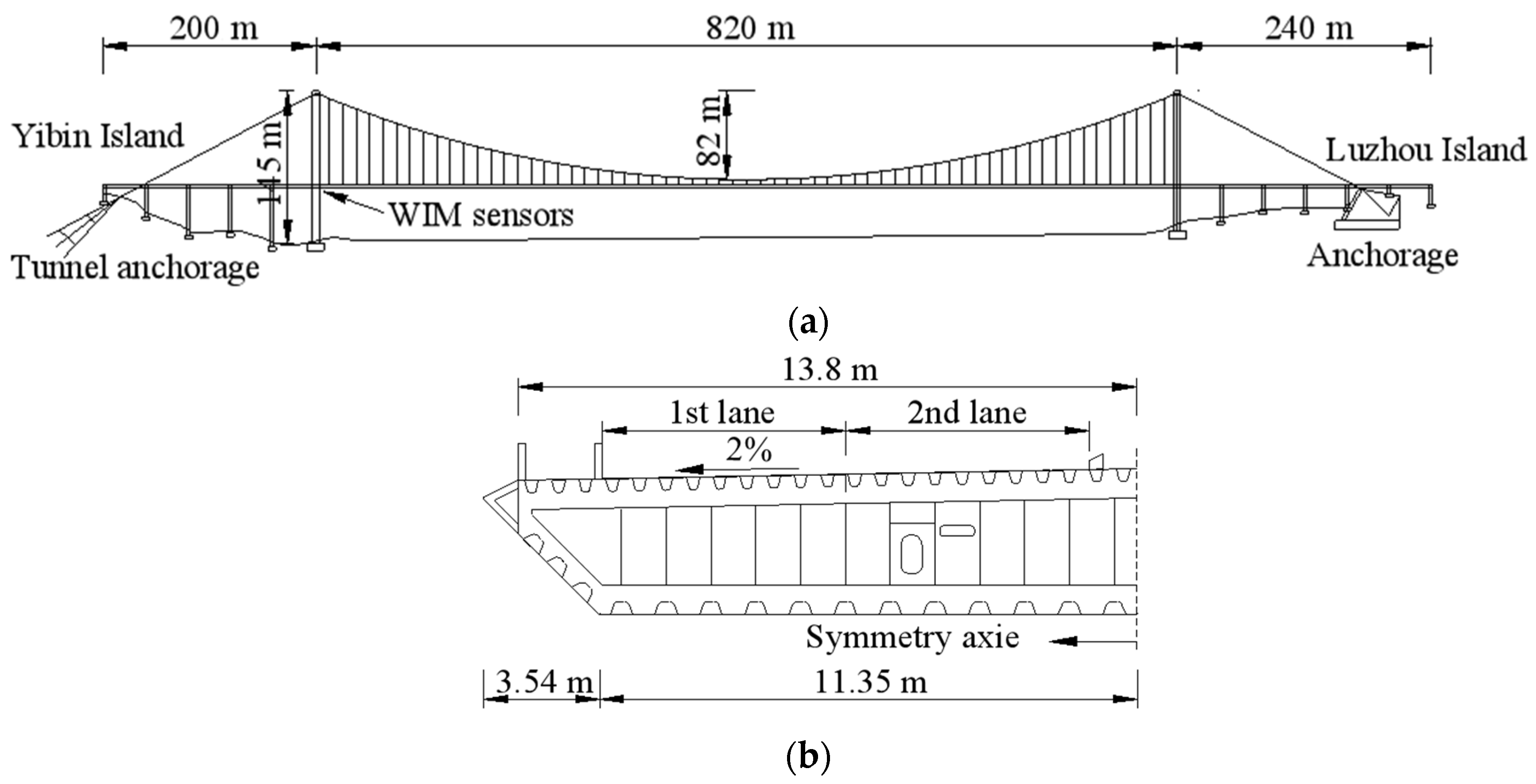
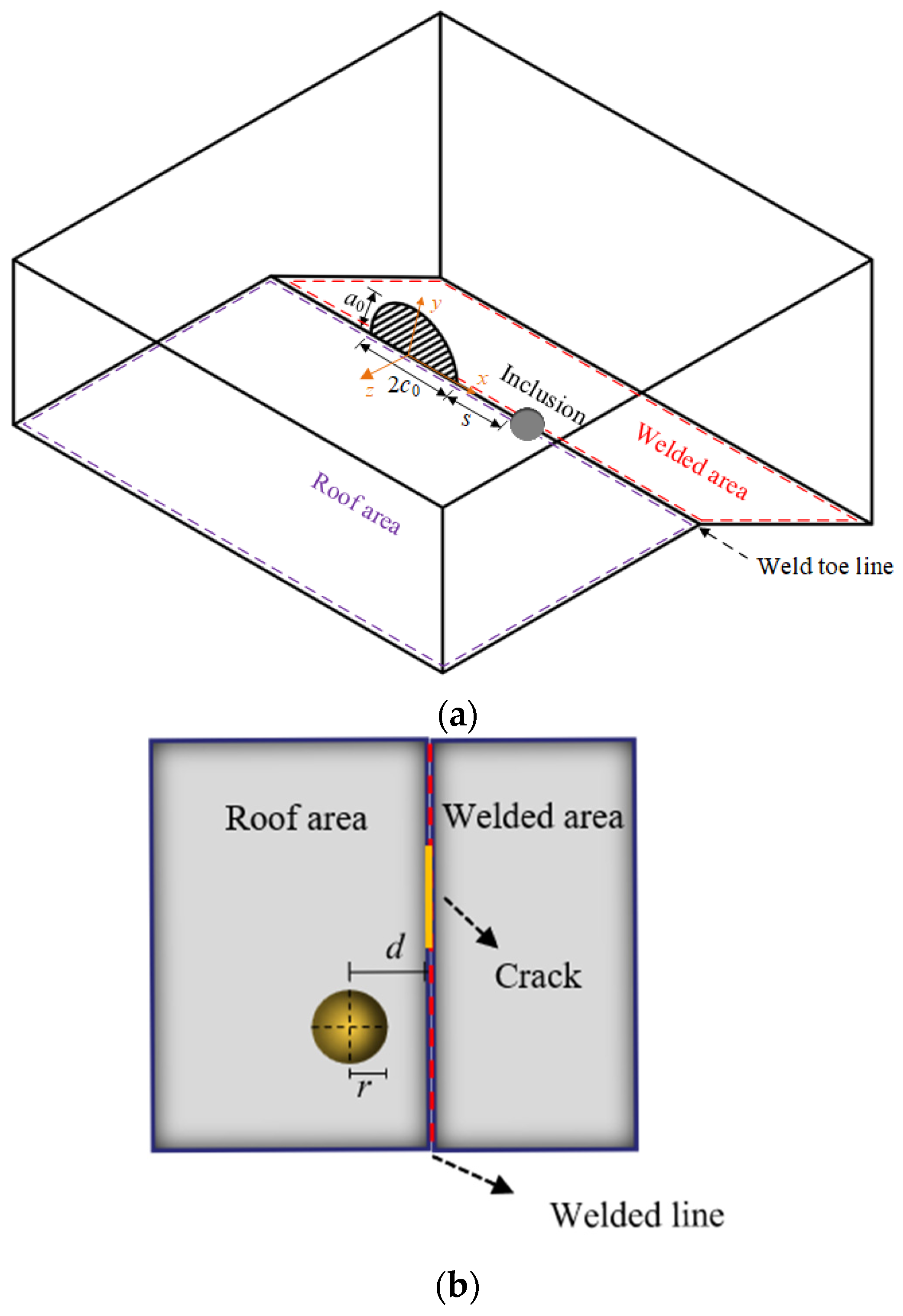
3. Numerical Simulation Description

An OSD of a suspension bridge with a main span of 820 m [15] was chosen as the engineering prototype for the purpose of simulating the fatigue crack growth characteristics in RTD welds. The dimension parameters of the suspension bridge and RTD are illustrated in Figure 2 and Figure 3a, respectively. The thickness of the deck plate and U-rib are 16 mm and 8 mm, respectively. The upper opening width and height of the U-rib are 300 mm and 280 mm, respectively. The weld penetration rate is 80% for the RTD welding seam. Figure 3b illustrates the typical cracks at welded joints (a joint form of groove welding). The two main types of cracks are the toe-deck crack and the root-deck crack, which initiate from the weld toe and the weld root, respectively. The typical crack will propagate through the deck. This study will focus on the growth characteristics of the toe-deck crack.
The process for evaluating growth characteristics of crack interaction with inclusions in RTD welded joints is shown in Figure 4. Initially, a half U-rib model was established by ABAQUS, with an inclusion inserted at the weld toe. Subsequently, the half U-rib model with the inclusion was imported into FRANC3D to generate a local solid model. An initial fatigue crack was inserted near the inclusion on the weld toe line for subsequent analysis.
In the model, a combination of the C3D20R hexahedral element and the C3D10 tetrahedral element was used for mesh hybrid division. The non-weld area was divided using the 10 mm hexahedron, while a denser grid of 2 mm was set in the transition section at the weld joint. For the local area containing particle inclusions, a tetrahedral mesh with a 0.5 mm grid was adopted. For the weld area of concern, a 1 mm grid was adopted. Q345qD steel is used in the U-rib and deck plate in the finite element model. The base material has an elasticity modulus of E0 = 206 GPa and Poisson’s ratio υ = 0.3. According to the principle of equal strength in steel structure design [36], the seam material is assumed to be the same as the base material. The loading area measures 100 mm × 300 mm, and the stress ratio is 0.1. In the structural analysis, symmetric constraints (Ux = Ry = Rz = 0) were applied at the y-z plane of the deck and U-rib. Additionally, vertical constraints (Uy = 0) were applied on the left deck, and constraints (Uz = 0) were applied on the deck (z = 0) to simulate the actual boundary conditions.
As observed from Figure 4, the initial aspect ratio of the crack was assumed to be 0.5 (with a0 = 0.5 mm, c0 = 1 mm), in accordance with the ⅠⅠW [37] recommendation. The crack size limit in the depth direction was assumed half the plate thickness. The inclusion was simulated by spheres with a radius of 1.5 mm. Further research on stress and the propagation of cracks will be conducted based on the FE model.

4. Results and Discussion

4.1. Crack–Inclusion Interaction Analysis

4.1.1. Crack–Inclusion Stress Distribution

The impact of inclusions on stress distribution around cracks deserves in-depth investigation. It is important to consider the elasticity modulus of different types of inclusions. Sulfide inclusions were categorized as soft inclusions with lower elasticity modulus, whereas oxide inclusions such as MgO and Al2O3 are categorized as stiff inclusions with higher elasticity modulus [38]. To simplify the analysis, the elasticity modulus of soft and stiff inclusions E1 are assumed to be 0.25E0 and 4E0, respectively. As shown in Figure 5a, an inclusion was inserted near the weld toe line to discuss the stress distribution around the crack. The variable d shown in Figure 5b represents the relative position of the inclusion to the crack. The case where the crack passes along the center of the inclusion, i.e., d = 0, is discussed first. Figure 6 presents the stress distribution of cracks in two scenarios, without inclusion and with inclusions. The inclusions are differentiated by their elasticity modulus.
The numerical results of the simulation indicate that the presence of particle inclusions has a significant impact on the stress state in the vicinity. The stress field of the crack is uniformly distributed along the center of the crack in a homogeneous material, as can be observed from Figure 6a. The phenomenon of asymmetry in stress fields around cracks caused by inclusions is directly linked to the elasticity modulus of inclusions. Figure 6b,c indicates that stress concentration primarily occurs inside the stiff inclusion, resulting in higher internal stress as compared to the basic material region. In the case of soft inclusion, the stress value inside the inclusion is not significant, but stress concentration occurs in the region close to the crack. The findings suggest that as the elasticity modulus of the inclusions increases, the stress of the matrix material near the crack initially surpasses that of the inclusions and then decreases below it. In the following section, we will explore the crack growth characteristics in different stress fields.

4.1.2. Crack SIFs Considering Crack–Inclusion

Researchers [39] found that the primary cause of fatigue failure at key welded connections of OSDs was the mode I crack. Therefore, the planar crack growth characteristics are first explored in the section. The stress state of different paths is important in understanding the different stages of crack growth. Figure 7 shows the variations in SIFs of the initial crack at different paths within homogeneous material. Due to software limitations, the SIFs on the 0 and the 1 growth paths may be distorted. Therefore, the SIFs on the 0.1 and 0.9 paths are primarily analyzed to approximately represent the SIF value at the tip of the major axis of the crack.
It can be observed from Figure 7 that the SIFs at the crack tip are symmetrically distributed around the center and will grow more obvious in the major axis direction of the crack. As the depth of the fatigue crack exceeds approximately half of the deck thickness (i.e., 8 mm), the growth rate of the deepest point decreases, leading to a gradual flattening of the crack. For inclusion cases, the variation in the SIF influence factor λ (λ = KI with inclusion/KI without inclusion) on the 0.9 growth path of crack are concerned, as shown in Figure 8. In this study, the term ‘the proximal point’ and ‘the remote point’ are used to describe the crack tip in the major axis direction near and far from the inclusion, respectively.
It can be concluded from Figure 8 that a soft inclusion results in the amplification of λ whenever a crack approaches the inclusion (x < 5.2 mm). After a crack enters the soft inclusion (5.2 mm ≤ x ≤ 8.2 mm), the amplification effect will be alleviated. A stiff inclusion ahead of a crack produces shielding on the approaching crack (x < 5.2 mm). As the crack penetrates the stiff inclusion, λ increases. Amplification and shielding effects produced by stiff and soft inclusions disappear soon after the crack tip leaves an inclusion (see the region for x > 8.2 mm).
The impact of spacing d between the inclusion and the crack on the shielding and amplification of SIFs is also discussed, as shown in Figure 9.
According to Figure 9, it can be inferred that the shielding and amplification effect of inclusions on cracks is significant when d is small. The interference effect of inclusions on crack growth gradually diminishes with the increase in d.

4.1.3. Effects of Crack–Inclusion Interaction on the Crack Shape

The shape change of the crack is influenced by the growth rate of crack tips. The crack growth rate and fatigue life, as shown in Equations (8) and (9), depend on the following parameters. According to recommendations from the BS7910 [40], BS7608 [41] and the IIW [37], C = 5.21 × 10⁻¹³N·mm−3/2, m = 3, and Δ K th = 63 N·mm−3/2. The initial depth a0 of the crack is assumed to be 0.5 mm. The crack size limit in the depth direction af is assumed half the plate thickness, i.e., 8 mm. According to the above parameters, the fatigue life curve of the crack shown in Figure 10 can be obtained.
The results shown in Figure 10 indicate that the presence of inclusions has an impact on the rate of crack growth. Soft inclusions were found to accelerate the crack growth, while stiff inclusions were observed to inhibit it, from the overall crack growth process. Specifically, the fatigue life of the crack is 178 × 104, 164 × 104, and 196 × 104 cycles under no inclusion, stiff inclusion, and soft inclusion conditions, respectively. The interference effect exhibits an asymmetrical growth phenomenon, wherein the influence is greatest at the proximal point of the crack and least at the remote point.
Varying growth rates at crack tips shown in Figure 10 result in different shapes of crack growth. The evolution of the crack shape is described using the ratio of c/a of the crack, as shown in Figure 11.
As observed in Figure 11, the fundamental laws remain unchanged regardless of the existence of inclusions. The values of c/a, which were initially 2, exhibited a sharp decline to 1.6, followed by a subsequent upward trend. The difference is that cracks expand symmetrically about the center and reach a final c/a of 2.8 in a homogeneous material. Soft inclusions have minimal contribution to the final value of c/a, with a slight increase in c/a in area A during the growth process. However, stiff inclusions significantly impact the crack shape, with the value of c/a in area B being 22% larger than that of area A. The analysis result indicates that it is important to consider the impact of inclusions on the condition of the crack depth a from the measured surface crack length 2c. A schematic diagram of the evolution of the crack shape is shown in Figure 12.
It can be observed in Figure 12 that regardless of the presence of inclusions, cracks tend to develop and flatten out. These findings are consistent with the experimental law that indicates fatigue cracks have likely propagated to a significant length in the major axis direction once they penetrate the deck. During crack growth, inclusions can cause shape asymmetry. Stiff inclusions have a stronger impact on the crack shape, resulting in a flatter area away from the inclusions.

4.2. Crack Growth Characteristics with Consideration of Crack–Inclusion Interaction

4.2.1. Evolution of Crack SIFs during Propagation

Representative fatigue cracks at DTR weld joints are mixed-mode cracks of mode Ⅰ, Ⅱ, and Ⅲ leading by Model Ⅰ [42]. The inhomogeneity of the mechanical properties of the material caused by inclusions strengthens the attribute of mixed-mode cracks. Therefore, a 3D crack growth simulation was conducted to provide a more comprehensive exploration of the crack growth characteristics. For inclusion cases, a spherical inclusion with a radius of 1.5 mm was inserted on the deck plate near the weld toe line, i.e., d = r.
The SIF curves for the crack in homogeneous materials were initially studied, as shown in Figure 13. The results indicate that the fatigue cracks that initiate from the weld toe of RTD joints are mixed-mode cracks of mode I and mode III, and the cracks of mode-Ⅱ are negligible.
To quantify the effect of SIFs for mode III on crack propagation, the variations of K/K were calculated under inclusions with different elasticity moduli, as shown in Figure 14.
It can be inferred from Figure 14 that values of KIII/KI at the proximal and remote points exhibit different variation characteristics. The KIII/KI at the proximal point shows an overall increasing trend due to the presence of stiff inclusions, as shown in Figure 14a. It is evident that the stiff inclusion results in a transient and noticeable amplification in the KIII/KI value, and the magnitude of the amplification is directly proportional to the ratio of E1/E0. However, the soft inclusions enhance the KIII/KI value more significantly at the remote point compared to the stiff inclusions as shown in Figure 14b.

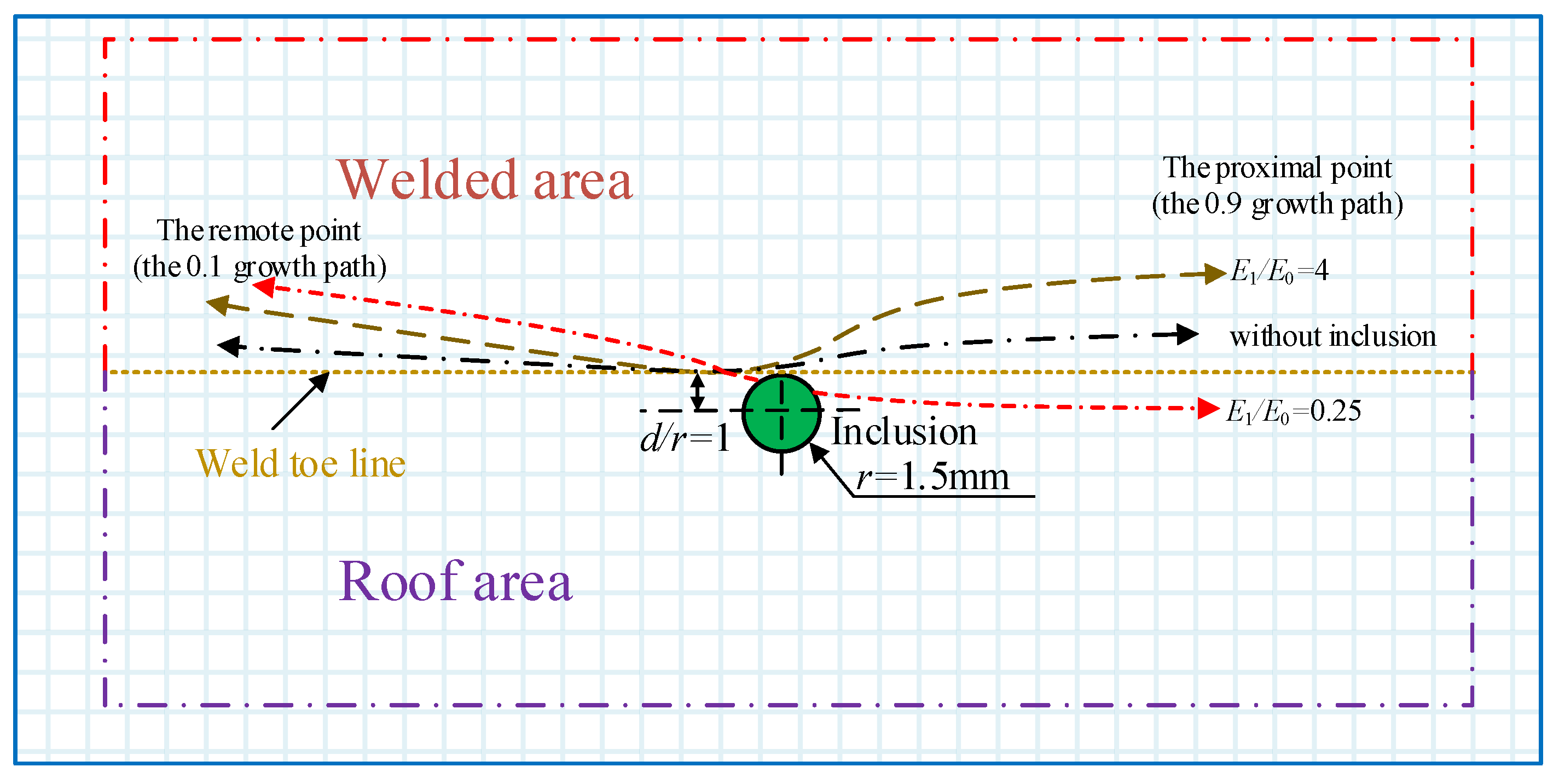
4.2.2. Effects of Crack–Inclusion on the Crack Growth Direction

The main crack in the joint weld generally grows perpendicular to the direction of stress loading. However, factors such as stress state and welding defects can impact the crack growth direction. As a result, the crack may deviate from the main growth direction and exhibit deflection, such as bifurcation and bridging [43]. With the increase in the SIFs for mode III, the growth direction of cracks is affected by inclusions to varying degrees, as shown in Figure 15.
It can be seen from Figure 15 that the elasticity modulus of inclusions has a significant influence on the crack growth direction. The fatigue crack grows in a mixed mode and deviates from its original growth direction to varying degrees. For cases with no inclusion and stiff inclusion, the crack tends to be biased towards the welded area. However, stiff inclusion will result in a greater deflection compared to the case without inclusions. On the other hand, soft inclusion attracts the proximal point to grow towards the roof area, while repeling the remote point growing towards the welded area. It is important to note that the repulsion effect of soft inclusions at the remote point of the crack is more pronounced than that of stiff inclusions, which is consistent with the result calculated in Figure 14b. The above conclusions can be applied to control the direction of crack growth, effectively diverting it away from the most critical path and thereby delaying or preventing the occurrence of complete fracture to a significant degree.
The deflection of the crack growth direction is often accompanied by a decrease in the crack growth rate. As shown in Figure 16, the deflection of the crack growth direction has a more significant impact on the growth rate in the length direction compared to the crack depth direction. Specifically, the growth rate of the proximal point increases in the order of soft inclusion, no inclusion, and stiff inclusion. The growth rate of the remote point increases in the order of the soft inclusion, the stiff inclusion, and no inclusion. The phenomena demonstrate that individual inclusions have minimal impact on crack fatigue life. In addition, the degree of crack deflection resulting from inclusions has a negative correlation with the crack growth rate.

5. Conclusions

This study investigated crack–inclusion interaction for rib-to-deck welded joints in OSDs based on numerical simulation and linear elastic fracture mechanics. A refined finite element model of a half U-rib with cracks and inclusions was established by using the FRANC3D-ABAQUS interactive technology. The full processes of the crack–inclusion interaction from approaching and penetrating were accurately simulated. The effects of inclusion on significant parameters, such as the SIFs, the shape factor, the growth rate, and the growth direction were analyzed.
The numerical results indicate that fatigue crack growth in welds is unstable due to inclusions. The stiff and soft inclusions amplify and shield the SIF of cracks when the crack grows to the local area of inclusions. During the entire process of crack growth, the soft and stiff inclusion accelerate and inhibit the crack growth, respectively. The magnitude of shielding and amplification effects is related E1/E0 and the distance between the cracks and inclusions. Stiff inclusions lead to asymmetric growth of the crack shape. The flattening of the crack increases by 22% in regions farther away from the inclusion compared to those closer to it. Inclusions strengthen the attribute of mixed-mode cracks. Compared with the fatigue life, the deflection effect of inclusions on the crack growth direction deserves more investigation. Soft and stiff inclusions attract and repel the growth direction of the proximal point of the crack, respectively.
Further investigations will be conducted in the following respects. The stochastic parameters of inclusion, such as the location, the size, and the shape are crucial for understanding crack growth characteristics. Experimental studies are necessary to validate the fatigue crack growth characteristics under welding defects. In the context of real bridge detection, it is crucial to consider the probabilistic characteristics of welding defects. The chemical composition of the steel, the welding method, and the microstructure of the material will be considered and investigated in future studies.

Author Contributions

Y.L. plays a guiding role in theoretical analysis; X.X. was responsible for the structural analysis and technical guidance; X.L. was responsible for data analysis and curation; F.C. and H.Z. were responsible for writing—review and editing. All authors have read and agreed to the published version of the manuscript.

Funding

This research was funded by the Natural Science Foundation of Hunan Province, China (No. 2023JJ50180 and 2023JJ50188), the Scientific Research Project of Hunan Provincial Department of Education (No. 22C0300; and 22B0567), and Zhuzhou Xiaohe Action Special Project.

Data Availability Statement

Not applicable.

Conflicts of Interest

The authors declare no conflict of interest.

References

  1. Da, L.T.; Zhang, Q.H.; Yuan, D.Y.; Ma, Y.; Cui, C. A new orthotropic steel deck system incorporating two novel structural details. J. Constr. Steel. Res. 2022, 199, 107633. [Google Scholar] [CrossRef]
  2. Luo, P.; Zhang, Q.; Bao, Y.; Bu, Y. Fatigue performance of welded joint between thickened-edge U-rib and deck in orthotropic steel deck. Eng. Struct. 2019, 181, 699–710. [Google Scholar] [CrossRef]
  3. Tsakopoulos, P.A.; Fisher, J.W. Full-scale fatigue tests of steel orthotropic decks for the Williamsburg Bridge. J. Bridge. Eng. 2003, 8, 323–333. [Google Scholar] [CrossRef]
  4. Bhardwaj, S.; Ratnayake, R.C. Residual stress estimation in defect assessment procedures at weld toe and away locations on girth welds: Review of key parameters. Theor. Appl. Fract. Mec. 2021, 111, 102848. [Google Scholar] [CrossRef]
  5. Shao, C.; Cui, H.; Lu, F.; Li, Z. Quantitative relationship between weld defect characteristic and fatigue crack initiation life for high-cycle fatigue property. Int. J. Fatigue 2019, 123, 238–247. [Google Scholar] [CrossRef]
  6. Wang, D.; Xiang, C.; Ma, Y.; Chen, A.; Wang, B. Experimental study on the root-deck fatigue crack on orthotropic steel decks. Mater. Des. 2021, 203, 109601. [Google Scholar] [CrossRef]
  7. Yao, Y.; Ji, B.; Fu, Z.; Zhou, J.; Wang, Y. Optimization of stop-hole parameters for cracks at diaphragm-to-rib weld in steel bridges. J. Constr. Steel. Res. 2019, 162, 105747. [Google Scholar] [CrossRef]
  8. Fang, Z.; Ding, Y.; Wei, X.; Li, A.; Geng, F. Fatigue failure and optimization of double-sided weld in orthotropic steel bridge decks. Eng. Fail. Anal. 2020, 116, 104750. [Google Scholar] [CrossRef]
  9. Gao, W.B.; Su, Q.K.; Zhang, J.W.; Xie, H.B.; Wen, F.; Li, F.; Liu, J.Z. Steel Bridge Construction of Hong Kong–Zhuhai–Macao Bridge. Int. J. Steel. Struct. 2020, 20, 1498–1508. [Google Scholar] [CrossRef]
  10. Xu, Y.; Wang, Z. Visual sensing technologies in robotic welding: Recent research developments and future interests. Sensore. Actuat. A Phys. 2021, 320, 112551. [Google Scholar] [CrossRef]
  11. Farreras-Alcover, I.; Chryssanthopoulos, M.K.; Andersen, J.E. Data-based models for fatigue reliability of orthotropic steel bridge decks based on temperature, traffic and strain monitoring. Int. J. Fatigue 2017, 95, 104–119. [Google Scholar] [CrossRef]
  12. Heng, J.; Zheng, K.; Feng, X.; Veljkovic, M.; Zhou, Z. Machine Learning-Assisted probabilistic fatigue evaluation of Rib-to-Deck joints in orthotropic steel decks. Eng. Struct. 2022, 265, 114496. [Google Scholar] [CrossRef]
  13. Zhu, J.; Zhang, W.; Li, X. Fatigue damage assessment of orthotropic steel deck using dynamic Bayesian networks. Int. J. Fatigue 2019, 118, 44–53. [Google Scholar] [CrossRef]
  14. Cui, C.; Ma, Y.; Zhang, Q.H.; Da, L.T.; Han, S.H. Fatigue strength and crack growth of double-side welded rib-to-deck joint in orthotropic steel decks. J. Constr. Steel. Res. 2022, 196, 107444. [Google Scholar] [CrossRef]
  15. Liu, Y.; Chen, F.; Lu, N.; Wang, L.; Wang, B. Fatigue performance of rib-to-deck double-side welded joints in orthotropic steel decks. Eng. Fail. Anal. 2019, 105, 127–142. [Google Scholar] [CrossRef]
  16. Abdelbaset, H.; Cheng, B.; Tian, L.; Li, H.T.; Zhang, Q.H. Reduce hot spot stresses in welded connections of orthotropic steel bridge decks by using UHPC layer: Experimental and numerical investigation. Eng. Struct. 2020, 220, 110988. [Google Scholar] [CrossRef]
  17. Cheng, B.; Abdelbaset, H.; Li, H.T.; Tian, L.; Zhao, J. Fatigue behavior of rib-to-floorbeam welded connections in UHPC reinforced OSDs subjected to longitudinal flexural. Eng. Fail. Anal. 2022, 137, 106383. [Google Scholar] [CrossRef]
  18. Fang, L.; Fu, Z.; Ji, B.; Fan, J. Reinforcement Effect of High-Strength Bolts for Stop-Hole under Out-of-Plane Bending Loads. J. Bridge. Eng. 2023, 28, 04022129. [Google Scholar] [CrossRef]
  19. Liu, J.; Liu, M.; Ma, S.; Tu, J. Study on in-plane double-crack propagation in the rib-to-deck weld toe of steel-bridge. J. Constr. Steel. Res. 2023, 203, 107838. [Google Scholar] [CrossRef]
  20. Zeng, Y.; He, H.; Qu, Y.; Sun, X.; Tan, H.; Zhou, J. Numerical Simulation of Fatigue Cracking of Diaphragm Notch in Orthotropic Steel Deck Model. Materials 2023, 16, 467. [Google Scholar] [CrossRef]
  21. Yang, H.; Wang, P.; Qian, H.; Niu, S.; Dong, P. A study of fatigue crack propagation paths at U-rib welds in orthotropic bridge decks using a phased-array imaging technique. Theor. Appl. Fract. Mec. 2022, 119, 103310. [Google Scholar] [CrossRef]
  22. Yagi, K.; Tanaka, S.; Kawahara, T.; Nihei, K.; Okada, H.; Osawa, N. Evaluation of crack propagation behaviors in a T-shaped tubular joint employing tetrahedral FE modeling. Int. J. Fatigue 2017, 96, 270–282. [Google Scholar] [CrossRef]
  23. Gadallah, R.; Osawa, N.; Tanaka, S.; Tsutsumi, S. Critical investigation on the influence of welding heat input and welding residual stress on stress intensity factor and fatigue crack propagation. Eng. Fail. Anal. 2018, 89, 200–221. [Google Scholar] [CrossRef]
  24. Wang, B.; Nagy, W.; De Backer, H.; Chen, A. Fatigue process of rib-to-deck welded joints of orthotropic steel decks. Theor. Appl. Fract. Mec. 2019, 101, 113–126. [Google Scholar] [CrossRef]
  25. Lu, N.; Liu, J.; Wang, H.; Yuan, H.; Luo, Y. Stochastic propagation of fatigue cracks in welded joints of steel bridge decks under simulated traffic loading. Sensors 2023, 23, 5067. [Google Scholar] [CrossRef]
  26. Wang, B.; Zhou, X.Y.; Chen, A. Probabilistic study on the macro-crack initiation of the rib-to-deck welded joint on orthotropic steel deck. Int. J. Fatigue 2020, 139, 105721. [Google Scholar] [CrossRef]
  27. Guo, J.; Hang, D.; Zhu, X. Prediction of crack propagation in U-rib components based on the Markov chain. J. Bridge. Eng. 2020, 25, 04020089. [Google Scholar] [CrossRef]
  28. Wang, B.; Zhou, X.Y.; De Backer, H.; Chen, A.; Schmidt, F. Macro-crack initiation life for orthotropic steel decks considering weld heterogeneity and random traffic loading. Struct. Infrastruct. Eng. 2017, 13, 1639–1652. [Google Scholar] [CrossRef]
  29. Yau, J.F. A mixed-mode crack analysis of isotropic solids using conservation laws of elasticity. J. Appl. Mech. 1987, 47, 615–642. [Google Scholar] [CrossRef]
  30. Lv, F.; Zhou, C.Y.; Cheng, R.J.; Miao, X.T.; He, X.H. A numerical analysis based on M-integral about the interaction of parallel surface cracks in an infinite plate. Theor. Appl. Fract. Mec. 2018, 96, 370–379. [Google Scholar] [CrossRef]
  31. Paris, P.; Erdogan, F. A critical analysis of crack propagation laws. J. Basic Eng. 1963, 85, 528–533. [Google Scholar] [CrossRef]
  32. Wang, G.; Ma, Y.; Guo, Z.; Bian, H.; Wang, L.; Zhang, J. Fatigue life assessment of high-strength steel wires: Beach marks test and numerical investigation. Constr. Build. Mater. 2022, 323, 126534. [Google Scholar] [CrossRef]
  33. Ye, H.; Duan, Z.; Tang, S.; Yang, Z.; Xu, X. Fatigue crack growth and interaction of bridge wire with multiple surface cracks. Eng. Fail. Anal. 2020, 116, 104739. [Google Scholar] [CrossRef]
  34. Abdelbaset, H.; Cheng, B.; Xiang, S.; Tian, L. An investigation on fatigue crack propagation behavior of welded connections in UHPC reinforced OSDs using 3D crack simulation. Structures 2023, 50, 1527–1544. [Google Scholar] [CrossRef]
  35. Newman, J.C., Jr.; Raju, I.S. An empirical stress-intensity factor equation for the surface crack. Eng. Fract. Mech. 1981, 15, 185–192. [Google Scholar] [CrossRef]
  36. GB50017-2017; Standard for Design of Steel Structures. Ministry of Housing and Urban-Rural Construction of the People’s Republic of China: Beijing, China, 2017.
  37. Hobbacher, A. Recommendation for Fatigue Design of Welded Joints and Components; Spring International Publishing: Cham, Switzerland, 2016. [Google Scholar]
  38. Wang, Y.; Zhang, L.; Ren, Y.; Li, Z.; Slater, C.; Peng, K.; Liu, F.; Zhao, Y. Effect of compression temperature on deformation of CaO–CaS–Al2O3–MgO inclusions in pipeline steel. J. Mater. Res. Technol. 2021, 11, 1220–1231. [Google Scholar] [CrossRef]
  39. Jiang, X.; Sun, K.; Qiang, X.; Li, D.; Zhang, Q. XFEM-based Fatigue Crack Propagation Analysis on Key Welded Connections of Orthotropic Steel Bridge Deck. Int. J. Steel. Struct. 2023, 23, 404–416. [Google Scholar] [CrossRef]
  40. BS7910; Guide on Methods for Assessing the Acceptability of Flaws in Metallic Structures. British Standards Institution: London, UK, 2013.
  41. BS7608; Guide to Fatigue Design and Assessment of Steel Products. British Standards Institution: London, UK, 2015.
  42. Fang, L.; Fu, Z.; Ji, B.; Gao, Y. Fatigue crack-propagation law of diaphragm-to-rib welded joint in steel bridge deck. J. Constr. Steel. Res. 2022, 194, 107311. [Google Scholar] [CrossRef]
  43. Jian, H.; Wang, Y.; Yang, X.; Xiao, K. Microstructure and fatigue crack growth behavior in welding joint of Al-Mg alloy. Eng. Fail. Anal. 2021, 120, 105034. [Google Scholar] [CrossRef]
Figure 1. A finite width plate with semi-elliptical crack.
Metals 13 01402 g001
Figure 2. Dimension of a suspension bridge: (a) overall view; (b) a half cross-section.
Metals 13 01402 g002
Figure 3. Detail of rib-to-deck: (a) dimension diagram (mm); (b) typical cracks at welded joints.
Metals 13 01402 g003
Figure 4. The FE model developed by F-A technology.
Metals 13 01402 g004
Figure 5. Schematic diagram of defect distribution: (a) 3D view; (b) vertical view.
Metals 13 01402 g005
Figure 6. Stress distribution around cracks (unit: MPa): (a) no inclusion; (b) with a soft inclusion; (c) with a stiff inclusion.
Metals 13 01402 g006aMetals 13 01402 g006b
Figure 7. Variation in SIFs without inclusion.
Metals 13 01402 g007
Figure 8. Variation in the SIF influence factor λ on the 0.9 growth path.
Metals 13 01402 g008
Figure 9. Variation in the SIFs with d: (a) E1 = 0.25E0; (b) E1 = 4E0.
Metals 13 01402 g009
Figure 10. Growth rate of crack of mode-Ⅰ.
Metals 13 01402 g010
Figure 11. The ratio of c/a as a function of a.
Metals 13 01402 g011
Figure 12. Evolution of crack shape: (a) without inclusion; (b) with a soft inclusion; (c) with a stiff inclusion.
Metals 13 01402 g012
Figure 13. SIFs of mixed-mode cracks in homogeneous materials (at the crack tip along the long axis of the crack).
Metals 13 01402 g013
Figure 14. Variations in KIII/KI: (a) at the proximal point; (b) at the remote point.
Metals 13 01402 g014aMetals 13 01402 g014b
Figure 15. The effect of inclusion on crack growth direction.
Metals 13 01402 g015
Figure 16. Growth rate of mixed-mode cracks.
Metals 13 01402 g016
Table 1. Comparison results of the plate example.
a/cPointThe Calculated Value of SIF (MPa·mm1/2)Relative Error
FRANC3DNewman
0.2T67.89 69.22 1.93%
D47.67 46.38 −2.78%
0.3T92.82 94.21 1.47%
D67.18 66.37 −1.22%
0.4T108.01 109.96 1.77%
D83.90 83.94 0.04%
0.5T117.83 120.27 2.03%
D99.28 99.19 −0.08%
0.6T124.66 126.90 1.76%
D112.53 112.37 −0.15%
Disclaimer/Publisher’s Note: The statements, opinions and data contained in all publications are solely those of the individual author(s) and contributor(s) and not of MDPI and/or the editor(s). MDPI and/or the editor(s) disclaim responsibility for any injury to people or property resulting from any ideas, methods, instructions or products referred to in the content.

