Article

Features of Structure and Properties of Lap-Welded Joints of Aluminum Alloy Al–4Cu–1Mg with Titanium Alloy Ti–6Al–4V, Obtained by Friction Stir Welding

Institute of Strength Physics and Materials Science of the Siberian Branch of the Russian Academy of Sciences, pr. Akademicheskii, 2/4, Tomsk 634021, Russia
*
Authors to whom correspondence should be addressed.
Metals 2023, 13(8), 1385; https://doi.org/10.3390/met13081385
Submission received: 20 June 2023 / Revised: 26 July 2023 / Accepted: 27 July 2023 / Published: 1 August 2023
(This article belongs to the Special Issue Feature Papers in Welding & Joining)

Abstract

:
Lap-welded joints between Ti–6Al–4V and Al–4Cu–1Mg were obtained using water-cooling-bath friction stir welding at different FSW tool rotation rates. The increase in the tool rotation rate from 350 to 375 RPM leads to better plasticization of the titanium alloy, elimination of stir zone defects, better interlocking and bonding with the aluminum alloy as well as the formation of intermetallic Al–Ti compounds (IMC), preferentially of the Al3Ti type. Shear-loading testing showed the best result was at the level of 3000 N with 2 mm of displacement. Increasing the FSW tool rotation rate to 400 and 450 RPM resulted in the formation of more IMCs, which had a detrimental effect on both maximum load and displacement achieved in the shear tests.

1. Introduction

Titanium and aluminum alloys are widely used in critical structures of aerospace industry because they possess high specific strength and corrosion resistance, and therefore, they can sustain rather harsh operating conditions. In addition, the dissimilar Ti/Al welding joints would be useful to increase the efficiency of their use. For example, critical elements of a welded structure may be made of high-strength titanium alloys with supporting elements made of aluminum alloys. Such a combination of properties of two dissimilar alloys makes it possible to optimize the weight and dimensions of the structure while maintaining all the required operating characteristics.
Using fusion welding of dissimilar materials is associated with the appearance of gas and shrinkage porosity, intermetallic inclusions, changes in phase composition during metal cooling, and internal stresses [1,2].
At the same time, friction stir welding (FSW) is intensively used for welding dissimilar materials without melting them [3,4]. Investigations into structural-phase states of welded joints and mechanisms of their formation are being carried out widely. The major part of research in this field is devoted to the investigation of friction stir welding on commercial aluminum alloys, while titanium alloys are harder to weld because of the high temperatures needed to plasticize them, and therefore, more stable FSW tool materials are required. Diffusion-controlled interaction between FSW tool materials and plasticized titanium alloys results in the formation of intermetallic compounds (IMC), which may intermix with the stir zone metal [5,6] and, thus, affect the strength characteristics of the fixed joints. The studies of the kinetics of the formation of welded joints, which provides redistribution of structural elements of welded materials, demonstrate that increasing the intensity of FSW thermomechanical impact effects on the redistribution of welded materials makes it more complicated, with the formation of vortex structures and increasing the total area of contact between materials [7]. In addition, all these effects may vary with the FSW process parameters [8,9,10].
The key problem of dissimilar welding of titanium and aluminum is the physical and mechanical interaction of materials, which is accompanied by the formation of excessive IMCs of different compositions (TixAly) in the stir zone, which may have a detrimental effect on the joint strength. One study [11] showed that with the increase in the tool rotation frequency and temperature in the stir zone, the thickness of the diffusion layer increases, thus changing the phase composition of IMCs and affecting the joint strength. The intensification of the diffusion interaction and the formation of IMCs with the increasing of the stir zone temperature has its effect on the welding [12,13]. Another study [14] showed that the intensity of the thermomechanical impact in FSW determines the non-uniformity of titanium distribution in aluminum as well as the intensity of associated diffusion processes.
Dissimilar FSW joints between aluminum alloy Al–1Mg–Si–Cu and titanium alloy Ti–6Al–4V were obtained and investigated [15]. It was shown that an intermediate layer containing micropores and microcracks formed between the welded materials when the tool rotation frequency increased, thus leading also to the increase in the amount of IMCs, embrittlement and reduction of the welded joint strength. Dissimilar Al–4Cu–1Mg /Ti–6Al–4V butt joints were obtained, depending on the welding speed, and with a maximum tensile strength of 348 MPa [16,17]. The changes in the shape and size of grains in the titanium alloy were observed only in the layer adjacent to the joint line, while in the aluminum alloy all the characteristic structural zones were present. During the FSW, vortex-like structures of a few micrometers in size were formed, in which the redistribution of materials occurred. A detailed investigation of such particles showed the presence of mechanical adhesion between the dissimilar materials. The formation of a thin (2–5 μm of thickness) Al3Ti IMC layer at the Ti/Al interfaces, which impaired the joint strength, was shown in [18,19].
One of the methods that allow reducing the amount and size of the IMCs formed in FSW is sonication of the Ti/Al FSW lap joints [20,21,22]. The sonication in FSW allows the generation of more crystalline lattice defects and also increases their mobility, which, on the one hand, allows increasing the number of IMC nuclei, but on the other hand, intensifies the diffusion of atoms. In fact, during the FSW the IMCs continuously precipitate and dissolve in the stir zone, while IMC precipitation surpasses their strain dissolution in the thermomechanically affected and heat-affected zones where coarse IMC usually form.
In general, the phenomena that occur in dissimilar friction stir welding of aluminum- and titanium alloys may be as follows: hot plastic deformation serves to generate dislocations, which then participate in the grain boundary slip of refined grains and subgrains, which experience dynamic recrystallization under intensive convection and diffusion mass transfer processes [23]. As a result of dynamic recrystallization and shear deformation of material, a refinement of structural grains with the formation of a large number of high-angle boundaries on which diffusing atoms form intermetallic particles occurs. With an increase in intensity of the stir zone temperature, the amount of IMCs increases, thus forming an IMC layer, which has weak adhesion with the surrounding metal and leads to loss of the joint strength by embrittlement. The intensity of the thermomechanical impact may be controlled by changing the FSW parameters such as speed of rotation and speed of movement of a welding tool, its axial force, its location during welding, etc. [24,25,26]. In its turn, the intensity of stirring controls the associated processes of strain-induced dissolution and precipitation of IMCs, dynamic recrystallization and growth of grains.
Another route to go with the IMC amount reduction may be extra cooling of the stir zone and thus reducing the intensity of diffusion without creating extra IMC nucleation centers [27]. This approach was used within a framework of the present work on friction stir welding of aluminum alloy Al–4Cu–1Mg with titanium alloy Ti–6Al–4V.

2. Materials and Methods

2.1. Experimental Equipment and Materials

Friction stir welding was performed on the experimental equipment for FSW using water stream cooling of the stir zone according to the scheme in Figure 1. Immersion of the welded material in the cooling liquid made it possible to reduce heating of the aluminum alloy and to prevent the formation of defects due to its overheating. The plate of aluminum alloy Al–4Cu–1Mg (chemical composition is presented in Table 1) was placed on the plate of titanium alloy Ti–6Al–4V (chemical composition is presented in Table 2). Data on chemical composition of both alloys were obtained using an x-ray fluorescent analyser Niton xl3t 980 GOLDD (ThermoFisher (Niton), Billerica, MA, USA).
The aluminum alloy plate with dimensions of 3.8 mm in thickness, 90 mm in width, and 200 mm in length, was milled from both sides to the depth of 0.9 mm to its full length before lap welding on a 200 mm × 90 mm × 2.5 mm plate of titanium alloy, as shown in Figure 1. This milling allowed the penetration of a pin 2.3 mm in height through the aluminum alloy plate and acting on the titanium substrate.
The FSW tool was made of heat-resistant nickel superalloy ZhS6U and had a ∅20 mm shoulder, a truncated cone pin 2.3 mm in height with its root and top diameters being ∅6 mm and ∅3 mm, respectively (Figure 2).
During the welding process, the tool was plunged at an inclination angle of 1.5°, as shown [28,29], into the aluminum alloy so that there was a gap between the leading edge of the tool shoulder and the workpiece. After plunging, the penetration force was increased by 2 kN, the tool was rotated with the given frequency and then the tool was moved along the joint centerline line at the given speed. The plunging force was maintained constant until reaching the end of the seam, which allowed controlling the FSW tool penetration into the titanium alloy sheet. In addition, moment of friction and welding resistance force were recorded to control the plasticization and heat release.
Table 3 contains FSW parameters used for obtaining the dissimilar lap joints: ω is the frequency of tool rotation, Fp is the axial force on the tool during plunging stage, Fw is the axial force on the tool during welding, V is the speed of welding, L is the weld length. These parameters were chosen from preliminary experimenting.

2.2. Investigation Methods

The specimens for structural investigations were cut out from the obtained joints in a plane perpendicular to the welding direction, followed by grinding and diamond paste polishing. Then, these specimens were subjected to etching in a solution prepared from HCl-6 mL, HNO3--8 mL, HF-4 mL, H2O-82 mL for 30 s.
Metallographic images of the structure of welded joints were obtained using an optical microscope “Altami Met 1S” (Altami Ltd., Saint Petersburg, Russia). Images of fracture surfaces after mechanical testing were obtained on a high-resolution scanning electron microscope with field emission (FEG SEM), Apreo 2 S (Thermo Fisher Scientific, Waltham, MA, USA), equipped with energy-dispersive spectral analysis (EDS/EDX) detector Octane Elect Super (EDAX, Mahwah, NJ, USA). X-ray structural analysis was performed on the structures of both initial alloys and welded joints fractured during mechanical testing. The analysis was performed on an X-ray diffractometer DRON-7 (Burevestnik, S. Petersburg, Russia) at 36 kV and 22 mA using CoKα radiation with a wavelength of 1.7902 Å. During the scanning, the value of 2θ angles was changed within the range of 15–102° with steps of 0.05° and exposure time of 40 s. Peak identification and data processing were performed using Crystal Impact’s “Match!” software (version 3.9).
Microhardness measurements were carried out using the microhardness tester “Affairs DM8” (Affairs, Varese, Italy) with a load on an indenter of 50 kN for 10 s. Measurements were carried out on the specimens prepared for metallographic investigations in the vertical direction with a step of 0.1 mm on 3 tracks on each specimen. Since welded joints are lap joints, they were subjected to shear tests at room temperature on a testing machine, UTS 110M-100 (Testsystems, Ivanovo, Russia). Loading speed was 1 mm/min for tensile tests.
Flat specimens cut across the welded joint, located in the center of the working area of the specimens, were made for testing. The schematic of the cutting out of the obtained specimens for mechanical tests and metallographic investigations is shown in Figure 3.

3. Results and Discussion

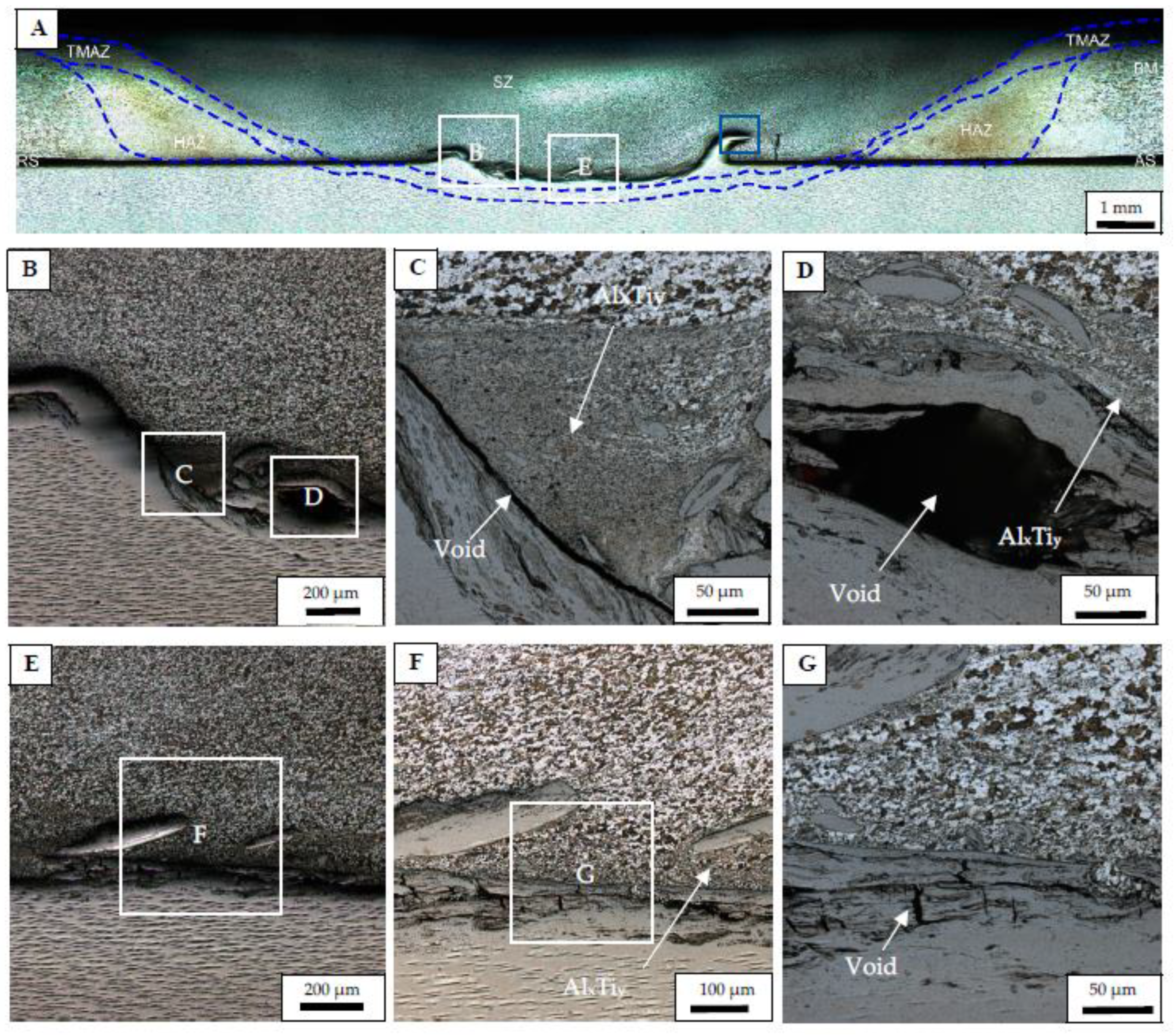
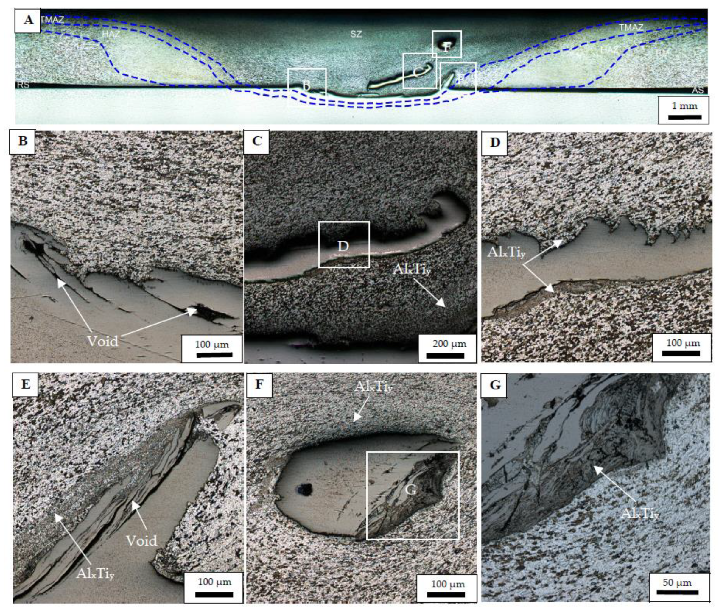
3.1. Features of the Structure of Welded Joints

During friction stir welding, the structure of the aluminum alloy underwent significant changes due to intensive thermomechanical impacts from the welding tool, while the structure of titanium alloy did not practically change. Therefore, the structure and elemental composition of the welded joints were studied in the vicinity of the aluminum/titanium alloy interface. As a result of etching, four zones were clearly distinguished and marked in the Al–4Cu–1Mg alloy region: the base metal zone (BM), heat-affected zone (HAZ), thermomechanically affected zone (TMAZ), and stir zone (SZ). The recrystallized grains are observed in the Al–4Cu–1Mg stir zone, while fine severely deformed grains are found in the TMAZ.
Figure 4 shows cross-section images of the structure of welded joint No. 1. The macrostructure of the joint is shown in Figure 4A. During the welding, the aluminum alloy penetrated to the depth of 0.2–0.3 mm into the titanium alloy in the area actuated by the tool pin. The stir zones of two FSWed alloys are characterized by the presence of material fragments. On the advancing side of the joint (AS), titanium alloy fragments are observed in the Al–4Cu–1Mg stir zone to the depth of ≤ 0.2 mm (Figure 4B). These fragments appear to be both isolated inside the base metal as well as connected with it. The IMCs in the form of a 20–50 µm thick layer are sporadically observed in the vicinity of the interface, as revealed by etching (Figure 4C).
On the retreating side of the joint (RS), fragments of titanium alloy are observed in the Al–4Cu–1Mg stir zone to the depth of ≤ 1.1 mm, being connected with the base metal (Figure 4D,E). At the same time, significantly more titanium alloy penetrated into the aluminum alloy on the retreating side of the joint compared to that on the advancing side. The distribution of the intermetallic layers is similar to that described above.
The mechanical Interaction of the alloys was predominantly by adhesive sliding (Figure 4C,F,G), because IMCs were found in relatively small amounts at the interface between two alloys. In the vicinity of the interface, the aluminum alloy is severely deformed, such that the alloy fragments separated from the base metal. There are voids of complex geometric shape located mainly inside the titanium alloy. Based on the structures observed, it is possible to state that under these welding conditions the FSW parameters did not provide the effective plasticization (heating) of the titanium alloy, which would be sufficient for its effective intermixing with aluminum alloy as well as for the intensification of diffusion processes responsible for the formation of IMCs.
Figure 5 shows cross-sectional microstructural images from the welded joint #2. The macrostructure of the joint is shown in Figure 5A. The aluminum alloy penetrated into the titanium alloy to the depth of 0.4 mm. Since this joint was obtained at the tool rotational rate increased up to 375 RPM, the welded alloys were subjected to a more intensive thermomechanical impact. This had its effect on the redistribution of the alloy fragments. Isolated titanium alloy fragments are observed on the retreating side as well as in the center of the joint (Figure 5B,E). The penetration of the titanium alloy with the formation of “hook-shaped” inclusions indicates its greater plasticization compared to that existing under welding conditions #1. Plastic deformation of the titanium alloy can be noticed in the vicinity of the interface with the aluminum alloy (Figure 5C,F). In addition, the increase in the amount of IMCs with the formation of a 50–100 μm thickness layer and the elimination of defects (Figure 5C,D,G) occurred. Thus, under the given welding conditions, the thermomechanical impact of FSW provides plasticization of titanium alloy and intensification of diffusion processes.
Figure 6 shows cross-sectional images of macro- and microstructures in the welded joint #3. The macrostructure of the joint is shown in Figure 6A. This joint was obtained at a tool rotation rate of 400 RPM, so the alloy intermixing pattern is different from those with both #1 and #2 FSW joints.
The “hook-shaped” titanium alloy structures were transformed into isolated fragments, which penetrated deeply into the aluminum alloy (Figure 6C,F). In turn, the IMC layers with a thickness of 20–50 μm were formed at their interfaces with the aluminum alloy (Figure 6D,F,G). On the advancing side of the joint, there are no titanium alloy inclusions; instead, there are defects in the form of voids and discontinuities (Figure 6B,E). An increase in the amount of IMCs with the formation of a 50–150 μm-thick layer is observed (Figure 6D,E,G). It can be noted that the thermomechanical impact of FSW provides a more intensive plasticization of the titanium alloy and intensification of diffusion processes in welding according to the FSW conditions used on sample #3.
Figure 7 shows cross-sectional images of the structure of welded joint #4. The macrostructure of the joint is shown in Figure 7A. This joint was obtained at a tool rotation rate 450 RPM, and its stir zone structure is similar to that of welded joint #3.
The formation of titanium alloy–isolated inclusions detached from the base metal is observed in the structure of the joint (Figure 7D,E). The IMC layers of a thickness up to 100 μm are formed at their interfaces with the aluminum alloy as well as those formed after FSW in sample #3. Formation of intermetallic bridges is also observed (Figure 7E–G). Defects in the form of voids formed in the layer-by-layer flow of the titanium alloy are practically not observed (Figure 7B,E). No deformed areas of the titanium alloy were detected either, which indicates a high degree of its plasticization during the welding process. In addition, the increase in quantity of IMCs with the formation of layers of variable thicknesses of up to 200 μm is observed (Figure 6D,E,G). It can be concluded that increasing the tool rotation rate to 450 RPM allows achieving a high degree of titanium alloy plasticization, which then ensures its easy flow and sliding interaction with the aluminum alloy. In parallel with this, an increase in the thickness of the intermetallic layers is observed.

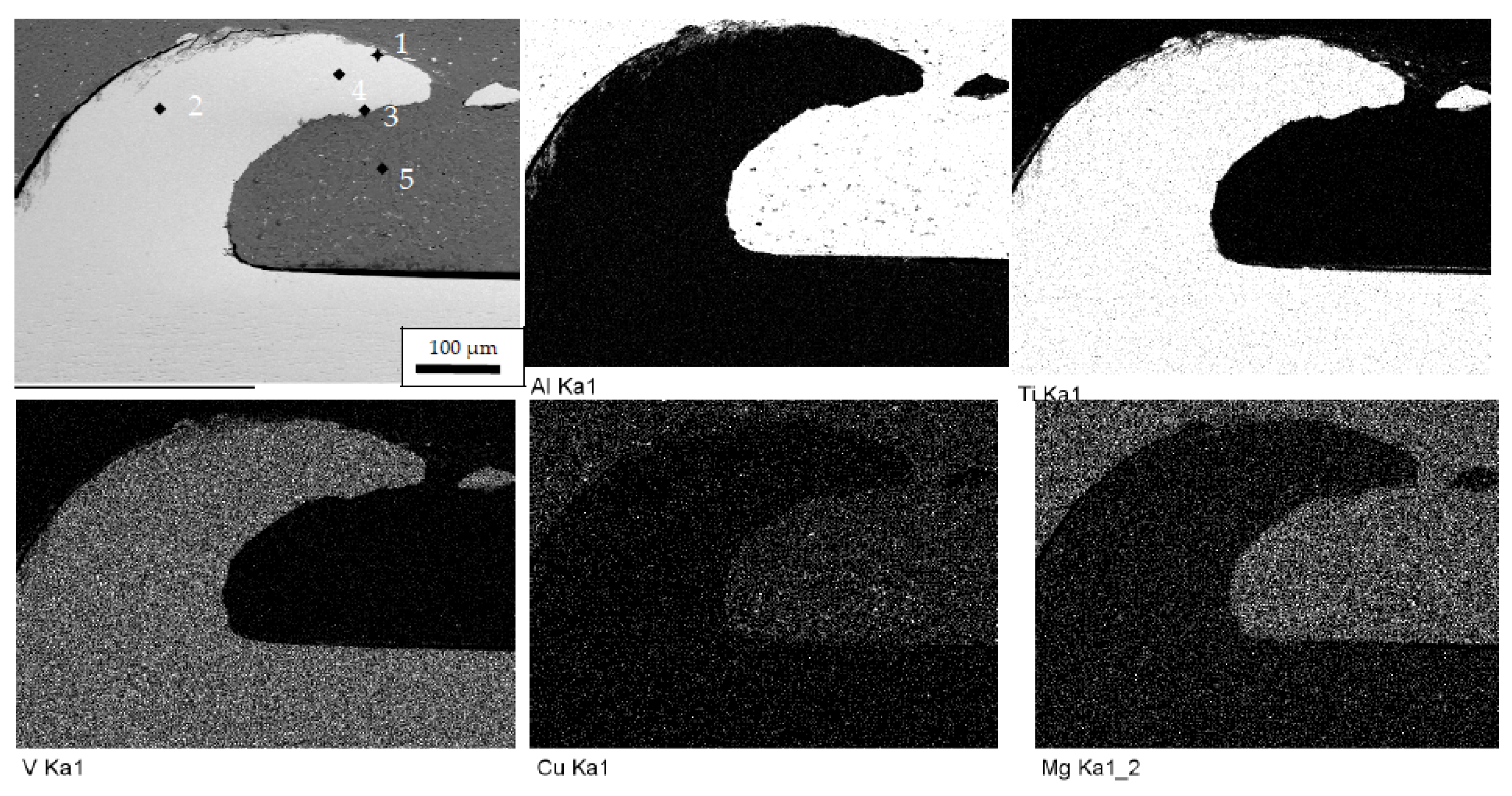
3.2. Elemental Composition of Welded Joints

Figure 8 shows the SEM images of the welded joint #1 in the region shown in Figure 4E, as well as the EDX maps of its main chemical elements. Table 4 shows also the EDX spectra obtained from points denoted by 1 to 7 in Figure 8.
According to the data obtained, both magnesium and copper are observed in the titanium alloy areas denoted by points 3, 5 and 6. At point 4, titanium is observed in the area of the aluminum alloy. Mutual diffusion of alloy components is observed, and aluminum alloy elements diffuse more intensively. This proves that the FSW parameters do not provide the thermomechanical impact necessary for admixing of Ti–6Al–4V alloy into Al–4Cu–1Mg alloy as well as for intensive diffusion of titanium alloy elements. It should be noted that, at points 3 and 6, the ratios of titanium and aluminum atomic concentrations correspond to those of either TiAl-type or TiAl3-type IMCs.
Figure 9 shows the SEM image of the welded joint #2 and EDX maps of its main chemical elements in the area containing the Ti–6Al–4V alloy hook in the Al–4Cu–1Mg alloy on the advancing side of the stir zone along with the corresponding EDX maps. The EDX spectra in areas denoted by points in Figure 9 (sample #2) are shown in Table 5.
According to the EDX results, both magnesium and copper are observed in the titanium alloy area 2, with the Ti/Al atomic concentration ratio corresponding to that of TiAl-type IMC. Near the interface, there are points 1 and 3, whose EDX spectra correspond to formation of solid solutions by mutual diffusion of both alloy’s elements. The atomic concentration Ti/Al ratio in the probe area 1 corresponds to that of TiAl3-type IMC. As in probe area 6 of the FSW joint #1, this region is the interface between the two alloys. Thus, in comparison with the sample #1, the diffusion of the aluminum alloy components is intensified, which is caused by the greater effect of frictional heating at the increased tool rotation rate.
Figure 10 shows the SEM image of the welded joint #3 in the region shown in Figure 6G, as well as EDX maps of its main chemical elements. The results of the elemental analysis in corresponding areas denoted by points in Figure 10 are shown in Table 6.
According to the data obtained, the elemental composition of the considered joint region is caused by intense mutual diffusion of the components of both alloys. The EDX spectra obtained from areas 2, 4 and 6 allow identifying the Ti/Al atomic concentration ratio as 1:2, which indicates the possible formation of the TiAl2-type IMCs. In the area denoted by point 3, this ratio is 1:1, which may correspond to the formation of the TiAl-type IMC. Analyzing the results, we can make a conclusion about the intensive process of mutual diffusion of the components of both alloys, caused by an increase in the rotation frequency of the welding tool.
Figure 11 shows the SEM image of the welded joint #4 in the region shown in Figure 7G, as well as EDX maps of its main chemical elements. The results of the EDX elemental analysis in special points (Figure 11) are shown in Table 7.
According to the data obtained, a further increase in the FSW tool rotation rate enhances the diffusion processes even more to form more IMCs. The Ti/Al atomic concentration ratio (Table 7) allows suggesting the formation of a number of IMCs, such as TiAl2 and Ti2Al5 according to spectrum 1 and spectrum 2, respectively. Spectra 3 and 4 allow suggesting the formation of Ti3Al and TiAl3 IMCs, respectively.
Increasing the intensity of the FSW thermomechanical impact resulted not only in increasing the IMC amount but also changed their stoichiometry towards a higher atomic concentration of titanium, in accordance with the Ti–Al phase diagram. This means that increasing the thermomechanical impact of the FSW leads to better diffusive mobility of the titanium, which allows the forming of IMC according to the following order: α(Ti)→AlTi3→Al2Ti→Al5Ti2→AlTi→AlTi3→α-Al(Ti). The presence of the latter phase, α2-AlTi3 with a wide homogeneity region, may be desirable for attaining plasticity to brittle high-temperature γ-TiAl-base alloys, but when formed in a Ti–Al–Mn coating it increased the adhesive wear intensity [30].

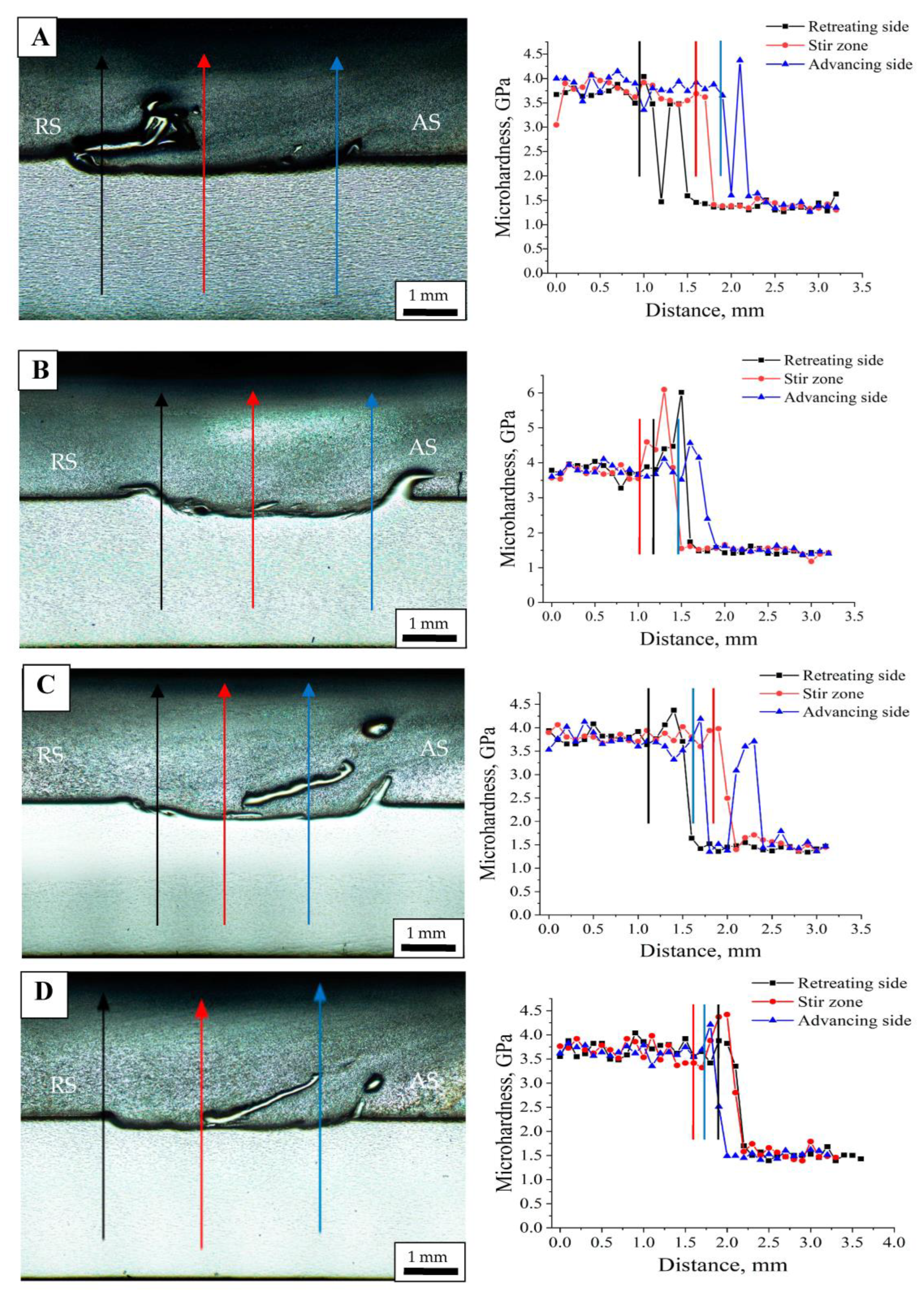
3.3. Strength Properties of Welded Joints

The results of mechanical shear tests of the welded joints are shown in Figure 12. During the tests, it was found that the FSW joints were characterized by brittle fracture. The lowest values of joint failure load and relative displacement of the plates were observed on the welded joint #1. This may be explained by insufficient bonding between the alloys as well as the presence of defects which formed due to insufficient plasticization of the titanium alloy.
The highest values of failure load and displacement of alloy plates relative to each other were observed during tests of the FSW joint #2. This is caused by elimination of structural defects, as well as by efficient plasticization of the titanium alloy, which then more effectively intermixed and bonded to the aluminum alloy. The accompanying intensification of diffusion processes contributes to the formation of some IMCs whose amount and morphology, however, did not result in severe embrittlement of the interface region.
In FSW of joints #3 and #4, obtained by sequentially increasing the tool rotation frequency, plasticization of titanium and intensification of IMC formation was even greater compared to those in FSW on sample joint #2. The IMC quantity and layer morphology provided a notable embrittlement. In addition, some structural defects were formed in the FSW joint #3 due to improper titanium alloy flow, which causes a decrease in its resistance to the fracture load. No such defects were found in joint #4, but the number of intermetallic compounds increased. As a result of the combined effect of these factors, an increase in the value of the fracture load with a decrease in the value of the mutual displacement of the alloy plates is observed during the tests.
Vickers microhardness profiles were obtained by indenting along the lines shown in Figure 13A–D micrographs. Quasiperiodic changes of microhardness numbers are observed on both retreating and advancing sides of the stir zone of joint #1 (Figure 13A), but the mean hardnesses correspond to those of base alloys. The interface between two alloys is shown by lines of corresponding color on the microhardness plots (Figure 13A) that allows observing the penetration of the titanium alloy into the aluminum alloy to a considerable depth. Since no IMCs were detected in this transition region then, there are no high-hardness number peaks.
These 4.5–6 GPa high peaks were, however, detected in the microhardness profile obtained from FSW joint #2 (Figure 13B) in the region where two alloys interacted, with the formation of IMCs.
Note that high microhardness peaks were detected in joints # 3 and # 4 (Figure 13C,D). An explanation may be the formation of more ductile Ti-enriched IMCs. Some higher 4.0 GPa peaks are observed in the transition zone of sample joint #4, which may be related to TiAl particles.

3.4. Fractography

Figure 14 shows the fracture surface of the welded joint #2 specimen after its shear test. Figure 14A shows a general view of the fracture surfaces, and Figure 14B,C show fracture surface images on the Al–4Cu–1Mg and Ti–6Al–4V alloy side, respectively. The fracture surface features indicate the brittle fracture of the welded joint under shear loading. These fractographic findings are typical of all the joints investigated.
Figure 15 shows the XRD patterns obtained from the fracture surfaces of the shear-tested welded joints on the sides of titanium and aluminum alloys. In addition to those of α-Al, and α-Ti solid solutions, there are TiAl3 IMC peaks on all the diffractograms that allow suggesting the brittle fracture mechanism.
Semi-quantitative phase contents left on the fracture surface were determined using the XRD peak intensities of α-Ti, Al and β-Al3Ti phases R(x) as calculated from formula (1):
R ( x ) = I ( x ) / I ( A )
where I(x) is the intensity of the ‘x’ phase reflection related to the ΣI(A) sum of all reflection intensities.
The maximum of aluminum content was found on the Al–4Cu–1Mg side of joint #1 with minimum of α-Ti and some amount of Al3Ti (Figure 16). It is suggested that either the bonding was too weak or the area of bonding was also not high enough to provide good shear strength. The Ti–6Al–4V alloy side contains almost equal amounts of α-Ti and α-Al as well as a smaller amount of Al3Ti, which undoubtedly was formed inside the Ti–6Al–4V alloy as a result of intermixing and diffusion in the form of α-Ti(Al)+Al3Ti structures. The fracture surfaces of joint #2 are characterized by increasing amounts of α-Ti (both sides) and less of α-Al on the Al–4Cu–1Mg side with almost the same level of Al3Ti and somewhat lower amounts of α-Ti than that on the Ti–6Al–4V side. The amount of α-Al becomes higher on the Al–4Cu–1Mg side of joint #3 and, vice versa, the amount of α-Ti is somewhat less. The Ti–6Al–4V side bears more α-Ti and less α-Al as compared to those of joint #2. The amount of all components on the fracture surfaces of joint #4 are almost the same as those for joint #2.
The amounts of components left on the fracture surfaces after the shear testing may characterize the degree of bonding between the alloys. The presence of more aluminum or titanium means that fracture occurred inside the aluminum or titanium part of the joint. The exception here may be when the fracture occurred by the interface with some minor bonding bridges. In such a case, the XRD will show the presence of almost pure alloys with minor amounts of IMCs or solid solutions. We suggest this is what occurred with joint #1 made with insufficient plasticization.
According to the Al–Ti phase, aluminum is dissolved in titanium with the formation of α-Ti(Al) solid solution and then Ti3Al IMC. The Al-rich end of the diagram shows the formation of brittle Al3Ti IMC, which was always detected in our experiments as a result of intermixing and diffusion. It is no surprise that this brittle IMC was found on both fracture surfaces together with the α-Al matrix. In fact, the measurements show that the amount of α-Al on the Ti–6Al–4V side is almost constant for all the joints obtained.
The amount of brittle deleterious Al3Ti left on the Ti–6Al–4V side is reduced for sample joints #2 and #3 made with an intensification of intermixing and diffusion by increasing the FSW tool rotation rate, which caused the formation of other IMCs, such as TiAl2, Ti2Al5, TiAl, and Ti3Al. However, in the case of joint #4 the amount is increased again, supposingly due to IMC growth intensification.
It is necessary to remember that this semi-quantitative XRD peak intensity analysis of α-Ti, α-Al and β-Al3Ti phases has been obtained from relatively thin subsurface regions in the vicinity of rather rough fracture surfaces. At the same time, the Co(Ka) X-Ray penetration into Ti–6Al–4V and Al–4Cu–1Mg materials was evaluated as 3–20 μm and 8–38 μm, respectively. Therefore, the results shown in Figure 16 refer only to small areas located on the top parts of the ridges that are hundreds of micrometers high (Figure 14) and do not reflect the phase changes that occurred in the troughs.

4. Conclusions

Lap dissimilar welded Al–4Cu–1Mg/Ti–6Al–4V joints were obtained using FSW in a water bath and varying the FSW tool rotation rate from 350 to 450 RPM.
FSW with a low tool rotation rate (350 RPM) resulted in insufficient plasticization of Ti–6Al–4V and poor bonding between the alloys with a correspondingly low strength of the dissimilar joint. On the other hand, using high rotation rates > 450 RPM led to acceleration of reaction–diffusion between the alloys with the formation of large amounts of IMCs, which made the joint brittle. The tool rotation rate in the range of 350–400 RPM allowed obtaining a joint characterized by maximum strength because of both adhesion and better mechanical interlocking between the alloys.
According to XRD, the IMCs formed between the alloys in FSW are represented mainly by the Al3Ti phase, while the EDX results allow suggesting the formation of IMCs like TiAl3, TiAl2, Ti2Al5, TiAl, and Ti3Al, depending on the FSW tool rotation rate and the local concentration ratio. Microhardness profiles obtained across the dissimilar joint line also indicate the formation of IMCs with hardnesses of up to 6 GPa.
Maximum lap joint strength characteristics were achieved on sample 2 obtained at a FSW tool rotation rate of 375 RPM, which was characterized by a lesser amount of IMCs and lack of defects. The shear failure load was about 3000 N, with the displacement of 2 mm in FSW carried out in a water bath. These characteristics were higher than those obtained earlier without any cooling [21,31,32].
The increase in the intensity of thermomechanical impacts in FSW on dissimilar lap joints of Al–4Cu–1Mg/Ti–6Al–4V alloys led to preferential formation of Al3Ti IMCs. This promotes the change from the adhesion to the diffusion type of interaction between the alloys and the hardening of the joints. The increase in concentration of intermetallic compounds in the zone of alloy interaction leads to the formation of local areas where they are present in excessive amounts. Such a structural state of the welded joint becomes the main factor determining its strength characteristics and the brittle nature of the fracture.

Author Contributions

Conceptualization, A.A, S.T. and A.C.; methodology, A.C., V.U. and A.A.; formal analysis, V.U. and A.A.; investigation, A.I., A.A., N.S., V.U. and A.C.; resources, V.R. and A.C.; writing—original draft preparation, A.A. and S.T.; writing—review and editing, A.I. and S.T.; visualization, A.I., A.A. and A.C.; supervision, S.T.; project administration, S.T.; funding acquisition, V.R. and A.C. All authors have read and agreed to the published version of the manuscript.

Funding

The investigation was supported by the Russian Science Foundation grant No. 22-29-01621.

Data Availability Statement

Data are contained within the article.

Conflicts of Interest

The authors declare no conflict of interest.

References

  1. Kah, P.; Shrestha, M.; Martikainen, J. Trends in Joining Dissimilar Metals by Welding. Appl. Mech. Mater. 2013, 440, 269–276. [Google Scholar] [CrossRef]
  2. Darwish, S. Analysis of weld-bonded dissimilar materials. Int. J. Adhes. Adhes. 2004, 24, 347–354. [Google Scholar] [CrossRef]
  3. Heidarzadeh, A.; Mironov, S.; Kaibyshev, R.; Çam, G.; Simar, A.; Gerlich, A.; Khodabakhshi, F.; Mostafaei, A.; Field, D.; Robson, J.; et al. Friction stir welding/processing of metals and alloys: A comprehensive review on microstructural evolution. Prog. Mater. Sci. 2021, 117, 100752. [Google Scholar] [CrossRef]
  4. Venu, B.; Swathi, I.B.; Raju, L.S.; Santhanam, G. A review on Friction Stir Welding of various metals and its variables. Mater. Today Proc. 2019, 18, 298–302. [Google Scholar] [CrossRef]
  5. Sharma, N.; Siddiquee, A.N. Friction stir welding of aluminum to copper—An overview. Trans. Nonferrous Met. Soc. China 2017, 27, 2113–2136. [Google Scholar] [CrossRef]
  6. Matsuda, T.; Hatano, R.; Ogura, T.; Suzuki, R.; Shoji, H.; Sano, T.; Ohata, M.; Hirose, A. Effect of mismatch in mechanical properties on interfacial strength of aluminum alloy/steel dissimilar joints. Mater. Sci. Eng. A 2020, 786, 139437. [Google Scholar] [CrossRef]
  7. Shah, L.H.; Othman, N.H.; Gerlich, A. Review of research progress on aluminium–magnesium dissimilar friction stir welding. Sci. Technol. Weld. Join. 2017, 23, 256–270. [Google Scholar] [CrossRef]
  8. Verma, S.; Misra, J.P.; Singh, J.; Batra, U.; Kumar, Y. Prediction of tensile behavior of FS welded AA7039 using machine learning. Mater. Today Commun. 2021, 26, 101933. [Google Scholar] [CrossRef]
  9. Sahu, M.; Paul, A.; Ganguly, S. Optimization of process parameters of friction stir welded joints of marine grade AA 5083. Mater. Today Proc. 2021, 44, 2957–2962. [Google Scholar] [CrossRef]
  10. Hou, W.; Shah, L.H.A.; Huang, G.; Shen, Y.; Gerlich, A. The role of tool offset on the micro-structure and mechanical properties of Al/Cu friction stir welded joints. J. Alloys Compd. 2020, 825, 154045. [Google Scholar] [CrossRef]
  11. Choi, J.-W.; Liu, H.; Fujii, H. Dissimilar friction stir welding of pure Ti and pure Al. Mater. Sci. Eng. A 2018, 730, 168–176. [Google Scholar] [CrossRef]
  12. Kar, A.; Malopheyev, S.; Mironov, S.; Kaibyshev, R.; Suwas, S.; Kailas, S.V. A new method to elu-cidate fracture mechanism and microstructure evolution in titanium during dissimilar friction stir welding of aluminum and titanium. Mater. Charact. 2021, 171, 110791. [Google Scholar] [CrossRef]
  13. Kar, A.; Kailas, S.V.; Suwas, S. Formation sequence of intermetallics and kinetics of reaction layer growth during solid state reaction between titanium and aluminum. Materialia 2020, 11, 100702. [Google Scholar] [CrossRef]
  14. Kar, A.; Yadav, D.; Suwas, S.; Kailas, S.V. Role of plastic deformation mechanisms during the micro-structural evolution and intermetallics formation in dissimilar friction stir weld. Mater. Charact. 2020, 164, 110371. [Google Scholar] [CrossRef]
  15. Shehabeldeen, T.A.; Yin, Y.; Ji, X.; Shen, X.; Zhang, Z.; Zhou, J. Investigation of the microstructure, mechanical properties and fracture mechanisms of dissimilar friction stir welded aluminium/titanium joints. J. Mater. Res. Technol. 2021, 11, 507–518. [Google Scholar] [CrossRef]
  16. Kar, A.; Suwas, S.; Kailas, S.V. Two-pass friction stir welding of aluminum alloy to titanium alloy: A simultaneous improvement in mechanical properties. Mater. Sci. Eng. A 2018, 733, 199–210. [Google Scholar] [CrossRef]
  17. Dressler, U.; Biallas, G.; Mercado, U.A. Friction stir welding of titanium alloy TiAl6V4 to aluminium alloy AA2024-T3. Mater. Sci. Eng. A 2009, 526, 113–117. [Google Scholar] [CrossRef]
  18. Wu, A.; Song, Z.; Nakata, K.; Liao, J.; Zhou, L. Interface and properties of the friction stir welded joints of titanium alloy Ti6Al4V with aluminum alloy 6061. Mater. Des. 2014, 71, 85–92. [Google Scholar] [CrossRef]
  19. Aonuma, M.; Nakata, K. Dissimilar Metal Joining of 2024 and 7075 Aluminium Alloys to Titanium Alloys by Friction Stir Welding. Mater. Trans. 2011, 52, 948–952. [Google Scholar] [CrossRef] [Green Version]
  20. Ermakova, S.A.; Eliseev, A.; Vorontsov, A.V.; Savchenko, N.L. Ultrasonic Assisted Friction Stir Welding of Ti-Al Bimetals. J. Physics Conf. Ser. 2021, 1989, 012015. [Google Scholar] [CrossRef]
  21. Eliseev, A.A.; Ermakova, S.A.; Kolubaev, E.A. Effect of Ultrasonic Impact on the Macrostructure and Strength of Dissimilar Aluminum and Titanium Alloys Joints Produced by Friction Stir Welding. Russ. Phys. J. 2023, 65, 2210–2215. [Google Scholar] [CrossRef]
  22. Ermakova, S.A.; Eliseev, A.A.; Kolubaev, E.A.; Ermakov, D.V. Effect of Ultrasound on the Interface Morphology and Strength of Ti/Al Alloy Joints Produced by Friction Stir Welding. Phys. Mesomech. 2023, 26, 100–106. [Google Scholar] [CrossRef]
  23. Kar, A.; Suwas, S.; Kailas, S.V. Multi-Length Scale Characterization of Microstructure Evolution and Its Consequence on Mechanical Properties in Dissimilar Friction Stir Welding of Titanium to Aluminum. Met. Mater. Trans. A 2019, 50, 5153–5173. [Google Scholar] [CrossRef]
  24. Pereira, V.F.; da Fonseca, E.B.; Costa, A.; Bettini, J.; Lopes, E.S. Nanocrystalline structural layer acts as interfacial bond in Ti/Al dissimilar joints produced by friction stir welding in power control mode. Scr. Mater. 2019, 174, 80–86. [Google Scholar] [CrossRef]
  25. Bakkiyaraj, M.; Bernard, S.S.; Saikrishnan, G.; Guruyogesh, S.; Guruprasanna, T.; Dineshkumar, K. Effect of tool offset condition on mechanical and metallurgical properties of FSW dissimilar Al-Cu joint. Mater. Today Proc. 2020, 43, 824–827. [Google Scholar] [CrossRef]
  26. Yan, Z.; Liu, X.; Fang, H. Effect of Sheet Configuration on Microstructure and Mechanical Behaviors of Dissimilar Al–Mg–Si/Al–Zn–Mg Aluminum Alloys Friction Stir Welding Joints. J. Mater. Sci. Technol. 2016, 32, 1378–1385. [Google Scholar] [CrossRef]
  27. Tarasov, S.; Amirov, A.; Chumaevskiy, A.; Savchenko, N.; Rubtsov, V.E.; Ivanov, A.; Moskvichev, E.; Kolubaev, E. Friction Stir Welding of Ti-6Al-4V Using a Liquid-Cooled Nickel Superalloy Tool. Technologies 2022, 10, 118. [Google Scholar] [CrossRef]
  28. Singh, V.P.; Patel, S.K.; Ranjan, A.; Kuriachen, B. Recent research progress in solid state friction-stir welding of aluminium–magnesium alloys: A critical review. J. Mater. Res. Technol. 2020, 9, 6217–6256. [Google Scholar] [CrossRef]
  29. Zuo, L.; Shao, W.; Zhang, X.; Zuo, D. Investigation on tool wear in friction stir welding of SiCp/Al composites. Wear 2022, 498–499, 204331. [Google Scholar] [CrossRef]
  30. Matts, O.E.; Tarasov, S.Y.; Domenichini, B.; Lazurenko, D.V.; Filippov, A.V.; Bataev, V.A.; Rashkovets, M.V.; Chakin, I.K.; Emurlaev, K.I. Tribo-oxidation of Ti-Al-Fe and Ti-Al-Mn cladding layers obtained by non-vacuum electron beam treatment. Surf. Coat. Technol. 2021, 421, 127442. [Google Scholar] [CrossRef]
  31. Chen, Y.C.; Nakata, K. Microstructural characterization and mechanical properties in friction stir welding of aluminum and titanium dissimilar alloys. Mater. Des. 2009, 30, 469–474. [Google Scholar] [CrossRef]
  32. Chen, Y.-H.; NI, Q.; Ke, L.-M. Interface characteristic of friction stir welding lap joints of Ti/Al dissimilar alloys. Trans. Nonferrous Met. Soc. China 2012, 22, 299–304. [Google Scholar] [CrossRef]
Figure 1. Scheme of friction stir welding of aluminum alloy Al–4Cu–1Mg with titanium alloy Ti–6Al–4V with water stream cooling.
Metals 13 01385 g001
Figure 2. Different views of the working tool used in the FSW.
Metals 13 01385 g002
Figure 3. Schematic of specimens cut out for structural investigations and mechanical testing.
Metals 13 01385 g003
Figure 4. Cross-sectional views of welded joint #1: macrostructure of joint (A), microstructures of interaction regions of titanium and aluminum alloys on the advancing (B,C) and retreating sides of the stirred zone (DG).
Metals 13 01385 g004
Figure 5. Microstructure of welded joint #2 in transverse direction: macrostructure of the joint (A), microstructures of interaction regions of titanium and aluminum alloys in the center (BD) and on the retreating side of the stirred zone (EG). Blue line square shows the area whose elemental composition was further examined using the EDX add-on to the SEM.
Metals 13 01385 g005
Figure 6. Cross-sectional views of structures in the welded joint #3: macrostructure of the joint (A), microstructures of interaction regions of titanium and aluminum alloys on the advancing (B) and retreating sides of the stirred zone (CG).
Metals 13 01385 g006
Figure 7. Cross-sectional views of structures in welded joint #4: macrostructure of joint (A), microstructures of interaction regions of titanium and aluminum alloys on the advancing side (B), in the central part (C,D,G) and on the retreating side of the stirred zone (E,F).
Metals 13 01385 g007
Figure 8. SEM BSE image of the section of welded joint #1 and EDX maps of its main elements.
Metals 13 01385 g008
Figure 9. SEM BSE image of the welded joint #2 fragment and EDX maps of its main elements.
Metals 13 01385 g009
Figure 10. SEM BSE image of the section of welded joint #3 and EDX maps of its main elements.
Metals 13 01385 g010
Figure 11. SEM image of the section of welded joint #4 and EDX maps of its main elements.
Metals 13 01385 g011
Figure 12. Histograms of fracture loads (A) and mutual displacement of alloy plates (B) based on the results of shear tests of welded joints #1–4.
Metals 13 01385 g012
Figure 13. Results of Vickers microhardness measurements of the stirred area of welded joints #1 (A), #2 (B), #3 (C), #4 (D). Vertical lines show the positions of the interface on the graph.
Metals 13 01385 g013
Figure 14. General view of fracture surfaces of welded joint #2 specimen after shear tests (A), and image of fracture surfaces from Al–4Cu–1Mg alloy (B) and Ti–6Al–4V alloy (C). The arrows show the FSW tool travel direction.
Metals 13 01385 g014
Figure 15. XRD patterns obtained from fracture surfaces of welded joints on the side of Al–4Cu–1Mg and Ti–6Al–4V alloys: #1 (A), #2 (B), #3 (C) and #4 (D).
Metals 13 01385 g015
Figure 16. The relative peak intensities of α-Ti, Al and β-Al3Ti phases R(x) on the different sides of the joints as calculated from Formula (1).
Metals 13 01385 g016
Table 1. Chemical composition (wt. %) of Al–4Cu–1Mg.
Chemical
Element
AlCrFeCuSiMgTiMnZn
Initial content90.9–94.70.1≤0.5≤3.8–4.90.5≤1.2–1.80.15≤0.3–0.90.25≤
Table 2. Chemical composition (wt. %) of Ti–6Al–4V.
Chemical
Element
OHSiZrVCAlNTiFe
Initial content0.2≤0.015≤0.1≤0.3≤3.5–5.30.01≤5.3–6.80.05≤86.45–90.90.06≤
Table 3. Friction stir welding parameters used on dissimilar joints.
Welded Joint, #ω, RPMFP, kNFw, kNV, mm/minL, mm
135025279030
237525279025
340025279030
445025279030
Table 4. EDX spectra in areas denoted by points in Figure 8 (sample #1).
SpectrumContent, wt/at%
AlTiVCuMg
194.36/96.76--4.52/1.971.12/1.27
25.38/9.1891.21/87.733.41/3.09--
385.21/90.716.89/91.210.44/0.254.72/2.131.79/2.03
490.26/94.421.65/0.97-5.95/2.641.34/1.55
586.12/91.667.12/4.270.53/0.34.54/2.051.28/1.51
670.99/81.9718.75/12.191.22/0.758.20/4.020.83/1.06
75.81/9.8990.05/86.374.14/3.74--
Table 5. EDX spectra in areas denoted by points in Figure 9 (sample #2).
SpectrumContent, wt/at %
AlTiVCuMg
167.89/79.2325.14/16.531.06/0.665.08/2.520.82/1.06
233.13/46.8361.89/49.292.78/2.081.71/1.020.49/0.77
390.59/94.900.61/0.36-7.25/3.231.11/1.30
46.10/10.3888.35/84.67--5.02/4.53
591.30/95.19--7.00/3.101.30/1.50
Table 6. EDX spectra in areas denoted by points in Figure 10 (sample #3).
SpectrumContent, wt/at%
AlTiVCuMg
14.51/7.7890.07/87.524.07/3.721.34/0.98-
250.42/64.6345.34/32.742.45/1.661.79/0.97-
333.99/47.9262.17/49.372.75/2.051.09/0.65-
449.57/63.6446.43/33.582.03/1.380.98/0.53-
525.73/38.2969.07/57.903.05/2.401.55/0.98-
651.21/65.1244.45/31.842.14/1.441.73/0.940.47/0.66
757.95/73.6919.81/14.190.81/0.5521.43/11.57-
Table 7. EDX spectra in areas denoted by points in Figure 11 (sample #4).
SpectrumContent, wt/at%
AlTiVCuMg
141.53/57.6534.06/26.631.85/1.3621.30/12.560.69/1.06
252.86/65.1836.03/25.022.13/1.394.47/2.343.97/5.44
315.03/23.9880.76/72.583.45/2.920.76/0.51-
458.57/71.3936.50/25.061.78/1.152.22/1.150.92/1.25
588.96/93.831.25/0.74-5.94/2.661.20/1.41
Disclaimer/Publisher’s Note: The statements, opinions and data contained in all publications are solely those of the individual author(s) and contributor(s) and not of MDPI and/or the editor(s). MDPI and/or the editor(s) disclaim responsibility for any injury to people or property resulting from any ideas, methods, instructions or products referred to in the content.

