Article

In-Depth Understanding of Hardmetal Corrosion Performance Reveals a Path to the Electrochemical Demolition of Scrap

1
Dipartimento di Energia, Politecnico di Milano, Via Lambruschini 4, 20156 Milano, Italy
2
Dipartimento di Ingegneria dell’Innovazione, Università del Salento, Via Monteroni, 73100 Lecce, Italy
3
F.I.L.M.S. S.p.A.—Gruppo O.M.C.D., Via Megolo, 49, 28877 Anzola d’Ossola, Italy
*
Author to whom correspondence should be addressed.
Metals 2023, 13(8), 1376; https://doi.org/10.3390/met13081376
Submission received: 13 June 2023 / Revised: 12 July 2023 / Accepted: 17 July 2023 / Published: 31 July 2023
(This article belongs to the Special Issue Metal-Ceramic Composites Fabricated by Powder Metallurgy Method)

Abstract

:
Recycling of hardmetal scrap is strategic for critical raw materials recovery. Available recycling processes are polluting and have a large carbon footprint. Attempts to exploit controlled corrosion failed in industrial practice, owing to self-limiting processes. We revisit the corrosion route, in view of gaining the fundamental knowledge enabling high-throughput recovery. We selected the worst-case approach of highly corrosion-resistant CoNiWC-based hardmetal grades and neutral aqueous electrolyte at room temperature. Systematic electrochemical measurements, UV–Vis spectroscopy and SEM microscopy disclosed that, even though there is no hope to overcome the self-limiting corrosion rate, nevertheless, by exploiting the mechanical action of anodic O2 evolution acting precisely at the interface between the residual active material and the corrosion film, the latter can be efficiently removed, periodically reactivating the hardmetal corrosion in a way that results in an ultra-high scrap destruction rate, of interest for real-life industrial processes.

1. Introduction

Hardmetal (HM) is a composite material belonging to the class of cemented carbides, consisting of carbide particles (the hard, but brittle, phase) embedded in a metallic alloy (the tough binder phase). Tungsten carbide (WC) is the hard phase of choice and Co, often with Ni additions for corrosion resistance, is the basis of binder, thus leading to the general denomination of WC-Co composites [1,2]. Thanks to their unique combination of high hardness, wear resistance and relatively high modulus of elasticity, they cover a wide range of applications: from mining to aerospace, automotive, food and agricultural industries [3,4].
The production of HM is a complex metallurgical process that involves powder production, mixing of powders, forming and sintering. Moreover, HM production requires accurate control of potential environmental issues [5]. The details of the chemical composition and of all processing steps influence the structure and functional characteristics of the final product. As far as the chemical composition of HM is concerned, essentially all constituents—principally the main ones: W and Co—are expensive critical raw materials [6]. Circular use of these elements, as well as of additives, is thus mandatory and raw materials recovery in the HM field is common practice. HM recovery can be carried out in different ways [7] and gathered under direct recycling [8,9,10,11,12,13,14], indirect chemical recycling [15,16,17,18,19] and melting metallurgy [20]. All recovery routes included in these groups, attempted or implemented, exhibit different drawbacks. High fossil fuel usage and CO2 production are the main disadvantages for all the cited categories. Different alternatives, with lower energy consumption, must deal with non-selective binder dissolution and contaminated products. The zinc process is the direct recycling process most widely used (a third of the WC recycling market) and it exhibits high Co recovery efficiency but high plant cost [8,9] and power consumption. Oxidation and alkaline digestion are the chemical recycling counterparts [10,11], but high flexibility in terms of scrap input and output is accompanied by use of harmful solvents, with a large number of purification steps required and increased installation cost and plant complexity [3,7]. Each recovery route works very well with specific HM scrap/sludge, composition and size [3,7,21]. Combining different processes allows the avoidance of some disadvantages, but they still have severe limitations. The pyrometallurgical process, based on oxidation, reduction and carburization of the HM scrap, can be considered a semi-direct process, as it involves a chemical transformation of HM components, but creates a recovered powder that has the same composition as the original waste [7]. Another semi-direct recycling process consists in the leaching of the metallic binder, that leaves the tungsten carbide phase mainly intact, in acidic media. Through the dissolution of the metal, the integrity of the carbide structure is lowered and easily disintegrated [7]. Moreover, environmentally benign leaching agents are being investigated [18,19].
Data on technical and economic efficiency of the hardmetal recycling processes of industrial interest were scarce till a few years ago, as they were strictly related to strategic proprietary know-how. Recently, some studies have been published that disclose interesting information about life cycle inventory (LCI) and life cycle assessment (LCA) [22,23], although a direct comparison of the competing processes still relied on strong assumptions. Nonetheless, it has been demonstrated that, compared to primary production, the elaborate chemical recycling process allows a decrease in impacts by more than 50% [23].
Among attempted HM recovery routes, controlled electrochemical corrosion has been proposed since the 1950s as a cheap, safe and environmentally friendly approach [22]. The corrosion of HMs has been described in a series of papers, that have enabled a general, though not conclusive, understanding of the process, the key feature of which is the formation of poorly understood pseudopassivation layers [24,25,26,27,28,29,30,31,32,33,34]. It is worth recalling here that the formation of pseudopassivation layers, though playing a crucial role in lowering the corrosion rate but not the practical corrosion-induced overall HM damage, is not its only cause. In fact, the corrosion mechanism intrinsically changes as the corrosion front moves deeper into the sample, and the advancement of the corrosion front causes shielding of the electromagnetic field and changes the hydrophobicity of the electrode/electrolyte interface. Briefly, a key difference in electrochemical behavior has been recognized between WC and the binder, with the former exhibiting a higher practical nobility in acidic ambient conditions and the latter in alkaline electrolytes. Recent research has deepened the understanding of the role of binder [35,36,37], including its theoretical design [38] and functional grading [39], in view of better corrosion performance. Co-based binders are oxidized with the formation of aquo-complexes or hydroxides, dependent on the pH. The dissolution of Co results in an increase in the WC surface in contact with the electrolyte. Moreover, since the Co-based binder contains solid-solution W resulting from the sintering process, selective dissolution of Co during the active corrosion phase results in progressive ennobling of the residual binder. Corrosion of WC under high and low anodic polarization in acidic and alkaline conditions, respectively, has been shown to lead to the formation of mixed hydrous oxides [40,41]. These corrosion products are porous electronic insulators that, on the one hand, screen part of the electrode surface and increase the interfacial ohmic drop but, on the other hand, allow the contact of the active underlying HM with the electrolyte. In this way, the corrosion process is hindered and, with specific binder compositions, brought below practically significant thresholds, but never totally impeded [42,43,44].
A close-knit group of papers describes attempts to implement controlled corrosion for HM recovery in acidic electrolyte [45,46,47,48,49,50,51,52,53,54,55]. Co from the binder is efficiently dissolved and electrodeposited on the cathode surface, while WC remain undissolved. Instead, alkaline electrolytes [56,57,58,59,60,61] dissolve WC readily at the anode, that can be recovered later as tungstic acid, while Co, again, is electroplated on the cathode. Potentiostatic [45,47,49,51,52,53,60,61] and galvanostatic [45,48,50,56,58] approaches have been explored with both acidic and alkaline electrolytes, but no industrially viable process resulted from these studies [23,62]. In the literature on electrochemical recovery processes, the pseudopassivation layer phenomenon is observed but not well studied. Use of additives can delay its formation but it cannot suppress it altogether. Ammonium salts (carbonates, sulfates, chlorides) [62] or citric acid [63] have been mainly used as complex formers. An additional improvement in pseudopassivation management can be achieved with special anode arrangements, such as: (i) rotating drum anode [48], (ii) oscillating-trough anode [45,48] and (iii) vibrating plate anode [48]. While (i) and (ii) were tested only at the laboratory level, (iii) was implemented in a pilot plant; in this case, Co recovery oscillates between 60 and 90%, with low purity and high current consumption (800 A). It is worth noting that the above-described limitations were experienced and documented in an industrial research project conducted by one of the authors [64].
Next-generation recovery routes must thus couple capability of handling industrial-scale amounts of raw materials with low energy consumption and environmental sustainability. Thus, the current mainstream research focuses on innovative green processes that also meet the EU guidelines [4].
In conclusion, building on purposefully developed fundamental understanding of the corrosion behavior of HM, this work definitively proves the capability of the electrochemical oxidation approach to attain industrially appealing hardmetal scrap demolition rates, preliminary to raw material recovery, combined with the intrinsic separation of W and Co.

2. Materials and Methods

2.1. Preparation of HM Grades

The compositions of HM samples used in this work are reported in Table 1. CoNi-based metallic binders demonstrate high versatility in a wide range of applications, as they show improved chemical stability in aggressive environments, while keeping mechanical properties comparable to those of Co-based HMs [44,65]. We considered four different compositions of the metallic matrix, reversing the Co/Ni ratio, without or with the presence of Cr and Mo as alloying elements, at a fraction not far from solubility limits [66]. The carbon content was kept in the carbon window range for each grade. A 2 µm WC grade by Treibacher Industrie AG (Althofen, Austria), ExtraFine Co powder (1.2 µm) by Umicore N.V. (Olen, Belgium) and NI255 powder (2.2 µm) by Vale/INCO (Toronto, ON, Canada) were used as the chief mixture components. Cr and Mo were added as carbides: 1.5 µm Cr3C2 and Mo2C grades, both from Treibacher Industrie AG (Althofen, Austria). Powder mixtures were prepared via a standard powder metallurgy route, consisting in 72 h ball milling of the raw material powders together with 2 wt% paraffin as a pressing agent, in ethyl alcohol, with a 1:3 powder:ball ratio, and vacuum drying. Samples were produced by pressing, dewaxing and pre-sintering, and eventually sintering in a sinter-HIP furnace at 1400 °C, in a 50-bar Ar atmosphere [3]. At present, sinter–HIPing, consisting in an initial vacuum sintering step, followed by a low-pressure HIPing in an inert gas, is the conventional industrial sintering process for hardmetal grades with metallic binder content lower than 20 wt% [3]. Prismatic—5 mm × 6 mm × 24 mm—and cylindrical samples—Ø 8 × 4 mm—were employed, for mechanical characterization and electrochemical tests, respectively. Density, Vickers hardness, fracture toughness and TRS were measured according to ISO 3369, ISO 3878, ISO 28079 and ISO 3327 standards, respectively. Palmqvist fracture toughness measurements were performed applying 30 kgf. Coercivity Hc and specific magnetic moment at saturation were assessed using a Foerster Koerzimat 1.096 magnetometer (Institut Dr. Foester Gmbh, Reutlingen, Germany), according to ISO 3326 and ASTM B886 standards, respectively. Microporosity was evaluated according to ISO 4499-4. Sintered samples were free from microstructural defects. In Table 2, the main properties of pristine materials are collected. The samples had cylindrical shape, with a diameter of ca. 8.20 mm and a height of ca. 4 mm. The samples were subjected to electrochemical measurements in the pristine, as polished, condition.

2.2. Electrochemical Measurements

Electrochemical measurements were performed in a three-electrode cell, with the HM working electrode in hanging-meniscus configuration. The working electrode was Ag/AgCl (3.5 M KCl AMEL). The counter electrode was a platinized titanium expanded mesh with an area of 9 cm2. The relative positions of the three electrodes were accurately calibrated in order to ensure the consistency of current density (c.d.) distribution in all experiments.
Before the electrochemical measurements, all components of the glass cell and the reference electrode were cleaned with the following protocol, after initial washing with distilled water: (i) immersion in clean aliquots of 10% HNO3 solution for the removal of corrosion product traces; (ii) rinsing with Milli-Q water, checking the final neutrality of the rinse water; (iii) washing with acetone and (iv) final rinsing with Milli-Q water. The dried samples were accurately weighed, in order to follow weight changes. The counter-electrode, after initial washing with distilled water, was sonicated for 5 min in the HNO3 solution (FALC Instruments ultrasound bath), rinsed with Milli-Q water till neutral and then sonicated for a 5 further min in propanol and finally rinsed with Milli-Q water.
The electrolyte was a 0.2 M Na2SO4 aqueous solution, aerated and at room temperature. Electrochemical measurements were carried out with a Versastat 3F potentiostat. The electrochemical methods adopted for this study were: (i) sequential cyclic voltammetry (CV) with variation of the anodic terminal voltage (ATV); (ii) three types of potentiostatic measurements (PS) (PS at fixed potential, potential staircase, PS square-wave cycling) and (iii) electrochemical impedance spectrometry (EIS).
The sequential CV experiments with variation of the ATV consisted in the following set of measurements: initially, the open circuit potential (OCP) was monitored for 5 min, then sets of 10 CV cycles with a scan rate of 1 mV s−1 were imposed, with the OCP as the cathodic terminal voltage (CTV) and the ATV that was increased in steps of 100 mV, staring from OCP + 100 mV. In this way, we could sensitively follow the changes in CV pattern brought about by progressively developing irreversible processes related to selective binder dealloying and onset of WC attack. Each sequential CV measurement was performed with a fresh aliquot of electrolyte of 40 mL. Sequential CV experiments with variation of the ATV allowed us to detect critical potentials Ecrit, and corresponding qualitative changes in voltammetric patterns were found. We ran PS and EIS measurements with the potentials fixed at these critical values. Moreover, in order to gain a better understanding of the corrosion behavior of the HM grades, EIS measurements at OCP were also run. To ensure the attainment of steady-state conditions as well as to monitor the consistency of electrochemical conditions, each PS and EIS experiment was preceded by OCP measurements for 30 min. For each Ecrit, the following sequence of measurements was performed: (i) OCP for 30 min; (ii) PS at Ecrit for 5.5 h, (iii) EIS at OCP and (iv) EIS at Ecrit. EIS measurements were carried out in the frequency range 100 kHz–10 mHz with a potential modulation of 10 mVPP.
PS staircase and PS square-wave cycling measurements were carried out to investigate cumulative effects of pseudopassivation. PS staircase tests started with an OCP measurement for 15 min and were followed by a series of 100 mV high-PS steps of 1 h, beginning from the lowest Ecrit and becoming anodic well into the OER range.
PS square-wave cycling started with a period of 15 min at OCP, followed by a PS square-wave of period 40 min, switching between fully developed pseudopassivity and OER conditions at 1500 mV.

2.3. UV–Vis Reflectivity Measurements

Reflectivity measurements were carried out by means of a Horiba UVISEL spectroscopic ellipsometer, in the range from 260 to 830 nm, with polarizer and incident angles of 45° and 60°, respectively. Four HM grades detailed in Table 1 (Co-Ni, Ni-Co, Co-Ni-Cr-Mo and Ni-Co-Cr-Mo) were investigated in pristine conditions and after potentiostatic corrosion for 5.5 h at several Ecrit. For each sample, after each applied polarization condition, the reflectivity measurement was repeated thrice in three different points of the same sample, proving full consistency of the spectral patterns. For clarity, for each condition, only one measurement is shown in the graphs.

2.4. Microstructural and Compositional Characterization

SEM observations and elemental analyses were performed with a Jeol JSM 5500 LV (Jeol, Tokyo, Japan), at 20 kV, using both secondary and backscattered electrons. EDS spectra were acquired by an iXRF EDS apparatus for 90 s. C and O contents were evaluated by IR spectrometry by LECO WC230 and RO400 (LECO, St. Joseph, MI, USA) with 40 s and 30 s acquisition times, respectively.

3. Results and Discussion

The aim of the present research is twofold: on the one hand to gain fundamental understanding of the role played in enhancing the corrosion resistance by Cr and Mo additions to HM grades with both Co- and Ni-rich binders and, on the other hand, based on corrosion science results, endeavoring to find eco-friendly methods to destroy HM scrap in view of element recovery. Electrochemical oxidation using neutral simple salt electrolytes free of chlorine is a promising, but difficult, way to achieve recycling at room temperature with virtually zero waste and zero carbon footprint. Many attempts to go in this direction—as detailed in Section 1—have not surpassed the proof-of-principle stage, owing to unacceptably low productivity and the self-extinguishing nature of HM corrosion processes.

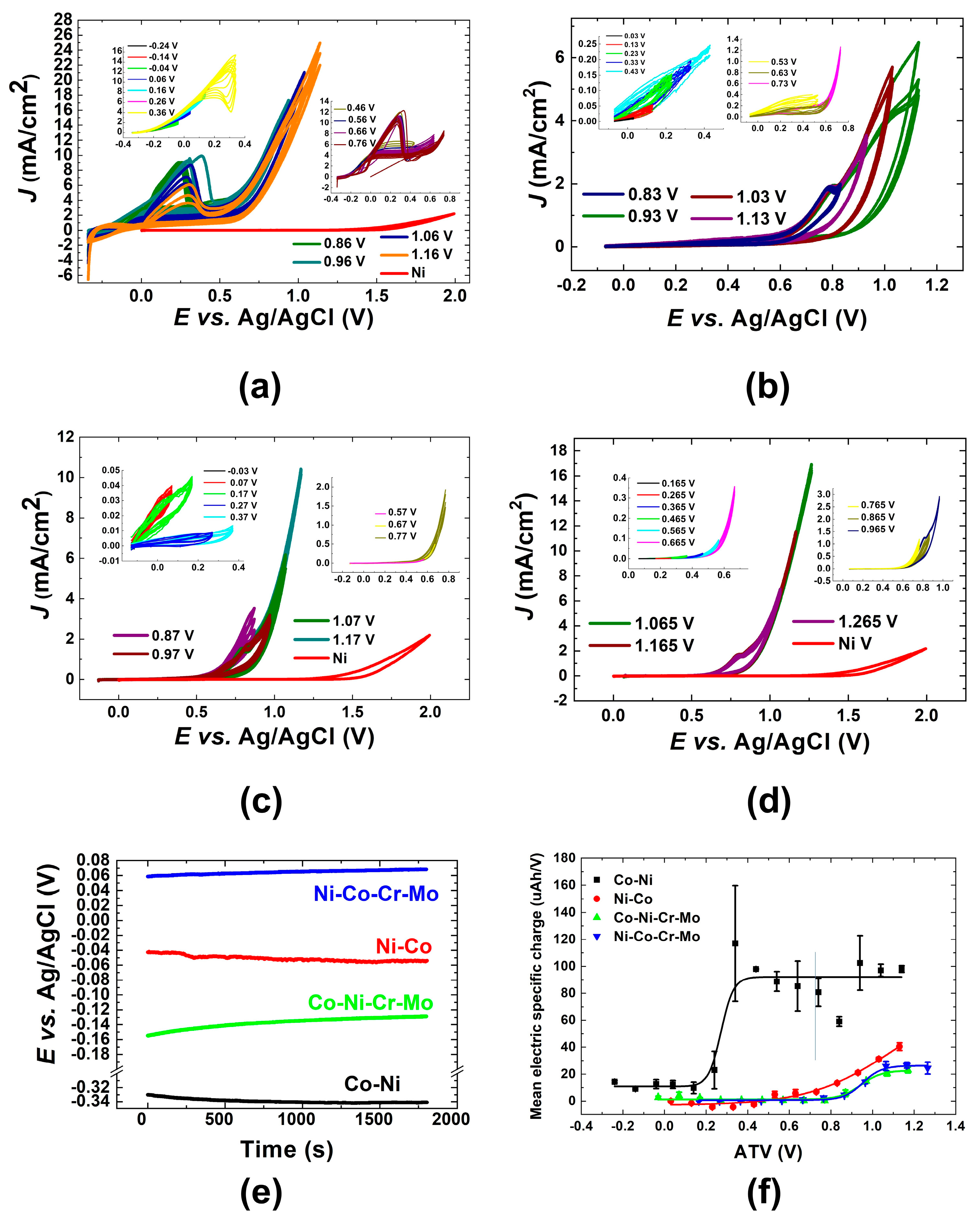
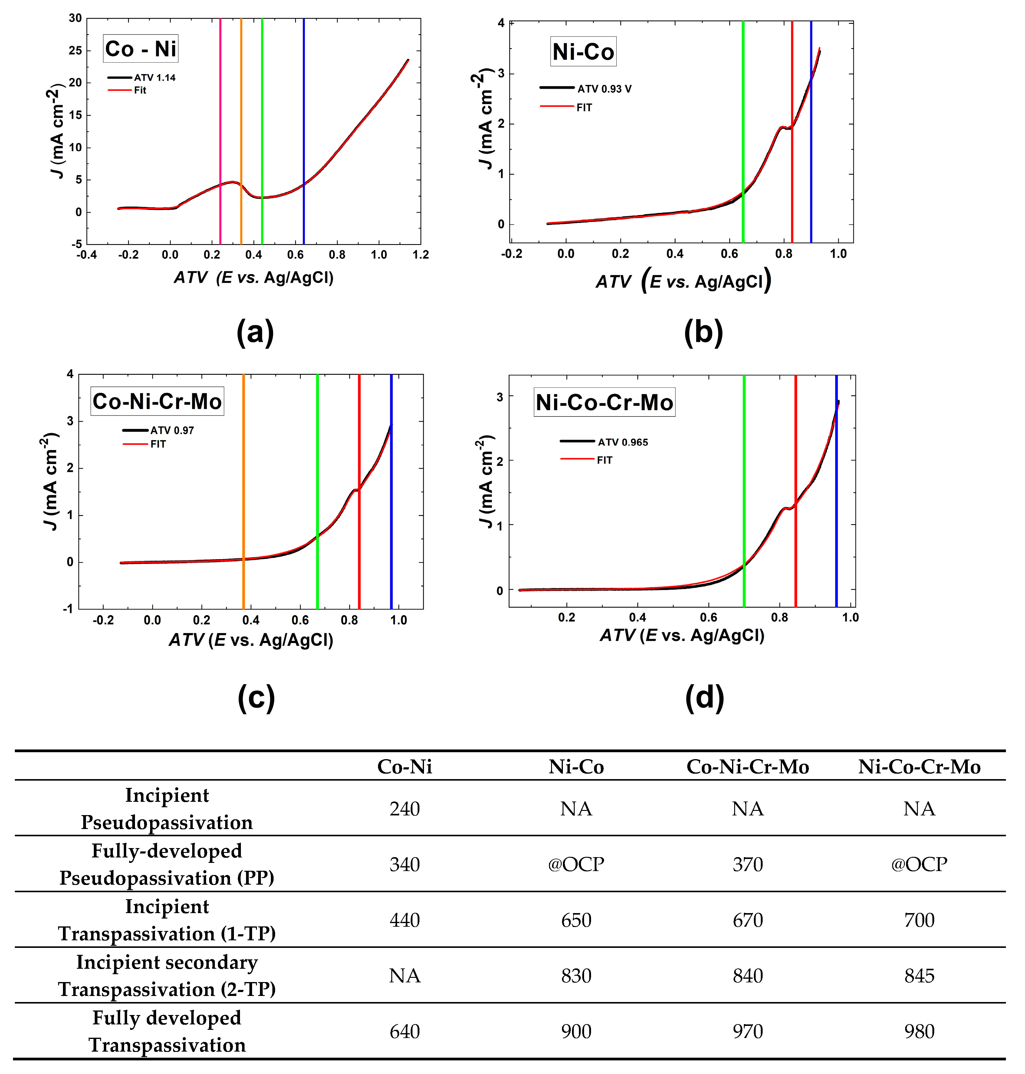
3.1. Sequential CV with Variation of the Anodic Terminal Voltage (ATV)

The corrosion of HM grades is an intrinsically transient-state process, whereby, in principle, phase modification and phase formation processes take place simultaneously, leading to a complex scenario of cumulative chemical and structural changes and irreversibilities. More details on these irreversibilities and on the way they affect electrochemical measurements are provided in Section S1 of the Supplementary Material. In the context of the present research, we thus endeavored to develop an approach, based on simple electrochemical measurements, that can systematically account for progressive changes in material composition and composite structure.
For the reasons expounded above, as hinted at in Section 2.1, we have carried out sequences of CV tests (Figure 1a–d) with the CTV set at the OCP value (Figure 1e) and increasing the ATV in steps of 100 mV, until transpassive conditions are attained. This approach allowed the identification of the Ecrit values at which irreversibilities in the electrochemical behavior develop. Specific measurements carried out at the thus identified Ecrit and characterization of grades treated at these potentials—described in the following—enabled us to disclose the key classes of HM modifications brought about by corrosion. In Panels (a–d), for calibration purposes, we also report a CV measured at a Ni foil electrode. Thanks to the high OER electrocatalytic activity of Ni, this measurement allows us to distinguish OER from transpassive corrosion for the investigated HM grades.
Coherently with literature findings [67,68], the OCP time-series of Figure 1e exhibit a denobling trend for the Co-rich samples (Co-Ni and Ni-Co) and progressive ennobling for the Ni-rich ones (Co-Ni-Cr-Mo and Ni-Co-Cr-Mo). The CVs of grade Co-Ni (Figure 1a) exhibit an active corrosion range, followed by an evident pseudopassivation feature that is typical of Co-rich grades [69,70], while the other grades (Panels (b–d)) have achieved the pseudopassivated state under environmental exposure.
To gain a more quantitative grasp of the evolution of electrochemical irreversibility, the CVs of Figure 1a–d have been integrated in order to evaluate the dependence of the consumed charge on the number of cycles and on the ATV. The essential information is summarized in Figure 1f, in which we report the mean charge per cycle as a function of the ATV and details are reported in Figure S1 in the Supplementary Material. This analysis highlights that the dependence of the anodic charge on the ATV (Figure 1f and Figure S1a,c,e,g) in the Supplementary Material exhibits a monotonically increasing tendency, with an abrupt rise, followed by an approximately constant level, corresponding to the completion of the pseudopassivation peak for grade Co-Ni and of the inception of the transpassive range for the other grades. In addition, the variation of the anodic charge with the number of cycles (Figure S1b,d,f,h) in the Supplementary Material grows until pseudopassivation (for Co-Ni) or transpassivity (for the remaining grades) is reached.
From the CVs of Figure 1a–d and the analysis of the exchanged charge (Figure 1f and Figure S1 in the Supplementary Material), evident characteristic differences of corrosion behavior and corrosion-induced irreversibility emerge among grades. These can be straightforwardly ranked on the basis of: (i) the current densities attained at a given potential and (ii) the transpassive potential values. Firstly, the Co-rich HMs (Co-Ni and Co-Ni-Cr-Mo) are much less resistant than the Ni-rich ones (Ni-Co, Ni-Co-Cr-Mo) and addition of Cr + Mo (Co-Ni-Cr-Mo and Ni-Co-Cr-Mo) enhances dramatically the corrosion resistance of both grades. This quantitative outcome is coherent with the literature on the corrosion-resistance enhancement of grades with these additives [43,44,65,66,71]. The voltammetric behavior of the Cr + Mo containing Co-rich grade (Co-Ni-Cr-Mo) is similar to that of the Ni-rich (Ni-Co) one without binder additives.
Focusing on the details of the CVs of Figure 1a–d—in combination with the evolution of the anodic charge with ATV and number of cycles, analyzed in Figure S1 in the Supplementary Material—it can be noticed that there are classes of the CV pattern group in specific potential ranges, as detailed in Figures S2–S5 in the Supplementary Material. Specifically, one can distinguish four classes for grades Co-Ni and Co-Ni-Cr-Mo and three for Ni-Co-Cr-Mo, as described below.
In grade Co-Ni, class (a) corresponds to active dissolution; here, progressive cycling brings about an increase in c.d., corresponding to an increase in active area. Class (b) is the incipient passivation range and repeated cycling clearly shows a decrease in c.d., denoting growth of the pseudopassivation film. Class (c) corresponds to fully developed pseudopassivation and repeated cycling still shows a systematic decrease in c.d., as in class (b). Finally, class (d) corresponds to the transpassive range.
In grade Ni-Co, class (a), though essentially corresponding to a pseudopassive state, nevertheless exhibits some aspects of active corrosion: (i) higher c.d. in the cathodic-going scan and (ii) progressive c.d. increase by increasing the ATV and with cycling. Class (b) corresponds to incipient passivation. Class (c) corresponds to the transpassive range, with the peculiarity of showing a secondary pseudopassivation process, bringing about a small but well-defined and perfectly reproducible c.d. maximum. Finally, transpassive behavior is resumed for the c.d. maximum (class (d)).
In grade Co-Ni-Cr-Mo, class (a) exhibits the typical features of progressive passivation: (i) c.d. decreases with increasing ATV; (ii) lower c.d. in the cathodic-going scan and (iii) progressive (though limited) c.d. reduction upon cycling. Classes (b–d) are the same as in grade Ni-Co.
In grade Ni-Co-Cr-Mo, class (a) exhibits the characteristics of fully passivated state, while classes (b), (c) and (d), like in grades Ni-Co and Co-Ni-Cr-Mo, correspond to incipient transpassivity, secondary pseudopassivation and fully developed transpassivity, respectively.
The classes described in the previous paragraph identify four Ecrit values, corresponding to qualitative changes in electrochemical response: incipient pseudopassivity, fully developed pseudopassivity, incipient transpassivity (without further specification for grade Co-Ni, primary transpassivity for grades Ni-Co, Co-Ni-Cr-Mo and Ni-Co-Cr-Mo), incipient secondary transpassivity (for grades Ni-Co, Co-Ni-Cr-Mo and Ni-Co-Cr-Mo) and fully developed transpassivity; this information is summarized in Figure 2. Moreover, to further the quantitative analysis of the CV curves and of their classes of electrochemical behavior, the above-expounded classes of electrochemical behavior can be fitted with a general phenomenological model, expressing the key corrosion processes presented, implemented and discussed in Section S2 of the Supplementary Material.

3.2. Characterization of HM Grades Polarized Electrochemically at the Critical Potentials Ecrit

On the basis of the classification of the corrosion behavior of the investigated HM grades proposed in Section 3.1, we have carried out an in-depth analysis of the evolution of the HM behavior, centered on potentiostatic measurements, electrochemical impedance spectrometry (EIS), SEM, EDS analysis and UV–Vis reflectance spectroscopy, that will be expounded in the present section. The combination of these measurements enables a thorough mechanistic understanding of the irreversible evolution of the surface and subsurface chemistry and structure brought about by HM corrosion.
The rationale of this analysis is that of investigating the HM performance and properties, referring to conditions selected from the ones listed in Figure 2 and specified below, that are more promising in view of achieving complete electrochemical dissolution of HM scrap. In the case of the Co-rich grades (Co-Ni and Co-Ni-Cr-Mo)—for which both pseudopassivity and transpassivity can be controlled electrochemically—the pseudopassive (Co-Ni: incipient and fully developed pseudopassivity; Co-Ni-Cr-Mo: fully developed pseudopassivity) and traspassive (Co-Ni: incipient and fully developed transpassivity; Co-Ni-Cr-Mo: incipient primary transpassivity and fully developed secondary transpassivity) regimes are found. For the Ni-rich grades (Ni-Co and Ni-Co-Cr-Mo), that achieve the pseudopassive state by ambient exposure, the incipient secondary transpassivity is found. For ease of reference, the selected Ecrit values have been highlighted with a box in Figure 2.

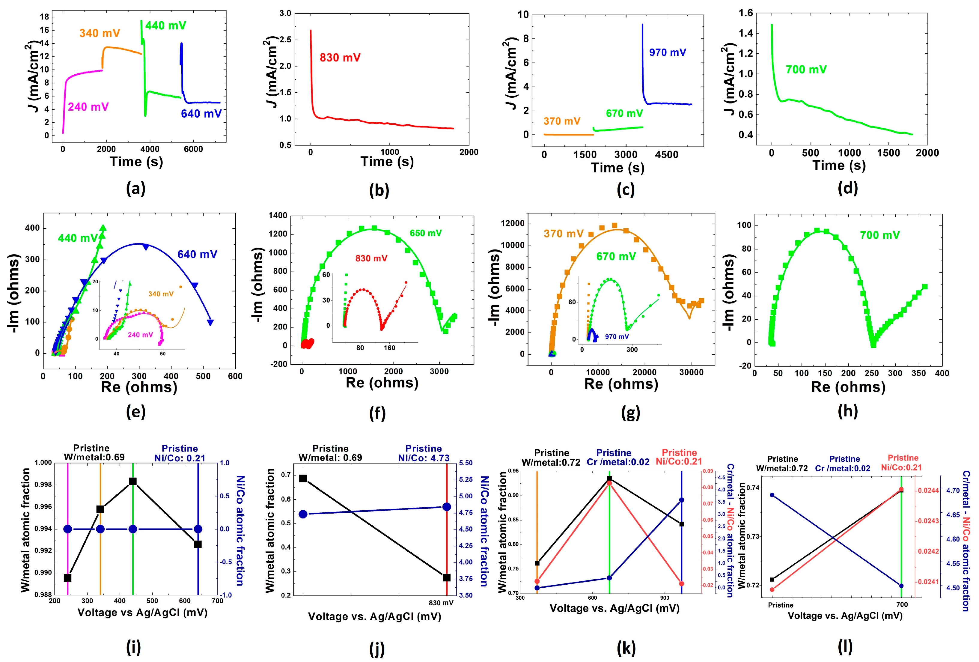
3.2.1. Potentiostatic (PS) Measurements

Figure 3a reports the results of the potentiostatic tests. Three classes of time dependence can be noticed. (i) In the active range of Co-Ni (purple plot) and in the pseudopassive range of Co-Ni-Cr-Mo before primary transpassivity (orange and green plots), the c.d. tends to increase, denoting an increase in the active area. (ii) In the incipient passivation or secondary transpassivity conditions (orange and green plots for grade Co-Ni and the chronoamperograms of grades Ni-Co and Ni-Co-Cr-Mo), the c.d. decreases, indicating the progressive surface depletion of active material and/or the build-up of layers inhibiting the corrosion process. (iii) In the fully developed transpassive range (Co-Ni, blue plot; Co-Ni-Cr-Mo, blue plot), the c.d. is essentially constant, showing the achievement of steady-state corrosion conditions.

3.2.2. Electrochemical Impedance Spectrometry (EIS) Measurements

The characterization of the electrochemical behavior of the four grades investigated at Ecrit was completed by EIS measurements, carried out both under applied bias (Figure 3b) and at OCP after the potentiostatic test (Figure S7b).
In general, the data can be modeled with an RC loop at high frequencies followed by a Warburg impedance at low frequencies. The infinite diffusion-length equation is adequate for the investigated frequency range. A few exceptions—found in high-c.d. cases of the measurements carried out under applied potential—require additional components: (i) an RL loop at low frequencies, denoting electrodic adsorption of electroactive intermediates (Figure 3b (Co-Ni at 240 mV, Co-Ni-Cr-Mo at 970 mV)) [72]; (ii) two RC loops (Figure 3b (Co-Ni 240 mV)). The NLLS parameters are reported in Table 3.
EIS spectra measured under applied polarization at Ecrit, reported in Figure 3c, reveal a scenario that is notably richer than the one that can be achieved on the basis of potentiostatic tests (Figure 3a) and EIS measurements carried out at OCP, both in pristine conditions and after having applied PS conditions at Ecrit (Section S3 of the Supplementary Material). In the case of the most reactive grade Co-Ni, with high-Co and no Cr-Mo, exhibiting the lowest corrosion resistance and free corrosion in the active range (240 mV), incipient (340 mV) and developed pseudopassivation (440 mV) as well as reactivation upon incipient transpassivity (640 mV) correlate evidently with the CV pattern, denoting a relatively higher propensity for active corrosion. The Ni-rich grade Ni-Co shows an evident increase in RF with respect to the Co-richer grade Co-Ni; inception of primary and secondary transpassivity shows an active corrosion process, accompanied by weak mass-transport control signature. This EIS response correlates with an improved corrosion resistance, correlating with the Ni content.
Grade Co-Ni-Cr-Mo clearly shows an impact of Cr + Mo addition, in terms of increased RF, together with the tendency, typical of Co-richer grades, towards progressive activation by increasing the anodic polarization into the primary and secondary transpassive ranges. In terms of corrosion resistance, this corresponds to a lower resistance under mildly oxidizing conditions, with respect to Ni-Co, but a notably improved resistance under highly anodic polarizations. Reactivation of the surface upon attainment of secondary transpassive conditions is witnessed in the low-frequency inductive loop found at 960 mV. The measurement of grade Ni-Co-Cr-Mo under incipient secondary transpassive conditions shows a behavior which is very similar to that of grades Ni-Co and Co-Ni-Cr-Mo, pointing towards the role of Ni and Cr-Mo in the establishment of secondary transpassivity. A higher Ni content ensures high corrosion resistance in weakly oxidizing ambients, while that of Cr and Mo imparts notable protection against strongly oxidizing conditions. In conjunction, EIS at OCP (Section S3 of the Supplementary Material) and under PS control (Figure 3c) reveals the following factors of HM corrosion. (i) Grades with binders containing Cr + Mo exhibit relatively active transpassive behavior, that, nevertheless, after relaxation at OCP, leaves behind an ennobled, passivated surface. Ni content evidently imparts better passive properties. (ii) EIS under bias allows correlation of secondary transpassivity with the presence of Ni and/or Cr, with Cr increasing the RF at incipient secondary transpassivity. (iii) In more reactive high-Co grades, PS polarization gives rise to an activity imprinting, whereby the hierarchy of corrosion activity, assessed by EIS with applied potential, correlates with the activity at OCP of the resulting surface conditions. Instead, in the high-Ni grades, no activity imprinting was found.

3.2.3. EDS Compositional Analyses

EDS analysis carried out on HM grades subjected to PS corrosion at Ecrit is reported in Figure 3c. The evidently better corrosion resistance of the grades containing Cr + Mo can be straightforwardly related to the fact that pseudopassive conditions correspond to the formation of a Cr- and W-enriched surface layer that is instead oxidized at transpassive potentials. These changes in surface composition are more limited in the best-performing grade Ni-Co-Cr-Mo, with a high Ni/Co ratio. The Ni-rich grade Ni-Co, in the absence of Cr + Mo additions, shows denobling under incipient primary transpassivity, related to a decrease in surface W in the presence of active corrosion of the binder, as witnessed by the fact that the Ni/Co ratio is essentially the same as that of the pristine sample. The Co-rich grade Co-Ni shows denobling in active conditions and progressive ennobling upon driving the anodic potential into the pseudopassive and incipient transpassive ranges (see also Figure S7a in the Supplementary Material). Initial denobling is due to the preferential leaching of Ni and progressive ennobling to the leaching of the binder, leaving behind a W-enriched surface enriched in Ni. In the transpassive range (point at 640 mV), W starts to be effectively leached, and the surface fraction of Co increases slightly. It is worth noting that in the Co-rich sample Co-Ni-Cr-Mo, the addition of Cr + Mo correlates with a notable surface enrichment in Ni that increases with the anodic potential in the investigated range.

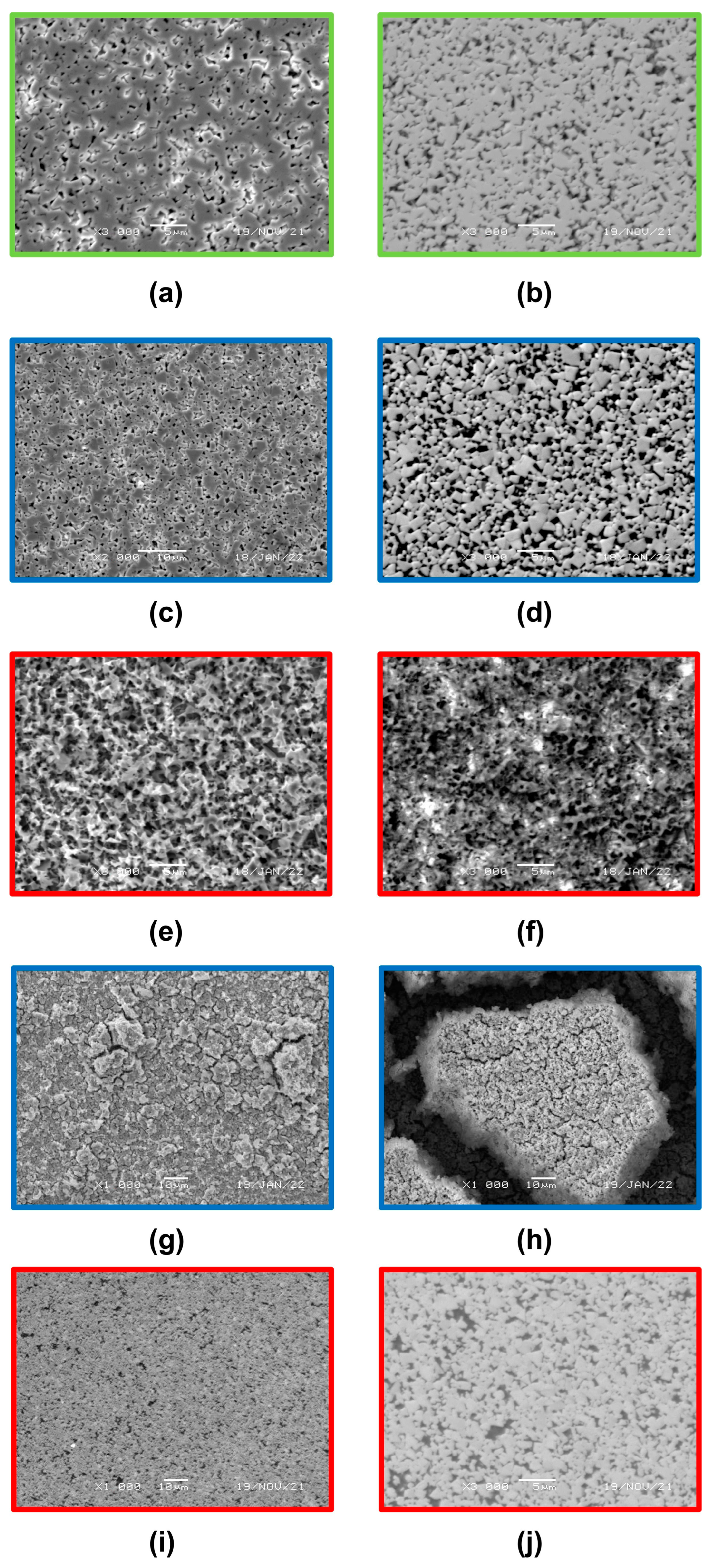
3.2.4. Scanning Electron Microscopy

The investigation of the surface transformation of HMs polarized at the Ecrit values was completed with SEM observations. To better chacaterize the scenario and for reference, some tests were also carried out at additional potentials, as detailed where relevant. A representative selection of micrographs is reported in Figure 4 and the systematic microscopic documentation is available in Figures S8–S10 of the Supplementary Material. By comparing secondary electron (SE) and backscattered electron (BSE) images, it is possible to discriminate between the surfacemost layer of corrosion products and the subsurface composite structure. Figure S8 shows the results of the tests carried out with grade Co-Ni. Two comments are in order here. Firstly, even though a steady state can indeed be obtained, as pinpointed in Section 3.1 and Section 3.2.1, the corrosion morphology of hardmetals is a strictly time-dependent observable and, in principle, the pseudopassivation and passivation films and the transpassive surface structure change with aggression time under otherwise identical conditions. We shall discuss the specific corrosion morphology corresponding to the attack conditions relevant to the demolition investigation. A systematic study of time-dependent corrosion morphology would be an independent investigation in its own right. Secondly, as a result of both the time dependence mentioned above and the formation of complex thick corrosion product films, the corrosion morphology of hardmetal surfaces cannot be straightforwardly classified in terms of the classical corrosion types commonly referred to in the literature. By comparing SE and BSE images, one can clearly notice the presence of a porous, uniform surface layer that correlates clearly with pseudopassivity (Panels (a) and (b) of Figure 4). The pore positions correspond to the binder regions.
The morphological scenario revealed by SE is essentially the same in the whole investigated potential range, encompassing active corrosion (Figure S8a: 240 mV), incipient pseudopassivation (340 mV, images essentially the same as for 240 mV; not reported for brevity), fully developed pseudopassivity (Figure 4a and Figure S8c: 440 mV) and incipient transpassivity (Figure 4c and Figure S8e: 640 mV). The BSE images instead show some notable differences in the morphology of the W-rich framework. In the active and incipient pseudopassive ranges (240–340 mV, Figure S8b), the intact WC grain structure, resulting from binder dissolution, can be clearly appreciated. Pseudopassive conditions (440 mV, Figure 4d and Figure S8d) show less well-defined W-rich areas that can be explained with the attack of WC; this leads to partial loss of the original polygonal WC morphology and to the spreading of a W-enriched oxidized phase in the regions initially occupied by the binder.
A similar scenario is found with grade Ni-Co under pseudopassive conditions (Figure S9a,b: 650 mV), with the key difference that the surface film detected by BSE is not a porous one as with grade Co-Ni but rather it shows a pattern corresponding to the original WC grain structure. This morphology relates to the less actively corroding Ni-rich binder, resulting in a corrosion product film free of pinholes. Under incipient secondary transpassivity conditions (Figure 4e,f and Figure S9c,d: 830 mV), the corrosion morphology is totally different: the surface film is no longer visible and the WC grains are extensively corroded, giving way to a porous surface, characterized by micrometric pits. Instead, under the same incipient secondary transpassivity conditions, addition of Cr + Mo to the Ni-rich binder (Figure 4i,j and Figure S9e,f: 845 mV) results in the preservation of the surfacemost film, with the formation of micrometric porosities, under which the W-rich grainy structure is not disrupted.
Addition of Cr + Mo to the Co-rich binder of grade Co-Ni-Cr-Mo (Figure S10a,b and Figure S10c,d, corresponding to 370 and 670 mV, respectively) yields the same sequence of morphologies found with grade Ni-Co. Pushing the anodic potential in the full secondary traspassive range (Figure 4g,h and Figure S10e,f: 960 mV), the pitted morphology gives way to one that is typical of electrochemical oxide growth, with a homogeneous distribution of crystallites and a well-developed micrometric cracking pattern.

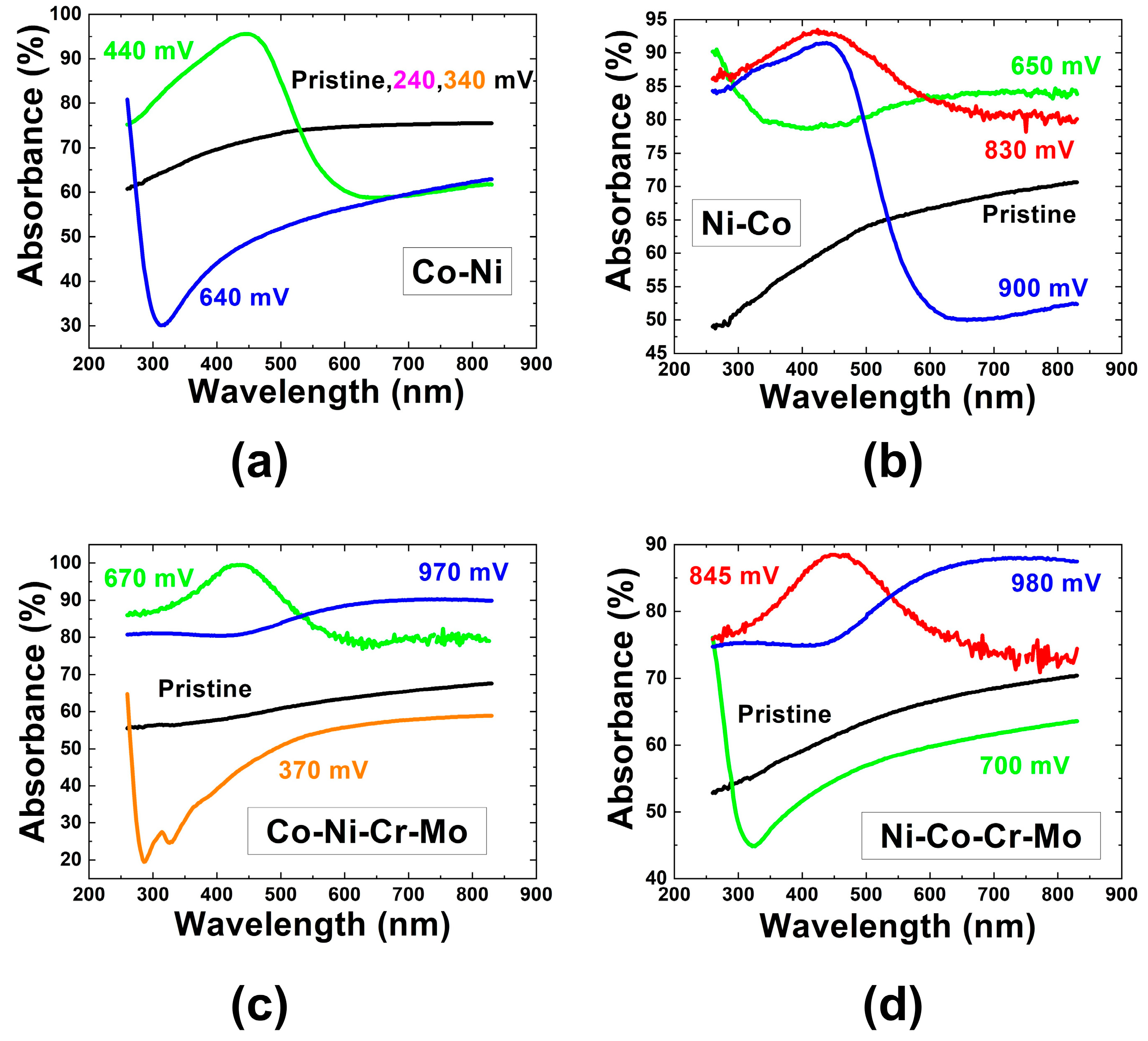
3.2.5. UV–Vis Reflectance Spectroscopy

UV–Vis reflectance spectroscopy is sensitive to the electronic structure of compounds and allows us to discriminate between metallic and oxidized species and to distinguish different types of oxides and hydroxides [27,73,74,75,76]. This approach—which is reported here for the first time in the case of hardmetal corrosion studies—can thus be fruitfully employed to achieve a deeper physico-chemical understanding of the nature of pseudopassive layers. Of course, this method is intrinsically sensitive to the topmost material layers and cannot disclose information regarding the interface between the corrosion layer and the residual uncorroded bulk, but this limitation does not impair the additional information that can be gleaned for the purpose of the present study. Figure 5 reports the UV–Vis specular reflectance spectra of the surface of the investigated samples in a pristine state and after PS corrosion in the conditions of Figure 3a. It can be noticed that the reflectivity of pristine samples is dominated by WC (WC-type spectra [77]), with the binder adding a slight white-metal-type contribution. In less corrosion-resistant Co-Ni, WC-type reflectivity (Figure 5a) is also found in the whole active corrosion range—with minor differences, not highlighted for brevity—since binder dissolution impacts negligibly the dominant contribution of the ceramic phase. The reflectivity in the pseudopassive range of Co-Ni (Figure 5a) is controlled by a spectral pattern essentially corresponding to WO3, possibly with metal-ion doping and/or some degree of nanostructuring [78]. The optical response of Co-Ni in the transpassive range (Figure 5a) is typical of TMyWO4 compounds [79,80,81], coherent with the SEM analyses which revealed the attack of both binder and WC in this potential range.
The spectral patterns of more corrosion-resistant grades Ni-Co, Co-Ni-Cr-Mo and Ni-Co-Cr-Mo (Panels (b–d) of Figure 5, respectively) exhibit notable common aspects. (i) A pseudopassive state achieved by environmental exposure: these grades spontaneously develop a pseudopassive layer exhibiting the TMyWO4-type optical response—with slight differences depending on the binder composition—showing that the surface films observed by SEM consist of oxidation products containing both binder elements and W. (ii) Incipient transpassivity is characterized by the WO3-type spectral pattern, indicating that the increase in c.d. is dominated by WC corrosion. (iii) Corrosion in the fully developed transpassive range is different in grades without (Ni-Co, Figure 5b) and with (Co-Ni-Cr-Mo, Figure 5c and Ni-Co-Cr-Mo, Figure 5d) Cr + Mo additions. Grade Ni-Co exhibits an optical response that is very similar to that observed under incipient transpassive conditions, while grades Co-Ni-Cr-Mo and Ni-Co-Cr-Mo exhibit a modified spectral pattern of the TMyWO4 class, that—according to the literature—might be related to W-based mixed oxides with more than one additional metallic element [82,83,84]. This kind of optical behavior suggests that in grade Ni-Co the surface is strongly binder depleted and is thus dominated by WC corrosion, while in grades Co-Ni-Cr-Mo and Ni-Co-Cr-Mo the binder still contributes to the formation of a mixed oxide that imparts higher corrosion protection.

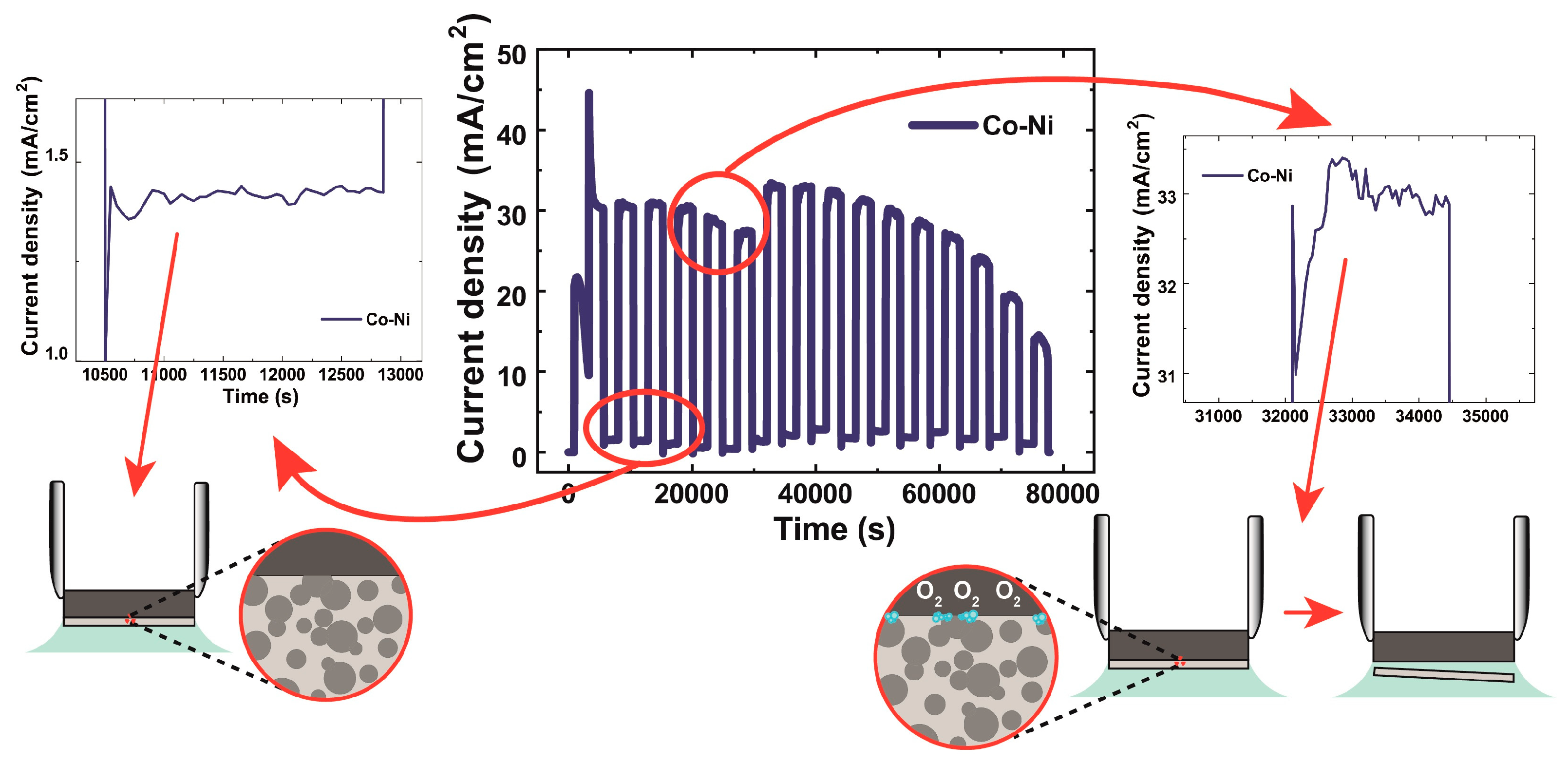
3.3. Electrochemical Demolition of HM Grades

From the literature summarized in the Introduction, as well as from industrial experience, it is empirically evident that galvanostatic and potentiostatic polarization of hardmetals, aimed at the electrochemical demolition of scrap for the recovery of the constituent elements, is indeed feasible, but with the key drawback that the corrosion current slowly tends to converge to zero, owing to so far poorly understood pseudopassivation processes. This leads to practically unacceptable recovery rates or to the need for alternating periods of electrochemical attack and of mechanical treatment, aimed at removing the pseudopassive layers, thus regaining electrochemical activity. This solution, though in principle viable, is expensive and impractical.
In line with these facts, the conclusions of Section 3.2 provide the mechanistic insight into the nature of the corrosion process and of the corrosion product layers, on the basis of which one can exclude the possibility of attaining electrochemical corrosion rates compatible with industrial requirements. In fact, the global message is that, at low anodic polarizations, relatively stable pseudopassive films form, while in the fully transpassive range active corrosion of both binder and WC can be obtained, but with c.d. values that would not enable industrially dissolution rates. Moving still more anodically and fully into the oxygen evolution range does not change the dissolution efficiency. The fact that corrosion product films formed at highly anodic potentials from different HM grades, though of different composition, are stable over time and do not give way to faster dissolution modes is clearly shown by potentiostatic experiments extending into the OER range (Figure S11 of the Supplementary Material).
Overall, this scenario confirms that electrochemical corrosion alone (i.e., dissolution) does not seem to enable high-rate destruction of HM scrap, confirming that mechanical action of some kind (i.e., demolition) is needed. Nevertheless, the appropriate mechanical action can indeed be obtained by electrochemical polarization alone. In fact, by applying anodic polarization in the pseudopassive or early transpassive ranges, as shown in Section 3.2, a range of films can form, consisting of the combination of partly corroded binder and WC, with their specific nature strongly depending on the grade and polarization history. Notwithstanding their profound differences, these films share two key properties: they are poorly electronically conducting and porous. This means that the observed limited residual electrochemical activity of corroded HM samples is localized at the metallic HM structure screened by the corrosion product layer. Thus, if after the formation of a layer of appropriate thickness and porosity, the potential is switched to the OER range, O2 bubbles can be nucleated at the interface between the subsurface residual electroactive region of the HM and the insulating film that can detach the pseudopassive layer, on the one hand carrying out the progressive demolition of the HM sample and, on the other hand, reactivating electrochemically the sample towards the formation of a subsequent corrosion product layer, as schematized in Figure 6. Thus, switching between film formation and OER-induced film detachment regimes can result in effective, entirely electrochemically driven, HM demolition. The top panel of Figure 6 shows a typical c.d. response to the PS square-wave cycles in which periodic detachment of pseudopassive film layers can be achieved for grade Co-Ni. The accompanying schematic illustrates conceptually an HM demolition cycle, including: (a) the formation of corrosion product film, (b) followed by O2 evolution, (c) leading to film detachment. The complete information for the four grades considered in this study is reported in Figure S12 and further described in Section S4 of the Supplementary Material. Electrochemical switching from pseudopassivation to OER leads to the sequential detachment of corrosion product disks, that is documented in the bottom panel of Figure 6 and in the time-lapse movie that can be downloaded from the journal website.
All investigated grades can be electrochemically demolished with this approach, but some interesting differences emerge in the behavior of specific HMs. Firstly, all grades except Co-Ni, that exhibits a higher propensity to active corrosion, show a progressive c.d. increase in the low-anodic branch (left-hand side of Figure S12e) that shows, on the one hand, corrosion activation after the OER period (c.d. increase during each potentiostatic holding interval) and, on the other hand, progressive roughening (c.d. increase over a series of cycles). The c.d. response in each potentiostatic holding period at high anodic values (right-hand side of Figure S12e), again with the exception of grade Co-Ni that exhibits an essentially constant value, shows a tendency to decrease. Specifically, grade Ni-Co shows an initial spike that reaches levels matching those found in the galvanostatic staircase, followed by a period in which the c.d. relaxes to a notably lower value, with a slight tendency to increase. This rich electrochemical dynamic scenario, and its dependence on the different grade chemistries, requires further investigation that is the object of ongoing fundamental study.
The metal composition of the disks detached during electrochemical demolition was analyzed by EDS and found to consist essentially of W, with small amounts of residual binder metals (Table 4). Moreover, the oxygen content—as measured by IR spectrometry—was found to be 26.4 ± 1.0 atomic %. These data indicate that the detached disks basically consist of WO3, indicating good selectivity of the process towards the separation of W and binder elements.
Finally, the kinetics of HM demolition by the anodic potential switching method was evaluated by weight change measurements of the treated samples. The results span between about 5 mm/y, for the grade Ni-Co, and 50 mm/y, for the grade Co-Ni, demonstrating that the demolition rate is at least two orders of magnitude higher than the corrosion rates in potentiostatic conditions and similar environments, reported in the literature to be of the order of 0.050 mm/y in traditional electrochemical recovery approaches [26,85]. It is worth noting that even the grades with higher corrosion resistance can be effectively demolished with the electrochemical process described here.

4. Conclusions

This work proposes a novel sustainable and low-cost method for the destruction of HM scrap, preliminary to the recovery of raw materials. Our approach, that is electrochemical in nature, employs a neutral aqueous electrolyte and operates at room temperature and can replace the thermal oxidation processes that are in current use. Past attempts to follow the electrochemical route failed owing to extremely low dissolution rates that led to the necessity of adding mechanical steps to the process (corrosion/grinding approach) that made it impractical and expensive. The success of our approach is due to the fact that high destruction rates are achieved by obtaining the required mechanical action with mere electrochemical control, hence the new denomination “electrochemical demolition”. The discovery of this process was enabled by the in-depth understanding of the electrochemical details disclosed in this study. In fact, on the basis of systematic electrochemical investigations, combined with morphochemical studies of the corrosion product layers, we have definitively proved that the holy grail sought after by the electrochemical HM destruction approach—i.e., high dissolution rate obtained by the selection of optimal electrochemical polarization conditions—is simply impossible to attain.
More specifically, a common aspect of HM corrosion processes emerging from our multi-technique study, carried out in a vast range of electrochemical conditions, is that the rich scenario of selective corrosion of binder and carbide and film formation including both pseudopassive and transpassive processes leads in any case to very low corrosion rates. At low polarization, preferential binder corrosion dominates the anodic behavior, but pseudopassive film formation and field confinement due to the regress of the binder surface in the gap among WC grains progressively decreases the corrosion rate. At high polarizations, WC corrosion is the controlling factor, but its rate is slow owing to local acidification resulting from the release of transition metal ions in the electrolyte, in turn leading to stabilization of insoluble tungsten oxides, as well as to the formation of W-, Ni- and Co-containing mixed oxides.
Thus, in-depth understanding of the corrosion process and of the nature of corrosion product layers opened up the possibility of carrying out targeted electrochemistry that could achieve precisely the required mechanical action to destroy the layers inhibiting free corrosion. In fact, pseudopassive conditions lead to the formation of a corrosion product layer, the porosity and/or ionic conductivity of which can in principle be tuned, supported on the electronically conducting subsurface structure, consisting of WC grains and residual binder. In this scenario, the formation of a pseudopassive layer, followed by polarization in the OER range, can lead to the build-up of O2 pressure at the interface between the pseudopassive film and the electroactive subsurface layer that detaches the pseudopassive film and reactivates the sample. Thus, a pulsed potentiostatic anodic process, periodically switching between the pseudopassive and the OER ranges, ensures sustained, fully electrochemical HM demolition by periodic release of corrosion product foils. This common behavior, though with material-dependent peculiarities, was found for all grades investigated. Moreover, the electrochemical demolition process proposed exhibits the additional advantage of a high chemical selectivity: the detached solid fraction consists of essentially pure W, while Co and Ni are released to the electrolyte. Of course, the thermal or conventional corrosion/grinding yield destruction processes in which W, Co and Ni are mixed.
This work presents a comprehensive and fully self-contained study of a novel aqueous electrochemical method for the high-rate, corrosion-based destruction of hardmetal scrap with an energetically mild and environmentally benign approach, liable to change the scenario of hardmetal recovery. This process opens up a sustainable route for hardmetal recycling, competing with the currently energy-demanding and polluting thermal approach, characterized by a large carbon footprint and a high consumption of natural gas. Electrochemical recovery has been explored for decades, but—notwithstanding a relatively extensive literature—no industrially viable process has been identified so far, owing to the extremely low throughput allowed by this approach, caused by hardmetal passivation. Our systematic study of the fundamentals of hardmetal passivation enabled the discovery of an original way to use electrochemistry to achieve a productivity increase of at least two orders of magnitude with respect to traditional electrochemical demolition approaches, fully compatible with industrial requirements and liable to open up a concrete industrial route for the recovery of CRMs from HM scrap. Future work will target a more systematic investigation of the parameter space of the pulsed anodic process and materials science studies of the released corrosion product foils and their post-processing towards final Co, W and Ni recovery.

Supplementary Materials

The following supporting information can be downloaded at: https://www.mdpi.com/article/10.3390/met13081376/s1, Figure S1: Quantitative analyses of the CVs of Figure 1a–d for the grades indicated in the panels. (a, c, e, g) Specific charge per cycle (rationed over the voltage span of a given CV), as a function of the number of cycles, for a given anodic terminal voltage (ATV, color-coded as shown in the image). (b, d, f, h) Specific charge per cycle vs. ATV, averaged over all cycles measured with a given ATV (an extract of these data is reported in Figure 1f). For ease of reference, the ATVs are color-coded in each panel. (a) Co-Ni, (b) Ni-Co, (c) Co-Ni-Cr-Mo, (d) Ni-Co-Cr-Mo; Figure S2: Grouping in classes of voltammetric shapes for the CVs measured by progressively shifting the anodic terminal voltage (ATV) with grade Co-Ni; Figure S3: Grouping in classes of voltammetric shapes for the CVs measured by progressively shifting the anodic terminal voltage (ATV) with grade Ni-Co; Figure S4: Grouping in classes of voltammetric shapes for the CVs measured by progressively shifting the anodic terminal voltage (ATV) with grade Co-Ni-Cr-Mo; Figure S5: Grouping in classes of voltammetric shapes for the CVs measured by progressively shifting the anodic terminal voltage (ATV) with grade Ni-Co-Cr-Mo; Figure S6: Fit parameters for Eq. (S1) (see also Panel (a)), as a function of the ATV. (b) iP1 for grade Co-Ni; (c) io1; (d) V1; (e) B1; (f) ip; Figure S7: (a) OCP measurements carried out after the potentiostatic tests at the critical potentials Ecrit reported in Figure 3a. (b) EIS spectra measured at OCP in pristine conditions and after the OCP relaxation of Panel (a); Figure S8: SEM micrographs of HM grade Co-Ni after potentiostatic polarization at the indicated potentials. Left column: secondary electron images; right column: backscattered electron images; Figure S9: SEM micrographs of HM grades Ni-Co and Ni-Co-Cr-Mo after potentiostatic polarization at the indicated potentials. Left column: secondary electron images; right column: backscattered electron images; Figure S10: SEM micrographs of HM grade Co-Ni-Cr-Mo after potentiostatic polarization at the indicated potentials. Left column: secondary electron images; right column: backscattered electron images; Figure S11: Anodic potentiostatic experiments extending into the OER region for the indicated HM grades. (a) Current density (c.d.) vs. time; (b) c.d. vs. applied potential; (c) chronoamperograms at 1.55 VAg/AgCl. Serration of the c.d. time-series at potentials in excess of 1.55 VAg/AgCl denotes O2 bubble formation and release; Figure S12: The c.d. time-series resulting from potentiostatic anodic square-wave cycling, leading to electrochemical HM demolition, for the four investigated grades: (a) grade Co-Ni; (b) grade Ni-Co; (c) grade Co-Ni-Cr-Mo; (d) grade Ni-Co-Cr-Mo. The low- and high-anodic potentials, specified in the images, are applied for 40 min each. Panel (e) compares the four time-series and shows details of the c.d. response to low- and high-anodic potentials; Figure S13: Details of the c.d. time-series resulting from pulsed anodic potentiostatic polarization for electrochemical HM demolition of grades Co-Ni (a) and Ni-Co-Cr-Mo (b), highlighting the electrochemical signature corresponding to the detachment of a corrosion product disk at each cycle; Figure S14: Comparison of the c.d. values corresponding to potentiostatic polarization in the low-anodic range: potential cycling (black lines) and constant potential (plotted in color) experiments for the HM grades are indicated; Table S1: NLLS estimates and their 95% confidence levels for the model parameters of Eqs. (S1.1)–(S1.4).

Author Contributions

Conceptualization, B.B. and G.P.D.G.; Methodology, B.B., F.T., A.T., C.M. and G.P.D.G.; Validation, B.B., F.T., A.T., A.A., C.M., E.E., S.T. and G.P.D.G.; Formal analysis, B.B., F.T., A.T., C.M. and G.P.D.G.; Investigation, B.B., F.T., A.T., A.A., C.M., E.E., S.T. and G.P.D.G.; Data curation, F.T., A.T., C.M. and S.T.; Writing—original draft, B.B., F.T. and A.T.; Writing—review and editing, B.B., F.T., A.T., A.A., C.M., E.E., S.T. and G.P.D.G.; Visualization, B.B., F.T., A.T., A.A., C.M., E.E., S.T. and G.P.D.G.; Supervision, B.B. and G.P.D.G. All authors have read and agreed to the published version of the manuscript.

Funding

This study was carried out within the MOST—Sustainable Mobility Center and received funding from the European Union Next-GenerationEU (PIANO NAZIONALE DI RIPRESA E RESILIENZA (PNRR)—MISSIONE 4 COMPONENTE 2, INVESTIMENTO 1.4—D.D. 1033 17/06/2022, CN00000023). This manuscript reflects only the authors’ views and opinions, neither the European Union nor the European Commission can be considered responsible for them.

Data Availability Statement

The raw data required to reproduce these findings will be made available by the authors, upon reasonable request.

Conflicts of Interest

The authors declare no conflict of interest.

References

  1. Garcia, J.; Collado Ciprés, V.; Blomqvist, A.; Kaplan, B. Cemented carbide microstructures: A review. Int. J. Refract. Met. Hard Mater. 2019, 80, 40–68. [Google Scholar] [CrossRef]
  2. Konyashin, I. Approaching the 100th anniversary of the Hardmetal invention: From first WC-Co samples towards modern advanced Hardmetal grades. Int. J. Refract. Met. Hard Mater. 2023, 111, 106113. [Google Scholar] [CrossRef]
  3. Kurlov, A.S.; Gusev, A.I. Tungsten Carbides: Structure, Properties and Application in Hardmetals. Springer Ser. Mater. Sci. 2013, 184, 34–36. [Google Scholar] [CrossRef]
  4. Konyashin, I.; Ries, B. Cemented Carbides; Elsevier Inc.: Amsterdam, NL, USA, 2022; ISBN 9780128228203. [Google Scholar]
  5. Šubić, J.; Slokar Benić, L.; Selanec, M.; Erman, Ž. Effect of Hard Metal Production on the Environment. Holist. Approach Environ. 2022, 12, 102–109. [Google Scholar] [CrossRef]
  6. European Commission. Study on the Critical Raw Materials for the EU 2023—Final Report, DG GROW; European Commission: Bruxelles, Belgium, 2023. [CrossRef]
  7. Zeiler, B.; Bartl, A.; Schubert, W.-D. Recycling of Tungsten: Current Share, Economic Limitations, Technologies and Future Potential. Int. J. Refract. Met. Hard Mater. 2021, 98, 105546. [Google Scholar] [CrossRef]
  8. Altuncu, E.; Ustel, F.; Türk, A.; Ozturk, S.; Erdoğan, G. Cutting-Tool Recycling Process with the Zinc-Melt Method for Obtaining Thermal-Spray Feedstock Powder (WC-Co). Mater. Tehnol. 2013, 47, 115–118. [Google Scholar]
  9. Barnard, P.G.; Kenworthy, H. Reclamation of Refractory Carbides from Carbide Materials. U.S. Patent 3,595,484A, 27 July 1971. [Google Scholar]
  10. Joost, R.; Pirso, J.; Viljus, M. Recycling of hardmetal scrap to W, Co powder by oxidation reduction process. In Proceedings of the 6th International DAAAM Baltic Conference Industrial Engineering, Tallinn, Estonia, 24–26 April 2008; pp. 24–56. [Google Scholar]
  11. Katiyar, P.K.; Randhawa, N.S. A comprehensive review on recycling methods for cemented tungsten carbide scraps high-lighting the electrochemical techniques. Int. J. Refract. Met. Hard Mater. 2020, 90, 105251. [Google Scholar] [CrossRef]
  12. Walraedt, J. Proceedings of 7th International Plansee Seminar. Metallwerk Plansee, Reutte, Austria, 1971; Volume IV(2), p. 1.
  13. Kieffer, B.F. Proceedings of International Tungsten Symposium—Tungsten. San Francisco, CA, USA, 1982; p. 102.
  14. Pacini, A.; Lupi, F.; Rossi, A.; Seggiani, M.; Lanzetta, M. Direct Recycling of WC-Co Grinding Chip. Materials 2023, 16, 1347. [Google Scholar] [CrossRef]
  15. Jonsson, K.A. Process for Chlorination of Material Containing. Hard Metal. U.S. Patent 3,560,199, 2 February 1971. [Google Scholar]
  16. Takahashi, T.R.; Yuize, T. Method of Chemically Disintegrating and Pulverizing Sold Material. U.S. Patent 2,848,313, 19 August 1958. [Google Scholar]
  17. Kojima, T.; Shimizu, T.; Sasai, R.; Itoh, H. Recycling Process of WC-Co Cermets by Hydrothermal Treatment. J. Mater. Sci. 2005, 40, 5167–5172. [Google Scholar] [CrossRef]
  18. Cera, M.; Trudu, S.; Oumarou Amadou, A.; Asunis, F.; Farru, G.; De Gaudenzi, G.P.; De Gioannis, G.; Serpe, A. Trends and perspectives in the use of organic acids for critical metal recycling from hard-metal scraps. Int. J. Refract. Met. Hard Mater. 2023, 114, 106249. [Google Scholar] [CrossRef]
  19. Oumarou Amadou, A.; Cera, M.; Trudu, S.; Piredda, M.; Cara, S.; De Gaudenzi, G.P.; Singh Matharu, A.; Marchiò, L.; Tegon, M.; Muntoni, A.; et al. A comparison among bio-derived acids as selective eco-friendly leaching agents for cobalt: The case study of hard-metal waste enhancement. Front. Environ. Chem. 2023, 4, 1216245. [Google Scholar] [CrossRef]
  20. Srivastava, R.R.; Kim, M.-S.; Kim, M.-S.; Lee, J.-C.; Jha, M.K.; Kim, B.-S. Resource recycling of superalloys and hydrometallurgical challenges. J. Mater. Sci. 2014, 49, 4671–4686. [Google Scholar] [CrossRef]
  21. Srivastava, R.R.; Lee, J.-C.; Bae, M.; Kumar, V. Reclamation of tungsten from carbide scraps and spent materials. J. Mater. Sci. 2019, 54, 83–107. [Google Scholar] [CrossRef]
  22. Furberg, A.; Arvidsson, R.; Molander, S. Environmental life cycle assessment of cemented carbide (WC-Co) production. J. Clean. Prod. 2019, 209, 1126–1138. [Google Scholar] [CrossRef]
  23. Aromaa, R.; Rinne, M.; Lundström, M. Comparative Life Cycle Assessment of Hardmetal Chemical Recycling Routes. ACS Sustain. Chem. Eng. 2022, 10, 10234–10242. [Google Scholar] [CrossRef]
  24. Sutthiruangwong, S.; Mori, G.; Kösters, R. Passivity and Pseudopassivity of Cemented Carbides. Int. J. Refract. Met. Hard Mater. 2005, 23, 129–136. [Google Scholar] [CrossRef]
  25. Hochstrasser-Kurz, S.; Reiss, D.; Suter, T.; Latkoczy, C.; Günther, D.; Virtanen, S.; Uggowitzer, P.; Schmutz, P. ICP-MS, SKPFM, XPS, and Microcapillary Investigation of the Local Corrosion Mechanisms of WC-Co Hardmetal. J. Electrochem. Soc. 2008, 155, C415–C426. [Google Scholar] [CrossRef]
  26. Tarragó, J.M.; Fargas, G.; Jiménez-Piqué, E.; Felip, A.; Isern, L.; Coureaux, D.; Roa, J.; Al-Dawery, I.; Fair, J.; Llanes, L. Corrosion Damage in WC-Co Cemented Carbides: Residual Strength Assessment and 3D FIB-FESEM Tomography Characterisation. Powder Metall. 2014, 57, 324–330. [Google Scholar] [CrossRef]
  27. Bozzini, B.; Busson, B.; De Gaudenzi, G.P.; Humbert, C.; Mele, C.; Tedeschi, S.; Tadjeddine, A. Corrosion of Cemented Carbide Grades in Petrochemical Slurries. Part I—Electrochemical Adsorption of CN¯, SCN¯ and MBT: A Study Based on in Situ SFG. Int. J. Refract. Met. Hard Mater. 2016, 60, 37–51. [Google Scholar] [CrossRef]
  28. Zhang, L.; Chen, Y.; Wan, Q.; Liu, T.; Zhu, J.; Tian, W. Electrochemical Corrosion Behaviors of Straight WC–Co Alloys: Exclusive Variation in Grain Sizes and Aggressive Media. Int. J. Refract. Met. Hard Mater. 2016, 57, 70–77. [Google Scholar] [CrossRef]
  29. Tang, W.; Zhang, L.; Chen, Y.; Zhang, H.; Zhou, L. Corrosion and Strength Degradation Behaviors of Binderless WC Material and WC–Co Hardmetal in Alkaline Solution: A Comparative Investigation. Int. J. Refract. Met. Hard Mater. 2017, 68, 1–8. [Google Scholar] [CrossRef]
  30. De Gaudenzi, G.P.; Tavola, F.; Tedeschi, S.; Bozzini, B. Corrosion Behaviour of Cemented Carbides with Co- and Ni-Alloy Binders in the Presence of Abrasion. Metals 2022, 12, 1914. [Google Scholar] [CrossRef]
  31. Jayaraj, J.; Elo, R.; Babu Surreddi, K.; Olsson, M. Electrochemical and passivation behavior of a corrosion-resistant WC-Ni(W) cemented carbide in synthetic mine water. Int. J. Refract. Met. Hard Mater. 2023, 114, 106227. [Google Scholar] [CrossRef]
  32. Pereira, P.; Ferro Rocha, A.M.; Bastos, A.C.; Oliveira, F.J.; Vilhena, L.M.; Ramalho, A.; Sacramento, J.; Malheiros, L.F.; Senos, A.M.R. Development of WC-NiCrMo hardmetals. Int. J. Refract. Met. Hard Mater. 2023, 112, 106147. [Google Scholar] [CrossRef]
  33. Pan, Z.; Luo, H.; Zhao, Q.; Cheng, H.; Wang, X.; Ma, Y.; Li, X. Novel Mo-modified medium entropy alloys achieving enhanced corrosion resistance in acidic solution. Corr. Sci. 2023, 216, 111094. [Google Scholar] [CrossRef]
  34. Alves Nery Balbino, N.; Otoni Corrêa, E.; Roque Huanca, D.; Amaury de Freitas Matos, F.; de Carvalho Valeriano, L. Comparative Study of Corrosion Behaviors of WC-NiMo and WC-Co Cemented Carbides. Materials 2023, 16, 4480. [Google Scholar] [CrossRef]
  35. Pereira, P.; Vilhena, L.; Sacramento, J.; Senos, A.; Malheiros, L.; Ramalho, A. Influence of Different Binders and Severe Environmental Conditions on the Tribological and Electrochemical Behaviour of WC-Based Composites. Lubricants 2022, 10, 145. [Google Scholar] [CrossRef]
  36. Aleksandrov Fabijanić, T.; Šnajdar, M.; Kurtela, M.; Šimunović, V.; Marciuš, M.; Klaić, M. Corrosion Resistance of Nanostructured Cemented Carbides with Alternative FeNi and FeNiCo Binders. Nanomaterials 2023, 13, 1407. [Google Scholar] [CrossRef]
  37. Pötschke, J.; Vornberger, A.; Gestrich, T.; Berger, L.-M.; Michaelis, A. Influence of different binder metals in high entropy carbide based hardmetals. Powder Metall. 2022, 65, 373–381. [Google Scholar] [CrossRef]
  38. Tang, T.; Xiao, X.; Xu, K.; Lou, M.; Hu, X.; Li, S.; Zhang, W.; Fan, Z.; Chang, K. Corrosion-resistant WC-Co based cemented carbides: Computational design and experimental verification. Int. J. Refract. Met. Hard Mater. 2023, 110, 106044. [Google Scholar] [CrossRef]
  39. Qian, C.; Cheng, H.; Li, K.; Liu, Y.; Zhang, S.; Zhang, J. Corrosion behavior of functionally graded cemented carbides with CoNiCrFe binder. Corr. Sci. 2023, 222, 111383. [Google Scholar] [CrossRef]
  40. Alar, Ž.; Alar, V.; Fabijanić, T.A. Electrochemical Corrosion Behavior of Near-Nano and Nanostructured WC-Co Cemented Carbides. Metals 2017, 7, 69. [Google Scholar] [CrossRef] [Green Version]
  41. Bozzini, B.; Gianoncelli, A.; Kourousias, G.; Boniardi, M.; Casaroli, A.; Dal Zilio, S.; Hussain, R.; Abyaneh, M.K.; Kiskinova, M.; Mele, C.; et al. The Role of Chromium in the Corrosion Performance of Cobalt- and Cobalt-Nickel Based Hardmetal Binders: A Study Centred on X-Ray Absorption Microspectroscopy. Int. J. Refract. Met. Hard Mater. 2020, 92, 105320. [Google Scholar] [CrossRef]
  42. Katiyar, P.K.; Randhawa, N.S.; Hait, J.; Jana, R.K.; Singh, K.K.; Mankhand, T.R. Anodic dissolution behaviour of tungsten carbide scraps in ammoniacal media. Adv. Mat. Res. 2014, 828, 11–20. [Google Scholar] [CrossRef]
  43. Steinlechner, R.; de Oro Calderon, R.; Koch, T.; Linhardt, P.; Schubert, W.D. A Study on WC-Ni Cemented Carbides: Constitution, Alloy Compositions and Properties, Including Corrosion Behaviour. Int. J. Refract. Met. Hard Mater. 2022, 103, 105750. [Google Scholar] [CrossRef]
  44. Santos, R.; Rocha, A.; Bastos, A.C.; Cardoso, J.P.; Rodrigues, F.; Fernandes, C.M.; Sacramento, J.; Ferreira, M.; Senos, A.M.R.; Fonseca, C.; et al. Microstructural Characterization and Corrosion Resistance of WC-Ni-Cr-Mo Composite—The Effect of Mo. Int. J. Refract. Met. Hard Mater. 2019, 86, 105090. [Google Scholar] [CrossRef]
  45. Ghandehari, M.H.; Faulkner, J.K.; Schussler, M. Selective Dissolution of the Binder Phase Alloy (Co-W) from WC-Co Cemented Carbides in Particulate Bed Electrode Systems. J. Electrochem. Soc. 1982, 129, 2666. [Google Scholar] [CrossRef]
  46. Madhavi Latha, T.; Venkatachalam, S. Electrolytic Recovery of Tungsten and Cobalt from Tungsten Carbide Scrap. Hydrometallurgy 1989, 22, 353–361. [Google Scholar] [CrossRef]
  47. Lin, J.C.; Lin, J.Y.; Lee, S.L. Process for Recovering Tungsten Carbide from Cemented Tungsten Carbide Scraps by Selective Electrolysis. U.S. Patent 5,384,016, 24 January 1995. [Google Scholar]
  48. Paul, R.L.; Te Riele, W.A.M.; Nicol, M.J. A Novel Process for Recycling Tungsten Carbide Scrap. Int. J. Miner. Process. 1985, 15, 41–56. [Google Scholar] [CrossRef]
  49. Malyshev, V.V.; Hab, A.I. Separation of Cobalt and Tungsten Carbide by Anodic Dissolution of Solid Alloys in Phosphoric Acid. Mater. Sci. 2004, 40, 555–559. [Google Scholar] [CrossRef]
  50. Niitzel, H.G. Process for Decomposing Hard Metal Scrap. U.S. Patent 4,349,423, 14 September 1982. [Google Scholar]
  51. Kuntyi, O.I.; Yavorskyi, V.T.; Ivashkiv, V.R.; Kaminskii, R.M.; Saldan, I.V. Four-factor optimization for electrochemical conversion of WC-Ni pseudo alloy in sulfuric acid solutions. Chem. Eng. Commun. 2012, 199, 838–848. [Google Scholar] [CrossRef]
  52. Malyshev, V.V.; Gab, A.I. Resource-Saving Methods for Recycling Waste Tungsten Carbide-Cobalt Cermets and Extraction of Tungsten from Tungsten Concentrates. Theor. Found. Chem. Eng. 2007, 41, 436–441. [Google Scholar] [CrossRef]
  53. Ghandehari, M.H. Process for Recovering Metal Carbide Powder from Cemented Carbides. U.S. Patent 4,234,333, 18 November 1980. [Google Scholar]
  54. Zaichenko, V.N.; Fomanyuk, S.S.; Krasnov, Y.S.; Kolbasov, G.Y. Recovery of Tungsten and Cobalt from Secondary Raw Materials by a Combined Electrochemical and Chemical Procedure. Russ. J. Appl. Chem. 2010, 83, 1660–1662. [Google Scholar] [CrossRef]
  55. Kobayakawa, Y. Method of Recovering the Component Metals from Sintered Metal Carbides. U.S. Patent 4,140,597, 20 February 1979. [Google Scholar]
  56. Hairunnisha, S.; Sendil, G.K.; Rethinaraj, J.P.; Srinivasan, G.N.; Adaikkalam, P.; Kulandaisamy, S. Studies on the Preparation of Pure Ammonium Para Tungstate from Tungsten Alloy Scrap. Hydrometallurgy 2007, 85, 67–71. [Google Scholar] [CrossRef]
  57. Tuvić, T.; Pašti, I.; Mentus, S. Tungsten Electrochemistry in Alkaline Solutions—Anodic Dissolution and Oxygen Reduction Reaction. Russ. J. Phys. Chem. A 2011, 85, 2399–2405. [Google Scholar] [CrossRef]
  58. Srinivasan, G.N.; Varadharaj, A.; Abdul Kader, J.A.M. Anodic Leaching of Tungsten Alloy Swarf: A Statistical Approach. J. Appl. Electrochem. 1994, 24, 1191–1193. [Google Scholar] [CrossRef]
  59. Vanderpool, C.D.; Tai, T.K. Electrolytic Method for Producing Ammonium Paratungstate from Cemented Tungsten Carbide. U.S. Patent 5,021,133, 4 June 1991. [Google Scholar]
  60. Vanderpool, C.D. Electrolytic Disintegration of Sintered Metal Carbides. U.S. Patent 4,385,972, 31 May 1983. [Google Scholar]
  61. Davidod, A.D.; Shaldaev, V.S.; Malofeeva, A.N.; Savotin, I.V. Electrochemical Dissolution of Tungsten under Pulsed Conditions. J. Appl. Electrochem. 1997, 27, 351–354. [Google Scholar] [CrossRef]
  62. Randhawa, N.; Katiyar, P. Potentiodynamic Polarization Behavior and Microscopic Examination of Tungsten Carbide Hard Metal Materials in Supported Ammoniacal Medium. Port. Electrochimica Acta 2020, 38, 185–200. [Google Scholar] [CrossRef]
  63. Lin, J.-C.; Lin, J.-Y.; Jou, S.-P. Selective Dissolution of the Cobalt Binder from Scraps of Cemented Tungsten Carbide in Acids Containing Additives. Hydrometallurgy 1996, 43, 47–61. [Google Scholar] [CrossRef]
  64. FILMS, S.p.A. Innovativo processo elettrochimico a ridotto impatto ambientale finalizzato al recupero di carburo di tungsteno da rottame di metallo duro, Final Report, Legge 27/10/1994 N. 598—D.g.r. n.63-13094/2004- Regione Piemonte, Intervento agevolativo a sostegno di progetti di ricerca industriale e sviluppo precompetitivo presentati da PMI.
  65. De Gaudenzi, G.P.; Garabelli, M.; Rossi, F.; Tedeschi, S.; Bozzini, B. The Corrosion Effects on CoNi-Base Hardmetals with Different Co:Ni Ratios and Additives in Simulated Service Conditions. In Proceedings of the Proc. EURO PM2021, Online Event, 18–22 October 2021. EP215066954, EPMA. [Google Scholar]
  66. De Gaudenzi, G.P.; Garabelli, M.; Rossi, F.; Tedeschi, S.; Bozzini, B. The Role of Molybdenum as an Additive in Hardmetal Metallic Binder Alloys. In Proceedings of the EURO PM2020, Virtual Congress, 5–7 October 2020. EP2004850238, EPMA. [Google Scholar]
  67. Pereira, P.; Rocha, A.M.F.; Sacramento, J.; Oliveira, F.J.; Senos, A.M.R.; Malheiros, L.F.; Bastos, A.C. Corrosion Resistance of WC Hardmetals with Different Co and Ni-Based Binders. Int. J. Refract. Met. Hard Mater. 2022, 104, 105799. [Google Scholar] [CrossRef]
  68. Zheng, Y.F.; Fargas, G.; Lavigne, O.; Roitero, E.; Llanes, L. Corrosion-Induced Changes on Hertzian Contact Damage in Cemented Carbides. Int. J. Refract. Met. Hard Mater. 2020, 92, 105334. [Google Scholar] [CrossRef]
  69. Zhang, X.; Zhou, J.; Liu, C.; Li, K.; Shen, W.; Lin, Z.; Li, Z.; He, Y.; Lin, N. Effects of Ni Addition on Mechanical Properties and Corrosion Behaviors of Coarse-Grained WC-10(Co, Ni) Cemented Carbides. Int. J. Refract. Met. Hard Mater. 2019, 80, 123–129. [Google Scholar] [CrossRef]
  70. De Gaudenzi, G.P.; Bozzini, B. Meccanismi di Corrosione del Metallo Duro. Metl. Itall 2017, 11/12, 39–48. Available online: http://www.aimnet.it/la_metallurgia_italiana/2017/nov_dic/bozzini.pdf (accessed on 15 January 2021).
  71. Santos, R.F.; Rocha, A.M.F.; Bastos, A.C.; Cardoso, J.P.; Rodrigues, F.; Fernandes, C.M.; Sacramento, J.; Ferreira, M.G.S.; Senos, A.M.R.; Fonseca, C.; et al. The Effect of Cr Content on the Corrosion Resistance of WC-Ni-Cr-Mo Composites. Int. J. Refract. Met. Hard Mater. 2021, 95, 105434. [Google Scholar] [CrossRef]
  72. Mansfeld, F.; Lorenz, W.J. Electrochemical Impedance Spectroscopy (EIS): Application in Corrosion Science and Technology. In Techniques for Characterization of Electrodes and Electrochemical Processes; Sarma, R., Selman, J.R., Eds.; John and Wiley and Sons: Hoboken, NJ, USA, 1991; pp. 605–614. [Google Scholar] [CrossRef] [Green Version]
  73. De Gaudenzi, G.P.; Grigioni, I.; Mele, C.; Tedeschi, S.; Bozzini, B. Electrochemical Studies on the Behaviour of WC-Co Hardmetal as a Function of Cobalt Content and Environmental pH. In Proceedings of the Proc. EURO PM2017, Milano, Italy, 1–5 October 2017. EP1703685851, EPMA. [Google Scholar]
  74. Borrás, C.A.; Romagnoli, R.; Lezna, R.O. In-Situ Spectroelectrochemistry (UV–Visible and Infrared) of Anodic Films on Iron in Neutral Phosphate Solutions. Electrochim. Acta 2000, 45, 1717–1725. [Google Scholar] [CrossRef]
  75. Yang, J.; Blawert, C.; Lamaka, S.V.; Yasakau, K.A.; Wang, L.; Laipple, D.; Schieda, M.; Di, S.; Zheludkevich, M.L. Corrosion Inhibition of Pure Mg Containing a High Level of Iron Impurity in PH Neutral NaCl Solution. Corros. Sci. 2018, 142, 222–237. [Google Scholar] [CrossRef]
  76. Fan, C.; Shi, J.; Sharafeev, A.; Lemmens, P.; Dilger, K. Optical Spectroscopic and Electrochemical Characterization of Oxide Films on a Ferritic Stainless Steel. Mater. Corros. 2020, 71, 440–450. [Google Scholar] [CrossRef] [Green Version]
  77. Huang, W.; Meng, H.; Gao, Y.; Wang, J.; Yang, C.; Liu, D.; Liu, J.; Guo, C.; Yang, B.; Cao, W. Metallic Tungsten Carbide Nanoparticles as a Near-Infrared-Driven Photocatalyst. J. Mater. Chem. A 2019, 7, 18538–18546. [Google Scholar] [CrossRef]
  78. Yoshimizu, M.; Hotori, Y.; Irie, H. Ohmic Hetero-Junction of n-Type Silicon and Tungsten Trioxide for Visible-Light Sensitive Photocatalyst. J. Mater. Sci. Chem. Eng. 2017, 05, 33–43. [Google Scholar] [CrossRef] [Green Version]
  79. Paul Chowdhury, A.; Shambharkar, B.H. Synthesis and Photocatalytic Properties of Sunlight-Responsive BiOBr–CoWO4 Heterostructured Nanocomposites. Appl. Organomet. Chem. 2020, 34, e5436. [Google Scholar] [CrossRef]
  80. Shin, J.; Do, J.Y.; Kim, R.; Son, N.; Park, N.-K.; Ryu, H.-J.; Seo, M.W.; Chi, J.; Youn, Y.-S.; Kang, M. Catalytic Activity of Ni1-XLi2xWO4 Particles for Carbon Dioxide Photoreduction. Catalysts 2019, 9, 467. [Google Scholar] [CrossRef] [Green Version]
  81. Li, C.; Diao, P. Boosting the Activity and Stability of Copper Tungsten Nanoflakes toward Solar Water Oxidation by Iridium-Cobalt Phosphates Modification. Catalysts 2020, 10, 913. [Google Scholar] [CrossRef]
  82. He, T.; Yao, J. Photochromic Materials Based on Tungsten Oxide. J. Mater. Chem. 2007, 17, 4547–4557. [Google Scholar] [CrossRef]
  83. Upadhyay, S.B.; Mishra, R.K.; Sahay, P.P. Cr-Doped WO3 Nanosheets: Structural, Optical and Formaldehyde Sensing Properties. Ceram. Int. 2016, 42, 15301–15310. [Google Scholar] [CrossRef]
  84. Parthibavarman, M.; Karthik, M.; Sathishkumar, P.; Poonguzhali, R. Rapid Synthesis of Novel Cr-Doped WO3 Nanorods: An Efficient Electrochemical and Photocatalytic Performance. J. Iran. Chem. Soc. 2018, 15, 1419–1430. [Google Scholar] [CrossRef]
  85. Bozzini, B.; De Gaudenzi, G.P.; Serra, M.; Fanigliulo, A.; Bogani, F. Corrosion Behaviour of WC-Co Based Hardmetal in Neutral Chloride and Acid Sulphate Media. Mater. Corros. 2002, 53, 328–334. [Google Scholar] [CrossRef]
Figure 1. Sets of CVs measured by progressively shifting the anodic terminal voltage (ATV) for grades: (a) Co-Ni; (b) Ni-Co; (c) Co-Ni-Cr-Mo; (d) Co-Ni-Cr-Mo. Electrolyte: aerated 0.2 M Na2SO4. Scan rate: 1 mV s−1. The CVs plotted with a thick red line were measured with a Ni foil electrode for calibration. (e) OCP time-series for pristine samples. (f) Specific charge per cycle vs. ATV, averaged on all cycles ±1 sdev, evaluated from the CVs of Panels (ad); for more details, see Figure S1 in the Supplementary Material.
Metals 13 01376 g001
Figure 2. Representative CVs, selected from the data reported in Figure 1a–d (anodic-going scans of the 10th cycle, fitted with the model presented in Section S2 of the Supplementary Material), to illustrate the classes of corrosion behavior of the investigated HM grades ((a) Co-Ni; (b) Ni-Co; (c) Co-Ni-Cr-Mo; (d) Ni-Co-Cr-Mo) and of the corresponding critical potentials Ecrit, highlighted with color-coded vertical bars. Incipient (pink) and fully developed transpassivation (blue) are conventionally set at 0.5 and 4 mA cm−2, respectively. Incipient 2-TP (red) is conventionally set after 1-TP (green) maximum. The Ecrit values selected for in-depth characterization (Section 3.2) are highlighted with a box. For more details, see Figures S2–S5 in the Supplementary Material.
Metals 13 01376 g002
Figure 3. (ad) Potentiostatic tests at the critical potentials Ecrit. (eh) EIS spectra measured under applied polarization at the Ecrit values of Panels (ad). (il) EDS measurements after the potentiostatic tests of Panels (ad). The measurements refer to the following HM grades: (a,e,i) Co-Ni, (b,f,j) Ni-Co, (c,g,k) Co-Ni-Cr-Mo and (d,h,l) Ni-Co-Cr-Mo. Ecrit. are represented by color coded-vertical bar: Incipient (pink); Fully developed pseudopassivation (orange); Incipient 1-TP (green); Incipient 2-TP (red); Fully developed transpassivation (blue).
Metals 13 01376 g003
Figure 4. SEM micrographs after potentiostatic polarization at Ecrit for the following HM grades and potentials: (a,b) Co-Ni 440 mV, (c,d) Co-Ni 640 mV, (e,f) Ni-Co 830 mV, (g,h) Co-Ni-Cr-Mo 970 mV, (i,j) Cr + Mo to the Ni-rich binder 845 mV. Left column: secondary electron images; right column: backscattered electron images. Ecrit. are represented by color coded Incipient 1-TP (green); Incipient 2-TP (red); Fully developed transpassivation (blue).
Metals 13 01376 g004
Figure 5. UV–Vis reflectance spectra of the surface of the indicated grades in pristine conditions and after potentiostatic corrosion at the indicated potentials. The measurements refer to the following HM grades: (a) Co-Ni, (b) Ni-Co, (c) Co-Ni-Cr-Mo and (d) Ni-Co-Cr-Mo.
Metals 13 01376 g005
Figure 6. Schematic of the electrochemical demolition process, based on potentiostatic cycles, first forming a porous corrosion product layer and then detaching it by O2 bubble formation. Top panel: c.d. time-series resulting from potentiostatic anodic square-wave cycling, leading to electrochemical HM demolition. The reported case refers to grade Co-Ni: see Figure S12 in the Supplementary Material for complete information on the four investigated grades. Bottom panel: frame sequence of disk detachment. Disks detached from previous loop are visible at the bottom of the beaker. The corresponding time-lapse movie is available from the journal website.
Metals 13 01376 g006
Table 1. Compositions of the investigated hardmetal grades.
Grade CodeCo
wt%
Ni
wt%
CrC2
wt%
Mo2C
wt%
WC
wt%
Co/Ni
wt% Ratio
Co-Ni9.902.1000884.714
Ni-Co2.109.9000880.212
Co-Ni-Cr-Mo8.401.800.900.90884.667
Co-Ni-Cr-Mo1.808.400.900.90880.214
Table 2. Mechanical, magnetic and structural properties of the investigated hardmetal grades.
Grade
Code
d
×103 kg m−3
HV30
(kg mm−2)
Hc
(A m−1)
MMS
%
TRS
(MPa)
Microporosity
Co-Ni14.331211 ± 167.08843734 ± 89A00B00C00
Ni-Co14.351124 ± 127.00773218 ± 38A00B00C00
Co-Ni-Cr-Mo14.281378 ± 127.24883825 ± 140A00B00C00
Co-Ni-Cr-Mo14.241275 ± 37.16913411 ± 72A00B00C00
Table 3. EIS fitting parameters for the spectra reported in Figure 3b and Figure S7b. RF,OCP (kΩ cm2), Ecrit (mVAg/AgCl); RF,PS (Ω cm2): Faradaic resistance; αOCP, αPS: CPE exponents; σOCP, σPS: Warburg parameter (Ω cm2 s−0.5): OCP and PS refer to measurements, respectively, at OCP and under applied potential. This grade is in the pseudopassive state under ambient conditions. • Coincides with OCP, for this grade. This potential refers to incipient primary transpassivity. This potential refers to incipient secondary transpassivity. ◦ Pooled from two RC loops (for reference, see Figure 3b, data referring to grade Co-Ni).
Co-NiNi-CoCo-Ni-Cr-MoNi-Co-Cr-Mo
Characteristic processEcrit/mVAg/AgCl
RF,OCP/kΩ cm2
αOCP
RF,PS/Ω cm2
αPS
Ecrit/mVAg/AgCl
RF,OCP/kΩ cm2
αOCP
RF,PS/Ω cm2
αPS
Ecrit/mVAg/AgCl
RF,OCP/kΩ cm2
αOCP
RF,PS/Ω cm2
αPS
Ecrit/mVAg/AgCl
RF,OCP/kΩ cm2
αOCP
RF,PS/Ω cm2
αPS
OCP−340
23.04 ± 0.12
0.92 ± 0.03
−60
36.85 ± 0. 43
0.76 ± 0.04
−130
307.5 ± 1.0
0.88 ± 0.01
70
399.2 ± 0.5
0.78 ± 0.02
σOCP = 27,397 ± 2102
Incipient
Pseudopassivation
240
2.12 ± 0.04
0.96 ± 0.08
17.59 ± 0.21 °
0.97 ± 0.03 °
N/A N/A N/A 
Fully-developed
Pseudopassivation (PP)
340
1.08 ± 0.02
0.83 ± 0.05
15.44 ± 2.343
0.77 ± 0.17
σPS = 39.48 ± 4.60
370
0.99 ± 0.04
98.8 ± 0.14
14730 ± 20
0.79 ± 0.02
σPS = 1853 ± 1924
Incipient
Transpassivation (1-TP)
440 
1.60 ± 0.12
0.65 ± 0.06
58.25 ± 7.79

σPS = 45.90 ± 17.85
830 
37.84 ± 0.21
0.77 ± 0.01
53.70 ± 11.03
0.82 ± 0.14
σPS = 12.78 ± 10.85
670 
129.2 ± 0.08
0.89 ± 0.03
135.4 ± 28.0
0.74 ± 0.22
σPS = 26.45 ± 27.28
845 
402.4 ± 3.7
0.86 ± 0.05
107.9 ± 0.3
0.98 ± 0.03
σOCP = 23,460 ± 19,399
σPS = 14.53 ± 15.75
Table 4. Wt% of binder metals found in the corrosion product disks, detached during the electrochemical demolition process. Balance is W.
GradeCo-NiNi-CoCo-Ni-Cr-MoNi-Co-Cr-Mo
Co0.19 ± 0.04 w%0.97 ± 0.13 w%0.88 ± 0.62 w%0.02 ± 0.02 w%
Ni4.18 ± 0.52 w%0.12 ± 0.16 w%0.32 ± 0.08 w%
Cr0.31 ± 0.01 w%
Mo1.43 ± 0.11 w%0.30 ± 0.15 w%
Disclaimer/Publisher’s Note: The statements, opinions and data contained in all publications are solely those of the individual author(s) and contributor(s) and not of MDPI and/or the editor(s). MDPI and/or the editor(s) disclaim responsibility for any injury to people or property resulting from any ideas, methods, instructions or products referred to in the content.

