Article

Effect of Increasing Oscillation Width on the Arc Characteristics and Droplet Transfer Behavior of X80 Steel in the Overhead Welding Position of Narrow Gap P-GMAW

School of Mechanical Engineering, Xinjiang University, Urumqi 830049, China
*
Author to whom correspondence should be addressed.
Metals 2023, 13(7), 1314; https://doi.org/10.3390/met13071314
Submission received: 2 July 2023 / Revised: 20 July 2023 / Accepted: 21 July 2023 / Published: 23 July 2023

Abstract

:
In the welding process of thick plate narrow gap pulse gas metal arc welding (P-GMAW) overhead welding station, the arc characteristics and droplet transfer behavior that become more complex due to the combined effects of narrow gap groove, gravity, and welding torch oscillation. The welding stability is more difficult to control. High-speed imaging and electrical signal acquisition systems were established to observe and record the arc behavior and droplet transfer during the welding process at different oscillation widths, further revealing the formation mechanism of welding seam in narrow gap P-GMAW overhead welding station. Research has found that with an increased oscillation width, the arc deflects towards the sidewall from a trumpet-shaped symmetrically distributed around the center of the groove at an increasing deflection angle, and the droplet transfer changes from one droplet per pulse to multiple droplets per pulse, resulting in defects such as lack of sidewall fusion and undercutting of the weld seam. Based on the welding process discussed in this study, it is recommended to use an oscillation width of 2.6 mm.

1. Introduction

Narrow gap welding, due to its requirement for narrow and deep grooves during the welding process, results in less filler metal consumption and higher welding efficiency [1,2,3]. As a result, it is widely used for joining thick-walled components in various fields such as oil and gas pipelines, pressure vessels, and other industries. The overhead welding process is unavoidable in the process of connecting these large thick-walled components because of their considerable size, intricate structure, and challenging positional adjustments [4,5,6]. When in the overhead welding station, there are difficulties in droplet transfer, reduced fluidity of the molten pool metal due to gravity, and a tendency for the molten metal to flow downward or even drip. This could result in welding defects such as lack of sidewall fusion, lack of interlayer fusion, and surface protrusions [7,8,9], significantly impacting the formation quality of the weld seam. Pulse gas metal arc welding (P-GMAW) has a wide range of adjustable welding parameters which can change the arc shape, control the droplet transfer, and effectively regulate the heat input to improve the performance of the welded joint. It is suitable for welding spatially positioned joints [10,11,12]. The arc morphology and droplet transfer behavior in the oscillating arc narrow gap P-GMAW welding process enhanced intricacy in the overhead station because of the effect of arc oscillation, narrow gap, and gravity, as compared to conventional welding.
Liu and Zhang et al. [13,14,15,16,17] studied the phenomenon of arc climbing during the welding process and further analyzed its influence on droplet transition behavior. Xu et al. [18,19,20] studied the effects of oscillation angle, oscillation speed, and sidewall dwell time of the narrow gap GMAW welding arc on the size of the upward welding seam. They established a statistical model for the geometric shape of the weld seam based on the response surface methodology. He et al. [21] studied the effects of welding current, arc voltage, and welding speed on sidewall penetration and surface concavity using the Taguchi method. They proposed that the main reason for the formation of incomplete fusion defects is that the surface tension of the molten pool is greatly affected by temperature and oxides, and arc oscillation is an effective measure to eliminate incomplete fusion defects on the sidewall. Zhu et al. [22] simulated the narrow gap oscillating arc GMAW process with CFD and studied the oscillating arc impact on the behavior of the welding pool. The results showed that a larger arc oscillation frequency and amplitude transfer more heat to the sidewalls, which can better promote sidewall fusion. Zhan et al. [23] conducted tests on the microstructure and mechanical properties of weld joints formed by oscillating arc welding and found no significant defects observed in the formed weld joints.
Chen and Xu et al. [24,25,26] researched the influence of spatial welding position on droplet transfer, mainly analyzing the influence of different spatial position changes on droplet transfer behavior. The research found the impact position of the molten droplets is mainly influenced by electromagnetic force and gravity. Cai and Wang et al. [27,28] discussed the impact of groove type [29] and groove gap on droplet transfer behavior during vertical upward welding of narrow gap GMAW and found that double compound angle grooves can obtain better full penetration weld specimens. As the gap increases, the droplet transfer mode of GMAW vertical upward welding develops from short circuit transfer to special droplet transfer. Wang et al. [30,31,32,33] studied rotating arc and optimized the welding device. Guo et al. [34,35,36,37,38] investigated the arc morphology and droplet transfer frequency during the horizontal and transverse welding techniques of rotating arc narrow gap gas shielded welding based on process parameters such as wire feeding speed and voltage.
Li et al. [39,40] established a prediction model for sidewall penetration in rotating arc narrow gap MAG welding with support vector machines, which can be used for penetration control. In addition, methods such as laser-arc hybrid welding [41,42,43], dual-wire or triple-wire welding [44,45,46], and magnetic field-assisted welding [47,48] have also been used in narrow gap welding processes. A series of research studies focusing on arc characteristics, droplet transfer, process parameter optimization [49], oscillating arc, rotating arc, multi-wire welding, hybrid welding, and magnetic field-assisted welding have significantly optimized weld formation and improved welding efficiency. However, most of the research is concentrated on flat or vertical welding positions, and the selected materials are mostly carbon steel or aluminum alloy. There is limited research specifically on the narrow gap overhead welding position of X80 thick-walled pipeline steel.
It is worth noting that some scholars have analyzed the impact of weld location on the droplet transfer. However, these studies have primarily focused on flat plates without groove constraints and without the influence of oscillation inertia forces, resulting in relatively fewer interfering factors in droplet transfer. There are also some studies on the welding position of narrow-gap oscillating arc. During the welding process, the welding torch remains stationary as a whole, and a motor-driven gear system bends the conducting rod, causing it to rotate back and forth along its axis within the groove. More precisely, it can be described as a rotating arc. The oscillating mode of the welding torch determines the arc characteristics and droplet transition behavior. This paper analyzes and investigates the arc characteristics and droplet transfer behavior in the overhead welding position of narrow gap oscillating arc P-GMAW using a high-speed camera system and a synchronous welding electrical signal acquisition system. The focus is on studying the impact of changes in oscillation width on arc morphology and droplet transfer, revealing the seam formation mechanism in narrow-gap overhead station, further improving the stability of the welding process. The study aims to establish a foundation for research on welding pool behavior and the optimization of welding processes.

2. Materials and Methods

The schematic diagram of the experimental device is shown in Figure 1a. The ball spline converts the rotational motion of the stepper motor into the horizontal reciprocating motion of the welding gun. During the welding process, the welding torch is always perpendicular to the groove bottom. The welding bug utilizes this oscillating mechanism to move along the welding direction. The trajectory of the welding torch is shown in Figure 1b. The welding bug carries the welding torch and moves uniformly in the Y direction. The welding starts from point A. AB is the preset right sidewall dwell stage, corresponding to the right sidewall dwell time. The design of the sidewall dwell time is to obtain a larger sidewall penetration guaranteeing adequate sidewall fusion. During the dwell stage, the welding torch moves along the Y-axis, creating a linear path AB. After completing the dwell time on the right sidewall, the welding torch, controlled by a stepper motor, oscillates along the X-axis between B and C. Currently, the welding torch moves simultaneously along both the X and Y directions, and its path is illustrated by curve BC in Figure 1b. CD is the preset left sidewall dwell stage. To ensure uniform and aesthetically pleasing weld formation, equal dwell time on both sidewalls was assigned. Once the left sidewall dwell is done, the welding torch, controlled by a stepper motor, oscillates between the left sidewall and the right sidewall, represented by segment DE. The above motion from A to E is a whole oscillation period of the welding torch. The welding base metal is X80 steel with dimensions of 300 mm × 160 mm × 25.7 mm. The groove bottom width is 6.0 mm, and the sidewall inclination angle is 5 ± 0.5 degrees, as presented in Figure 1a. The welding wire is Lincoln 80Ni1 with a diameter of 1.0 mm. The chemical composition of the base metal and welding wire is shown in Table 1. The welding method of pulsed gas metal arc welding (P-GMAW) is adopted, with a shielding gas of 80% argon and 20% carbon dioxide, and a gas flow rate of 30 L/min. The welding power source model is Artsen Plus 500 (MEGMEET, China), and the wire feeder is a matching accessory of the welding power source. The welding torch is water-cooled, and the model of the water cooler is CT-20(B). The welding voltage is 21.4 V, and welding current is 162 A. Welding speed is 353 mm/min, and welding torch oscillation frequency is 5.5 Hz. Wire feeding speed is 8.7 m/min, and dwell time on both sidewalls is 70 ms [50]. The distance from contact tip to the bottom of the work piece groove (CTWD) is 10 mm.
During the welding process, the arc characteristics and droplet transfer behavior were captured and observed using a Phantom VEO1310 high-speed camera, with a sampling frequency of 5000 frames/s and an exposure time of 1 us. The background light source is CAVILUX_ Smart diode high-frequency pulse laser, with a power of 400 W and a wavelength of 640 nm. The pulse frequency of the background light source is synchronized with the sampling frequency of the high-speed camera. Due to the narrow space of narrow gap welding and the obstruction of the observation of the arc and droplet by the formed weld bead, the high-speed camera and background light source are placed in front of the welding torch simultaneously, as presented in Figure 2. Welding voltage and current were acquired using the SIRIUSI (DEWESoft, Gabrsko, Slovenia) series DEWESoft (X3, SP6, Gabrsko, Slovenia) multi-channel data acquisition system.

3. Results

3.1. Influence on Arc Morphology and Droplet Transfer Behavior

3.1.1. When the Welding Torch Does Not Oscillate

Figure 3 shows the arc morphology and droplet transfer behavior without the oscillation arc. After the previous droplet transfer is completed, a pointed tip remains at the center of the wire end, as shown at 0.8 ms. The tip rapidly melts during the droplet growth stage of the next cycle, which is different from when the droplet gradually moves away from the welding wire tip during flat welding [51]. At the overhead welding position, due to the opposite direction of gravity and droplet transition, the droplet continuously falls with the increasing molten metal mass during its growth period, enveloping the wire end in the middle and forming a mushroom-shaped head, as shown at 2.2 ms in Figure 3. As the molten metal increases, the droplet precursor gradually appears at the wire end. At 3.4 ms, we prepared to establish a discharge channel from the welding wire tip and the groove bottom. At 3.8 ms, with a sudden increase in voltage and current, a complete welding channel was established between the welding wire tip and the groove bottom. At the same time, the molten droplets at the welding wire tip began to detach from the welding wire tip under the action of electromagnetic force. At 4.2 ms, the droplet leaves the welding wire tip, but a liquid bridge appears within the molten droplet and the welding wire tip that connects them together. At this point, the arc is in a trumpet shape, and the opening is perpendicular to the groove bottom and symmetrically distributed about the center of the groove. As the droplet continues to move towards the groove bottom, at 6.0 ms, the liquid bridge breaks on the side near the welding wire, while the liquid bridge on the side near the welding wire flows back to the welding wire tip under surface tension and gravity. At 6.2 ms, the droplet enters the welding pool, and the discharge channel also disappears. During the molten droplet drop in the welding pool, arc morphology is stable without significant fluctuations, indicating a relatively stable welding process with a droplet transition mode of one pulse one droplet. In the overhead welding position, the molten metal at the wire end integrates with the wire end due to the action of surface tension and gravity, which accelerates the melting speed of the wire and results in a shorter time for droplet generation than the preset Tb. In addition, due to the inhibitory effect of gravity on droplet transfer, the time consumed for droplet transfer is relatively longer than the preset Tf time.

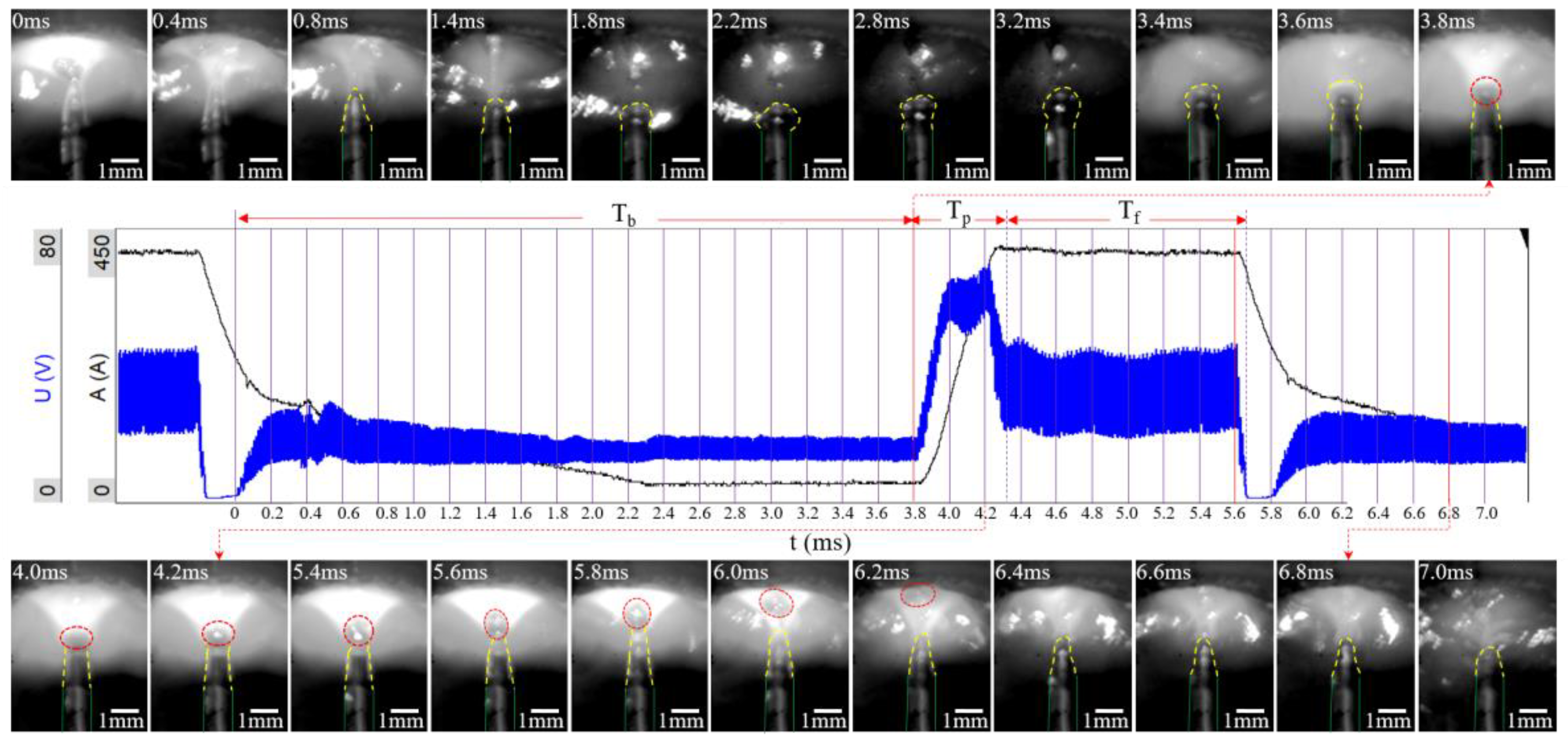
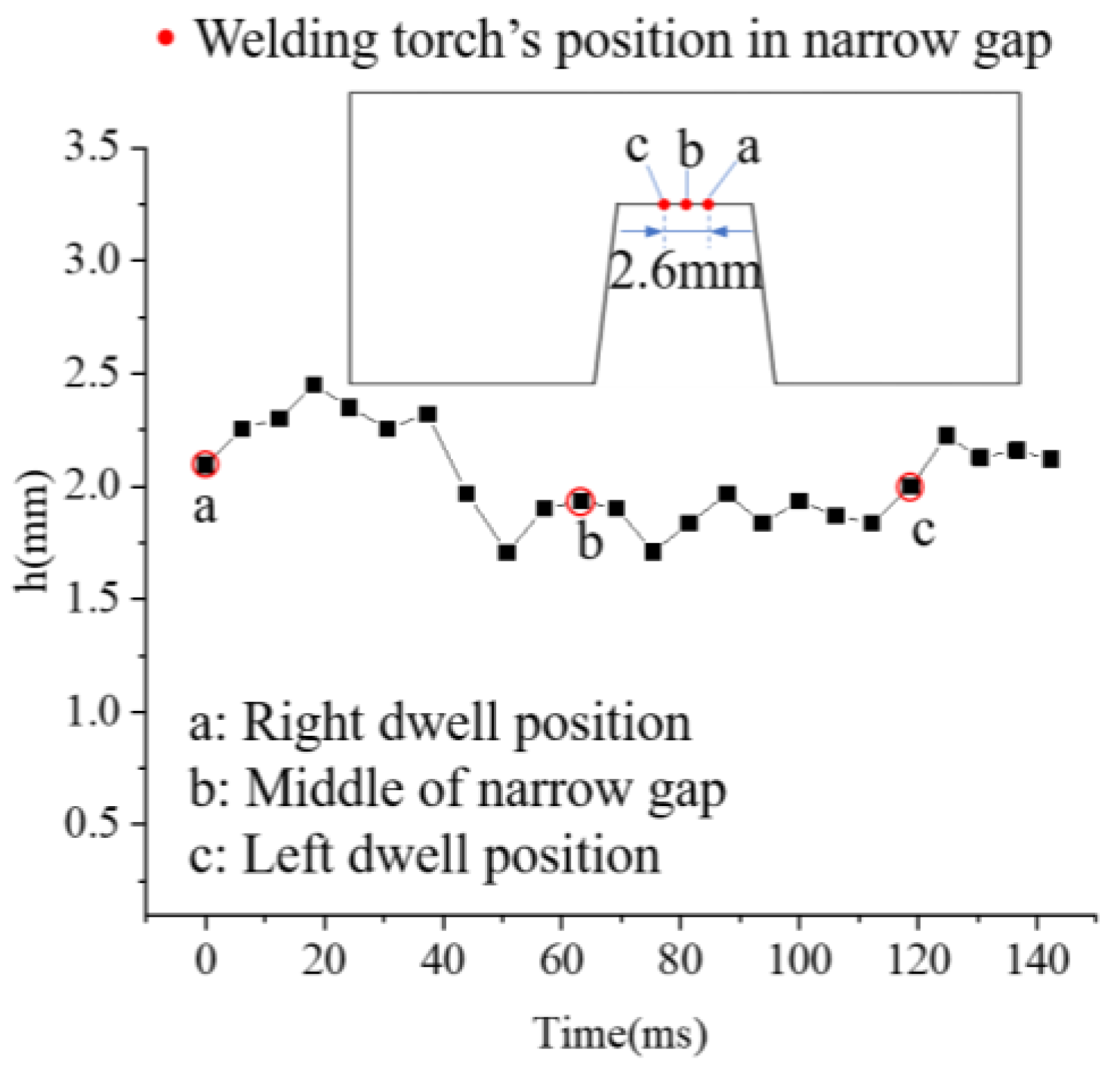
3.1.2. When the Welding Torch Oscillated with 2.6 mm

Increasing the oscillation width, the arc will be influenced by the sidewall and deviate slightly towards the sidewall as the welding torch near the sidewall of groove. As shown in Figure 4, with an oscillation width of 2.6 mm, the arc shape and droplet transfer process at the sidewall dwell position of the welding torch. At 0.4 ms, the wire end starts to liquefy and prepares for droplet growth. Under the influence of the sidewall, the melting speed of the wire near one side of the sidewall is much higher than the other side under the minimum voltage, causing the wire end to form a slope, as shown at 1.4 ms. As the droplet continues to grow, the amount of molten metal on the wire end slope increases continuously. At 3.6 ms, a discharge channel begins to form from the wire tip to the groove. As the voltage and current continue to increase, the molten metal at the welding wire tip begins to move towards the groove bottom under the action of electromagnetic force. At 4.0 ms, a complete discharge channel was established between the molten metal at the wire end and the sidewall of the groove, and P1 represents the connection point of the discharge channel on the sidewall of the groove. The discharge channel at the connection point of the groove gradually moves from the sidewall to the bottom when the molten metal continuously moves towards the groove bottom surface. At 5.6 ms, the molten metal detaches from the welding wire tip and forms droplets, which move towards the groove bottom under the action of electromagnetic force. However, the droplet does not completely detach from the welding wire tip, but is connected through a liquid bridge, as shown in 5.8 ms. As the droplet continues to move towards the groove bottom, electromagnetic forces and surface tension cause the liquid bridge to bend or curve. The connection point between the discharge channel and the groove also moves to point P2 on the groove bottom, as shown in 6.0 ms. At 6.4 ms, the molten droplets, under the influence of electromagnetic forces, enter the weld pool near the groove sidewall position, which is advantageous for increasing the penetration of groove sidewall. The end of the liquid bridge connected to the molten droplet enters the molten pool together with the droplet, while the other end is converted into a V-shape and connected to the welding wire tip, as presented in 6.6 ms. The remaining liquid bridge eventually flows back to the welding wire tip under the action of interfacial tension and gravity, as presented in 6.8 ms. During the droplet transfer period, the arc morphology is trumpet-shaped, and it changes its angle to the groove sidewall. The change in arc deflection angle also transfers the heat output from the groove bottom surface to the groove sidewall, which is advantageous for sidewall fusion.
The arc morphology during the oscillating of the welding torch is presented in Figure 5. At 0 ms, the welding torch is near the right sidewall and influenced by the bevel sidewall, and the arc turns towards the right groove sidewall. The arc thermal output is mainly distributed on the sidewall and bottom of the groove. The angle of arc deflection towards the right sidewall gradually decreases when the welding torch oscillates to the left groove sidewall, as shown at 37.4 ms. At 50.8 ms, the welding torch oscillates towards the groove center. Meantime, the arc is in a trumpet shape and the opening direction is perpendicular to the groove bottom surface. The arc thermal output at this moment acts entirely on the groove bottom surface. As the welding torch continues to move in the direction of the left groove sidewall, the arc also gradually deviates towards the left sidewall. The deviation angle of the arc towards the left sidewall reaches its maximum value when the welding torch reaches the left groove sidewall.
During the oscillating of the welding torch, h is the distance from the welding wire tip to the groove bottom, as presented in Figure 6. At 0 ms, the welding torch is near the right groove sidewall, as shown in point “a” in Figure 6, where h is 2.1 mm. During the movement of the welding wire to the left groove sidewall, h fluctuates within a small range. As the welding wire oscillates to the groove center at point “b’’, h stabilizes at 1.93 mm. While the welding wire arrives at the left groove sidewall at point “c”, influenced by the sidewall, h experiences small-scale fluctuations again. As can be seen from the above, during the oscillating of the welding torch, although there is a small fluctuation in h between the welding wire tip and the groove bottom, it remains around 2.0 mm, indicating that the process of narrow gap welding is relatively stable as the welding torch oscillates with 2.6 mm.

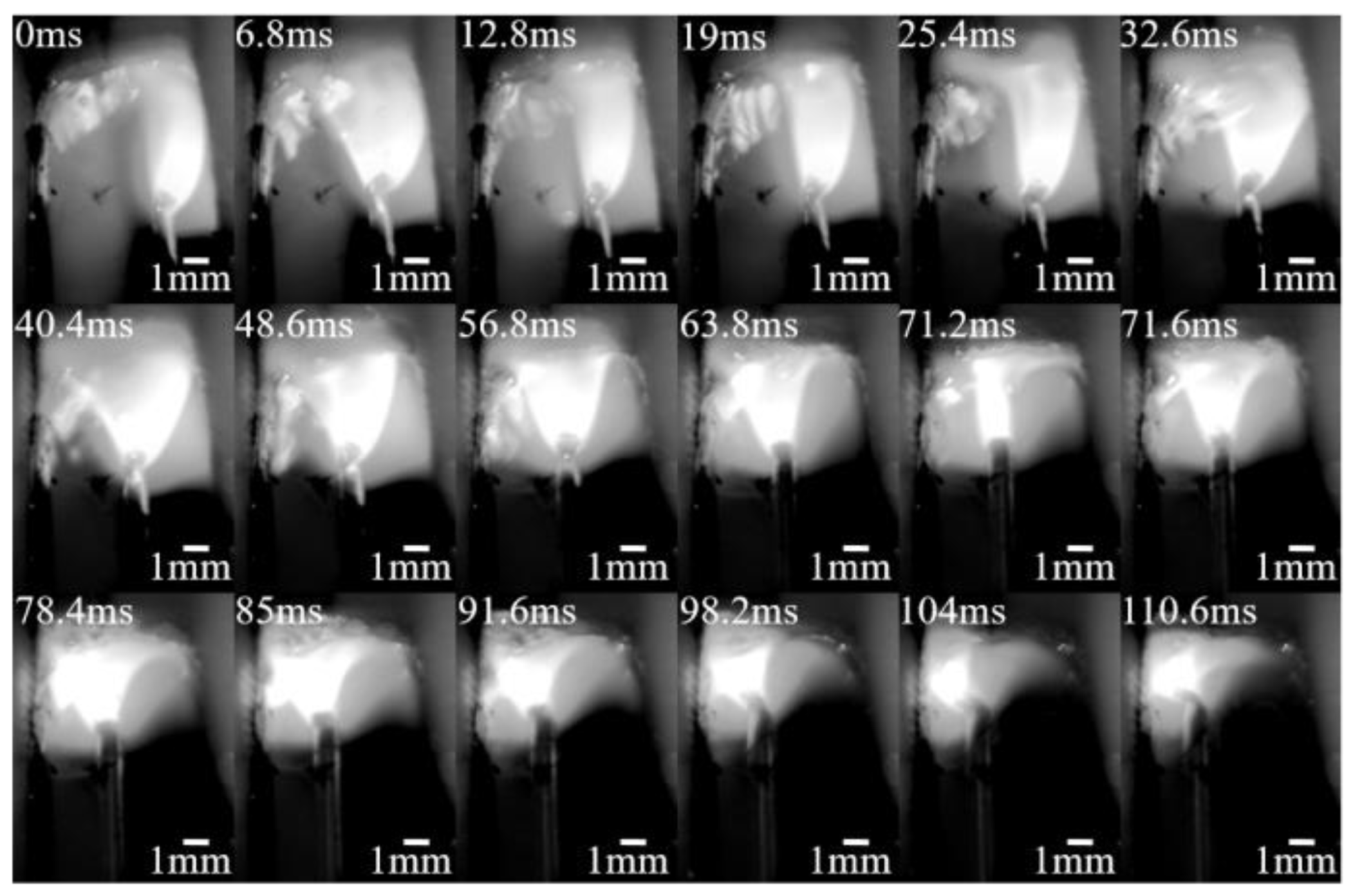
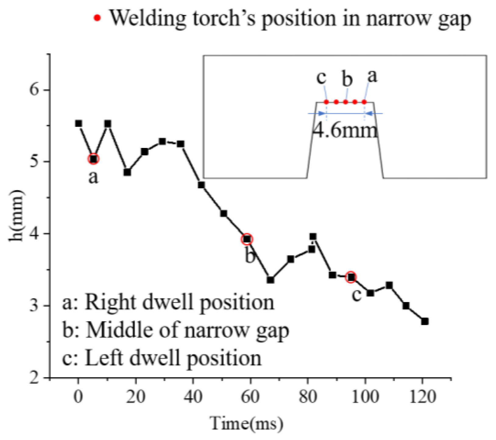
3.1.3. When the Welding Torch Oscillated with 4.6 mm

When the welding torch oscillated with 4.6 mm, the groove sidewall has a significant impact on the arc, as shown in Figure 7. At 9.2 ms, while the welding torch oscillates to the right groove sidewall, the wire tip is closer to the groove bottom surface, allowing the arc to reach the sidewall root. Due to the distance between the wire and the sidewall being smaller than the distance to the groove bottom and minimum voltage principle, the discharge channel gradually shifts to the space between the welding wire and the groove sidewall. The arc also climbs from the root of the sidewall to the middle, as shown at 29 ms. As the welding process continues, at 43.2 ms, the arc reaches the highest point of the sidewall and forms a relatively stable discharge channel. The analysis above indicates that within the initial 43.2 ms of the set 70 ms sidewall dwell time, the arc changes from the sidewall root to the sidewall middle. During this period, the arc is in a constant adjustment state, indicating an unstable welding process. After 43.2 ms, the distance from the welding wire tip to the groove bottom is relatively stable. However, there are still instances of instability, as shown at 68.4 ms. The discharge channel is established within the h scope, and quickly transfers to the groove sidewall position within 0.2 ms. This significantly increases the instability of the welding.
The droplet transfers and arc behavior during the later stage of sidewall dwell are shown in Figure 8. Due to the large distance h and the minimum voltage principle, the arc discharge channel is first built between the welding wire tip and the sidewall, as shown in 3.2 ms. As the droplets continue to grow, they gradually detach from the welding wire tip under the effect of electromagnetic force and completely detach from the welding wire tip at 4.2 ms. Similar to the previous situation, there is a liquid bridge connecting the welding wire tip and the droplet. As the droplet continues to move towards the groove bottom, gravity, electromagnetic force, and surface tension cause the liquid bridge to bend or curve, as shown at 5.0 ms. Finally, the liquid bridge breaks on the side close to the droplet at 6.0 ms. Electromagnetic force causes the droplets to enter the welding pool completely at 7.8 ms, with the droplet’s impact point located on the side away from the sidewall at the junction between the welding wire and the bottom of the welding pool. The remaining liquid bridge breaks into three smaller droplets and enters the welding pool. All of the above indicates that the molten droplet transfer mode is one pulse with multiple droplets. After the arc establishes a discharge channel between the welding wire tip and the middle of the sidewall, the arc coverage gradually extends to the middle of the sidewall, which makes it easy for the groove sidewall to bite under large oscillation widths. In addition, the droplet transfer stage has a significant deviation compared with the preset electrical signal. The droplet not only completes its growth within the preset growth stage Tb, but also undergoes the process of detaching from the wire end. There is a significant deviation between the droplet transfer stage and the preset electrical signal, indicating that the excessive oscillation width seriously interferes with the droplet transfer process. The disordered transfer of molten droplets disrupts the stability of the welding process, resulting in poor quality of the weld seam formation.
As the welding torch oscillated with 4.6 mm, the arc morphology during the oscillating of the welding torch from the right dwell groove sidewall to the left dwell groove sidewall is presented in Figure 9. At 0 ms, the welding wire is near the right dwell groove sidewall. Due to h, almost all discharge channels are built between the welding wire tip and the right groove sidewall. The arc discharge channel transfers from the groove sidewall to the groove bottom when the welding torch oscillates towards the left groove sidewall, as shown at 12.8 ms. The arc is stretched within h scope, and the heat flux density of the arc is greatly reduced, making the color of the arc at the groove bottom in the field of view very light. At 56.8 ms, the arc appears in a trumpet shape, and the opening is perpendicular to the groove bottom as the welding torch oscillates to the groove center. As the welding torch continues to oscillate towards the left sidewall, the arc gradually turns towards the left sidewall at a small angle and reaches its maximum value at the left sidewall dwell position within 104 ms. The arc gradually moves towards the left sidewall at an increasing angle and reaches its maximum value when it reaches the left dwell sidewall at 104 ms.
The statistical distance h during the oscillation of the welding torch with an oscillation width of 4.6 mm is presented in Figure 10. When h is 5.0 mm, the welding torch is at the right dwell sidewall point “a”. h shows small fluctuations but tends to decrease when the arc oscillates towards the left sidewall. When the welding torch oscillates to point “b” in the groove center, h decreases to 4.0 mm, which results in a higher heat flux density of the arc in the discharge channel and a more complete display of the arc morphology in the field of view. h drops to 2.9 mm, while the welding torch arrives at the left dwell sidewall at 104 ms. The above analysis indicates that during the oscillation of the welding torch, the distance h is constantly adjusted, which also indicates that the welding process with an oscillation width of 4.6 mm is extremely unstable.

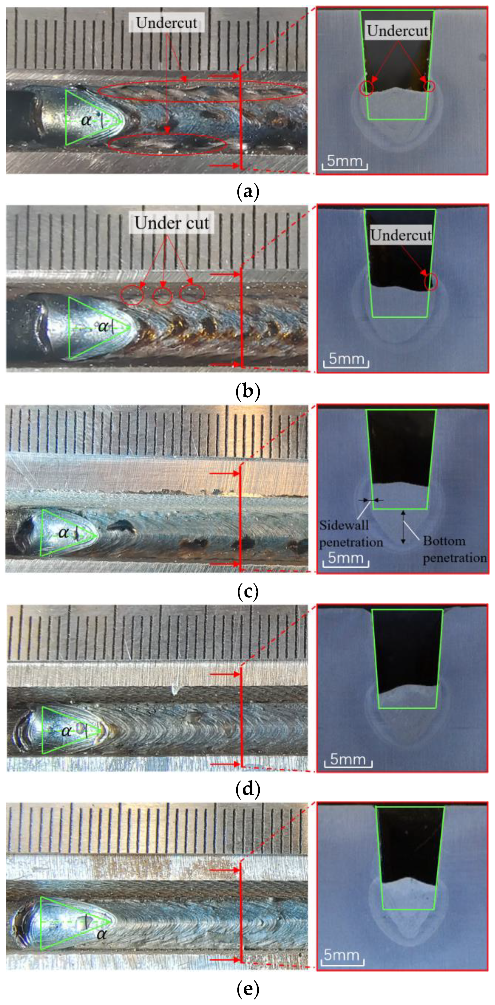
3.2. The Influence of Oscillation Width on Weld Formation

The oscillation parameters of the welding torch have a significant impact on the free surface morphology of the weld pool [52] and the surface formation of the weld bead, which becomes more obvious in the overhead welding station. The surface formation and cross section morphology of the weld seam with an oscillation width of 4.6 mm was presented in Figure 11a. The large oscillation width causes the arc to be too close to the groove sidewall. Although this is advantageous to increasing the groove sidewall penetration, it also makes it easy for undercut defects to appear on both groove sides, as shown by the red arrow in the figure. The large oscillation width widely distributes the arc thermal input among the groove bottom and groove sidewall, promoting the fast cooling of the welding pool and presenting a large trailing angle α. It should be noted that the weld seam is formed in a convex shape. This is because excessive oscillation width and arc pressure will squeeze the molten metal in the welding pool back to the groove bottom. Due to gravity, it solidifies faster, resulting in a convex surface formation of the weld seam. The undercut on both sides of the groove is significantly improved, changing from continuous undercut to intermittent undercut, when the oscillation width is 3.6 mm, as presented in Figure 11b. When the welding torch oscillates with 2.6 mm, the undercut defects on both welding seam sides disappear. At the same time, the penetration of the groove sidewall also decreases. The external convex formation of the weld bead has also been greatly improved, as shown in Figure 11c. When the oscillation width is reduced to 1.6 mm, the arc is mainly concentrated in the welding seam center, which allows the welding pool to obtain sufficient heat input and be stretched longer, resulting in a smaller trailing angle of the weld pool. As the oscillation width decreases, the molten pool gathers more momentum and moves to the weld seam center due to gravity, resulting in a convex morphology after solidification, as presented in Figure 11d. While the welding torch does not oscillate, the arc’s spreading impact on the welding pool is minimized while the welding seam with a convex appearance is more obvious. In contrast, all the arc thermal input is concentrated in the weld seam, allowing the welding pool flow to fully extend and present a smaller trailing angle. This greatly improves the heat input in the weld seam center, making the weld seam bottom deep and narrow, while the sidewall has almost no deep penetration, which can easily cause sidewall lack of fusion.

4. Discussion

As is well known, most of the welding heat input comes from the arc, and a portion comes from the droplet. As the welding torch is not oscillating, the arc points vertically towards the groove bottom surface, which is presented in Figure 12a. Due to the electromagnetic force, the molten droplets overcome gravity and fall into the welding pool. The heat transferred through the arc and molten droplets predominantly affect the center of the weld, resulting in a narrow and deep fusion zone at the bottom. However, the sidewalls receive a minimal amount of heat input, leading to insufficient fusion and the occurrence of incomplete sidewall fusion. Additionally, under the influence of gravity, the welding pool gathers in the groove center. Although the arc pressure can maintain the surface morphology of the welding pool, after the arc extinguishes, the welding pool flows back to the groove center under gravity and solidifies, forming a convex profile, as shown by the blue curve in Figure 12d. Figure 12b shows the arc morphology when the oscillation width is 2.6 mm and the welding torch is in the right dwell sidewall. Due to the minimum voltage principle, the arc deflects at a small angle towards the groove sidewall, resulting in a relatively greater heat input to the sidewall and forming a certain sidewall penetration. At the same time, the oscillation of the welding torch also spreads the welding pool to both weld seam sides and solidifies to form a relatively flat surface morphology, as shown in Figure 12e. When the oscillation width is 4.6 mm and the welding torch oscillates to the sidewall dwell position, the arc changes from the groove root to the middle of the groove sidewall, as presented in Figure 12c. The entire arc thermal input affects the groove sidewall, causing a deeper sidewall penetration. The molten droplets, under the influence of electromagnetic forces, overcome gravity and move towards the weld pool. During this period, the electromagnetic forces are reflected by the sidewall, ultimately pushing the droplets towards the side of the weld wire, away from the sidewall. Therefore, all the heat input from the molten droplet is applied to the weld seam bottom, which forms a relatively shallow penetration due to relatively less heat input. Furthermore, excessive oscillation width causes the arc pressure to squeeze the molten metal in the weld pool back to the center of the weld, and under the influence of gravity, the surface of the weld solidifies, forming a convex shape.

5. Conclusions

This paper presented the effect of increased oscillation width on arc characteristics and droplet transfer of the narrow gap P-GMAW welding process at the overhead welding station. This study delves into the weld seam formation mechanism of narrow-gap P-GMAW welding in the overhead welding position. It avoids the occurrence of welding defects such as weld bumps, undercut, and the incomplete sidewall, thereby further improving the welding quality of thick-walled pipelines and laying a theoretical foundation for the optimization of narrow gap P-GMAW welding process. Thus, the welding formation quality of pipelines has been further improved, paving the way for the welding process optimization of the narrow-gap P-GMAW. In light of this, the following conclusions can be drawn:
(1)
At narrow gap P-GMAW overhead welding position, an appropriate oscillation width can achieve a stable welding process. The arc maintains a trumpet shape and is symmetrically distributed around the groove center when the welding torch does not oscillate. Increasing the oscillation width causes the arc to deflect towards the groove sidewall at a small angle, and the deflection angle increases with the increased oscillation width. However, when the oscillation width is too large, there will be an arc jumping phenomenon, which affects the welding stability.
(2)
When the welding process is stable, the mode of droplet transfer is one pulse per droplet, and the droplet landing point is close to the groove sidewall, which can increase the sidewall penetration and facilitate the groove sidewall fusion. Due to the influence of gravity, the droplet growth time in the overhead welding station is shorter than the pre-set time. With a significant oscillation width, the droplet falls into a position far away from the sidewall due to the influence of the sidewall, and the droplet transfer mode changes to multiple droplets in one pulse, greatly affecting the stability of the welding pool. Moreover, there is a significant dissimilarity between the actual droplet transfer stage and the preset electrical signal, resulting in significant fluctuations during the welding.
(3)
Due to gravity, the welding pool accumulates in the groove center and solidifies to form an outwardly convex weld morphology. With an appropriate oscillation width, the welding pool can be spread to both sides of the groove through the welding torch oscillation and solidify to form a relatively flat weld bead forming surface. However, if the oscillation width is too large, the welding pool will be squeezed towards the groove bottom, and under the action of gravity, the weld seam will form an outwardly convex weld bead.
(4)
The groove sidewall penetration increases with the increase of the oscillation width during overhead welding, but an excessively large oscillation width can lead to the occurrence of undercut defects. On the other hand, the groove bottom penetration decreases with the increase of the oscillation width, but a smaller oscillation width carries the risk of sidewall lack of fusion. Therefore, selecting an appropriate oscillation width can not only achieve a stable narrow gap overhead welding process, but can also ensure a relatively flat weld bead-forming surface while ensuring welding penetration. Based on the groove dimensions and welding process parameters of X80 steel used in this study, an oscillation width of 2.6 mm is recommended.

Author Contributions

Conceptualization, Y.B. and J.Z.; Methodology, R.X.; Software, Y.B.; Validation, Y.B. and Y.X.; Formal analysis, Y.X.; Investigation, Y.B.; Resources, R.X.; Data curation, Y.B.; Writing—original draft preparation, Y.B.; Writing—review and editing, R.X.; Visualization, J.Z.; Supervision, Y.X.; Project administration, R.X.; Funding acquisition, J.Z. All authors have read and agreed to the published version of the manuscript.

Funding

This research was funded by the National Natural Science Foundation of Xinjiang, grant number 2022D01C391, The Science and Technology Innovations Project of the Outstanding Doctor of Xinjiang University, grant number XJUBSCX-201906, and Technology Innovation Team for Robots and Intelligent Equipment, grant number 2022D14002.

Data Availability Statement

Not applicable.

Conflicts of Interest

The authors declare no conflict of interest.

Abbreviations

TbTime of droplet generation
TpTime of droplet detachment
TfTime of droplet descent
hdistance between the welding wire tip and the groove bottom
tTime
P-GMAWPulse gas metal arc welding
GMAWGas metal arc welding
CFDComputational Fluid Dynamics
MAGMetal Active Gas Arc Welding
CTWDContact Tip to Work Distance

References

  1. Iwata, S.; Murayama, M.; Kojima, Y. Application of Narrow Gap Welding Process with High Speed Rotating Arc to Box Column Joints of Heavy Thick Plates. JFE Tech. Rep. 2009, 14, 16–21. [Google Scholar]
  2. Biswas, P.; Mandal, N.R.; Vasu, P.; Padasalag, S. Analysis of welding distortion due to narrow-gap welding of upper port plug. Fusion. Eng. Des. 2010, 85, 780–788. [Google Scholar] [CrossRef]
  3. Qin, G.L. Development and application of narrow gap gas shielded welding process. Metalwork. Hot Work 2022, 9, 8–20. [Google Scholar]
  4. Shen, J.J.; Gonçalves, R.; Choi, Y.T.; Lopes, J.G.; Yang, J.; Schell, N.; Kim, H.S.; Oliveira, J.P. Microstructure and mechanical properties of gas metal arc welded CoCrFeMnNi joints using a 410 stainless steel filler metal. Mat. Sci. Eng. A. 2022, 857, 144025. [Google Scholar] [CrossRef]
  5. Shen, J.J.; Gonçalves, R.; Choi, Y.T.; Lopes, J.G.; Yang, J.; Schell, N.; Kim, H.S.; Oliveira, J.P. Microstructure and mechanical properties of gas metal arc welded CoCrFeMnNi joints using a 308 stainless steel filler metal. Scripta. Mater. 2023, 222, 115053. [Google Scholar] [CrossRef]
  6. Shen, J.J.; Agrawal, P.; Rodrigues, T.A.; Lopes, J.G.; Schell, N.; Zeng, Z.; Mishra, R.S.; Oliveira, J.P. Gas tungsten arc welding of as-cast AlCoCrFeNi2.1 eutectic high entropy alloy. Mater. Design. 2022, 223, 111176. [Google Scholar] [CrossRef]
  7. Li, W.H.; Gao, K.; Wu, J.; Wang, J.Y.; Ji, Y.H. Groove sidewall penetration modeling for rotating arc narrow gap MAG welding. Int. J. Adv. Manuf. Technol. 2015, 78, 573–581. [Google Scholar] [CrossRef]
  8. Zhu, C.X.; Tang, X.H.; He, Y.; Lu, F.G.; Cui, H.C. Effect of preheating on the defects and microstructure in NG-GMA welding of 5083 Al-alloy. J. Mater. Process. Technol. 2018, 251, 214–224. [Google Scholar] [CrossRef]
  9. Xu, G.X.; Li, L.; Wang, J.Y.; Zhu, J.; Li, P.F. Study of weld formation in swing arc narrow gap vertical GMA welding by numerical modeling and experiment. Int. J. Adv. Manuf. Technol. 2018, 96, 1905–1917. [Google Scholar] [CrossRef]
  10. Wu, D.; Chen, Y.X.; Chen, H.B.; Chen, S.B. Influences of weaving parameters on dynamic characteristics and stability control of the droplet transfer in arc-weaving P-GMAW process. Int. J. Adv. Manuf. Technol. 2022, 119, 5233–5250. [Google Scholar] [CrossRef]
  11. Dai, Y.; Li, C.K.; Wang, J.X.; Gu, Y.F.; Shi, Y. Study on the weld pool oscillation behavior during pulsed gas metal arc welding. J. Manuf. Process. 2022, 84, 327–343. [Google Scholar] [CrossRef]
  12. Huang, J.; Chen, T.; Huang, D.Q.; Xu, T.Z. Study on the Effect of Pulse Waveform Parameters on Droplet Transition, Dynamic Behavior of Weld Pool, and Weld Microstructure in P-GMAW. Metals 2023, 13, 199. [Google Scholar] [CrossRef]
  13. Liu, W.J.; Jia, Z.B.; Yue, J.F.; Liu, H.H.; Li, L.Y. Arc interruption phenomena and internal causes in narrow gap P-GMAW. Weld. World 2020, 64, 1779–1787. [Google Scholar] [CrossRef]
  14. Liu, W.J.; Li, L.Y.; Yue, J.F.; Yan, P.J.; Liu, X.H. Research on the “jump sidewall” behavior and its signal characteristics in narrow gap P-MAG welding. Int. J. Adv. Manuf. Technol. 2017, 91, 1189–1196. [Google Scholar] [CrossRef]
  15. Liu, W.J.; Zhang, Y.F.; Meng, L.Z.; Yue, J. An innovative sensing method for seam tracking based on the arc ‘jump sidewall’ behavior. J. Mech. Sci. Technol. 2023, 37, 2325–2332. [Google Scholar] [CrossRef]
  16. Zhang, G.; Shi, Y.; Zhu, M.; Fan, D. Arc characteristics and metal transfer behavior in narrow gap gas metal arc welding process. J. Mater. Process. Technol. 2017, 245, 15–23. [Google Scholar] [CrossRef]
  17. Gu, Y.F.; He, G.Y.; Shi, G.; He, W.; Zhu, M. Detection and analysis of arc shape and droplet transfer behavior of narrow gap GMAW. J. Shanghai Jiao Tong Univ. 2016, 50, 1526–1529. [Google Scholar] [CrossRef]
  18. Xu, W.H.; Lin, S.B.; Fan, C.L.; Fan, C.L. Prediction and optimization of weld bead geometry in oscillating arc narrow gap all-position GMA welding. Int. J. Adv. Manuf. Technol. 2015, 79, 183–196. [Google Scholar] [CrossRef]
  19. Xu, W.H.; Lin, S.B.; Fan, C.L.; Yang, C.L. Weld bead formation in oscillating arc narrow gap vertical-up GMAW process. Trans. China Weld. Inst. 2015, 36, 56–60. [Google Scholar]
  20. Xu, W.H.; Lin, S.B.; Fan, C.L.; Yang, C.L. Evaluation on microstructure and mechanical properties of high-strength low-alloy steel joints with oscillating arc narrow gap GMA welding. Int. J. Adv. Manuf. Technol. 2014, 75, 1439–1446. [Google Scholar] [CrossRef]
  21. He, Y.; Tang, X.H.; Zhu, C.X.; Lu, F.G.; Cui, H.C. Study on insufficient fusion of NG-GMAW for 5083 Al alloy. Int. J. Adv. Manuf. Technol. 2017, 92, 4303–4313. [Google Scholar] [CrossRef]
  22. Zhu, C.X.; Cheon, J.; Tang, X.H.; Na, S.J.; Lu, F.G.; Cui, H.C. Effect of swing arc on molten pool behaviors in narrow-gap GMAW of 5083 Al-alloy. J. Mater. Process. Technol. 2018, 259, 243–258. [Google Scholar] [CrossRef]
  23. Zhan, X.H.; Liu, X.B.; Wei, Y.H.; Chen, J.C.; Chen, J.; Liu, H.B. Microstructure and property characteristics of thick Invar alloy plate joints using weave bead welding. J. Mater. Process. Technol. 2017, 244, 97–105. [Google Scholar] [CrossRef]
  24. Chen, Y.B.; Feng, J.C.; Li, L.Q.; Li, Y.; Chang, S. Effects of welding positions on droplet transfer in CO2 laser-MAG hybrid welding. Int. J. Adv. Manuf. Technol. 2013, 68, 1351–1359. [Google Scholar] [CrossRef]
  25. Xu, W.H. Research on Droplet Transfer and Weld Formation of Swing Arc Narrow GAP MAG Welding for Various Positions in Space. Doctoral Thesis, Harbin Institute of Technology, Harbin, China, 2015. [Google Scholar]
  26. Wang, D.Z.; Chen, G.; Zhang, Y.; Zhu, J.; Wang, J.Y. Effect of spatial welding positions on molten droplet transfer. J. Jiangsu Univ. Sci. Technol. 2018, 32, 633–636. [Google Scholar] [CrossRef]
  27. Cai, X.Y.; Lin, S.B.; Cheng, Y.X.; Yang, D.T.; Yang, C.L.; Fan, C.L. The effects of double groove type on the backing weld penetration in swing arc vertical-up MAG welding. Weld. World 2019, 63, 1133–1143. [Google Scholar] [CrossRef]
  28. Wang, Z.R.; Zhang, S.B.; Yang, Z.L.; Yang, Y.C. Influence of gap on droplet transition of GMAW vertical welding and characteristics of temperature field. Trans. China Weld. Inst. 2019, 40, 89–94, 165. [Google Scholar]
  29. Ebrahimi, A.; Babu, A.; Kleijn, C.R.; Hermans, M.J.M.; Richardson, I.M. The Effect of Groove Shape on Molten Metal Flow Behaviour in Gas Metal Arc Welding. Materials 2021, 14, 7444. [Google Scholar] [CrossRef]
  30. Wang, J.Y.; Ren, Y.S.; Yang, F.; Guo, H.B. Novel rotation arc system for narrow gap MAG welding. Sci. Technol. Weld. Join. 2007, 12, 505–507. [Google Scholar] [CrossRef]
  31. Zhao, B.; Fan, C.L.; Yang, C.L. Characteristics of the electrode melting phenomena in narrow gap MAG high-rotating-speed arc welding. In Proceedings of the Joint China-Russia Symposium on Advanced Materials Processing Technology, Harbin, China, 21–22 August 2006. [Google Scholar]
  32. Yang, C.L.; Guo, N.; Lin, S.B.; Fan, C.L.; Zhang, Y.Q. Application of rotating arc system to horizontal narrow gap welding. Sci. Technol. Weld. Joi. 2009, 14, 172–177. [Google Scholar] [CrossRef]
  33. Duan, B.; Wang, J.C.; Lu, Z.H.; Zhang, J.X.; Zhang, C.H. Parameter analysis and optimization of the rotating Arc NG-GMAW welding process. Int. J. Simul. Model. 2018, 17, 170–179. [Google Scholar] [CrossRef]
  34. Guo, N.; Lin, S.B.; Zhang, L.; Yang, C.L. Metal transfer characteristics of rotating arc narrow gap horizontal GMAW. Sci. Technol. Weld. Join. 2009, 14, 760–764. [Google Scholar] [CrossRef]
  35. Guo, N.; Zhang, J.; Han, Y.F.; Zhang, L.L.; Yuan, X. Effects of Welding Parameters on Metal Transfer Process in Rotating Arc Narrow Gap Horizontal GMAW. Trans. Jwri. 2012, 2011, 5–7. [Google Scholar] [CrossRef]
  36. Guo, N.; Han, Y.F.; Jia, C.B.; Du, Y.P. Effects of wire rotating frequency on metal transfer process in rotating arc narrow gap horizontal GMAW. Adv. Mater. Res. 2011, 189–193, 3395–3399. [Google Scholar] [CrossRef]
  37. Guo, N.; Wang, M.R.; Guo, W.; Yu, J.B.; Feng, J.C. Effect of rotating arc process on molten pool control in horizontal welding. Sci. Technol. Weld. Join. 2014, 19, 385–391. [Google Scholar] [CrossRef]
  38. Li, W.H.; He, C.F.; Chang, J.S.; Wang, J.Y.; Wu, J. Modeling of weld formation in variable groove narrow gap welding by rotating GMAW. J. Manuf. Process. 2020, 57, 163–173. [Google Scholar] [CrossRef]
  39. Li, W.H.; Gao, K.; Wu, J.; Hu, T.; Wang, J.Y. SVM-based information fusion for weld deviation extraction and weld groove state identification in rotating arc narrow gap mag welding. Int. J. Adv. Manuf. Technol. 2014, 74, 1355–1364. [Google Scholar] [CrossRef]
  40. Li, W.H.; Sun, D.D.; Yang, F.; Wang, J.Y.; Ren, Y.S. A new type of welding deviation extraction algorithm based on rotating arc sensor for narrow gap mag welding. Mater. Sci. Tech.-Lond. 2011, 19, 48–52. [Google Scholar]
  41. Meng, Y.F.; Li, G.; Gao, M.; Zeng, X.Y. Effects of groove parameters on space constraint of narrow gap laser-arc hybrid welding. J. Manuf. Process. 2018, 33, 144–149. [Google Scholar] [CrossRef]
  42. Liu, G.Q.; Tang, X.H.; Han, S.Y.; Lu, F.G.; Cui, H.C. Influence of inter wire angle on undercutting formation and arc behavior in pulsed tandem narrow-gap GMAW. Mater. Design 2020, 193, 108795. [Google Scholar] [CrossRef]
  43. Liu, Q.; Wu, D.; Wang, Q.; Zhang, P.; Yan, H.; Sun, T.; Zeng, J.; Yan, M.; Liu, Z.; Li, R. Research Status of Stability in Dynamic Process of Laser-Arc Hybrid Welding Based on Droplet Transfer Behavior: A Review. Coatings 2023, 13, 205. [Google Scholar] [CrossRef]
  44. Cai, X.Y.; Fan, C.L.; Lin, S.B.; Yang, C.L.; Hu, L. Effects of shielding gas composition on arc characteristics and droplet transfer in tandem narrow gap GMA welding. Sci. Technol. Weld. Join. 2016, 22, 446–453. [Google Scholar] [CrossRef]
  45. Mirakhorli, F.; Cao, X.; Pham, X.T.; Wanjara, P.; Fihey, J.L. Technical challenges in narrow gap root pass welding during tandem and hybrid laser-arc welding of a thick martensitic stainless steel. Mater. Sci. Forum. 2016, 879, 1305–1310. [Google Scholar] [CrossRef]
  46. Liu, L.L.; Wang, Z.L.; Zhang, T.Y.; Ba, X.L. Analysis of metal transfer and weld forming characteristics in triple-wire gas indirect arc welding. Int. J. Adv. Manuf. Technol. 2022, 120, 6777–6788. [Google Scholar] [CrossRef]
  47. Cai, B.; Fu, J.; Zhao, Y.; Chen, F.; Qin, Y.; Song, S. Effect of Alternating Magnetic Field on Arc Plasma Characteristics and Droplet Transfer during Narrow Gap Laser-MIG Hybrid Welding. Metals 2021, 11, 1712. [Google Scholar] [CrossRef]
  48. Wang, J.F.; Sun, Q.J.; Zhang, T.; Zhang, S.; Liu, Y.B.; Feng, J.C. Arc characteristics in alternating magnetic field assisted narrow gap pulsed GTAW. J. Mater. Process. Technol. 2018, 254, 254–264. [Google Scholar] [CrossRef]
  49. Ebrahimi, A.; Kleijn, C.R.; Hermans, M.J.M.; Richardson, I.M. The effects of process parameters on melt-pool oscillatory behaviour in gas tungsten arc welding. J. Phys. D Apply. Phys. 2021, 54, 275303. [Google Scholar] [CrossRef]
  50. Liu, H.S.; Xue, R.L.; Zhou, J.P.; Bao, Y.; Xu, Y. Applying Statistical Models to Optimize the Weld Bead Geometry in the Vertical Oscillation Arc Narrow Gap All-Position GMAW. Appl. Sci. 2023, 13, 6801. [Google Scholar] [CrossRef]
  51. Liu, H.S.; Xue, R.L.; Zhou, J.P.; Bao, Y.; Xu, Y. Effects of Oscillation Width on Arc Characteristics and Droplet Transfer in Vertical Oscillation Arc Narrow-Gap P-GMAW of X80 Steel. Metals 2023, 13, 1057. [Google Scholar] [CrossRef]
  52. Ebrahimi, A.; Kleijn, C.R.; Richardson, I.M. A simulation-based approach to characterize melt-pool oscillations during gas tungsten arc welding. Int. J. Heat. Mass. Tran. 2021, 164, 120535. [Google Scholar] [CrossRef]
Figure 1. Schematic diagram of the (a) overhead oscillation arc narrow gap P-GMAW system, and (b) welding arc trajectory in the narrow gap P-GMAW.
Metals 13 01314 g001
Figure 2. Construction diagram of data collection platform.
Metals 13 01314 g002
Figure 3. The arc morphology and droplet transfer behavior corresponding to the electrical signals when the welding torch does not oscillate. (The yellow line indicates the shape change at the wire tip, and the red line indicates the droplet).
Metals 13 01314 g003
Figure 4. The arc morphology and droplet transfer behavior on the right sidewall corresponding to the electrical signals when the welding torch oscillated with 2.6 mm. (The yellow line indicates the shape change at the wire tip, and the red line indicates the drop-let).
Metals 13 01314 g004
Figure 5. The arc morphology on the left sidewall when the welding torch oscillated with 2.6 mm.
Metals 13 01314 g005
Figure 6. The corresponding h at different times when the welding torch moves from the left wall of the groove to the right wall with an oscillation width of 2.6 mm.
Metals 13 01314 g006
Figure 7. The arc morphology on the right sidewall when the welding torch oscillated with 4.6 mm.
Metals 13 01314 g007
Figure 8. The arc morphology and droplet transfer behavior corresponding to the electrical signals when the welding torch oscillated with 4.6 mm. (The yellow line indicates the shape change at the wire tip, and the red line indicates the droplet).
Metals 13 01314 g008
Figure 9. The arc morphology when the welding torch oscillated with 4.6 mm.
Metals 13 01314 g009
Figure 10. The corresponding h at different times when the welding torch moves from the left wall of the groove to the right wall with an oscillation width of 4.6 mm.
Metals 13 01314 g010
Figure 11. Weld seam morphology with different oscillation widths (a) 4.6 mm, (b) 3.6 mm, (c) 2.6 mm, (d) 1.6 mm, and (e) 0 mm.
Metals 13 01314 g011
Figure 12. Arc behavior under different oscillation widths: (a) 0 mm, (b) 2.6 mm, (c) 4.6 mm, and a diagram of arc and droplet with different oscillation widths: (d) 0 mm, (e) 2.6 mm, (f) 4.6 mm.
Metals 13 01314 g012
Table 1. Chemical composition of base metal and welding wire (wt%).
MaterialCMnSiSPNiCuCrFe
Substrate0.0631.830.280.00060.0110.030.040.03Bal.
Wire0.081.370.590.0120.0120.0110.100.021Bal.
Disclaimer/Publisher’s Note: The statements, opinions and data contained in all publications are solely those of the individual author(s) and contributor(s) and not of MDPI and/or the editor(s). MDPI and/or the editor(s) disclaim responsibility for any injury to people or property resulting from any ideas, methods, instructions or products referred to in the content.

