Article

Influence of a Protective Coating on the Crystallization of an Amorphous Fe78Si13B9 Alloy

Osipyan Institute of Solid State Physics RAS, 142432 Chernogolovka, Russia
*
Author to whom correspondence should be addressed.
Metals 2023, 13(6), 1090; https://doi.org/10.3390/met13061090
Submission received: 13 May 2023 / Revised: 5 June 2023 / Accepted: 7 June 2023 / Published: 8 June 2023

Abstract

:
The effect of free volume on the crystallization of amorphous Fe78Si13B9 ribbons was studied using ultrasonic and thermal treatments. To maintain free volume under heating, amorphous samples were coated with a special protective Ta coating. It has been shown via X-ray diffraction that the fraction of the crystalline phase in the annealed coated amorphous ribbons is higher than in the corresponding uncoated samples. The use of ultrasonic treatment and the application of a protective coating lead to the formation of a larger proportion of the crystalline phase during annealing. Differences in crystallization kinetics are discussed under the assumption that the concentration of free volume in amorphous samples affects their crystallization, as well as the role of the Ta coating preventing the release of free volume to the surface during heat treatment.

Graphical Abstract

1. Introduction

Nanocrystalline materials formed on the basis of amorphous alloys attract great attention due to their unique physical properties [1,2,3,4,5]: strength (Al-based alloys [6]), magnetism (Fe-, Co-based [5,7,8,9,10,11,12,13]), corrosion resistance [14,15,16], etc. The properties of amorphous alloys can be significantly improved through forming an amorphous nanocrystalline structure. There are a lot of investigations devoted to the study of the structure and properties of amorphous and nanocrystalline materials, as well as to the features of crystallization of amorphous alloys of various compositions [17,18,19]. In this regard, nanocrystalline alloys based on the Fe–Si–B system are of great interest as a material with high magnetic properties. To form a nanostructure in amorphous alloys, heat treatment methods are often used [20,21,22]. However, heat treatment does not make it possible to create a nanostructure in all amorphous alloys. Alloys of the Fe–Si–B system can serve as an example. During the crystallization of amorphous alloys of this system, a structure with a relatively large grain size is formed. To create a nanocrystalline structure, Cu and Nb are added to Fe–Si–B alloys, which promote the formation of nanocrystals. Although Fe–Si–B–Cu–Nb (Finemet) alloys are widely used due to their unique soft magnetic properties, it should be noted that the introduction of Cu and Nb leads to a deterioration of magnetic properties, in particular magnetization. Another way to obtain a nanocrystalline structure is the use of plastic deformation (high pressure torsion, multiple rolling, etc.) [6,21,23,24,25,26,27]. This method was used to obtain a nanostructure in a number of alloys in which it could not be prepared via heat treatment. These alloys include alloys of the Fe–Si–B system. The formation of an amorphous nanocrystalline structure in the alloy of the Fe–Si–B system made it possible to significantly increase the saturation magnetization (by 40%) and surpass the level of saturation magnetization for Finemet-type alloys [28]. Amorphous Fe–Si–B alloys belong to one of the most widely studied groups of amorphous alloys [11,28,29,30]. The processes of crystallization during conventional heating [25,28], rapid heating [31], high-pressure torsion deformation, multiple rolling methods [28,32], crystallization under widthwise/lengthwise press, and annealing [30] were studied for alloys of different chemical compositions.
Plastic deformation (at temperatures well below Tg) leads to the formation of shear bands in the amorphous structure. The shear bands are regions of plastic deformation localization; they are characterized by a looser structure (regions of reduced density) [26,33,34,35,36,37,38,39]. According to different data, the width of shear bands can range from 5–30 nm [23,35] to hundreds of nm (10–210 nm [38]). At that, the density of the amorphous phase in a shear band can decrease by 1–12% [38]. In these areas, an increased concentration of free volume is observed [39], mass transfer processes can proceed faster, and crystallization is facilitated [6,20,40]. It should be noted that free volume in amorphous alloys can play a crucial role in crystallization processes. A change in the free volume can result in the formation of a structure with different structural parameters. For example, a nanostructure formed upon deformation consists of smaller nanocrystals than a nanostructure formed upon heat treatment [41,42]. In different amorphous alloys, deformation can promote both acceleration [43] and suppression of crystallization [30]. Changes in the structure upon deformation also depend on the orientation of the sample. For example, it was shown in [30] that the widthwise pressed treatment reduced free volume and suppressed crystallization to a larger degree than the lengthwise pressed treatment. The evolution of the structure under deformation depends on the value of the free volume.
For the deformation of amorphous alloys, the methods of high-pressure torsion and cold rolling are most often used. However, only disc-shaped specimens can be obtained via pressure torsion, and often the structure and, hence, the properties depend on the position in the specimen. During deformation via the high-pressure torsion method, the degree of deformation changes along the radius; in the case of rolling, the degree of deformation changes along the depth of the sample (the most deformed are the near-surface regions). Most recently, a new method of affecting the structure of amorphous alloys has arisen, namely, the method of ultrasonic treatment [44,45]. This method of influencing the structure has found application for both amorphous and crystalline materials [45,46]. Ultrasonic treatment is one of the deformation methods that allows varying free volume concentration in an amorphous material [44,46] and promoting structure rejuvenation similarly to thermal cycling [47,48]. Today, there are not many works on the investigation of a structure formed in amorphous alloys using this method. From currently known works [49,50], ultrasonic treatment was applied to only bulk amorphous alloys, and there are almost no data on the application of this method to amorphous ribbons.
As noted above, deformation leads to an increase in the fraction of free volume in the amorphous phase. It should be noted that free volume is one of the most important concepts that are widely used to describe and quantify many properties of amorphous materials, such as viscosity, glass transition, relaxation, diffusion, etc. [51,52,53,54]. The concept of free volume was formulated almost immediately after the production of the first amorphous alloys [55,56] and later developed in a number of works. Studies have shown that the concept of free volume diffusion appears to be universal for different types of materials. For example, the authors of [57] described two mechanisms of relaxation of glasses deposited from vapors, including, among other things, the release of free volumes to the surface. In a review [58] devoted to the study of nanostructured polymer glasses, thin films, nanocomposites, and nanospheres, the nonequilibrium dynamics (the exit of the system from equilibrium upon cooling) of the process and the determining role of free volume diffusion in the processes of aging and other structural transformations are analyzed.
However, during structural relaxation, heat treatment, or simply aging, the amount of free volume decreases [59]. Since amorphous alloys are usually obtained via rapid quenching of the melt, the structure of the quenched state is not equilibrium. A quenched amorphous alloy inherits the structure of the melt, including a lower density compared to a crystalline material of the same composition. During structure relaxation, when the material goes into a more equilibrium state, a change in the volume occurs. The increase in the density during structural relaxation is 0.3–0.5% [60], and this process is irreversible. This change occurs due to the release of free volume, and the structure becomes denser. During structural relaxation, the diffusion coefficient, viscosity, stress relaxation rate, internal friction, and superconducting transition temperature decrease, while an increase in the elastic moduli, thermal resistance, and embrittlement is observed [61]. Below the glass transition temperature, some properties can change both reversibly (electrical resistance, induced magnetic anisotropy) and irreversibly (internal friction, viscosity, diffusion mobility). The Curie temperature and coercive force can change both reversibly and irreversibly depending on the composition. Thus, the deformation of the samples contributes to an increase in the free volume; this is clearly seen in the temperature dependencies obtained via dilatometry [54,62].
During heat treatment, the free volume migrates to the sample surface and exits through the sample surface. This leads to a change in many physical properties [63,64] and, in particular, to embrittlement [65,66], which limits the use of such materials in industry. In order to maintain good physical properties, it is necessary to preserve free volume (prevent free volume from escaping through surfaces). This decrease can be prevented through using special protective coatings, as demonstrated in [67]. It was shown that the migration of free volume from the amorphous alloy to the coating material is thermodynamically unfavorable if the energy of vacancy formation in the coating material is higher than the energy of formation of an elementary free volume carrier (quasi-vacancies) in the amorphous phase. The maintenance of free volume using protective coatings will allow investigation of its effect on the processes of amorphous alloy crystallization. This work is devoted to the study of the effect of free volume on the crystallization of an amorphous Fe78Si13B9 alloy and the study of the features of crystallization of the amorphous phase under conditions of limited migration of free volume.

2. Materials and Methods

Alloy ingots with nominal compositions of Fe77Si13B10 were prepared through arc melting of a mixture of Fe (99.9%), Si (99.9%), and B (99.9%); they were melted three times to homogenization before melt quenching in a high-purity argon atmosphere. Amorphous Fe78Si13B9 was obtained through quenching the melt in the form of ribbons. When preparing the samples, capillaries with a slotted hole were used. The width of the ribbons was 1 cm, and the thickness was about 35 μm. The samples were subjected to isothermal annealing of various durations. The annealing temperature was 573–873 K. The amorphous samples were also subjected to ultrasonic treatment in an ultrasonic bath (the power was 100 W) for 1 h. After the ultrasonic treatment, a protective Ta coating was deposited onto both surfaces of the samples via cathode sputtering. The thickness of the coating was about 100–300 nm. The protective layer thickness was determined using a Supra Zeiss 50vp scanning electron microscope. The samples after the ultrasonic treatment and coating deposition and the reference samples were annealed simultaneously at different temperatures for 1 h. The structure was examined at each stage of processing (after amorphous alloy preparation, heat treatments, ultrasonic treatment, protective coating deposition, additional annealing, etc.). The structure of the Ta-coated samples and/or samples with ultrasonic treatment was compared to that of a control sample that had not been coated and had not been subjected to any pretreatment.
The structure of the samples was investigated through scanning (SEM) and transition electron microscopy (TEM) methods and via X-ray diffraction (XRD) using Co Kα radiation. Samples for TEM studies were prepared using ion milling. A VERSA 3D HighVac set-up with a focused ion beam (FIB) was used to prepare electron microscope foils from the near-surface regions of Ta-coated samples. The thermal analysis of the alloy was performed via differential scanning calorimetry (DSC) (Perkin-Elmer DSC-7).
In cases where, after treatment, the samples consisted of two phases (namely an amorphous phase and crystals), the diffraction peaks were decomposed into components (diffuse maximum corresponding to the scattering from the amorphous phase and a diffraction peak from the crystals). In the decomposition, data on the position and half-width of the diffuse maximum of the initial amorphous phase were used. In order to calculate the volume fraction of the crystalline phase in the partially crystalline alloys from X-ray diffraction data, a standard approach has been used that assumes that the volume fraction, Vc, of the crystalline phase may be determined as
Vc = Ic/(Ic +αIam),
where Ic and Iam are the integral intensity of the reflections of the crystalline phase and the amorphous phase, respectively, and α is a constant. In the formula, the coefficient α is constant, and it may be different for different systems. The constant α was assumed to be 1.05 for alloys of the Finemet type [68]. As it was shown in [69], the most correct values might be obtained through analyzing the angle range of the first diffuse halo, i.e., in the region of the best signal/noise ratio.

3. Results and Discussion

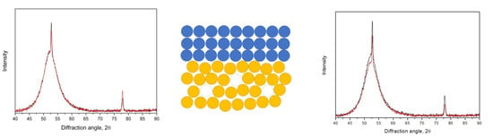
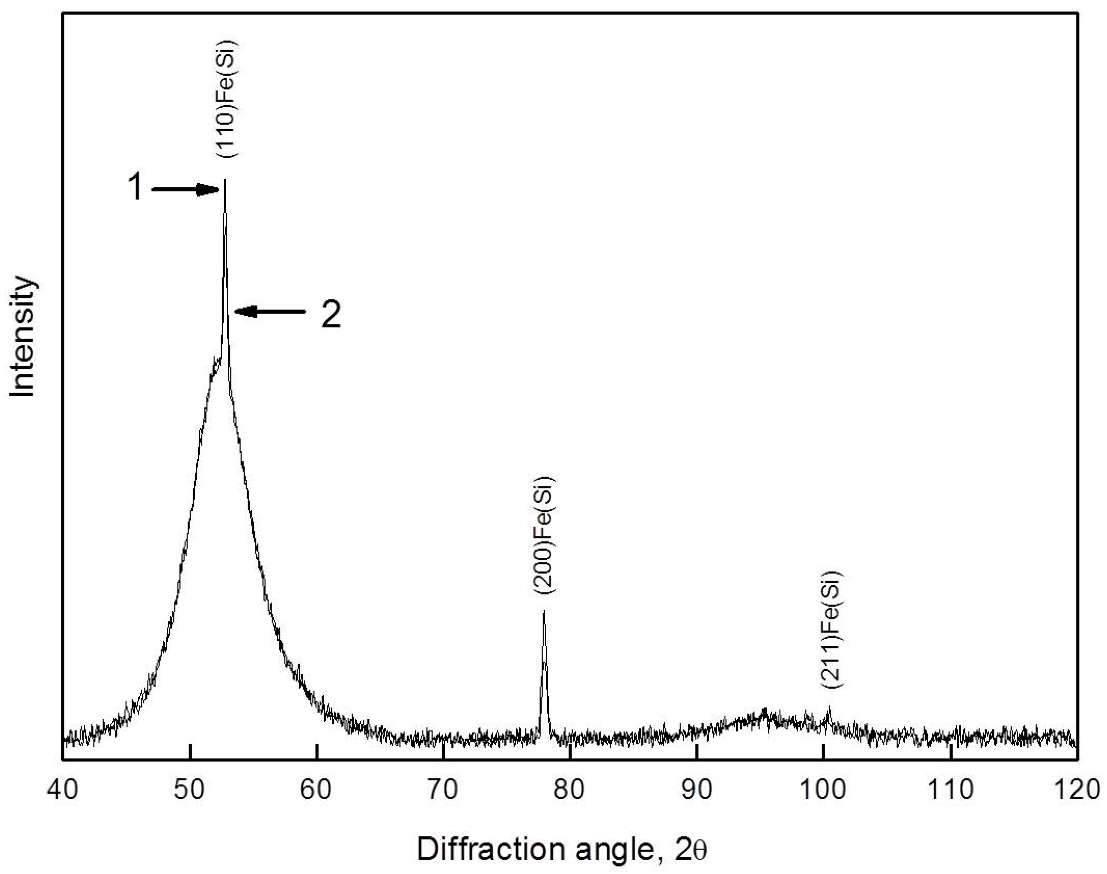
3.1. Crystallization of the as-Quenched Samples

The initial ribbons were amorphous. No signs of the crystalline phases are observed in the X-ray and electron diffraction patterns. Figure 1 shows the XRD pattern of the as-prepared sample.
To determine the heat treatment conditions, the samples were studied using the differential scanning calorimetry method. Figure 2 shows the DSC curve of the alloy. In the amorphous Fe78Si13B9 alloy, the transition from an amorphous to a crystalline state is carried out in two stages. The temperature of the first and second stages of crystallization (peaks) is 782 and 826 K, respectively (at a heating rate of 20 K/min).
The structure of the samples was studied after both isothermal annealing in a resistance furnace and heating at a constant rate in a calorimeter. Crystals of Fe(Si) solid solution are formed at the first stage of crystallization, and a eutectic reaction with the (Fe(Si) + Fe3B) formation occurs at the second crystallization stage. After the first stage of crystallization, the structure consists of crystals of a Fe(Si) solid solution and a remaining amorphous phase. The lattice parameter of the solid solution is 2.844 Å, which agrees with data in the known literature [69]. Figure 3 shows the X-ray diffraction pattern of the alloy after the first stage of crystallization.
Figure 4a,b show a transmission electron microscopic image (4a) and an electron diffraction pattern (4b), respectively, for the structure formed at the first stage of crystallization. The crystals have a pronounced dendritic shape. The size of the dendrites is 50–200 nm. They consist of several parts with a size of 20–70 nm. There are also individual crystals 20–50 nm in size. The orientation of the crystals is random. The electron diffraction pattern (Figure 4b) shows numerous reflections from crystals of the Fe(Si) phase. The electron diffraction pattern also contains a diffuse halo from the amorphous matrix.
It should be noted that the information obtained with the help of electron microscopy methods is local. Therefore, in further comparative studies, the main attention was paid to the analysis of the results obtained via X-ray diffraction. The depth of penetration of the used X-ray radiation into the sample in the region of the main diffuse maximum and the most intense diffraction line was about 12 μm and varied up to 28 μm in the studied angular range. Under these conditions, the structure was analyzed in the bulk of the sample. As noted above, when analyzing the X-ray diffraction patterns of samples containing amorphous and crystalline phases, the maxima were decomposed into components: a diffuse maximum from the amorphous phase and a diffraction reflection from the crystals. In this case, the parameters of the diffuse maximum of the initial amorphous alloy were taken into account. Based on the determined values of the integral intensities of the submaxima, a change in the proportion of the amorphous (or crystalline) component of the structure was calculated. The crystal size was calculated from the broadening of the diffraction peak and compared with the data obtained from the electron-microscopic studies.
To assess the role of free volume in the process of crystallization of the amorphous phase, the samples were subjected to ultrasonic treatment for 1 h. After this treatment, the samples remained amorphous. Then, a protective coating (Ta layer) was applied to both surfaces of the ribbon. Figure 5 shows the microstructure of a sample with a protective coating. The layer thickness is indicated in the figure. After applying the protective coating, the as-prepared sample and the coated and uncoated samples processed in the ultrasonic bath were subjected to isothermal annealing simultaneously.
Figure 6 shows XRD patterns of the samples after isothermal annealing at 703 K for 1 h (the initial stage of crystallization). The X-ray diffraction pattern contains maxima characteristic of both the amorphous phase (diffuse maxima in the region of 50–56° and 90–100°) and diffraction peaks corresponding to the crystalline phase (hkl indices are indicated in the figure). Annealing at 703 K for 1 h leads to the onset of the crystallization of the amorphous Fe78Si13B9 alloy.

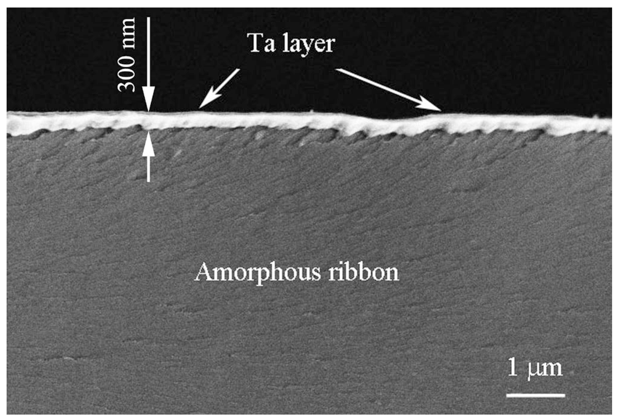
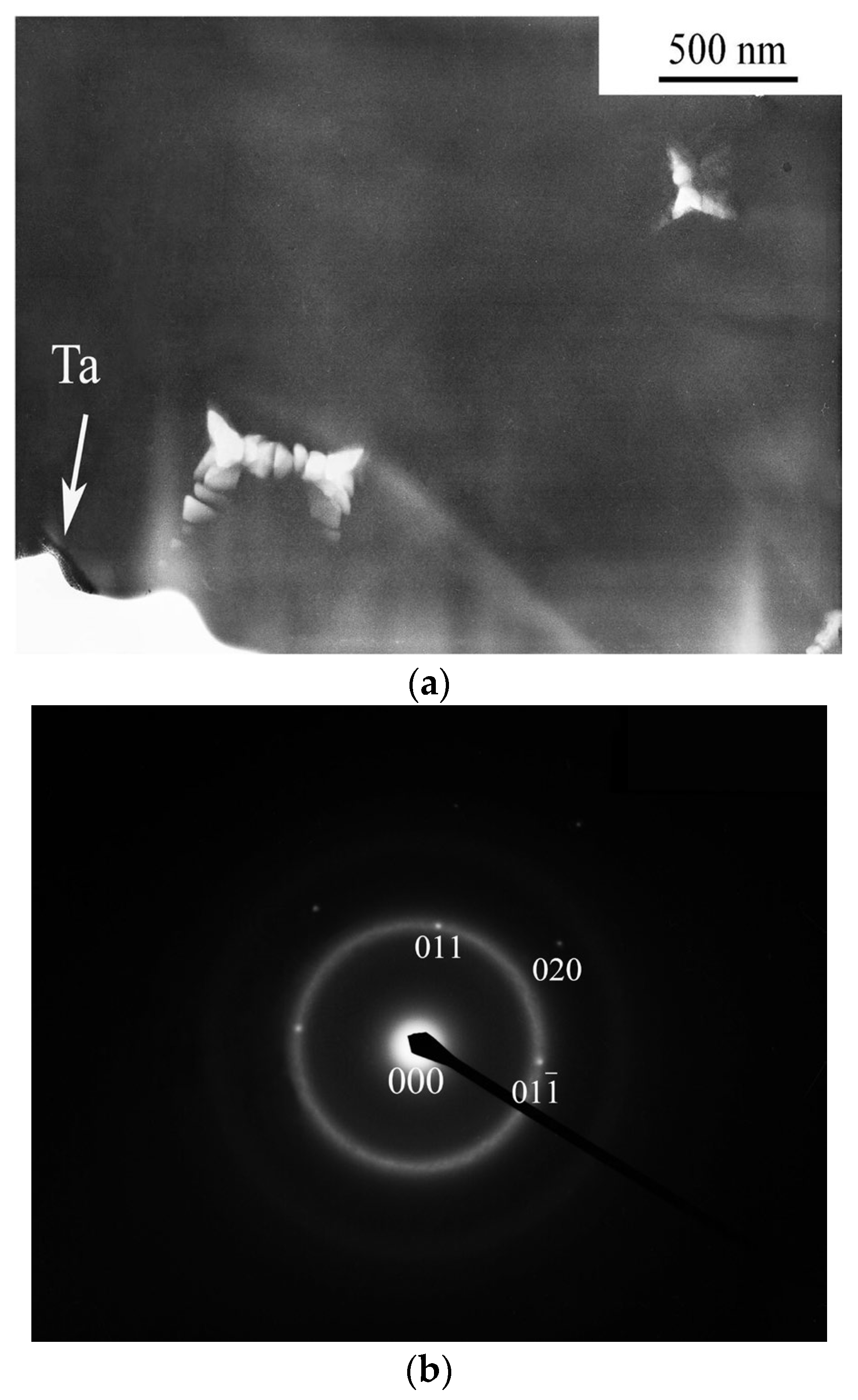
3.2. Crystallization of the Samples with a Ta Coating

Figure 7a shows a TEM image of the microstructure of an annealed sample (703 K, 1 h) with a protective coating. A corresponding electron diffraction pattern is shown in Figure 7b. The electron diffraction pattern shows a diffuse halo from the amorphous matrix and reflections from the crystalline phase. These reflections correspond to crystals of the Fe(Si) phase, which has a body-centered cubic lattice. The sample was prepared on a setup using focused ion beams. The near-surface regions of the sample with the remnants of the Ta layer are located in the lower part of the sample. The main part of the Ta layer was removed through polishing during electron microscopy foil preparation. It can be seen that the formation of crystals begins evenly over the sample. No effect of the protective coating on the predominant formation of crystals was found.
To estimate the fraction of the crystalline phase and the size of the formed crystals, the overlapping maxima of the XRD pattern were separated. Figure 8 shows the decomposition of the maxima for the annealed samples without a protective coating (8a) and with a protective coating (8b). In the figures, curve 1 corresponds to the experimental XRD pattern, curve 2 (red) is the summation curve, curve 3 (blue) is the scattering from the amorphous phase, and curve 4 is the reflection from the crystalline phase. In almost the entire angular range (with the exception of the region of the diffraction peak), curves 2 and 3 coincide. Peak 2 in both figures is a (110) reflection of Fe(Si) crystals. Its intensity in Figure 8b (samples with a protective coating) is noticeably greater than in Figure 8a (samples without a protective coating).
Thus, one can see in the XRD patterns (Figure 6 and Figure 8) that the peak intensity corresponding to the diffraction reflection from crystals in the sample with a protective Ta coating is higher than the intensity of the same peak in the sample without a protective coating. The observed difference in the intensities indicates the formation of a larger fraction of the crystalline phase in the sample with a protective coating. As shown earlier [69] in the early stages of crystallization, when the fraction of the crystalline phase is small, it is more correct to use the ratio of the areas of the diffuse and diffraction maxima in different samples, rather than the absolute value determined from the integrated intensity of the diffraction part of the complex peak. From this estimate, it follows that the fraction of the crystalline phase in the sample with a protective Ta coating is about 1.5 times larger than that in the uncoated sample. As mentioned above, the crystallization of the alloy begins with the precipitation of a bcc solid solution of Si in Fe. Since the composition of the formed crystals differs from that of the amorphous alloy, the parameters of diffusion mass transfer play a crucial role in the rate of amorphous alloy crystallization at this stage. The average crystal size is about 55 nm.

3.3. Crystallization of the Samples after Preliminary Ultrasonic Treatment

Figure 6 and Figure 8 demonstrate XRD patterns of the samples annealed without preliminary deformation. The second series of experiments was related to the samples subjected to ultrasonic treatment (US). The next step in the research was to perform ultrasonic treatment and compare the structure formed during the annealing of the original sample and the sample subjected to US treatment. Figure 9 shows X-ray diffraction patterns of the annealed samples (without ultrasonic treatment (1) and after ultrasonic treatment (2)). The inset shows the region of the first maximum. The diffraction peak intensity in the XRD pattern for sample 2 (after US pretreatment) is slightly larger than that for sample 1 (control sample). This means that the proportion of the crystalline phase formed in the pretreated US sample is slightly larger than the proportion of the crystalline phase formed in the sample not subjected to any pretreatment. The observed difference is small; therefore, to enhance the effect of US on crystallization and increase the fraction of the crystalline phase in the sample, a protective Ta coating was then applied.

3.4. Crystallization of the Samples with Ta Coating after Ultrasonic Treatment

The next experiment concerned the study of a sample subjected to ultrasonic treatment, after which a protective coating was applied to both sides of the sample. Figure 10 illustrates XRD patterns of the annealed samples with a protective Ta coating. Sample 1 (curve 1 in Figure 10) was subjected to ultrasonic treatment; then, it was coated with a protective coating. After that, the sample was annealed at 703 K for 1 h (the same conditions). Sample 2 (curve 2 in Figure 10) was not subjected to ultrasonic treatment. It was coated with a protective Ta layer; after that, it was annealed simultaneously with sample 1.
As in the previous cases, the X-ray diffraction pattern contains diffuse maxima typical for the amorphous phase and diffraction peaks corresponding to the crystalline phase. An analysis of the integrated intensities showed that the intensity of diffraction reflections in the sample subjected to ultrasonic treatment was significantly higher than that in the sample without this treatment. A comparative analysis of the intensities showed that the fraction of the crystalline phase in the sample subjected to ultrasonic treatment was about 1.8 times larger than that in the sample not subjected to this treatment. The crystal size was almost the same.
From the obtained data, it follows that:
the fraction of the crystalline phase in the annealed samples with a protective coating is larger than that in the samples annealed without a protective coating;
the fraction of the crystalline phase increases if the samples were preliminarily subjected to ultrasonic treatment.
It is known that one of the most important factors determining the crystallization of amorphous alloys is the presence of free volume [6,38,70,71,72]. Amorphous alloys produced through rapid melt quenching have a density that is 2–5% lower than the density of crystalline materials with the same composition.
Under heat treatment, structural relaxation occurs, which is accompanied by a decrease in the free volume of up to 0.5% [60]. Unlike structural relaxation, plastic deformation leads to an increase in the free volume, which can be very unevenly distributed, with a change in density reaching 12% in some places (shear bands) [39]. The authors of [40,73,74] discovered a significant acceleration of diffusion in these places. To maintain free volume under heat treatment and accelerate the crystallization process, a protective coating that hinders the migration of free volume to the sample surface via diffusion can be used [67]. The idea of maintaining free volume due to the deposition of a protective coating was used in [75] when investigating the effect of free volume on the crystallization of an amorphous Al87Ni8Gd5 alloy subjected to plastic deformation. The fraction of the nanocrystalline phase formed in the samples with a protective coating under annealing was larger than that in the uncoated samples, and a higher rate of crystal nucleation was caused by an enhanced diffusion coefficient [75].
The observed increase in the nanocrystalline phase fraction in the Fe78Si13B9 samples with a protective coating agrees with the provided data in the literature. In the coated amorphous samples, free volume diffusion to the surface is hindered due to the high energy of vacancy formation in the coating (2.72·1029 eV/m3 for Ta as compared with 2.1·1029 eV/m3 in the crystalline alloy under study) [67,75]. In an amorphous alloy, due to its disordered structure, the formation energy of a “quasi-vacancy” should be even less. The maintenance of free volume under heating promotes crystallization acceleration; that is why under the same annealing conditions, the fraction of the crystalline phase is larger in the samples with a protective coating (Figure 5, curves 1 and 2, respectively). The effect of an increase in the fraction of the crystalline phase in the samples subjected to ultrasonic treatment shown in Figure 10 is similar to the results obtained in [75].

4. Conclusions

The effect of ultrasonic treatment and a tantalum coating on the crystallization of the amorphous Fe78Si13B9 alloy has been studied. It has been shown that in the samples after ultrasonic treatment during subsequent crystallization at 703 K, the proportion of Fe(Si) crystals formed is approximately 1.8 times greater than in alloys without treatment.
The application of a Ta coating also leads to an acceleration of subsequent crystallization. Thus, the fraction of the crystalline phase in the samples of the coated Fe78Si13B9 alloy under the same annealing conditions is 1.5 times greater than in the uncoated annealed alloy.
Differences in crystallization kinetics can be explained in terms of the assumption that free volume concentration in the amorphous phase affects the crystallization process and the role of a Ta coating, which prevents the release of the free volume to the surface during heat treatment.

Author Contributions

Conceptualization, G.A. and A.A.; investigation, G.A., D.M., E.P., V.C. and A.A.; methodology, N.V. and D.M.; writing—original draft, E.P.; writing—review and editing, G.A. and A.A. All authors analyzed the data, discussed the results, and wrote the paper. All authors have read and agreed to the published version of the manuscript.

Funding

This research received no external funding.

Data Availability Statement

Data can be provided upon request.

Acknowledgments

The authors are grateful to I. Bubnov for ultrasonic treatment of the samples.

Conflicts of Interest

The authors declare no conflict of interest.

References

  1. Kim, Y.H.; Inoue, A.; Masumoto, T. Increase in Mechanical Strength of Al–Y–Ni Amorphous Alloys by Dispersion of Nanoscale fcc-Al Particles. Mater. Trans. JIM 1991, 32, 331–338. [Google Scholar] [CrossRef] [Green Version]
  2. Inoue, A.; Ochiai, T.; Horio, Y.; Masumoto, T. Formation and mechanical properties of amorphous Al-Ni-Nd alloys. Mater. Sci. Eng. 1994, A179–A180, 649–653. [Google Scholar] [CrossRef]
  3. Ashby, M.F.; Greer, A. Metallic glasses as structural materials. Scr. Mater. 2004, 54, 321–326. [Google Scholar] [CrossRef]
  4. Trexler, M.M.; Thadhani, N.N. Mechanical properties of bulk metallic glasses. Prog. Mater. Sci. 2010, 55, 759–839. [Google Scholar] [CrossRef]
  5. Ri, M.C.; Ding, D.W.; Sun, B.A.; Wang, J.Q.; Zhu, X.S.; Wang, B.B.; Wang, T.L.; Qiu, Q.Q.; Huo, L.S.; Wang, W.H. Stress effects on magnetic property of Fe-based metallic glasses. J. Non-Cryst. Solids 2018, 495, 54–58. [Google Scholar] [CrossRef]
  6. Abrosimova, G.; Aronin, A. Nanocrystal formation in Al- and Ti-based amorphous alloys at Deformation. J. Alloys Comp. 2018, 747, 26–30. [Google Scholar] [CrossRef]
  7. Talaat, A.; Zhukova, V.; Ipatov, M.; del Val, J.J.; Gonzalez-Legarreta, L.; Hernando, B.; Blanco, M.; Zhukov, A. Effect of nanocrystallization on giant magnetoimpedance effect of Fe-based microwires. Intermetallics 2014, 51, 59–63. [Google Scholar] [CrossRef]
  8. Herzer, G. Anisotropies in soft magnetic nanocrystalline alloys. J. Magn. Magn. Mater. 2005, 294, 99–106. [Google Scholar] [CrossRef]
  9. Hasani, S.; Rezaei-Shahreza, P.; Seifoddini, A.; Hakimi, M. Enhanced glass forming ability, mechanical, and magnetic properties of Fe41Co7Cr15Mo14Y2C15B6 bulk metallic glass with minor addition of Cu. J. Non-Cryst. Solids 2018, 497, 40–47. [Google Scholar] [CrossRef]
  10. Zhukova, V.; Ipatov, M.; CorteLeon, P.; Blanco, J.M.; Zanaeva, E.; Bazlov, A.I.; Jiang, J.; Louzguine-Luzgin, D.V.; Olivera, J.; Zhukov, A. Excellent magnetic properties of (Fe0.7Co0.3)83.7Si4B8P3.6Cu0.7 ribbons and microwires. Intermetallics 2020, 117, 106660. [Google Scholar] [CrossRef]
  11. Fuks, A.; Abrosimova, G.; Aksenov, O.; Churyukanova, M.; Aronin, A. The Influence of Internal Stress on the Nanocrystal Formation of Amorphous Fe73.8Si13B9.1Cu1Nb3.1 Microwires and Ribbons. Crystals 2022, 12, 1494. [Google Scholar] [CrossRef]
  12. Yue, S.; Zhang, H.; Cheng, R.; Wang, A.; Dong, Y.; He, A.; Ni, H.; Liu, C.-T. Magnetic and thermal stabilities of FeSiB eutectic amorphous alloys: Compositional effects. J. Alloys Comp. 2019, 776, 833–838. [Google Scholar] [CrossRef]
  13. Bazlov, A.I.; Tabachkova, N.Y.; Zolotorevsky, V.S.; Louzguine-Luzgin, D.V. Unusual crystallization of Al85Y8Ni5Co2 metallic glass observed in situ in TEM at different heating rates. Intermetallics 2018, 94, 192–199. [Google Scholar] [CrossRef]
  14. Inoue, A.; Hashimoto, K. Amorphous and Nanocrystalline Materials. In Advances in Materials Research; Springer: Berlin/Heidelberg, Germany, 2001; Volume 3. [Google Scholar] [CrossRef]
  15. Mousavi, S.A.; Hashemi, S.H.; Ashrafi, A.; Razavi, R.S.; Mirsaeed, S.M.G. Characterization and corrosion behavior of Al–Co–rare earth (Ce–La) amorphous alloy. J. Rare Earths, 2022; in press. [Google Scholar] [CrossRef]
  16. Jin, L.; Zhang, L.; Liu, K.; Che, Z.; Li, K.; Zhang, M.; Zhang, B. Preparation of Al-based amorphous coatings and their properties. J. Rare Earths 2021, 39, 340–347. [Google Scholar] [CrossRef]
  17. Ojovan, M.I.; Tournier, R.F. On structural rearrangements near the glass transition temperature in amorphous silica. Materials 2021, 14, 5235. [Google Scholar] [CrossRef]
  18. Ojovan, M.I.; Louzguine-Luzgin, D.V. On Structural Rearrangements during the Vitrification of Molten Copper. Materials 2022, 15, 1313. [Google Scholar] [CrossRef]
  19. Louzguine-Luzgin, D.V. Structural Changes in Metallic Glass-Forming Liquids on Cooling and Subsequent Vitrification in Relationship with Their Properties. Materials 2022, 15, 7285. [Google Scholar] [CrossRef]
  20. Aronin, A.S.; Abrosimova, G.E.; Gurov, A.F.; Kir’yanov, Y.V.; Molokanov, V.V. Nanocrystallization of bulk Zr–Cu–Ti metallic glass. Mater. Sci. Eng. 2001, A304–A306, 375–379. [Google Scholar] [CrossRef]
  21. Boucharat, N.; Hebert, R.; Rösner, H.; Valiev, R.; Wilde, G. Synthesis routes for controlling the microstructure in nanostructured Al88Y7Fe5 alloys. J. Alloys Comp. 2007, 434–435, 252–254. [Google Scholar] [CrossRef]
  22. Abrosimova, G.; Aronin, A. On decomposition of amorphous phase in metallic glasses. Rev. Adv. Mater. Sci. 2017, 50, 55–61. [Google Scholar]
  23. Greer, A.L.; Cheng, Y.Q.; Ma, E. Shear bands in metallic glasses. Mater. Sci. Eng. R 2013, 74, 71–132. [Google Scholar] [CrossRef]
  24. Stoica, M.; Das, J.; Bednarcik, J.; Franz, H.; Mattern, N.; Wang, W.H.; Eckert, J. Strain distribution in Zr64.13Cu15.75Ni10.12Al10 bulk metallic glass investigated by in situ tensile tests under synchrotron radiation. J. Appl. Phys. 2008, 104, 013522. [Google Scholar] [CrossRef] [Green Version]
  25. Aronin, A.; Abrosimova, G.; Matveev, D.; Rybchenko, O. Structure and properties of nanocrystalline alloys prepared by high pressure torsion. Rev. Adv. Mater. Sci. 2010, 25, 52–57. [Google Scholar]
  26. Rösner, H.; Peterlechler, M.; Kűbel, C.; Schmidt, V.; Wilde, G. Density changes in shear bands of a metallic glass determined by correlative analytical transmission electron microscopy. Ultramicroscopy 2014, 142, 1–9. [Google Scholar] [CrossRef]
  27. Lu, X.; Feng, S.; Li, L.; Zhang, Y.; Wang, X.; Li, Z.; Wang, L. Severe deformation-induced microstructural heterogeneities in Cu64Zr36 metallic glass. Model. Simul. Mater. Sci. Eng. 2022, 30, 065005. [Google Scholar] [CrossRef]
  28. Abrosimova, G.; Aronin, A.; Matveev, D.; Pershina, E. Nanocrystal formation, structure and magnetic properties of Fe-Si-B amorphous alloy after deformation. Mater. Lett. 2013, 97, 15–17. [Google Scholar] [CrossRef]
  29. Sheng, Z.H.; Pang, J.; Wang, X.; Wen, K.; Guo, L.Y.; Kim, K.B.; Wang, W.M. Anisotropic magnetization improvement in Fe78Si9B13 glass with direct current heating. J. Non-Cryst. Solids 2016, 448, 83–88. [Google Scholar] [CrossRef]
  30. Wang, X.; Pang, J.; Guo, L.Y.; Ma, H.J.; Kim, K.B.; Wang, W.M. Thermal analysis of directional pressure annealed Fe78Si9B13 amorphous ribbons. Thermochim. Acta 2018, 661, 67–77. [Google Scholar] [CrossRef]
  31. Abrosimova, G.E.; Aronin, A.S.; Stel’mukh, V.A. Crystallization of amorphous Fe85B15 alloy above glass transition temoerature. Fiz. Tverd. Tela 1991, 33, 3570–3577. [Google Scholar]
  32. Abrosimova, G.E.; Aronin, A.S.; Dobatkin, S.V.; Kaloshkin, S.D.; Matveev, D.V.; Rybchenko, O.G.; Tatiyanin, E.V.; Zverkova, I.I. The formation of nanocrystalline structure in amorphous Fe-Si-B alloy by severe plastic deformation. J. Metastable Nanocryst. Mater. 2005, 24–25, 69–72. [Google Scholar] [CrossRef]
  33. Chen, S.; Xu, D.; Zhang, H.; Chen, H.; Liu, Y.; Liang, T.; Yin, Z.; Jiang, S.; Yang, K.; Zeng, J.; et al. Reversible linear-compression behavior of free volume in a metallic glass. Phys. Rev. B 2022, 105, 144201. [Google Scholar] [CrossRef]
  34. Zhu, F.; Hirata, A.; Liu, P.; Song, S.X.; Tian, Y.; Han, J.H.; Fujita, T.; Chen, M.W. Correlation between local structure order and spatial heterogeneity in a metallic glass. Phys. Rev. Lett. 2017, 119, 215501. [Google Scholar] [CrossRef]
  35. Hassanpour, A.; Vaidya, M.; Divinski, S.V.; Wilde, G. Impact of cryogenic cycling on tracer diffusion in plastically deformed Pd40Ni40P20 bulk metallic glass. Acta Mater. 2021, 209, 116785. [Google Scholar] [CrossRef]
  36. Scudino, S.; Surreddi, K.B. Shear band morphology and fracture behavior of cold-rolled Zr52.5Ti5Cu18Ni14.5Al10 bulk metallic glass under tensile loading. J. Alloy. Comp. 2017, 708, 722–727. [Google Scholar] [CrossRef]
  37. Gunderov, D.V.; Churakova, A.A.; Boltynjuk, E.V.; Ubyivovk, E.V.; Astanin, V.V.; Asfandiyarov, R.N.; Valiev, R.Z.; Xioang, W.; Wang, J.T. Observation of shear bands in the Vitreloy metallic glass subjected to HPT processing. J. Alloy. Comp. 2019, 800, 58–63. [Google Scholar] [CrossRef]
  38. Liu, C.; Roddatis, V.; Kenesei, P.; Maaß, R. Shear-band thickness and shear-band cavities in a Zr-based metallic glass. Acta Mater. 2017, 140, 206–216. [Google Scholar] [CrossRef]
  39. Shao, H.; Xu, Y.; Shi, B.; Yu, C.; Hahn, H.; Gleiter, H.; Li, J. High density of shear bands and enhanced free volume induced in Zr70Cu20Ni10 metallic glass by high-energy ball milling. J. Alloy. Comp. 2013, 548, 77–81. [Google Scholar] [CrossRef]
  40. Wilde, G.; Rösner, H. Nanocrystallization in a shear band: An in situ investigation. Appl. Phys. Lett. 2011, 98, 251904. [Google Scholar] [CrossRef]
  41. Abrosimova, G.; Matveev, D.; Pershina, E.; Aronin, A. Effect of treatment conditions on parameters of nanocrystalline structure in Al-based alloys. Mater. Lett. 2016, 183, 131–134. [Google Scholar] [CrossRef]
  42. Aronin, A.; Matveev, D.; Pershina, E.; Tkatch, V.; Abrosimova, G. The effect of changes in Al-based amorphous phase structure on structure forming upon crystallization. J. Alloy. Comp. 2017, 715, 176–183. [Google Scholar] [CrossRef]
  43. Abrosimova, G.; Aronin, A.S.; Kir’janov, Y.V.; Matveev, D.V.; Zver’kova, I.I.; Molokanov, V.V.; Pan, S.; Slipenyuk, A. The structure and mechanical properties of bulk Zr50Ti16.5Cu14Ni18.5 metallic glass. J. Mater. Sci. 2001, 36, 3933–3939. [Google Scholar] [CrossRef]
  44. Ma, J.; Yang, C.; Liu, X.; Shang, B.; He, Q.; Li, F.; Wang, T.; Wei, D.; Liang, X.; Wu, X.; et al. Fast surface dynamics enabled cold joining of metallic glasses. Sci. Adv. 2019, 5, 7256. [Google Scholar] [CrossRef] [Green Version]
  45. Kim, H.N.; Suslick, K.S. The Effects of Ultrasound on Crystals: Sonocrystallization and Sonofragmentation. Crystals 2018, 8, 280. [Google Scholar] [CrossRef] [Green Version]
  46. Lou, Y.; Xv, S.; Liu, Z.; Ma, J. Rejuvenation of Zr-Based Bulk Metallic Glasses by Ultrasonic Vibration-Assisted Elastic Deformation. Materials 2020, 13, 4397. [Google Scholar] [CrossRef]
  47. Abrosimova, G.; Volkov, N.; Van Tuan, T.; Pershina, E.; Aronin, A. Cryogenic rejuvenation of Al-based amorphous-nanocrystalline alloys. Mater. Lett. 2019, 240, 150–152. [Google Scholar] [CrossRef]
  48. Abrosimova, G.; Volkov, N.; Pershina, E.; Van Tuan, T.; Aronin, A. Amorphous structure rejuvenation under cryogenic treatment of Al-based amorphous-nanocrystalline alloys. J. Non-Crystal. Solids 2020, 528, 119751. [Google Scholar] [CrossRef]
  49. Ma, J.; Liang, X.; Wu, X.; Liu, Z.; Gong, F. Sub-second thermoplastic forming of bulk metallic glasses by ultrasonic beating. Sci. Rep. 2015, 5, 17844. [Google Scholar] [CrossRef] [Green Version]
  50. Lou, Y.; Liu, X.; Yang, X.; Ge, Y.; Zhao, D.; Wang, H.; Zhang, L.-C.; Liu, Z. Fast rejuvenation in bulk metallic glass induced by ultrasonic vibration precompression. Intermetallics 2020, 118, 106687. [Google Scholar] [CrossRef]
  51. Doolittle, A.K. Studies in Newtonian Flow. II. The Dependence of the Viscosity of Liquids on Free-Space. J. Appl. Phys. 1951, 22, 1471–1475. [Google Scholar] [CrossRef]
  52. Wen, P.; Tang, M.B.; Pan, M.X.; Zhao, D.Q.; Zhang, Z.; Wang, W.H. Calorimetric glass transition in bulk metallic glass forming Zr-Ti-Cu-Ni-Be alloys as a free-volume-related kinetic phenomenon. Phys. Rev. B 2003, 67, 212201. [Google Scholar] [CrossRef]
  53. Haruyama, O.; Inoue, A. Free volume kinetics during sub-Tg structural relaxation of a bulk Pd40Ni40P20 metallic glass. Appl. Phys. Lett. 2006, 88, 131906. [Google Scholar] [CrossRef]
  54. Rätzke, K.; Hüppe, P.W.; Faupel, F. Transition from single-jump type to highly cooperative diffusion during structural relaxation of a metallic glass. Phys. Rev. Lett. 1992, 68, 2347–2349. [Google Scholar] [CrossRef]
  55. Cohen, M.H.; Turnbull, D. Molecular Transport in Liquids and Glasses. J. Chem. Phys. 1959, 31, 1164–1169. [Google Scholar] [CrossRef] [Green Version]
  56. Turnbull, D.; Cohen, M.H. Free-Volume Model of the Amorphous Phase: Glass Transition. J. Chem. Phys. 1961, 34, 120–125. [Google Scholar] [CrossRef]
  57. Cao, X.; Zhang, H.; Han, Y. Release of free-volume bubbles by cooperative rearrangement regions during the deposition growth of a colloidal glass. Nat. Comm. 2017, 8, 362–367. [Google Scholar] [CrossRef]
  58. Cangialosia, D.; Alegríaa, A.; Colmenero, J. Effect of nanostructure on the thermal glass transition and physical aging in polymer materials. Prog. Pol. Sci. 2016, 54–55, 128–147. [Google Scholar] [CrossRef] [Green Version]
  59. Egami, T. Structural relaxation in amorphous alloys—Compositional short range ordering. Mater. Res. Bull. 1978, 13, 557–562. [Google Scholar] [CrossRef]
  60. Russew, K.; Sommer, F. Length and density changes of amorphous Pd40Cu30Ni10P20 alloys due to structural relaxation. J. Non-Cryst. Solids 2003, 319, 289–296. [Google Scholar] [CrossRef]
  61. Egami, T. Low-Field Magnetic Properties of Amorphous Alloys. J. Am. Ceram. Soc. 1977, 60, 128–133. [Google Scholar] [CrossRef]
  62. Schermeyer, D.; Neuhauser, H. Dilatometric measurements on metallic glass ribbons with a wide glass transition range. Mater. Sci. Eng. 1997, A226–A228, 846–850. [Google Scholar] [CrossRef]
  63. Berry, B.S.; Pritchet, W.C. Magnetic Annealing and Directional Ordering of an Amorphous Ferromagnetic Alloy. Phys. Rev. Lett. 1975, 34, 1022. [Google Scholar] [CrossRef]
  64. Yavari, A.R.; Moulec, A.L.; Inoue, A.; Nishiyama, N.; Lupu, N.; Matsubara, E.; Botta, W.J.; Vaughan, G.; Michiel, M.D.; Kvick, Å. Excess free volume in metallic glasses measured by X-ray diffraction. Acta Mater. 2005, 53, 1611. [Google Scholar] [CrossRef]
  65. Chen, L.Y.; Fu, Z.D.; Zhang, G.Q.; Hao, X.P.; Jiang, Q.K.; Wang, X.D.; Cao, Q.P.; Franz, H.; Liu, Y.G.; Xie, H.S.; et al. New Class of Plastic Bulk Metallic Glass. Phys. Rev. Lett. 2008, 100, 075501. [Google Scholar] [CrossRef]
  66. Murali, P.; Ramamurty, U. The fracture toughness of bulk metallic glasses. Acta Mater. 2005, 53, 1467. [Google Scholar] [CrossRef]
  67. Chen, Z.Q.; Huang, L.; Wang, F.; Huang, P.; Lu, T.J.; Xu, K.W. Suppression of annealing-induced embrittlement in bulk metallic glass by surface crystalline coating. Mater. Des. 2016, 109, 179–185. [Google Scholar] [CrossRef]
  68. Zhang, X.Y.; Zhang, F.X.; Zhang, J.W.; Yu, W.; Zhang, M.; Zhao, J.H.; Liu, R.P.; Xu, Y.F.; Wang, W.K. Influence of pressures on the crystallization process of an amorphous Fe73.5Cu1Nb3Si13.5B9Fe alloy. J. Appl. Phys. 1998, 84, 1918–1923. [Google Scholar] [CrossRef]
  69. Atmani, H.; Grognet, S.; Teillet, S. Crystallization-nitriding process of FeSiB and FeSiBCuNb ribbons: Influence of additive (Cu,Nb) pair and nitrogen on structure, magnetic and magnetostrictive parameters. J. Non-Cryst. Solids 2001, 290, 194–207. [Google Scholar] [CrossRef]
  70. Abrosimova, G.; Aronin, A.; Kholstinina, N. On determining the volume fraction of the crystalline phase in amorphous-crystalline alloys. Solid State Phys. 2010, 52, 445–451. [Google Scholar] [CrossRef]
  71. Jiang, W.H.; Atzmon, M. The effect of compression and tension on shear-band structure and nanocrystallization in amorphous Al90Fe5Gd5: A high-resolution transmission electron microscopy study. Acta Mater. 2003, 51, 4095–4105. [Google Scholar] [CrossRef]
  72. Schmidt, V.; Rösner, H.; Peterlechler, M.; Wilde, G. Quantitative Measurement of Density in a Shear Band of Metallic Glass Monitored Along its Propagation Direction. Phys. Rev. Lett. 2015, 115, 035501. [Google Scholar] [CrossRef] [Green Version]
  73. Scott, M.G.; Kursumovic, A. Short-range ordering during structural relaxation of the metallic glass Fe40Ni40B20. Acta Metall. 1982, 30, 853–860. [Google Scholar] [CrossRef]
  74. Aronin, A.S.; Louzguine-Luzgin, D.V. On nanovoids formation in shear bands of an amorphous Al-based alloy. Mech. Mater. 2017, 113, 19–23. [Google Scholar] [CrossRef]
  75. Abrosimova, G.; Chirkova, V.; Pershina, E.; Volkov, N.; Sholin, I.; Aronin, A. The Effect of Free Volume on the Crystallization of Al87Ni8Gd5 Amorphous Alloy. Metals 2022, 12, 332. [Google Scholar] [CrossRef]
Figure 1. XRD pattern of the as-prepared sample.
Metals 13 01090 g001
Figure 2. DSC curve (heating rate is 20 K/min).
Metals 13 01090 g002
Figure 3. XRD pattern of the annealed samples (773 K, 20 min).
Metals 13 01090 g003
Figure 4. (a) TEM image of the alloy after the first stage of crystallization. (b) The electron diffraction pattern of the structure shown in (a).
Metals 13 01090 g004
Figure 5. Cross-section of the sample with a protective coating (part of the sample).
Metals 13 01090 g005
Figure 6. XRD patterns of the annealed samples (703 K, 1 h): 1—sample with a protective Ta coating, 2—sample without a protective coating.
Metals 13 01090 g006
Figure 7. (a) TEM image of the alloy with a protective coating at the initial stage of crystallization. (b) The electron diffraction pattern of the structure shown in Figure 7a.
Metals 13 01090 g007
Figure 8. XRD pattern of the annealed samples without a protective coating (a) and with a protective coating (b) (1—experimental curve, 2 (red)—summation curve, 3 (blue)—diffuse halo from the amorphous phase, and 4 (brown)—diffraction reflection from the crystalline phase).
Metals 13 01090 g008
Figure 9. XRD patterns of the annealed samples (703 K, 1 h): 1—as-prepared sample, 2—sample after US treatment.
Metals 13 01090 g009
Figure 10. XRD patterns of the annealed samples (703 K, 1 h) with a protective Ta coating: 1—sample after ultrasonic treatment, 2—sample not subjected to ultrasonic treatment.
Metals 13 01090 g010
Disclaimer/Publisher’s Note: The statements, opinions and data contained in all publications are solely those of the individual author(s) and contributor(s) and not of MDPI and/or the editor(s). MDPI and/or the editor(s) disclaim responsibility for any injury to people or property resulting from any ideas, methods, instructions or products referred to in the content.

