Article

Effects of Oscillation Width on Arc Characteristics and Droplet Transfer in Vertical Oscillation Arc Narrow-Gap P-GMAW of X80 Steel

School of Mechanical Engineering, Xinjiang University, Urumqi 830049, China
*
Author to whom correspondence should be addressed.
Metals 2023, 13(6), 1057; https://doi.org/10.3390/met13061057
Submission received: 3 May 2023 / Revised: 25 May 2023 / Accepted: 29 May 2023 / Published: 31 May 2023

Abstract

:
In fields, such as oil and gas pipelines and nuclear power, narrow-gap welding has often been used for the connection of thick and medium-thick plates. During the welding process, a lack of fusion was prone to occur due to groove size limitations, seriously affecting the service safety of large structures. The vertical oscillation arc pulsed gas metal arc welding (P-GMAW) method was adopted for narrow-gap welding in this study. The influence of the oscillation width on arc morphology, droplet transfer behavior and weld formation during narrow-gap welding was studied. Oscillation widths from 0 to 4 mm were used to weld narrow-gap grooves with a bottom width of 6 mm. The results show that, in non-oscillation arc welding, the arc always presented a bell cover shape, and the droplet transfer was in the form of one droplet per pulse, while the sidewall penetration of the weld was relatively small, making it prone to a lack of fusion. With an increase in the oscillation width, the arc gradually shifted to the sidewall. The droplet transfer mode was a mixed transfer of large and small droplets, and the sidewall penetration continued to increase, which was conducive to the fusion of the sidewall. However, when the oscillation width was wider than 3 mm, it led to the phenomenon of the arc climbing to the sidewall, and the weld was prone to porosity, undercutting and other welding defects. The oscillation width has a major impact on the stability of the welding process in vertical oscillation arc narrow-gap welding.

1. Introduction

With the rapid development of equipment toward high parameterization, complexity and large scale in the fields of oil and gas pipelines, ships, nuclear power plants, pressure vessels and so on, medium and thick plates are increasingly used in welding engineering [1]. Narrow-gap gas metal arc welding (NG-GMAW) is widely used in the connection of medium and thick plates for the advantages of high efficiency, low heat input and less filling metal [2]. In the process of narrow-gap welding of these large thick wall parts, due to the large volume, complex structure and constraints of narrow-gap groove size, the lack of fusion in the sidewall is the most common defect, which seriously affects the service safety of a large structure. Arc behavior [3] and droplet transition [4] under the narrow-gap constraint are the main factors that determine the stability and welding quality of the welding process. Due to the influence of arc oscillation, narrow-gap groove constraint and gravity, the arc behavior and droplet transition in vertical oscillation arc narrow-gap P-GMAW welding are more complicated than in conventional welding.
Zhang et al. [5] and Gu et al. [6] studied the arc climbing phenomenon and the influence of the arc on droplet transition in the non-oscillating NG-GMAW process of Q235 steel. The study found that the arc climbing phenomenon is a result of the combined action of the minimum voltage principle and arc self-regulation. Arc morphology can be classified according to different conduction paths, and the droplet transition mode is related to the magnitude and direction of the electromagnetic force under different arc morphologies. Sugitani et al. [7] first developed the high-speed rotating arc narrow-gap welding torch; Wang et al. [8,9] improved the rotating arc narrow-gap MAG welding system and, on this basis, studied the influence of welding parameters and rotating parameters on weld forming. Guo et al. [10,11] analyzed the influence of wire feeding speed, voltage and other parameters on arc form and droplet transition frequency in terms of horizontal and transverse welding processes of rotating arc narrow-gap GMAW. Xu et al. [12,13,14] used a self-made angular swing arc NG torch to study the influence of welding gun trajectory and welding parameters, such as wire feeding speed, swing speed and swing angle, on droplet transition in the welding process of a Q235 steel thick plate; the results showed that the regular change in droplet transition was caused by the swing of the welding torch, which changed the distance from the wire tip to the groove sidewall. Fang et al. [15] adopted a self-rotating arc that was established by using cable-type welding wire for narrow-gap GMAW, and Yang et al. [16] further studied the sidewall penetration mechanisms of the cable-type welding wire narrow-gap GMAW process. Twin-wire narrow-gap welding was first proposed by the Battelle Research Institute. Lassaline et al. [17] carried out welding experiments with double-wire narrow-gap welding with a bent conductive nozzle. Liu et al. [18,19] placed a tungsten electrode arc after the triple-wire indirect arc for narrow-gap welding, which led the weld bead surface to transform from a convex to a concave shape. An oscillation laser is also used in narrow-gap welding, and the influence of laser oscillation parameters on weld forming, the relationship between groove width and lack of fusion and the microstructure and mechanical properties of welded parts have also been studied by scholars [20,21,22,23]. At the same time, some researchers have studied laser-arc composite narrow-gap welding, revealing the influence of welding parameters, such as laser power, wire feeding speed and welding current, on droplet transition behavior in flat-position welding [24,25,26,27]. As mentioned above, many new methods have been proposed to reduce the sidewall fusion defects in narrow-gap welding. However, due to the relatively complex system structure [28] of the above methods, they are difficult to use in welding large-scale structural components or in the field environment. The vertical oscillation arc has a relatively simple structure, which is more suitable for pipeline welding in the field environment. Detailed and in-depth research on arc behavior and droplet transition is imperative for the accurate control of weld bead forming and quality [29]. Chen et al. [30] made a comparison of the swing and non-swing arc behavior in arc ultrasonic-assisted narrow-gap GMAW, and they found that under the assistance of the ultrasonic method, the arc shape could be an improvement to increase sidewall penetration. Song et al. [31] pointed out that the mode of droplet and the arc swing angle have a great influence on the stability of the deposition process and shape in “TIG + AC” twin-tire cross arc additive manufacturing. Huang et al. [32] reported that the welding pool’s convection intensity and weld depth are positively correlated with the impact of the arc and droplet. The behaviors of arc [33] and metal transfer [34] of cable-type welding wire in GMAW were researched, and the results showed that the arc behaviors and metal transfer mode had a great influence on weld bead forming. However, arc characteristics and the droplet transition mode of the vertical oscillation arc in narrow-gap welding are rarely reported. In addition, the distribution of the welding temperature field also affects the forming quality of the weld bead. Casuso et al. [35] used process modeling to predict the temperatures, with less than 5% error and the deformations of the final part, which is useful in optimizing the deformation in near-net-shape manufacturing. Ding et al. [36] employed thermo-mechanical analysis in wire and arc additive manufacturing (WAAM); the results showed that it has great significance in optimizing residual stress and distortion. The swing arc can also improve the mechanical properties to a certain extent. Liu et al. [37] pointed out that in WAAM, the arc oscillation could reduce the columnar and increase the equiaxed grains, which could improve the tensile properties. Li et al. [38] built the plate wetting test in arc oscillating NG-GTAW. The result showed that, with arc oscillation, the wettability of melt on the plate is improved to some extent, which is of great help in eliminating sidewall fusion defects.
In this study, a vertical oscillation arc P-GMA W system was employed for NG welding in X80 steel. During welding, the wire was always perpendicular to the bottom of the groove. A high-speed camera system was used to record the arc behaviors and droplet transition under different oscillation widths for subsequent welding stability analysis. Surface morphology and the penetration depth of the weld bead were used to reveal the influence of the oscillating width on weld bead formation quality. Based on the research results, an appropriate oscillating parameter was suggested. This work further promotes the application of the vertical oscillating arc in all-position automatic welding.

2. Materials and Methods

A schematic of the experiment apparatus is shown in Figure 1a. The ball spline converts the rotary motion of the stepper motor into the reciprocating motion of the welding torch. During welding processing, the wire is always perpendicular to the bottom of the groove. A welding bug takes this set of oscillation mechanisms to move along the welding direction. The trajectory of the welding torch is shown in Figure 1b. The welding bug carries the welding torch moving along the X direction at a constant speed. The welding gun starts welding from point P1. P1P2 is the pre-set left dwell section, and the corresponding time is the left dwell time; the left and right dwell times are designed to ensure sidewall fusion. The welding torch only moves in the X direction in the dwell section, so the trajectory of the welding torch is shown as the straight line P1P2. After finishing the left dwell time, the stepper motor drives the welding torch to oscillate from P2 to P3 in the Y direction. At this time, the welding torch moves in both the X direction and the Y direction, and the trajectory is shown as the curve P2P3. P3P4 is the pre-set right dwell section. To ensure the welding bead forming, the left and right dwell times are set to be equal. After finishing the right dwell time, the stepper motor drives the welding torch oscillating from the right dwell position to the left dwell position. The above is a complete oscillating cycle of the welding torch. When the vertical oscillation arc is used to weld the narrow-gap groove, the non-oscillation arc will increase the risk of a lack of fusion on the sidewall. However, due to the size limitation of the narrow-gap groove, a wide oscillation width will greatly affect the stability of the welding process. Therefore, it is necessary to obtain as large a side penetration depth as possible while ensuring the stability of the welding process. In order to explore this rule, oscillation widths of 0, 1.0, 2.0, 3.0 and 4.0 mm were set for the subsequent experiment. The specimens were made of X80 steel, with a size of 300 mm × 80 mm × 26 mm; the top width of the groove was 8 mm, the bottom width was 6 mm, the groove height was 12 mm and the groove angle β was 5 ± 0.5°, as shown in Figure 1c. The filler wire was Lincoln 80Ni1 with a 1.0 mm diameter. The chemical compositions of the specimens and filler wire are listed in Table 1. The composition of the shielding gas was 80% Ar + 20% CO2; the gas flow rate was 30 L/min. The welding source was Artsen-Plus 500 (MEGMEET, Shenzhen, China), and the pulse welding mode was adopted. The welding voltage and current were set as 24 V and 204 A, respectively; the welding speed was 432 mm/min, the oscillation frequency of the welding gun was 3 Hz, the wire feeding speed was 10.4 m/min and the dwell time on the left and right sides was 70 ms.
The arc behavior and droplet transfer were observed using a high-speed camera (Phantom V710 (York Technology Co., Ltd., Wayne, NJ, USA)) at a frame rate of 5000 fps. A high-frequency pulsed laser lamp (CAVILUX Smart (Cavitar Ltd., Tampere, Finland)) was employed as a background light for the high-speed camera system. Both the high-speed camera and the laser lamp were set in front of the welding direction, as illustrated in Figure 2. The SIRIUSI (DEWESoft D.o.o., Gabrsko, Slovenija) series multi-channel data acquisition system of DEWESoft® (Dewesoft X3, SP6, DEWESoft D.o.o., Gabrsko, Slovenija) wiht 1 μs sampling period was used as the welding voltage and current acquisition.

3. Results

3.1. Effect on Arc Behaviors and Droplet Transfer

3.1.1. With Non-Oscillation Arc

The droplet transfer process and corresponding voltage and current waveform of the non-oscillation arc are shown in Figure 3. The figure shows that the droplet transfer process includes three stages according to the arc electrical signal. The first stage (Tb) is from 0 to 3.4 ms, and the arc voltage increases from 2 to 20 V, while the current slowly declines from a peak current of 409 A to the lowest value of 35 A. During this period, the drop is generated at the end of the wire and increases slowly. In the second stage (Tp), the arc voltage and current suddenly increase to the peak value, in 3.4 ms (as shown), the arc occurs between the base metal and the end of the wire and the droplet begins to detach from the wire under the electromagnetic force, finally being separated totally from the wire in 4.0 ms. During this process, the arc length remains consistent, and the arc shape is like a bell and perpendicular to the bottom of the groove. In the last stage (Tf), the droplet flies to the molten pool in a free state, and the arc disappears with the droplet falling into the molten pool. The above analysis shows that the droplet transition mode is one drop per pulse (ODPP), which is consistent with the pre-set waveforms of the power supply. It is also shown that the time of a pulse period is 5.4 ms.

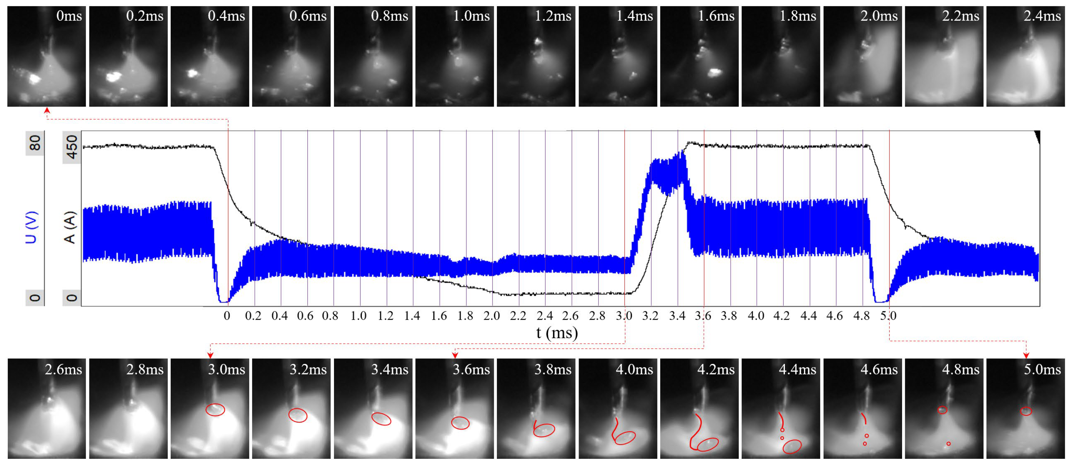
3.1.2. With 2.0 mm Oscillation Width

When the oscillation width is increased to 2.0 mm, an interesting phenomenon will occur. The arc will turn towards the sidewall with a small angle when the arc stops at the left or right dwell position. Figure 4a shows the arc shape in the left dwell position; it can be seen that the arc is turning with a small angle to the left sidewall rather than perpendicular to the bottom of the groove, and the discharge channel is partially established between the wire and the left sidewall. As a result, the sidewall can receive more heat input, which is important for improving sidewall penetration. In addition, the left side of the end of the wire melts faster than the other side. The same phenomenon occurs when the arc moves to the right dell position, as shown in Figure 4b.
Figure 5 displays the arc shape at different moments during the arc oscillating from the left to right dwell positions under an oscillation width of 2.0 mm. When the arc is in the left dwell position, due to the sidewall effect, the arc turns toward the left sidewall with a small angle, in 0 ms, as shown in Figure 5. As the welding arc oscillates to the right side, the influence of the left sidewall on the arc also decreases, and the inclination angle of the arc gradually disappears and changes to be perpendicular to the bottom of the narrow gap. The heat transmitted by the discharge channel also acts on the bottom of the groove, in 55 ms, as shown in Figure 5. As the arc continues oscillating to the right dwell position, the arc gradually turns toward the right sidewall. The shorter the distance from the arc to the sidewall, the greater the arc turning angle, with the angle reaching the maximum value when the arc reaches the right dwell position.
The arc length in different moments during the arc oscillating from the left to right dwell positions is shown in Figure 6. At 0 ms, the welding arc is at the left dwell position. Influenced by the sidewall of the groove, the arc length, h, is relatively short (2.1 mm). As the arc gradually moves to the right sidewall, h gradually increases and remains between 2.2 and 2.4 mm. At 109 ms, the arc oscillates to the right dwell position and h decreases to 2.1 mm due to the influence of the right sidewall. According to the above analysis, when the oscillating width is 2.0 mm, the arc length during the oscillating period does not change significantly, which indicates that the welding process is in a stable state.
The droplet transfer process and corresponding voltage and the arc’s electrical signal in the right dwell position under 2.0 mm oscillation width are shown in Figure 7. It can be seen that the welding arc is toward the right sidewall and the arc shape remains like a bell. The droplet transition process is consistent with the preset waveforms of the power supply, but what is different is that the droplet transition mode is no longer the ODOP mode. The moments from 3.8 to 4.2 ms in Figure 7 show that there is a liquid bridge between the droplet and the wire tip after the droplet detaches from the wire. When the droplet has fallen, the liquid bridge breaks into two parts; the upper part is pulled back to the wire tip by the surface tension and the lower part becomes several liquid drops and falls into the molten pool. The droplet transfer mode transforms to one-pulse multiple droplets, and the molten drop mode is a large drop with two small drops. The moment of 4.4 ms in Figure 7 shows that the droplet falls into the molten pool close to the sidewall, which is beneficial for improving sidewall penetration; the reason for this will be explained in the Section 4.

3.1.3. With 4.0 mm Oscillation Width

Increasing the oscillation width to 4.0 mm, the influence of the sidewall on the welding arc becomes more obvious, especially when the arc oscillates to the dwell position, where the arc will climb to the sidewall, which results from the arc being too close to the sidewall. With the arc climbing to the highest point, due to the principle of minimum voltage, the arc discharge channel will transfer from the bottom of the groove to the side-wall completely and form a stable discharge channel between the wire tip and the side-wall in 16.2 ms, as shown in Figure 8. The arc turns toward the sidewall at a small angle, and the discharge channel is mainly concentrated between the end of the wire and the bottom of the groove. At 56 ms, the arc discharge channel transfers to the sidewall. The discharge channel completes the transition from the bottom of the groove to the sidewall within 39.8 ms. According to the pre-set dwell time (77 ms), the arc is in an unstable state of adjusting the discharge channel in the first 39.8 ms; in the remaining 37.2 ms, the discharge channel is established between the end of the wire and the sidewall in 63.8 ms (as shown), which results in the heat transferred by the welding arc being absorbed and dis-tributed by the sidewall of the groove. Although the droplet eventually drops to the molten pool, the heat input transfer to the molten pool is greatly weakened, which leads to the rapid solidification of the molten pool, resulting in welding defects.
During the remaining 37.2 ms of dwell position welding, the droplet transfer is different, as shown in Figure 9. Because the discharge channel is built between the sidewall and the wire tip, the side of the wire close to the sidewall melts much more than the other side and gradually forms a droplet. During droplet growth, the arc occurs and biases to the sidewall, as shown from 3.0 to 3.8 ms in Figure 9. With the droplet detaching from the wire tip, a liquid metal bridge is formed between the droplet and the wire tip, as shown at 4.4 ms in Figure 9. The metal bridge connects the droplet to the wire under the action of surface tension, and the middle of the liquid bridge is bent toward the sidewall due to the action of the plasma drag force and the electromagnetic force. As the droplets continue to fall down, the liquid bridge is gradually elongated and presents an S-type shape, as shown from 4.4 to 5.2 ms in Figure 9. Finally, the liquid bridge cannot be maintained by surface tension and breaks into several small liquid balls and drops to the molten pool, so the droplet transfer mode transforms to one-pulse multiple droplets and the molten drop mode is a large drop with four small drops. Furthermore, as shown from 5.6 to 6.2 ms in Figure 9, the large droplets settle at the right side of the wire, rather than at the junction of the centerline of the wire and the weld pool surface. This further indicates that the placement of droplets cannot be effectively controlled, and it is not good for the control of weld bead forming.
In addition, the arc’s electrical signal waveforms show that the droplet transition process is inconsistent with the pre-set waveform. The expected droplet growth process is not seen in the pre-set Tb stage; instead, the multiple droplets detach from the wire and fall into the molten pool. In the pre-set TP stage, the droplet of the next cycle is generated rap-idly under the suddenly increased electrical parameters and grows in the pre-set Tf stage. Finally, the droplets fly into the molten pool in the next Tb stage. Through the above analysis, it can be seen that the actual droplet transition process does not conform to the pre-set waveforms, and it is adverse to the stability control of the welding process. Furthermore, the unstable droplet transition will also affect the waveform of the power source, as shown in the red circles in Figure 9, which undoubtedly further deteriorates the stability of the welding process.
The arc behaviors during oscillation are shown in Figure 10. At 0 ms, the wire is close to the left sidewall of the groove. Under the principle of minimum voltage, the discharge channel is established between the wire tip and the sidewall, and the arc is vertically stretched. With the arc moving away from the left sidewall, the discharge channel is transferred from the sidewall to the bottom of the groove and the arc length decreases. The arc oscillates to the right dwell position at 65 ms; under the principle of minimum voltage, the arc climbs from the bottom to the sidewall of the groove and establishes a stable dis-charge channel between the wire and the sidewall at 85 ms. This proves that the arc behaviors are always in a state of adjustment.
Figure 11 shows the change in the arc length in the process of the arc oscillating from the left to right dwell positions when the oscillating width is 4.0 mm. In t = 0 ms, the arc is in the left dwell position and arc length, h, is 5 mm. With the arc oscillating to the right sidewall, h gradually decreases and reaches a minimum value of 1.4 mm when the arc just reaches the right dwell position. Then, under the principle of minimum voltage, the arc climbs to the sidewall and h rises to 5.5 mm. It is confirmed that the arc length is in an unstable state under the 4.0 mm oscillation width, which is extremely harmful to the stability control of the welding process. All of the above analysis proves that excessive oscillation should be avoided in the welding process.

3.2. Effect on Weld Bead Formation

The oscillation process of the welding arc will affect the free surface morphology of the molten pool [39] and the heat distribution inside the molten pool [40], thus affecting the weld bead formation.
Figure 12a shows the weld bead formation and the macro-metallographic diagram of the weld cross-section under 4.0 mm oscillation width. Due to the excessive arc oscillation width, the sidewall of the groove is abraded by the welding arc (as shown by the yellow arrows), which easily leads to sidewall fusion defects in subsequent welding. The molten pool is expanded excessively by the oscillation arc, resulting in heat dissipation that is too fast, further leading to the gas inside the molten pool not completely overflowing the molten pool, with pores forming inside and on the surface of the molten pool (as shown by the red circles). Meanwhile, the molten pool solidifies and forms too quickly, resulting in obvious stacking traces on the surface of the weld bead. The tail of the weld pool presents a short and round shape, and the trailing angle, α, of the weld pool is large. The macro-metallographic metallographic diagram of the weld beads shows that the section morphology of the weld bead is irregular.
Reducing the arc oscillation width to 3.0 mm, the arc abrasion on the sidewall is improved significantly, as shown in Figure 12b. However, an undercut in the sidewall still exists (as shown in the red circles). Because of the narrower oscillation width, the molten pool temperature can maintain a relatively stable level, which results in smooth welding bead surface formation and no pore defects in the molten pool surface or cross-section of the weld bead. All of this verifies that the quality of the weld bead formation has significantly improved. The cross-section shows that the penetration depth (the definition of weld penetration measurement, as shown in Figure 12d) at the bottom of the weld bead increases and presents a “finger” shape. The same trend exists in the oscillation width of 2.0 mm, as shown in Figure 12c. However, there is no undercut in the weld bead.
Figure 12d shows the weld bead surface and cross-section appearance under the 1.0 mm arc oscillation width. The further reduced trailing angle, α, makes the molten pool look sharp and longer, and there is no undercut in the sidewall. The non-oscillation situation is shown in Figure 12e; as the molten pool accumulates in the middle of the groove, the temperature in the center of the molten pool rises. As a result, the molten pool spreads out in the welding direction of the groove. In addition, the heat input received by the sidewall decreases sharply because the molten pool stays in the middle of groove, and the metallographic of the cross-section shows that there is almost no sidewall penetration, which increases the risk of fusion defects in the sidewall. On the contrary, the accumulation of temperature results in an obvious formation of finger penetration at the bottom of the groove.
The weld penetration of the weld is shown in Figure 13. The sidewall penetration increases with an increase in oscillation width, which is consistent with the previous analysis of arc behavior. On the contrary, the bottom penetration decreases with the increase in oscillation width. In order to obtain both proper sidewall penetration and bottom penetration, a 2.0 mm oscillation width is recommended as a follow-up study.
Based on the above analysis of arc morphologies, droplet transition and weld bead forming quality under different oscillation widths, it is suggested that a 2.0 mm oscillation width is used for narrow-gap welding with the size shown in Figure 1a.

4. Discussion

Arc energy distribution has a significant effect on weld penetration depth and width. Chen et al. [41] found that the penetration and width of a weld is increased due to an increase in the arc energy in the pulsed ultrasonic-GMAW method. Zhu et al. [42] used the commercial CFD software Fluent to simulate the molten pool behaviors in the NG-GMAW of a 5083-Al alloy. The results showed that the arc pressure has a major effect on the weld bead surface shape, and the fluid flow pattern in the molten pool could change the sidewall penetration. During narrow-gap welding, the heat obtained by the base material, Q t o t a l , can be expressed in the following formula:
Q t o t a l = Q b + Q w = Q d r o p l e t + Q a r c
where Q b is the heat received by the bottom of the narrow gap, Q w is the heat received by the sidewall, Q d r o p l e t is the heat transmitted by the droplet and Q a r c is the heat transmitted by the arc. As shown in Figure 14a, during non-oscillation arc welding, the welding arc is perpendicular to the bottom, and the droplet flies into the molten pool under gravity, G , and the plasma flow force, F p ; all the heat transferred by the droplet and the arc acts on the bottom of the narrow gap. In the plane shown in Figure 14d, Q t o t a l is concentrated in the area with the width of L b on the bottom surface, with the heat transmitting to the bottom, Q b 0 , and this can be calculated using the following formula:
Q b 0 = Q t o t a l = Q d r o p l e t + Q a r c
As Q t o t a l concentrates at the bottom, heat spreads mainly in the vertical direction, which results in a finger-shaped fusion line, as shown in Figure 14d.
The varying arc shape in the narrow gap, with the increase in the oscillation width (from 0 to 3.0 mm), is shown in Figure 14b. Zhang G et al. [5] showed that the burning arc will automatically choose an appropriate current path to ensure the minimum value of the electrical field intensity in the arc column when the welding parameters and other conditions remain constant. Figure 14b illustrates that the horizontal distance of the wire tip to the right sidewall, d b , is shorter than the distance h. The electrical discharge channel will change from the bottom to the sidewall in maintaining a minimum arc voltage. Therefore, the arc inclines to the sidewall at γ °, and the effect area of the arc on the base metal is divided into two parts, as shown in Figure 14e: one is at the bottom of the narrow gap, and the other is on the sidewall. As a result, the plasma flow force F p , is applied towards to the sidewall with γ ° instead of consisting with gravity. Finally, the droplets fell into the molten pool closely to the sidewall, which is beneficial for improving sidewall penetration, leading to the following assumption:
L b = L b 1 + L w 1
The heat obtained by the bottom and the sidewall of the narrow gap can be approximated using the following formulas:
Q b 1 = Q d r o p l e t + Q a r c × L b 1 L b
Q w 1 = Q a r c × L w 1 L b
As L w 1 increases with the increase in γ ; the heat gained by the sidewall, Q w 1 , increases with an increase in the oscillation width, so the sidewall penetration increases correspondingly. On the contrary, L b 1 decreases with an increase in γ , so the heat obtained from the bottom, Q b 1 , of the narrow gap also decreases, and the penetration depth at the bottom also decreases accordingly. The fusion line shown in Figure 14e is like a bowl shape rather than a finger shape.
By continuously increasing the arc oscillation width, the arc climbs to a higher position under the action of the minimum voltage principle, as shown in Figure 14c. The electrical discharge channel is completely established between the wire tip and the sidewall, and the heat transmitted by the arc is concentrated in the area with the width of L w on the sidewall, as shown by the plane in Figure 14f. The heat received by the sidewall and the bottom of the narrow gap can be calculated using the following formulas:
Q w 2 = Q a r c
Q b 2 = Q d r o p l e t
As all the heat transmitted by the arc acts on the sidewall, and the metal at the bottom of the sidewall melts and breaks away from the sidewall under the action of the arc plasma flow force. Therefore, the molten pool only receives a small amount of heat transmitted by the droplets, which makes the molten pool unable to maintain a stable temperature and so it solidifies too quickly to form obvious stack traces. The plasma flow force, F p , is redirected away from the sidewall, as the dashed arrows show in Figure 14f, which leads the droplets to drop into the molten pool away from the sidewall.
As the Q a r c focuses on the sidewall, only Q d r o p l e t acts on the bottom; therefore, the fusion line shape is different and is mainly distributed in the sidewall area, as shown in Figure 14f.

5. Conclusions

A high-speed camera was used to record and analyze the arc shape and droplet transition of narrow-gap welding with different oscillation widths by using the vertical oscillation arc in P-GMA welding. The following conclusions have been drawn based on arc morphology, droplet transfer, weld bead formation and the macroscopic metallographic cross-section of the weld bead:
(1)
The welding process is stable when the oscillation width is appropriate, and the arc morphology is like a bell shape. When the arc oscillates in the dwell position, the arc will be inclined to the sidewall with a small angle due to the influence of the sidewall. However, an excessive oscillation width will result in the arc climbing to the sidewall, which makes the welding process unstable.
(2)
When the welding process is stable, the droplet transition process is consistent with the pre-set arc’s waveform. The droplet transition mode is ODOP when the arc is in the middle of the narrow gap but an MDOP mode when the arc oscillates to the dwell position, and the number of small droplets is increased when the oscillation width increases. In a narrow oscillation width sidewall dwell position, the droplet falls into the molten pool close to the sidewall due to the plasma flow force. However, in an excessive oscillation width condition, the plasma flow force is redirected by the sidewall, leading the droplet to fall into the molten pool away from the sidewall. In addition, the droplet transition process does not conform to the pre-set waveforms and also, in turn, affects the waveform of the power source, which undoubtedly further deteriorates the stability of the welding process.
(3)
The sidewall penetration increases with an increase in oscillation width; however, an oscillation width too wide will lead to defects such as porosity. On the contrary, the penetration depth of the groove bottom decreases with an increase in oscillation width, but an oscillation width too narrow will increase the risk of sidewall defects. The fusion line in the transection of the weld bead in non-oscillation welding presents a finger-type shape. With an increase in oscillation width, the appearance of the fusion line gradually changes to a bowl shape. The weld bead surface becomes smoother with a decrease in oscillation width to a certain extent.
(4)
The oscillation width has a major impact on the stability of the welding process when using a vertical oscillation arc welding X80 narrow-gap groove. Selecting the appropriate oscillation width can not only improve the appearance of the weld bead but also the sidewall fusion quality. A 2.0 mm oscillation width is suggested for narrow-gap welding with the size used in this paper.
In this paper, the influence of the oscillation width on the stability of vertical oscillation arc narrow-gap welding and the forming quality of the weld bead was analyzed. However, the mass and heat transfer of droplets and the welding arc to the molten pool and the molten pool flow behavior have a crucial impact on the formation of the weld bead. In addition, it is very important to analyze the distribution of the temperature field during the welding process by using the finite element model to control the sidewall penetration of the narrow gap, in order to further improve the understanding of the vertical oscillation arc narrow-gap welding mechanism and promote the application of this technology in the field of pressure vessels, such as pipe welding. Future work will focus on the abovementioned issues.

Author Contributions

Conceptualization, H.L. and J.Z.; methodology, R.X.; software, Y.B.; validation, H.L. and Y.X.; formal analysis, Y.X.; investigation, H.L.; resources, R.X.; data curation, H.L.; writing—original draft preparation, H.L.; writing—review and editing, R.X.; visualization, J.Z.; supervision, Y.X.; project administration, Y.B.; funding acquisition, R.X., Y.B. and J.Z. All authors have read and agreed to the published version of the manuscript.

Funding

This research was funded by the National Natural Science Foundation of Xinjiang, grant number 2022D01C391, the Science and Technology Innovations Project of the Outstanding Doctor of Xinjiang University, grant number XJUBSCX-201906, and Technology Innovation Team for Robots and Intelligent Equipment, grant number 2022D14002.

Data Availability Statement

The research is part of an ongoing project, so the supporting data are currently unavailable.

Acknowledgments

We sincerely thank York Technology Co., Ltd (Wayne, NJ, USA). for providing the high-speed cameras and laser light source equipment for this study free of charge.

Conflicts of Interest

The authors declare no conflict of interest.

References

  1. Wang, S. Research on Metal Transfer and Arc Behavior in Narrow Gap P-GMAW with Swing Arc. Master’s Thesis, Tianjin Polytechnic University, Tianjin, China, 2019. [Google Scholar]
  2. Qin, G. Development and application of narrow gap gas shielded welding process. Metalwork. Hot Work. 2022, 9, 8–20. [Google Scholar]
  3. Liu, G.; Tang, X.; Han, S.; Lu, F.; Cui, H. Influence of interwire angle on undercutting formation and arc behavior in pulsed tandem narrow-gap GMAW. Mater. Design 2020, 193, 1–14. [Google Scholar] [CrossRef]
  4. Wu, D.; Chen, Y.X.; Chen, H.B.; Chen, S.B. Influences of weaving parameters on dynamic characteristics and stability control of the droplet transfer in arc-weaving P-GMAW process. Int. J. Adv. Manuf. Technol. 2022, 119, 5233–5250. [Google Scholar] [CrossRef]
  5. Zhang, G.; Shi, Y.; Zhu, M.; Fan, D. Arc characteristics and metal transfer behavior in narrow gap gas metal arc welding process. J. Mater. Process. Technol. 2017, 245, 15–23. [Google Scholar] [CrossRef]
  6. Gu, Y.F.; He, G.Y.; Shi, G.; He, W.; Zhu, M. Detection and analysis of arc shape and droplet transfer behavior of narrow gap GMAW. J. Shanghai Jiao Tong Univ. 2016, 50, 1526–1529, 1534. [Google Scholar] [CrossRef]
  7. Sugitani, Y.; Kobayashi, Y.; Murayama, M. Development and application of automatic high speed rotation arc welding. Weld. Int. 1991, 5, 577–583. [Google Scholar] [CrossRef]
  8. Wang, J.Y.; Zhu, J.; Fu, P.; Su, R.J.; Han, W.; Yang, F. A swing arc system for narrow gap GMA welding. ISIJ Int. 2012, 52, 110–114. [Google Scholar] [CrossRef]
  9. Li, W.H.; He, C.F.; Chang, J.S.; Wang, J.Y.; Wu, J. Modeling of weld formation in variable groove narrow gap welding by rotating GMAW. J. Manuf. Process. 2020, 57, 163–173. [Google Scholar] [CrossRef]
  10. Guo, N.; Lin, S.B.; Zhang, L.; Yang, C.L. Metal transfer characteristics of rotating arc narrow gap horizontal GMAW. Sci. Technol. Weld. Joi 2009, 14, 760–764. [Google Scholar] [CrossRef]
  11. Guo, N.; Zhang, J.; Han, Y.; Zhang, L.; Yuan, X. Effects of Welding Parameters on Metal Transfer Process in Rotating Arc Narrow Gap Horizontal GMAW. Trans. Jwri. 2012, 2011, 5–7. [Google Scholar]
  12. Xu, W.H.; Lin, S.B.; Yang, C.L.; Fan, C.L. Study on droplet transfer of swing arc narrow gap GMAW, Trans. China Weld. Inst. 2017, 38, 109–114. [Google Scholar]
  13. Xu, W.H.; Fan, C.L.; Lin, S.B.; Yang, C.L. Research on droplet transfer in oscillating arc narrow gap GMA welding. Chin. Weld. 2014, 23, 12–16. [Google Scholar] [CrossRef]
  14. Xu, W.H. Research on Droplet Transfer and Welding Process of Oscillation arc Narrow Gap GMAW. Master’s Thesis, Harbin Institute of Technology, Harbin, China, 2014. [Google Scholar]
  15. Chen, Y.; Fang, C.F.; Yang, Z.D.; Wang, J.Y.; Xu, G.X.; Gu, X.Y. Cable-type welding wire arc welding. Int. J. Adv. Manuf. Technol. 2018, 94, 835–844. [Google Scholar] [CrossRef]
  16. Yang, Z.D.; Chen, Y.T.; Zhang, Z.W.; Fang, C.F.; Xu, K.; He, P.; Zhang, Z.D. Research on the sidewall penetration mechanisms of cable-type welding wire narrow gap GMAW process. Int. J. Adv. Manuf. Technol. 2022, 120, 2443–2455. [Google Scholar] [CrossRef]
  17. Lassaline, E.; Zajaczkowski, T.; North, T.H. Narrow Groove Twin-wire GMAW of High-strength Steel. Weld. J. 1989, 9, 53–58. [Google Scholar]
  18. Liu, L.M.; Hu, C.H.; Fang, D.S. Forming characteristics of narrow gap gas shielded three wire indirect arc welding. Trans. China Weld. Inst. 2018, 39, 119–123. [Google Scholar]
  19. Liu, L.M.; Wang, Z.L.; Zhang, T.Y.; Ba, X.L. Analysis of metal transfer and weld forming characteristics in triple-wire gas indirect arc welding. Int. J. Adv. Manuf. Technol. 2022, 120, 6777–6788. [Google Scholar] [CrossRef]
  20. Long, J.; Zhang, L.J.; Zhuang, M.X.; Bai, L.A.; Na, S.J. Narrow-gap laser welding with beam wobbling and filler wire and microstructural performance of joints of thick TC4 titanium alloy plates. Opt. Laser. Technol. 2022, 152, 1–20. [Google Scholar] [CrossRef]
  21. Shi, H.; Zhang, K.; Xu, Z.; Huang, T.Y.; Bao, W.N. Applying statistical models optimize the process of multi-pass narrow-gap laser welding with filler wire. Int. J. Adv. Manuf. Technol. 2014, 75, 279–291. [Google Scholar] [CrossRef]
  22. Yamazaki, Y.; Abe, Y.; Hioki, Y.; Nakatani, M.; Kitagawa, A.; Nakata, K. Fundamental Study of Narrow Gap Welding with Oscillation Laser Beam. Weld. Int. 2014, 30, 699–707. [Google Scholar] [CrossRef]
  23. Feng, J.C.; Rathod, D.W.; Roy, M.J.; Francis, J.A.; Guo, W.; Irvine, N.M.; Vasileiou, A.N.; Sun, Y.L.; Smith, M.C.; Li, L. An evaluation of multipass narrow gap laser welding as a candidate process for the manufacture of nuclear pressure vessels. Int. J. Pres. Ves. Pip. 2017, 157, 43–50. [Google Scholar] [CrossRef]
  24. Gong, M.C.; Kawahito, Y.; Li, G.; Gao, M.; Zeng, X.Y. Stabilization effect of space constraint in narrow gap laser-arc hybrid welding analyzed by approximate entropy. Int. J. Adv. Manuf. Technol. 2017, 92, 3093–3102. [Google Scholar] [CrossRef]
  25. Mirakhorli, F.; Cao, X.; Pham, X.-T.; Wanjara, P.; Fihey, J.-L. Technical Challenges in Narrow-Gap Root Pass Welding during Tandem and Hybrid Laser-Arc Welding of a Thick Martensitic Stainless Steel. Mater. Sci. Forum. 2016, 879, 1305–1310. [Google Scholar] [CrossRef]
  26. Meng, Y.F.; Li, G.; Gao, M.; Zhang, C.; Zeng, X.Y. Effects of groove parameters on space constraint of narrow gap laser-arc hybrid welding. J. Manuf. Process. 2018, 33, 144–149. [Google Scholar] [CrossRef]
  27. Yu, J.; Cai, C.; Xie, J.; Huang, J.S.; Liu, Y.H.; Chen, H. Weld formation, arc behavior, and droplet transfer in narrow-gap laser-arc hybrid welding of titanium alloy. J. Manuf. Process. 2023, 91, 44–52. [Google Scholar] [CrossRef]
  28. Cai, X.Y.; Lin, S.B.; Fan, C.L.; Yang, C.L.; Zhang, W.; Wang, Y.W. Molten pool behaviour and weld forming mechanism of tandem narrow gap vertical GMAW. Sci. Technol. Weld. Joi 2016, 21, 124–130. [Google Scholar] [CrossRef]
  29. Jones, L.A.; Eager, T.W.; Lang, J.H. A dynamic model of drops detaching from a gas metal arc welding electrode. J. Phys. D Appl. Phys. 1998, 31, 107–123. [Google Scholar] [CrossRef]
  30. Chen, Q.H.; Xie, Z.Y.; Wang, J.Y.; Lin, S.B.; Dou, Q.; Huang, T. A comparison of the swing and non-swing arc behavior in arc ultrasonic assisted narrow gap GMAW. JMRT 2023, 24, 4698–4710. [Google Scholar] [CrossRef]
  31. Song, X.P.; Li, Z.X.; Huang, J.K.; Fan, D.; Yu, S.R. Analysis of Droplet Transfer and Arc Swing in “TIG + AC” Twin-Wire Cross Arc Additive Manufacturing. Metals 2023, 13, 63. [Google Scholar] [CrossRef]
  32. Huang, J.; Chen, T.; Huang, D.Q.; Xu, T.Z. Study on the Effect of Pulse Waveform Parameters on Droplet Transition, Dynamic Behavior of Weld Pool, and Weld Microstructure in P-GMAW. Metals 2023, 13, 199. [Google Scholar] [CrossRef]
  33. Yang, Z.D.; Chen, Y.T.; Zhang, Y.S.; Fang, C.F.; Chen, S.J.; Gu, X.Y. Arc behavior and deposition characteristics of assisted wire filling cable-type welding wire GMAW. Int. J. Mod. Phys. B 2022, 36, 2240041. [Google Scholar] [CrossRef]
  34. Yang, Z.D.; Fang, C.F.; Chen, Y.; Liu, B.; Hu, Q.X.; Gu, X.Y. Effect of forces on dynamic metal transfer behavior of cable-type welding wire gas metal arc welding. Int. J. Adv. Manuf. Technol. 2022, 97, 81–90. [Google Scholar] [CrossRef]
  35. Casuso, M.; Veiga, F.; Suárez, A.; Bhujangrao, T.; Aldalur, E.; Artaza, T.; Amondarain, J.; Lamikiz, A. Model for the Prediction of Deformations in the Manufacture of Thin-Walled Parts by Wire Arc Additive Manufacturing Technology. Metals 2021, 11, 678. [Google Scholar] [CrossRef]
  36. Ding, J.; Colegrove, P.; Mehnen, J.; Ganguly, S.; Almeida, P.M.; Wang, F.; Williams, S. Thermo-mechanical analysis of Wire and Arc Additive Layer Manufacturing process on large multi-layer parts. Comput. Mater. Sci. 2011, 50, 3315–3322. [Google Scholar] [CrossRef]
  37. Liu, K.; Yan, Z.Y.; Wang, F.D.; Li, K.X.; Lin, S.B.; Chen, S.J. Microstructure, texture and mechanical properties of Inconel GH4169 superalloy fabricated by wire arc additive manufacturing with arc oscillation. J. Alloys Compd. 2023, 952, 170070. [Google Scholar] [CrossRef]
  38. Li, F.X.; Sun, Q.J.; Jin, P.; Liu, Y.B.; Chen, M.L.; Li, J.Z.; Hou, S.J.; Wang, M.X.; Ji, Y.Z. Wetting behavior of melt and its effect on lack of fusion in arc oscillating NG-GTAW. J. Mater. Process. Technol. 2021, 296, 117176. [Google Scholar] [CrossRef]
  39. Ebrahimi, A.; Kleijn, C.R.; Richardson, I.M. A simulation-based approach to characterize melt-pool oscillations during gas tungsten arc welding. Int. J. Heat. Mass. Tran. 2021, 164, 1–14. [Google Scholar] [CrossRef]
  40. Xu, G.X.; Wang, J.Y.; Li, P.F.; Zhu, J.; Cao, Q.N. Numerical analysis of heat transfer and fluid flow in swing arc narrow gap GMA welding. J. Mater. Process. Technol. 2018, 252, 260–269. [Google Scholar] [CrossRef]
  41. Chen, C.; Fan, C.L.; Cai, X.Y.; Lin, S.B.; Yang, C.L. Analysis of droplet transfer, weld formation and microstructure in Al-Cu alloy bead welding joint with pulsed ultrasonic-GMAW method. J. Mater. Process. Technol. 2019, 271, 144–151. [Google Scholar] [CrossRef]
  42. Zhu, C.X.; Cheon, J.; Tang, X.H.; Na, S.J.; Cui, H.C. Molten pool behaviors and their influences on welding defects in narrow gap GMAW of 5083 Al-alloy. Int. J. Heat Mass Transf. 2018, 126, 1206–1221. [Google Scholar] [CrossRef]
Figure 1. Schematic of the (a) vertical oscillation arc NG P-GMAW system, (b) welding arc trajectory in the narrow gap and (c) size of the narrow gap and specimens.
Metals 13 01057 g001
Figure 2. Schematic of the high-speed and data acquirement system.
Metals 13 01057 g002
Figure 3. Arc behaviors, droplet transfer process and corresponding arc’s electrical signal in non-oscillation.
Metals 13 01057 g003
Figure 4. Arc shape in the (a) left dwell position and (b) right dwell position with the 2.0 mm oscillation width.
Metals 13 01057 g004
Figure 5. Arc shape at different times with arc oscillating from left to right sidewall with 2.0 mm oscillation width.
Metals 13 01057 g005
Figure 6. Distance, h, from wire tips to bottom at different times during arc oscillating from left to right sidewalls with 2.0 mm oscillation width.
Metals 13 01057 g006
Figure 7. Arc behaviors, droplet transfer process and the corresponding arc’s electrical signal in the right dwell position under 2.0 mm oscillation width.
Metals 13 01057 g007
Figure 8. Arc behaviors during arc welding in the left dwell position with 4.0 mm oscillation width.
Metals 13 01057 g008
Figure 9. Arc behaviors, droplet transfer process and the corresponding arc’s electrical signal under 4.0 mm oscillation width.
Metals 13 01057 g009
Figure 10. Arc behaviors during arc oscillation with 4.0 mm oscillation width.
Metals 13 01057 g010
Figure 11. Distance, h, from the wire tips to the bottom in different moments during arc oscillating from left to right sidewalls with 4.0 mm oscillation width.
Metals 13 01057 g011
Figure 12. Weld bead formation in oscillation widths of (a) 4.0 mm, (b) 3.0 mm, (c) 2.0 mm, (d) 1.0 mm and (e) 0 mm.
Metals 13 01057 g012
Figure 13. Weld penetration with different oscillation widths.
Metals 13 01057 g013
Figure 14. Arc morphology under (a) non-oscillation, (b) 2 mm oscillation width and (c) 4 mm oscillation width, and schematic of arc and droplet transfer in NG P-GMAW under (d) non-oscillation, (e) 2 mm oscillation width and (f) 4 mm oscillation width.
Metals 13 01057 g014
Table 1. Chemical compositions of the base metal and filler wire (wt%).
MaterialCMnSiSPNiCuCrFe
Substrate0.0631.830.280.00060.0110.030.040.03Bal.
Wire0.081.370.590.0120.0120.0110.100.021Bal.
Disclaimer/Publisher’s Note: The statements, opinions and data contained in all publications are solely those of the individual author(s) and contributor(s) and not of MDPI and/or the editor(s). MDPI and/or the editor(s) disclaim responsibility for any injury to people or property resulting from any ideas, methods, instructions or products referred to in the content.

