Article

Comparative Assessment of Mechanical Properties and Fatigue Life of Conventional and Multistep Rolled Forged Connecting Rods of High Strength AISI/SAE 4140 Steel

1
Faculty of Engineering, Design and ICT, Bahrain Polytechnic, Isa Town P.O. Box 33349, Bahrain
2
Warwick Manufacturing Group, University of Warwick, Coventry CV4 7AL, UK
3
Department of Metallurgical and Materials Engineering (MME), Faculty of Chemical, Metallurgical & Polymer Engineering, University of Engineering and Technology (UET), Lahore 54890, Pakistan
*
Author to whom correspondence should be addressed.
Metals 2023, 13(6), 1035; https://doi.org/10.3390/met13061035
Submission received: 9 March 2023 / Revised: 21 April 2023 / Accepted: 4 May 2023 / Published: 28 May 2023

Abstract

:
This paper aims to improve the mechanical properties and fatigue life of AISI/SAE 4140 alloy steel connecting rods (CRs). Conventional CRs are typically manufactured through open die forging/hammering, blocking, and hot forging processes. In the present work, a modification to the process route has been proposed such that the open die forging/hammering was completely replaced with a multistep asymmetrical reducer rolling technique. Four rolling passes were introduced to achieve the desired preform shape and size. The effect of each rolling pass on grain size, mechanical properties, and fatigue life was investigated. Samples from each multistep rolling, blocking, and forging stage were subjected to impact, hardness, tensile, and fatigue testing. Metallography using optical and scanning electron microscopes was also conducted to reveal metallurgical changes. Fatigue testing and fractography were performed using the R.R. Moore Rotating-Beam Fatigue testing machine and scanning electron microscope, respectively, to evaluate the fatigue life and the fracture behavior of both the conventional and multistep rolled forged CRs. It was observed that, unlike the conventional forging process, multistep asymmetrical rolling gradually reduces grain size as the rolling progresses and improves yield, tensile, and impact strengths, hardness, and ductility. In comparison to conventional forging, multistep rolling led to an almost 33% and 29% increase in yield and tensile strengths, respectively. Moreover, the fatigue life of multistep rolled CR increased by more than five times compared to conventional CR.

1. Introduction

The existence of intense competition among automotive parts manufacturing industries and OEMs necessitates individual manufacturing units to reduce their production costs through advancements in the manufacturing setup. Forging produces uniform equiaxed grains and eliminates the defects present in casting and rolling, such as pin holes, blow holes, cavities, and pipes, thereby producing a very high strength and sound product [1,2,3,4]. Owing to this very reason, various high strength and precision parts of the automotive engine that are used in transmission and differential systems such as gears, pinions, drive shafts, crankshafts, connecting rods (CR), etc. are essentially manufactured by the hot forging technique. Thus, forged parts have a big market and demand all over the world, especially in the automotive, locomotive, aerospace, and defense industries [5,6].
Hot forging requires heating the stock to forging temperatures, which are typically in the range of 1100–1200 °C for plain carbon steels and 1150–1250 °C for low alloy and high strength steels. Although hot forging yields good strength and eliminates the rolling and casting defects due to the application of high temperature and compressive forces, it introduces its own defects such as overheating, folds, unfilling, excessive flash, mismatch, and cut marks [7,8,9]. Here, the mismatch and cut marks are considered to be the post forging defects due to die alignment and can, therefore, be avoided with relative ease [10,11]. However, the pre-forging defects, including overheating, folds, etc., need much attention at the stage of forging ‘preform’ manufacturing [12]. If the preform is not made properly, it will lead to defects and irrecoverable loss. Preform-making is normally done by an open die forging or hammering process which does not give an accurate preform for proper forging [13,14,15].
Simulation software and modeling tools help to analyze and optimize the production efficiency of automotive parts by comparing conventional manufacturing methods with newer, more efficient techniques [16,17,18]. Currently, high efficiency output may also be achieved by combining two or more bulk metal forming technologies that could yield a good quality product with better metallurgical and mechanical properties [12,19,20,21], as discussed in some recent studies.
Fuertes et al., 2016 used a severe plastic deformation (SPD) process in an isothermal forging process to refine the grain size up to 500 nm in aluminum alloys (AA1050 and AA5083) to achieve a 20% increase in hardness in connecting rods [16]. Kondaiah et al. (2018) studied effect of upsetting the forging and preform geometry process for the flashless P/M forging process of sintered AISI 4135 steel [22]. Edmond Ilia et al. (2019) used a power metallurgy (P/M) Fe–Cu–C alloy for hot forging connecting rods and found an increase in strength at 120 °C and 150 °C due to the formation of second phase precipitates due to the presence of Cu and the interaction of dislocations and copper-based precipitates [23]. Fengxian et al. (2020) investigated a flashless forging (P/M) route for manufacturing connecting rods, and focused on factors such as powder densification, isothermal compression, metal flow, and concluded using experiments and finite element modelling (FEM) simulations that preform geometry has a significant effect on the cracking and fracture behavior of P/M forged connecting rods [24]. Ning Zhao et al. (2022) showed that combining solution heat treatment (SHT) and a hot forging process as one operation supports improved mechanical properties by avoiding abnormal grain growth (AGG) along with a reduction in the production cost for hot forging of connecting rods using 6082 aluminum alloy [25]. The importance of ‘preform’ geometry and fine microstructure are main attributes towards producing quality within forging process for manufacturing connecting rods. However, processes such as severe plastic deformation (SPD) and power metallurgy (P/M) to achieve grain refinement and preform geometry mainly pose a challenge in high volume forging needs for automotive applications, especially in cases of high strength steel grades such 42CrMo4, AISI 4140, and AISI 4340, which are extensively used for forging engine and transmission parts.
Although various new techniques have been introduced in forging over the last few decades, such as incremental forging, flashless forging, precision forging, and roll forming, the idea of combining asymmetrical rolling with forging production lines still requires attention from engineers and researchers, as it offers great potential for improved production efficiency, waste minimization and green manufacturing. Thus, the hot rolling process to manufacture the semi-finished products can be exploited to replace the preforming, upsetting, and blocking processes, which are generally the prerequisites of forging.

2. Applications and Novelty

AISI/SAE 4140 steel is frequently used in many industrial applications due to its high strength, toughness, fatigue resistance, and wear resistance. It is used to manufacture automotive and railway parts, such as CRs, gears, shafts, piston rods, axles, etc. In the aerospace industry, it is used to make landing gear and engine components. In addition, it has found applications in the tool and die making and oil and gas industries, where it is used to manufacture the dies, molds, drill pipes, drill collars, and several other components.
In this study, a novel approach to manufacture an AISI/SAE 4140 steel CR is being presented to obtain customized improved mechanical properties using 4 pass multistep rolling (MSR), also called reducer rolling, followed by hot forging. Material properties were evaluated after each manufacturing step to identify their corresponding effect. A comparative analysis of the properties of a multistep rolled connecting rod (MSR-CR) with the conventional connecting rod (CCR) suggested that during preform manufacturing, the conventional hammering imparts poor metallurgical and mechanical properties relative to the asymmetrical reducer rolling.

3. Materials and Methods

AISI/SAE 4140 alloy steel, obtained from Peoples Steel Mills Limited, Karachi, Pakistan, was the material of choice to manufacture the CRs through conventional and MSR forging techniques. While the final forging step for each CR remained the same, the preforms for the blocking operation were prepared differently. The term ‘conventional’ implies that the preform was produced by traditional hammering, whereas the MSR refers to a 4-pass asymmetrically rolled preform. The chemical composition of the alloy in the hot rolled conditions was analyzed using spark emission spectroscopy (Foundry Master Smart-Hitachi), and is reported in Table 1 along with the standard composition.
Figure 1 schematically illustrates the key steps involved in the manufacture of MSR-CR. The AISI 4140 steel had an initial yield strength and a tensile strength of 415 MPa and 655 MPa, respectively, in the as-received annealed state. From an initial cylindrical block, a four-step reducer rolling technique was used to reduce the cross-section asymmetrically from the middle of the block such that the material is distributed unevenly along the longitudinal axis. This was followed by blocking and hot forging at a temperature of 1200 °C. Trimming was done to remove the flash material. Given that a total of six steps (four rolling + one blocking + one forging) were involved in the manufacture of MSR-CR, while standard samples for impact, hardness, tensile, and fatigue tests and metallography were prepared simultaneously using the same treatment as that experienced by the CR.

3.1. Metallography

As-received material was cut into the samples of size 10 × 10 × 30 mm3 using a precision diamond cutter of 0.3 µm to minimize mechanical damage. A cooling agent was utilized during cutting to avoid overheating and any significant metallurgical changes in the microstructure. An Olympus microscope (CK40 inverted) was used to view the microstructure at 100× magnification. The microscope was also equipped with DP21 and Olympus Stream Image analysis software for the grain size measurement. The intercept method was used from the image analyzer to determine the ASTM grain size number (n) as per standard ASTM E112 [26]. Note that the ASTM grain size number (n) can be calculated by counting the number of grains (N) using the equation N = 2 n 1 at a magnification of 100×. Samples from each stage, i.e., MSR, blocking and forging, were ground on 320 to 2500 grit size SiC abrasive papers with 50–100 N downward applied force, 150 rpm disc rotating speed, and water as the lubricating medium. Polishing was done with 9 µm, 6 µm and 1 µm diamond solution with 100 N applied force for 1 min. During the final polishing stage, OPS colloidal silica was used with 40 N force for 30 s. Samples were etched in 4% Nital solution (96% ethanol + 4% nitric acid) for microstructural examination.

3.2. Hardness Test

The Brinell hardness test was carried out according to the ASTM E10 standard [27]. Flat specimens of 100 mm thickness were taken from each manufacturing stage, including MSR, blocking and forging. A tungsten carbide ball with a diameter of 10 mm and a test force of 3000 kgf was applied on the flat surface of the samples after cleaning. The Brinell hardness number was calculated on an HBW 10/3000 scale by measuring the indent size diameters under the microscope using Equation (1):
H B W = 2 F π D D D 2 d 2
where, F is the test force in kgf, D is the diameter of the indenter ball in mm, and d is the measured mean indentation diameter in mm.

3.3. Tensile Test

The ASTM A370 standard was used to perform tensile tests on a 1000 kN Shimadzu Universal Testing Machine [28,29]. Dumbbell-shaped samples were taken from the product of each rolling, blocking and forging stage. The samples were accurately machined to the required dimensions on a CNC turning machine. An external extensometer was mounted within the gauge length to measure the percentage elongation during the test. The tests were conducted in the displacement-controlled mode at a fixed strain rate of 0.001 s–1.

3.4. Impact Test

The impact test was realized on a ZwickRoell Pendulum Impact Tester in accordance with the ASTM A370 standard. Square-shaped samples with a cross-section of 10 mm × 10 mm were obtained from each manufacturing stage and prepared on a CNC milling machine [28]. A 45º V-notch with a depth of 2 mm was machined at the mid-length across the specimen on one of the faces. The samples were then mounted in the impact tester and subjected to impact loading through a swinging hammer at a temperature of 25 °C and a humidity level of 46%.

3.5. Fatigue Test

An R.R. Moore Rotating-Beam Fatigue testing machine was employed to determine the total number of cycles to failure under fatigue loading and given stress level. The fatigue test was performed on the samples obtained from the end-product, i.e., CCR and MSR-CR. Straight shank type specimens with a total length of 110 mm including a tapered length of 30 mm and a minimum diameter of 6 mm at the middle of the specimen were used and held in the machine with the help of precision specimen collets. Each test was repeated three times, and the average values were reported. Deadweights of predetermined loads were applied to achieve the desired level of stress. Although the rotating-beam fatigue test can be exploited to obtain the so-called ‘S-N curves’ at various stress levels, only a single stress level of 300 MPa at a rotation speed of 2800 rpm was investigated in this work, since the objective was to draw a comparison between the fatigue lives of the CRs and reveal the fracture morphology of each specimen.

3.6. Scanning Electron Microscopy

The fractured surfaces of conventional and MSR forged CRs were analyzed using a Nova NanoSEM 450 scanning electron microscope (SEM). The surface morphology was revealed under high vacuum conditions at an acceleration voltage of 25 kV with a secondary electron detector. A comparison of the fracture behaviors is presented in the subsequent section.

4. Results and Discussion

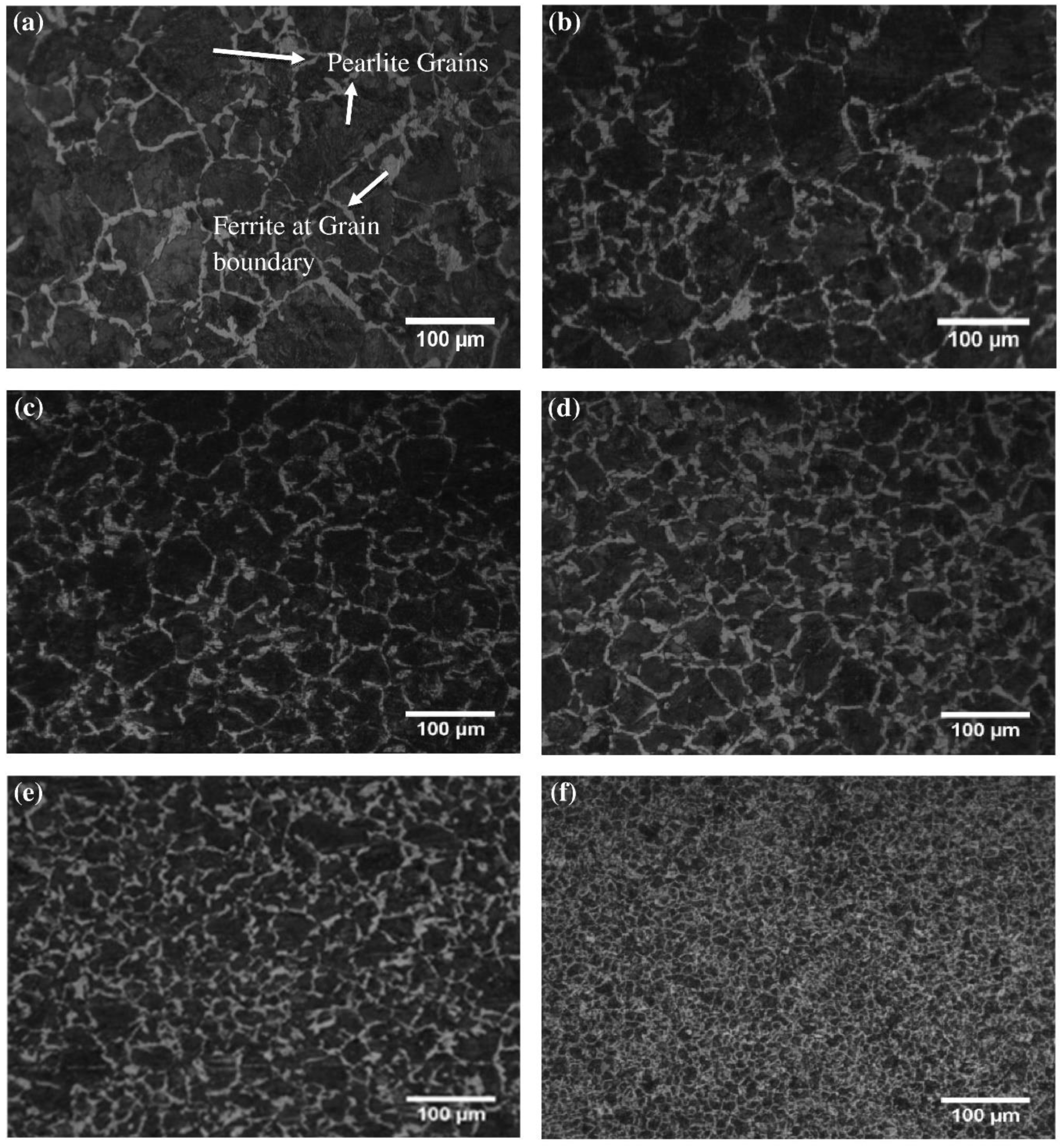
4.1. Grain Size Evolution

Grain size is known to have a profound effect on the mechanical properties of polycrystalline metals and alloys. Thus, the grain refinement is usually performed to improve several properties, including tensile strength, yield strength, and hardness [30,31,32]. In this study, the raw material in the as-received state had an initial ASTM grain size number (n) of approximately 2, which corresponds to an average grain diameter (d) of ~180 µm according to the relation, d = 254 / 2 n 1 .
Figure 2 illustrates the gradual refinement of grain size at the end of each rolling, blocking and forging step. A change in ASTM grain size number from 3 to 7 was observed at the end of MSR, while blocking and forging further refined it to 9. Note that the ASTM grain size in the CCR was found to be approximately 4.5, i.e., d = 75.5 µm. It was also noticed that instead of showing elongated grains, the microstructures after each rolling step (Figure 2a–d) illustrated finer yet equiaxed grains because they were all taken in the direction transverse to the rolling direction. This was important for two reasons. First, the blocking and the forging produce equiaxed grains and, hence, the comparison of the grain refinement with the elongated grains along the rolling direction would be meaningless. Second, the change in strength as a function of the grain refinement could be established.
Table 2 presents the average grain diameter (d) corresponding to each ASTM grain size number (n) for the MSR forged CR. Since the average grain diameter (d) decreases by a factor of more than 10, a considerable increase in strength values is expected. It may also be observed that the final grain size of the MSR-CR (d = 15.9 µm) is almost five times finer than that of the CCR. This clearly indicates that the mechanical properties of the former would be significantly improved as compared to the latter.
Furthermore, MSR offers repeatability and control over the preform manufacturing process and maintains the forging temperature, which provides metallurgical benefits, such as grain refinement and improvement in mechanical properties in CR manufacturing. The hammering process has no control over the geometry and results in a decrease in temperature during forging operations. This leads to die wear and poor mechanical properties of the CR.

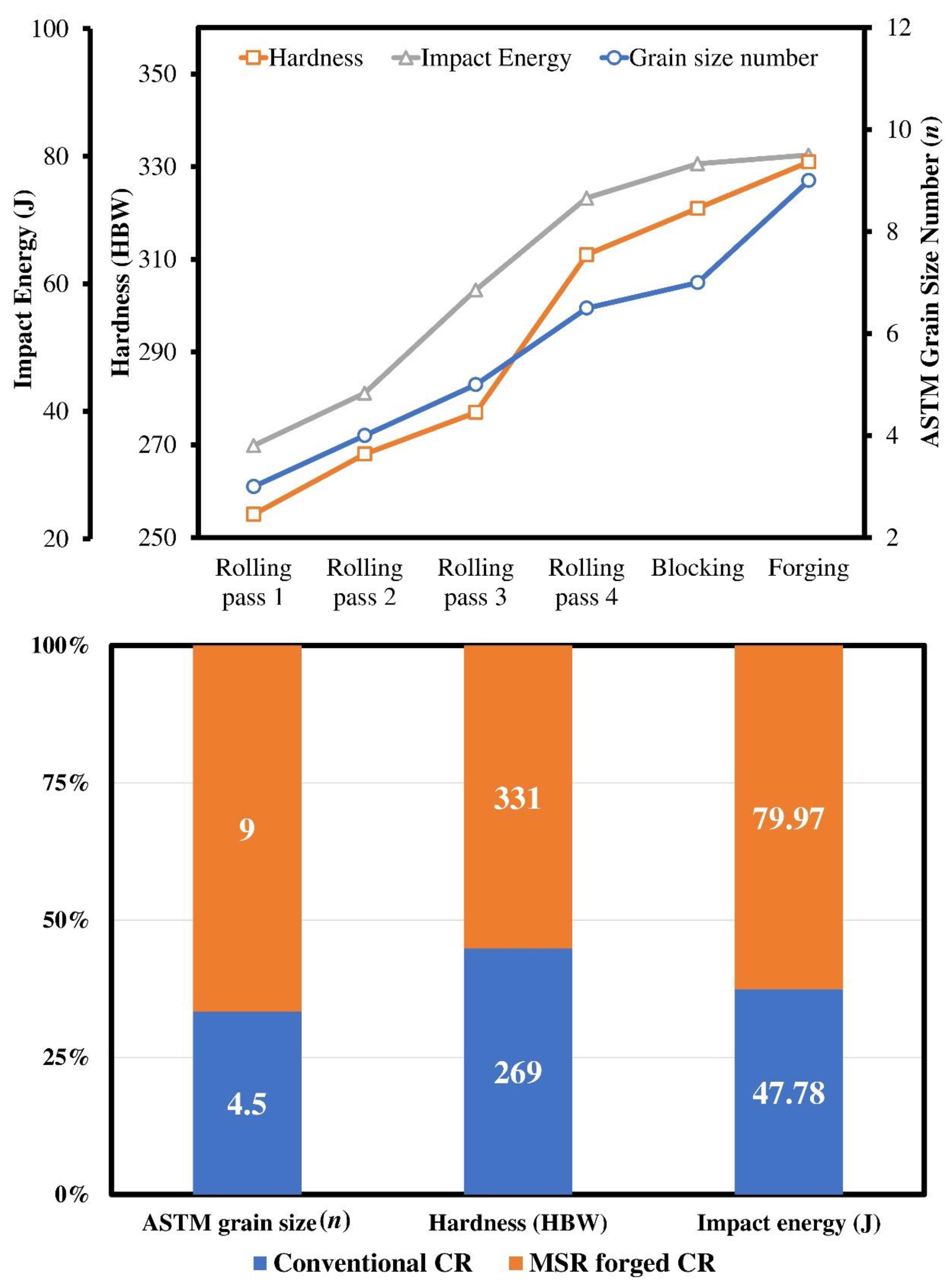
4.2. Effect on Hardness and Impact Strength

It is evident that the mechanical properties such as hardness and strength will increase as a result of repeated work hardening in the MSR-CR; however, the aim here is to quantify the effect relative to the CCR.
Figure 3 demonstrates the effect of each manufacturing step on the ASTM grain size, Brinell hardness (HBW), and impact energy. Note that the hardness of the MSR-CR increases from 255 HBW to 331 HBW, i.e., by more than 30%. In the CCR, however, the hardness reaches a maximum value of 269 HBW, which is 20% less than that of the MSR-CR. A 20% increase in hardness is already a considerable improvement from the product design perspective. Similarly, an increase in the impact energy is even more significant for the MSR-CR as it doubles from 34 J to 80 J during manufacturing. Compared to CCR’s nearly 48 J, the MSR-CR shows 60% more impact energy absorption due to noticeable grain refinement from n = 4.5 for the former to n = 9 for the latter. In addition to the improvement in mechanical properties, the appearance of brittle behavior in the metal and alloys is quite common, which can also be evaluated through impact testing. It is expected that brittle failure would result in relatively less absorption of impact energy than ductile fracture.
Figure 4 shows the fractured impact test samples at each stage of the MSR forged CR and SEM images of fractured surfaces after rolling stage-1 and forging. Note that a given specimen after the first rolling shows a brittle fracture with sharp facets and a negligible change in the cross-section, whereas at the end of the MSR, blocking and forging stages, it depicts a highly ductile fracture with observable necking over the cross-section of the fractured surface. It is also worthy of note that not only does the transition from brittle to ductile behavior increase gradually with increasing work hardening, but the impact energy values also follow the same trend. A possible reason for this behavior is that the dispersion of the inclusions and refinement of the grain size promote ductility in polycrystalline materials [33,34,35,36,37].

4.3. Tensile Test Properties

The variation in grain size affects the mechanical properties which can be explained on the basis of plasticity theory. Since the ‘flow’ of dislocations is more restricted in a fine-grained structure, a higher yield and tensile strength should be expected in the MSR-CR. The mathematical relation of the grain size with yield strength is given by the Hall-Petch Equation [38,39]
σ y = σ 0 + k y d
where, σ y is the yield strength of the polycrystalline material in MPa, d is the average grain diameter in µm, σ 0 is a material constant in MPa also known as friction stress, i.e., the stress required for dislocation movement in a particular material, and k y is a strain-dependent Hall-Petch material strengthening coefficient in MPa.µm1/2.
Figure 5 compares the change in tensile and yield strengths and % elongation during the manufacturing of MSR-CR. A comparison between CCR and MSR-CR is also presented in the figure. Note that during the initial stages of work hardening, i.e., rolling passes 1 and 2, there is a rapid increase in both the yield and tensile strength values. However, from rolling pass 2 onwards, the slope of both the curves decreases. This is a typical behavior of any work hardening metallic material. Although grain size refinement was almost linear until the final production of MSR-CR, the work hardening saturation was observed quite early. For instance, the increase in the yield strength from the first to second rolling pass was almost 300 MPa (~704 MPa–406 MPa), which amounts to approximately two times (1.73 = 704/406). However, the same is around 20 MPa (~893 MPa–873 MPa) between the blocking and forging processes. An identical pattern was followed by the tensile strength values. This points towards a very important finding, as although MSR helps to obtain a relatively stronger CR, an increase in the number of rolling passes without quantifying the effect of each upon mechanical property can only be an added production cost with little or no improvement in the overall properties.
Unlike the 60% increase in the impact energy absorption of MSR-CR compared to CCR, an increase of only 30% in tensile and yield strengths was observed for the former compared to the latter. This is interesting, as CRs are almost equally subjected to impact and tensile loadings. Hence, even if there is not a considerable increase in tensile strength, increasing the number of manufacturing steps can still be beneficial in improving other properties of the material, such as impact strength. Ductility, for example, is another property that showed a linear increase as a function of work hardening (see the % elongation curve in Figure 5 and the elongated fractured tensile test specimens in Figure 6). All of the specimens reveal substantial necking, which is evidence of significant plastic deformation, in addition to percentage elongation. Increased plastic deformation coupled with high strength gives rise to the high toughness in the material. Note that ductility is the only mechanical property that, compared to CCR (elongation = 9%), doubled in MSR-CR (elongation = 17%). This implies that a combination of different properties is achievable using the modified CR production route. However, this warrants an optimum selection of several parameters, including the number of rolling passes, the reduction ratio while rolling, rolling and forging temperatures, etc., which would be dependent upon the type of metallic material and the final geometry of the end product.

4.4. Fatigue Life

Improvement in fatigue life by the grain refinement in different steels, including S20C, has been reported in the literature [40,41,42]. It has been proposed that a direct relation exists among the average grain diameter, ultimate tensile strength, and the fatigue life of steels [40]. Figure 7 compares the total number of cycles which both the samples of CCR and MSR-CR could withstand until failure at a completely reversed fatigue load of 300 MPa, applied using an R.R Moore type machine. It also presents a relative difference between the grain size, ductility, and tensile strength of both CRs. Note that the MSR-CR and CCR fail after 1.1 and 0.19 million cycles, respectively. This implies that under the given loading conditions, MSR yields an increase in the fatigue life of CR by a factor of more than five, although there is still a need to evaluate the fatigue life at other loads. Nevertheless, an improvement in fatigue life may be attributed to a combination of fine grain size, increased tensile, impact and yield strengths, and ductility.
Fatigue failure is typically characterized by three distinct regions, namely, the regions of crack initiation, propagation, and catastrophic failure. Figure 8 shows SEM images taken from all three regions of the fractured samples representing both the CCR and MSR-CR. Here, the term representative fatigue sample implies that the samples were given the same thermo-mechanical treatment as experienced by their corresponding CRs. Note that both the samples exhibit significant propagation of the crack before resulting in a catastrophic failure. Moreover, a reduction in the cross-section area at the fracture location indicates noticeable necking before failure. It should be pointed out that the regions of catastrophic failure/brittle fracture are marked in both the images of the broken specimens with a dashed circle. It may be observed that this region is larger in the CCR sample than in the MSR-CR sample. This finding is coherent with the grain size observation and the mechanical test results summarized in Figure 7. The fact that the CCR sample possessed lesser ductility and less strength due to coarse grain size led to its brittle catastrophic failure as soon as the surface and/or the sub-surface cracks began. There is hardly any noticeable region of crack propagation. Figure 8 also shows the presence of a subsurface crack in the CCR sample, which is highlighted with the help of an arrow.
On the contrary, the MSR-CR sample illustrates not only a smaller region of catastrophic failure, but also a sizeable region of crack propagation showing beach marks (see the MSR-CR sample at 200 µm in Figure 8). This is typical behavior of a ductile sample, since the material has a higher tendency to fracture in a cup-cone failure mode after neck formation. Moreover, there is no evidence of subsurface crack generation or propagation, and, hence, the sample surface is the only favorable site for crack initiation. These observations are also supported by the previous findings of the very high ductility and strength of MSR-CR, as shown in Figure 7.

5. Conclusions

From the above investigation, the following conclusions can be drawn.
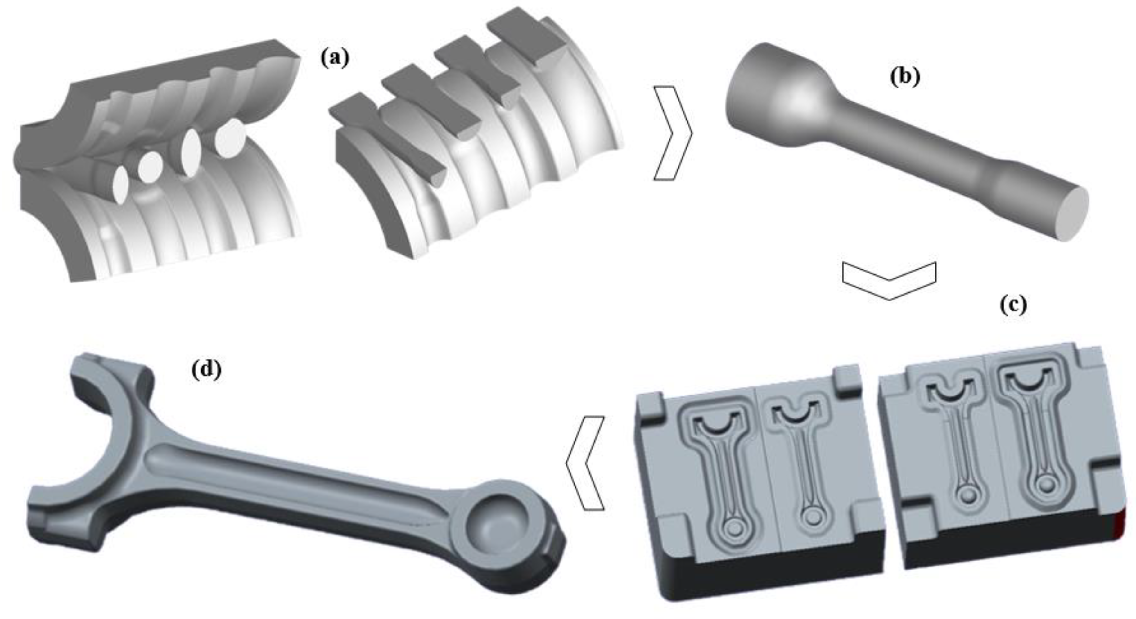
  • The MSR compared to hammering /open die forging is a repeatable process, and allows more control not only over the preform geometry, but also upon the desired level of grain refinement. By adjusting the rolling parameters such as the reduction ratio and the number of passes, etc., a desired grain size, and hence, the desired properties may be achieved in the final product.
  • A combined effect of an increase in hardness, tensile strength, impact strength, and ductility substantially improved the fatigue life of the component. Hence, compared to CCR, the MSR-CR resulted in a more than five-fold increase in fatigue life for the given loading conditions, which is of great practical importance.
Although the anisotropy due to the elongation of grains along the rolling direction may be regarded as a limitation of MSR, which is certainly not the case in hammering, the recrystallization expected at forging temperatures is likely to minimize the effect by introducing new strain-free finer grains. The anisotropic aspect, however, requires further investigation. Similarly, the effect of finer grains on heat treatment and martensite formation also needs further study.

Author Contributions

Conceptualization: Q.H., F.A.; Supervision: F.A.; Methodology: Q.H., M.A.; Data curation: Q.H., M.A.; Investigation: W.A.K., Q.H., F.A., M.A., M.Z.-u.-A.; Validation: W.A.K., M.Z.-u.-A.; Formal analysis: Q.H., F.A.; Writing—Original draft: Q.H., M.Z.-u.-A.; Writing—review and editing: W.A.K., F.A., M.A., M.Z.-u.-A.; Funding acquisition: W.A.K. All authors have read and agreed to the published version of the manuscript.

Funding

The APC was funded by Bahrain Polytechnic, Isa Town PO Box 33349, Bahrain under grant reference number AREC/2023/007.

Institutional Review Board Statement

Not applicable.

Informed Consent Statement

Not applicable.

Data Availability Statement

Not applicable.

Conflicts of Interest

The authors declare that they have no conflict of interest.

References

  1. Wang, Q.; He, F. A review of developments in the forging of connecting rods in China. J. Mater. Process. Technol. 2004, 151, 192–195. [Google Scholar] [CrossRef]
  2. Jahazi, M.; Eghbali, B. The influence of hot forging conditions on the microstructure and mechanical properties of two microalloyed steels. J. Mater. Process. Technol. 2001, 113, 594–598. [Google Scholar] [CrossRef]
  3. Dornfeld, D.; Yuan, C.; Diaz, N.; Zhang, T.; Vijayaraghavan, A. Introduction to green manufacturing. In Green Manufacturing: Fundamentals and Applications; Springer: Boston, MA, USA, 2013; pp. 1–23. [Google Scholar]
  4. Altan, T.; Ngaile, G.; Shen, G. Cold and Hot Forging: Fundamentals and Applications; ASM International: Almere, The Netherlands, 2005; Volume 1. [Google Scholar]
  5. Takemasu, T.; Vazquez, V.; Painter, B.; Altan, T. Investigation of metal flow and preform optimization in flashless forging of a connecting rod. J. Mater. Process. Technol. 1996, 59, 95–105. [Google Scholar] [CrossRef]
  6. Hawryluk, M.; Jakubik, J. Analysis of forging defects for selected industrial die forging processes. Eng. Fail. Anal. 2016, 59, 396–409. [Google Scholar] [CrossRef]
  7. Hosford, W.F.; Caddell, R.M. Metal Forming: Mechanics and Metallurgy; Cambridge University Press: Cambridge, UK, 2011. [Google Scholar]
  8. Baban Jadhav, V.; Kumar Jain, A.; Khan, A. Optimizing production of hot forging process with waste control and die life improvement. Mater. Today Proc. 2023; in press. [Google Scholar] [CrossRef]
  9. Bauccio, M. ASM Metals Reference Book; ASM International: Almere, The Netherlands, 1993. [Google Scholar]
  10. Tanner, J.P.; Engineering, M. An Introduction to the Basic Functions, Revised and Expanded; CRC Press: Boca Raton, FL, USA, 1990; Volume 36. [Google Scholar]
  11. Weng, G. A micromechanical theory of grain-size dependence in metal plasticity. J. Mech. Phys. Solids 1983, 31, 193–203. [Google Scholar] [CrossRef]
  12. Sezen, B.; Çankaya, S.Y. Effects of green manufacturing and eco-innovation on sustainability preformance. Procedia-Soc. Behav. Sci. 2013, 99, 154–163. [Google Scholar] [CrossRef]
  13. Valiev, R.; Alexandrov, I.; Zhu, Y.; Lowe, T. Paradox of strength and ductility in metals processed bysevere plastic deformation. J. Mater. Res. 2002, 17, 5–8. [Google Scholar] [CrossRef]
  14. Arzt, E. Size effects in materials due to microstructural and dimensional constraints: A comparative review. Acta Mater. 1998, 46, 5611–5626. [Google Scholar] [CrossRef]
  15. Xiong, M.-X.; Liew, J.R. Mechanical properties of heat-treated high tensile structural steel at elevated temperatures. Thin-Walled Struct. 2016, 98, 169–176. [Google Scholar] [CrossRef]
  16. Fuertes, J.P.; Luis, C.J.; Luri, R.; Salcedo, D.; León, J.; Puertas, I. Design, simulation and manufacturing of a connecting rod from ultra-fine grained material and isothermal forging. J. Manuf. Process. 2016, 21, 56–68. [Google Scholar] [CrossRef]
  17. Lu, Y.; Peer, A.; Abke, T.; Kimchi, M.; Zhang, W. Subcritical heat affected zone softening in hot-stamped boron steel during resistance spot welding. Mater. Des. 2018, 155, 170–184. [Google Scholar] [CrossRef]
  18. Bramley, A.N.; Mynors, D. The use of forging simulation tools. Mater. Des. 2000, 21, 279–286. [Google Scholar] [CrossRef]
  19. Kalpakjian, S.; Schmid, S.R.; Musa, H. Manufacturing Engineering and Technology: Machining; China Machine Press: Beijing, China, 2011. [Google Scholar]
  20. Rahmati, S.; Rezaei, M.R.; Akbari, J. Design and manufacture of a wax injection tool for investment casting using rapid tooling. Tsinghua Sci. Technol. 2009, 14, 108–115. [Google Scholar] [CrossRef]
  21. Chryssolouris, G. Manufacturing Systems: Theory and Practice; Springer Science & Business Media: Berlin/Heidelberg, Germany, 2013. [Google Scholar]
  22. Kondaiah, E.V.; Kumaran, S.; Sundarrajan, S. Study on densification behaviour of sintered AISI 4135 steel through hot upset forging. Mater. Today Proc. 2018, 5, 6543–6549. [Google Scholar] [CrossRef]
  23. Ascari, A.; Fortunato, A. Laser Dissimilar Welding of Highly Reflective Materials for E-Mobility Applications, 1st ed.; Elsevier Ltd.: Amsterdam, The Netherlands, 2021. [Google Scholar] [CrossRef]
  24. Li, F.; Chen, P.; Han, J.; Deng, L.; Yi, J.; Liu, Y.; Eckert, J. Metal flow behavior of P/M connecting rod preform in flashless forging based on isothermal compression and numerical simulation. J. Mater. Res. Technol. 2020, 9, 1200–1209. [Google Scholar] [CrossRef]
  25. Zhao, N.; Ma, H.; Sun, Q.; Hu, Z.; Yan, Y.; Chen, T.; Hua, L. Microstructural evolutions and mechanical properties of 6082 aluminum alloy part produced by a solution-forging integrated process. J. Mater. Process. Technol. 2022, 308, 117715. [Google Scholar] [CrossRef]
  26. ASTM E112-10; Standard Test Methods for Determining Average Grain Size. ASTM International: West Conshohocken, PA, USA, 2010; Volume 13, No. Reapproved. pp. 1–27. [CrossRef]
  27. ASTM E10-18; Brinell Hardness of Metallic Materials: Standard Test Method for Brinell Hardness of Metallic Materials. Am. Assoc. State Highw. Transp. Off. Stand. AASHTO. No. T70-86; ASTM International: West Conshohocken, PA, USA, 2015; pp. 1–32. [CrossRef]
  28. ASTM A370; Standard Test Methods and Definitions for Mechanical Testing of Steel Products. ASTM International: West Conshohocken, PA, USA, 2014; pp. 1–50.
  29. ASTM E8/E8M; Standard Test Methods for Tension Testing of Metallic Materials 1. Annu. B. ASTM Stand. 4, no. C; ASTM International: West Conshohocken, PA, USA, 2010; pp. 1–27.
  30. Ijaz, H.; Zain-ul-Abdein, M.; Saleem, W.; Asad, M.; Mabrouki, T. Numerical simulation of the effects of elastic anisotropy and grain size upon the machining of AA2024. Mach. Sci. Technol. 2018, 22, 522–542. [Google Scholar] [CrossRef]
  31. Wang, Y.; Chen, M.; Zhou, F.; Ma, E. High tensile ductility in a nanostructured metal. Nature 2002, 419, 912–915. [Google Scholar] [CrossRef]
  32. Marchi, C.S.; Somerday, B.; Tang, X.; Schiroky, G. Effects of alloy composition and strain hardening on tensile fracture of hydrogen-precharged type 316 stainless steels. Int. J. Hydrogen Energy 2008, 33, 889–904. [Google Scholar]
  33. Fujita, H.; Tabata, T. The effect of grain size and deformation sub-structure on mechanical properties of polycrystalline aluminum. Acta Metall. 1973, 21, 355–365. [Google Scholar] [CrossRef]
  34. Ijaz, H.; Zain-ul-Abdein, M.; Saleem, W.; Asad, M.; Mabrouki, T. Modified Johnson-Cook Plasticity Model with Damage Evolution: Application to Turning Simulation of 2XXX Aluminium Alloy. J. Mech. 2017, 33, 777–788. [Google Scholar] [CrossRef]
  35. Gao, S.; Li, Y.; Yang, L.; Qiu, W. Microstructure and mechanical properties of laser-welded dissimilar DP780 and DP980 high-strength steel joints. Mater. Sci. Eng. A 2018, 720, 117–129. [Google Scholar] [CrossRef]
  36. Calcagnotto, M.; Ponge, D.; Raabe, D. Effect of grain refinement to 1μm on strength and toughness of dual-phase steels. Mater. Sci. Eng. A 2010, 527, 7832–7840. [Google Scholar] [CrossRef]
  37. Farhat, Z.; Ding, Y.; Northwood, D.; Alpas, A. Effect of grain size on friction and wear of nanocrystalline aluminum. Mater. Sci. Eng. A 1996, 206, 302–313. [Google Scholar] [CrossRef]
  38. Dieter, G.E.; Kuhn, H.A.; Semiatin, S.L. Handbook of Workability and Process Design; ASM International: Almere, The Netherlands, 2003. [Google Scholar]
  39. Armstrong, R.W. Engineering science aspects of the Hall--Petch relation. Acta Mech. 2014, 225, 1013–1028. [Google Scholar] [CrossRef]
  40. Taira, S.; Tanaka, K.; Hoshina, H. Fatigue Mechanisms. In Proceedings of the ASTM-NBS-NSF Symposium, Kansas City, MO, USA, 21–22 May 1978; Fong, J.T., Ed.; American Society for Testing and Materials: West Conshohocken, PA, USA, 1978; pp. 135–173. [Google Scholar]
  41. Saini, N.; Pandey, C.; Mahapatra, M.; Narang, H.; Mulik, R.; Kumar, P. A comparative study of ductile-brittle transition behavior and fractography of P91 and P92 steel. Eng. Fail. Anal. 2017, 81, 245–253. [Google Scholar] [CrossRef]
  42. Pandey, C.; Saini, N.; Mahapatra, M.; Kumar, P. Study of the fracture surface morphology of impact and tensile tested cast and forged (C&F) Grade 91 steel at room temperature for different heat treatment regimes. Eng. Fail. Anal. 2017, 71, 131–147. [Google Scholar] [CrossRef]
Figure 1. Fabrication process sequence. (a) Multistep rolling, (b) Rolled Preform. (c) Closed die forging, and (d) Finished MSR-CR.
Metals 13 01035 g001
Figure 2. Microstructure of AISI/SAE 4140 steel illustrating grain refinement from (af); images were taken after (a) Rolling pass 1, (b) Rolling pass 2, (c) Rolling pass 3, (d) Rolling pass 4, (e) blocking and (f) forging.
Metals 13 01035 g002
Figure 3. Evolution and comparison of grain size, hardness and impact energy of CCR and MSR-CR.
Metals 13 01035 g003
Figure 4. Fracture morphology of impact test specimen during MSR, blocking and forging.
Metals 13 01035 g004
Figure 5. Evolution and comparison of tensile and yield strengths, and % elongation of CCR and MSR-CR.
Metals 13 01035 g005
Figure 6. Fractured tensile test specimen after each MSR, blocking and forging stage.
Metals 13 01035 g006
Figure 7. Comparison of number of cycles (fatigue-life), % elongation, grain size, and tensile strength between CCR and MSR-CR.
Metals 13 01035 g007
Figure 8. Fracture Surface after fatigue failure: SEM images of samples representing (a) CCR, and (b) MSR-CR; dashed circles are the regions of catastrophic failure/brittle fracture.
Metals 13 01035 g008
Table 1. Standard composition according to the Society of Automotive Engineers & Spectroscopy analysis of AISI/SAE 4140 and as-received raw material.
Sample (wt. %)CSiSPMnCrCuNiMo
Standard0.38 ~0.430.15 ~0.350.05 max0.03 max0.75~1.000.80~1.10.30 max0.25 max0.15 ~0.25
Actual0.410.300.0080.00250.780.910.240.110.20
Table 2. ASTM grain size number (n) and corresponding average grain diameter (d) for an MSR forged connecting rod.
StageInitial
(as-Received)
Asymmetric Rolling PassBlockingForging
1234
n23456.579
d (µm)179.6127.089.863.537.831.815.9
Disclaimer/Publisher’s Note: The statements, opinions and data contained in all publications are solely those of the individual author(s) and contributor(s) and not of MDPI and/or the editor(s). MDPI and/or the editor(s) disclaim responsibility for any injury to people or property resulting from any ideas, methods, instructions or products referred to in the content.

