Article

Optimization of Process Parameters of Fused Filament Fabrication of Polylactic Acid Composites Reinforced by Aluminum Using Taguchi Approach

1
Department of Mechanical Engineering, Faculty of Engineering, Urmia University, Urmia 5756151818, Iran
2
Microcellular Plastics Manufacturing Laboratory (MPML), Department of Mechanical & Industrial Engineering, University of Toronto, 5 King’s College Road, Toronto, ON M5S 2E8, Canada
*
Authors to whom correspondence should be addressed.
These authors contributed equally to this work.
Metals 2023, 13(6), 1013; https://doi.org/10.3390/met13061013
Submission received: 12 April 2023 / Revised: 6 May 2023 / Accepted: 23 May 2023 / Published: 24 May 2023

Abstract

:
The benefits of the fused filament fabrication (FFF) method, including its simplicity, affordability, and accessibility, have made it the most commonly used additive manufacturing technique. Polylactic acid (PLA) is the most widely used material in FFF, but its use has been limited by low mechanical properties and a small processing window. To address this, PLA composites are used to improve its properties. Correlating mechanical properties with process parameters is crucial for producing high-quality composite parts. This study investigated the effects of material and process parameters on mechanical properties, such as tensile strength and elongation-at-break, using a customized Delta Rostock FFF printer. Two types of filaments were used, pure PLA and PLA/Aluminum composites. Printing speed (10, 20, and 30 mm/s) and raster angle (0/90, −45/45, and −30/60) were selected as process input parameters. The Taguchi method was used for the experiment design, and signal-to-noise ratio analysis was used for statistical optimization. The optimal values for achieving maximum tensile strength of 61.85 MPa and maximum elongation-at-break of 17.7% were determined. Furthermore, the signal-to-noise ratio analysis indicated that the filament type had the greatest influence on the tensile strength, whereas printing speed had the greatest impact on the elongation-at-break.

1. Introduction

The present trend indicates that 3D printing has emerged as a viable substitute for traditional manufacturing approaches, particularly for fabricating complex and interconnected components. The widespread adoption and diverse applications of 3D printers have made them one of the most transformative technologies of the 21st century. Moreover, this technique offers several advantages, such as the capacity to produce customized products in smaller batches and decreased upfront costs, as it obviates the requirement for costly equipment or molds [1,2,3,4]. Stereolithography (SLA), Selective Laser Sintering (SLS), Selective Laser Melting (SLM), and Fused Filament Fabrication (FFF) are remarkable 3D printing techniques [5,6].
Among these, FFF is presently the most prevalent method worldwide due to its low cost and user-friendliness. First developed in the 1980s and refined over time, FFF has become a viable alternative to numerous conventional manufacturing methods. This method involves extruding material from a nozzle to build a component layer by layer, and it has found applications in a variety of fields, including medicine and aerospace engineering. Although many thermoplastic polymers can be used with FFF, Polylactic Acid (PLA) and Acrylonitrile butadiene styrene (ABS) are the most commonly used materials [7,8,9].
PLA is a biodegradable thermoplastic polymer derived from cornstarch, cassava roots, or sugarcane. There are several advantages to using PLA raw filament in the FFF-based 3D printing process, including its biodegradability, ease of printing, eco-friendliness, non-toxicity, and low cost. Hence, this material can be found in a variety of applications, from kitchen utensils to medical implants [10,11,12]. Because of various restrictions, such as a limited processing window and low mechanical characteristics, their usage in the FFF technology has encountered challenges. To alleviate the limitations associated with the application of PLA, diverse approaches are available, including cross-linking, copolymerization, and blending. Polymer blending involves making physical modifications that result in the creation of new properties. Thus, researchers recommend the incorporation of suitable additives in the preparation of PLA composites as a means of enhancing the properties of FFF-printed PLA. Numerous investigations have been carried out regarding the enhancement of the chemical, physical, and mechanical properties of FFF-printed PLA composite parts utilizing various filler materials, including metal powders, minerals, and natural fibers [13,14,15,16].
On the other hand, there are many parameters that can strongly affect the quality and properties of printed composite parts during FFF printing. Among these parameters, we can mention the infill pattern, raster angle, raster orientation, layer height, nozzle temperature, bed temperature, printing speed, etc. Therefore, it is necessary to investigate the effect of FFF process parameters on the properties of printed composite parts. However, performing multiple experiments to optimize the method can be expensive, time-consuming, and require more materials for each experiment. To address these issues, the implementation of Design of Experiments (DOE) can be beneficial [17,18,19]. The statistical methodology known as DOE is utilized to optimize and enhance a process or system by designing experiments. One of the most commonly applied and practical DOE methods, particularly in engineering applications, is the Taguchi method. The Taguchi technique has been widely used by researchers to investigate FFF process settings in order to determine the best settings to optimize printed part output. Although FFF is promoted as the preferred method for producing 3D components, the quality and performance of printed parts using this method are still debatable as it does not yet meet industry standards. Previous research investigated a number of variables that could affect the method and thus the mechanical quality of the final product [20,21,22]. Based on the preceding explanations, we will proceed with a review of research investigating PLA composites with the addition of various particles such as metal powder, minerals, and natural fibers. This review will examine the impact of these particles on the PLA matrix and resulting composite material properties, with a particular emphasis on mechanical properties. Furthermore, we will investigate how FFF parameters influence the properties of the composite materials.
In one of these investigations, Pavan et al. [23] conducted an analysis of the impact and shear behavior of PLA/12% copper (Cu) composite samples reinforced by the FFF method. The researchers used experiments based on Taguchi’s L9 orthogonal array to determine how printing conditions, including nozzle temperature, bed temperature, and layer height, influenced the composite samples. The study concluded that the impact and shear strength of the composite samples was affected by the dislocation of copper particles within the layers and the bonding strength between the layers. The researchers also found that nozzle temperature and layer height had a significant influence on impact and shear load conditions, respectively, but other factors should not be ignored.
In another paper, the impact of different infill patterns on the mechanical properties of 3D-printed PLA/Cu samples with varying compositions of Cu (25 and 80 wt.%) was examined by Kottasamy et al. [24]. The study found notable variations in all mechanical properties between the samples with the two different Cu contents. Samples with 25 wt.% Cu and a concentric infill pattern exhibited the highest ultimate tensile strength and flexural strength, while the compressive strength was highest for samples with 25 wt.% Cu and a grid infill pattern. A study on the effects of print orientation and the addition of bronze particles on the tribological and mechanical characteristics of 3D-printed PLA/bronze composites using the FFF technique was carried out by Hanon et al. [25]. The results showed that print orientation had a significant influence on the mechanical and tribological behavior of the products, with the On-Edge orientation exhibiting the highest tensile stress. The addition of bronze particles improved the tribological properties and also had a significant effect on the mechanical properties. The authors suggested that by enhancing the tribological properties of PLA, it could be utilized in various industrial applications such as bushings and bearings.
Selvamani et al. [26] conducted a study on the tensile properties of PLA/brass composites produced by the FFF method with varying infill patterns and compositions (15% and 70%). Response surface methodology (RSM) was employed to identify the significant parameters that influence the mechanical properties. The findings revealed that a higher infill composition leads to a decrease in the tensile behavior of the composite. The authors further indicated that the concentric infill pattern exhibited the highest values for elastic modulus, ultimate tensile strength, and yield strength, whereas the octa-spiral pattern showed the weakest properties. Zhang et al. [27] investigated the mechanical properties of PLA and aluminum (Al) fiber-reinforced PLA composite. The study showed that the PLA/Al composite had reduced tensile strength and Young’s modulus when compared to pure PLA, but had increased elongation-at-break due to the high elasticity and low tensile strength of Al fibers. The addition of Al fibers also enhanced the dynamic mechanical thermal properties of pure PLA by improving the interaction between the PLA matrix and the surrounding Al fibers.
Smirnov et al. [28] examined the printability and rheological properties of ceramic-polymer filaments (PLA/alumina (Al2O3)) using FFF technology. They fabricated powder mixtures with an Al2O3 content ranging from 50 to 70 vol.% using a wet processing method, and conducted rheological tests within the temperature range recommended for PLA filaments. The findings indicated that as the ceramic content increased, the printability of the filaments decreased, with only the 50% Al2O3 composition being printable. However, 3D-printed objects produced from the ceramic-polymer filament had inferior quality compared to commercial PLA filament due to imperfect shapes and defects between layers.
Dou et al. [29] conducted an investigation into the influence of key FFF parameters, namely layer height, extrusion width, printing temperature, and printing speed, on the tensile properties of continuous carbon fiber-reinforced PLA composites. The findings revealed that the relative fiber content significantly impacts the mechanical properties, with the ratio of carbon fibers in the composites being influenced by the layer height and extrusion width. The tensile mechanical properties of the continuous carbon fiber-reinforced composites were observed to gradually decrease as the layer height and extrusion width increased. Additionally, the printing temperature and speed were found to affect the fiber-matrix interface, whereby the tensile mechanical properties increased with an increase in printing temperature, while the tensile mechanical properties decreased as the printing speed increased. These results have important implications for the optimization of FFF parameters in the production of continuous carbon fiber-reinforced PLA composites with desired mechanical properties. Mihankhah et al. [30] investigated the impact of nanoclay content (0, 2, and 4 wt.%), nozzle temperature (190, 210, and 230 °C), and raster angle (0, 45, and 90°) on the tensile strength of 3D-printed PLA/nanoclay parts using an L9 orthogonal array of the Taguchi approach. The addition of 2 and 4 wt.% of nanoclay improved tensile strength by 4.6% and 15.3%, respectively, and the optimal conditions for achieving a tensile strength of 38.9 MPa were determined to be 4 wt.% of nanoclay, 230 °C nozzle temperature, and 0° raster angle.
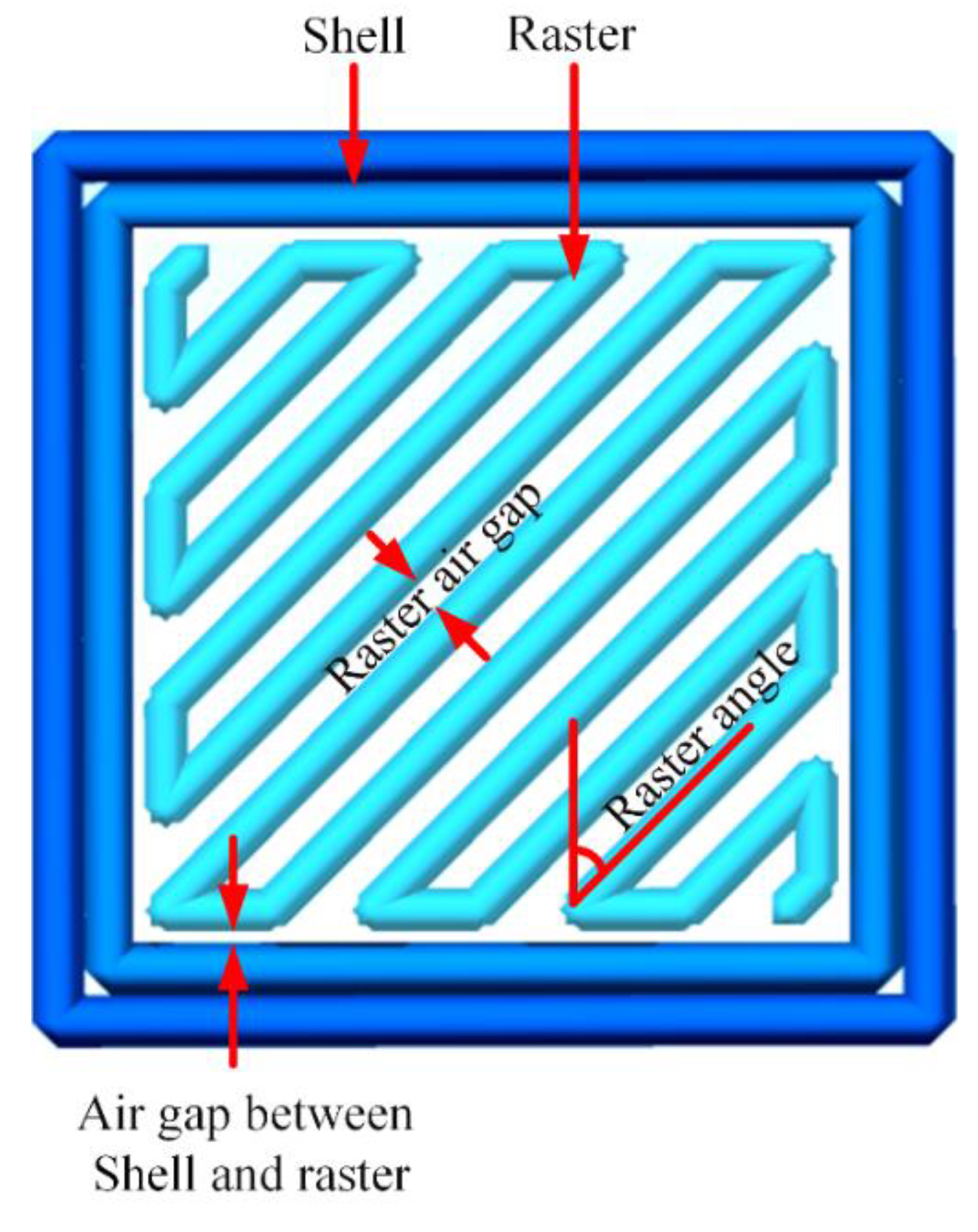
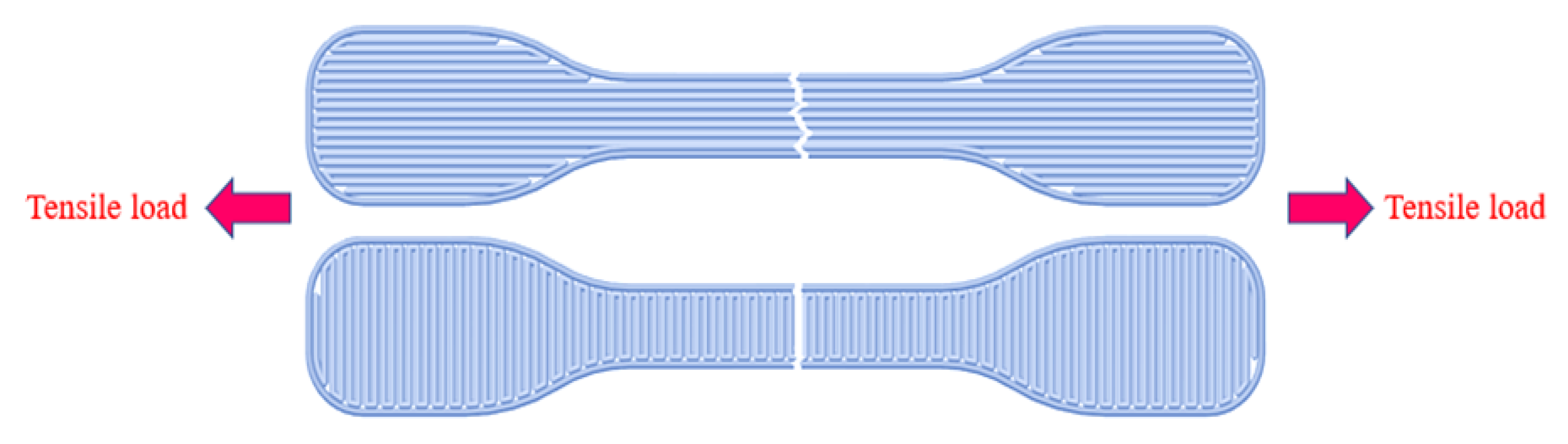
The current literature shows limited research on the impact of 3D printing parameters on the tensile properties of commercial PLA/Al filaments. This study focuses on PLA/Al as it has potential applications in aerospace, automotive, and biomedical engineering, where lightweight and robust materials are crucial. Commercial filaments were used for their reproducibility and availability. On the other hand, as mentioned, there are many parameters in the FFF process that can affect the strength and quality of printed parts. However, optimizing all parameters can be expensive and time-consuming, so the study focuses on two parameters which have a significant effect on the mechanical resistance of printed parts: printing speed and raster angle. Printing speed affects mechanical properties, quality, and production time, while the raster angle determines the orientation of the molecular structure, influencing mechanical properties such as tensile strength and elongation. This study uses the Taguchi method to investigate the impact of filament material parameters, printing speed, and raster angle on the tensile properties of commercial PLA/Al filaments and determine optimal parameter conditions. Results from both samples will be analyzed and compared.

2. Materials and Methods

2.1. Material and Parts Fabrication

To compare the mechanical properties, two commercial filaments from eSUN China were utilized in this study. The first filament was pure and known as Natural PLA filament, with a printing temperature range of 190–220 °C, while the second filament was a PLA/Al composite filament known as eAlfill Natural filament, with a printing temperature range of 200–220 °C. Both filaments had a diameter of 1.75 mm. The test specimens utilized in this study were created in SOLIDWORKS 2013 modeling software according to the DIN53504-S3A standard. The use of this standard offers advantages such as high geometric stability and reduced risk of injury [30]. The FFF 3D printing device used in this study was designed and developed by the authors based on an open-source model known as Delta Rostock. The key elements of the printer were the hotend section (E3D V5), extruder (MK8), heating bed (Delta PCB), cooling fans, control section (Arduino mega 2560, Ramps 1.4), and moving axes. The 3D printer manufactured and used in the study is shown in Figure 1.
Movement of the nozzle section is provided by moving three axes. Each axis is connected to a 1.8-degree stepper motor using a belt mechanism. The filament is pushed into the hotend section using an extruder. The hotend section makes the filament melt and melted material is pushed out through the nozzle by the force of the solid filament entrance. The extruded material from the nozzle lays down on the heat bed creating the first layer. The deposition of multiple layers above each other creates the final 3D product. The control section is responsible for regulating the movement of axes, the temperature of the hotend and heat bed, and also the extruder speed.
In order to ensure stability and prevent significant changes during the printing process, various 3D printer parameters needed to be defined and kept constant. Apart from the printing speed and raster angle, all other parameters were maintained at a constant level. Table 1 presents the 3D printer parameters that remained constant throughout the duration of the study.

2.2. Characterization Methods

The present research employed the SANTAM STM-150 tensile machine to analyze the tensile behavior. The tensile tests were performed at a speed of 2 mm/min. The tensile strength and elongation-at-break were chosen as the key output parameters for the tensile test. The printed test samples are shown in Figure 2.

2.3. Design of Experiments

To investigate the combined effects of various parameters on the tensile properties of printed parts, multiple samples need to be produced and tested with different levels of each parameter. DOE is employed to reduce the number of tests, save time and cost, and optimize manufacturing process parameters. The Taguchi method is commonly used to analyze experimental results and achieve the following objectives: identifying optimal conditions, evaluating the individual impact of each factor, and estimating performance under optimal conditions [31,32]. The Taguchi method utilizes either the signal-to-noise ratio (SNR) or analysis of variance (ANOVA) to achieve the desired results. ANOVA assesses the variance between different groups to observe the overall impact of each manufacturing process parameter on the ultimate properties. In contrast, SNR evaluates the response change to the nominal value in different noise conditions and determines the results by adjusting the process parameters based on the average output response. ANOVA is commonly used to assess the impact of each parameter percentage individually on the output, while SNR is employed to optimize multi-response processes by considering the contribution percentage and impact of more than one parameter on the output. Therefore, this study uses the SNR method to determine the optimal conditions of filament type, printing speed, and raster angle simultaneously [33,34].
In order to achieve optimal conditions, this approach employs a loss function to determine the deviation between the experimental value and the target value (derived from the average mechanical properties obtained from experimental results). The loss function is then converted into an SNR to assess the correlation between quality and variability. To obtain desirable qualitative characteristics, Taguchi categorizes them into the following three types [35,36,37].
(1) The closer to the nominal value, the better.
S N T = 10 log [ 1 n i = 1 n ( y i y n ) 2 ]
where S N T is employed when the objective is to minimize the variation around a specific value.
(2) The closer to the nominal value, the better.
S N S = 10 log [ 1 n i = 1 n y i 2 ]
where S N S is utilized to maximize the output response value.
(3) The bigger, the better.
S N L = 10 log [ 1 n i = 1 n 1 y i 2 ]
where S N L is utilized to maximize the output response value.
For the analysis of the data in this study, Minitab software was employed, utilizing the SNR response of the larger-the-better type to maximize the tensile properties of the 3D-printed parts. Table 2 presents the filament type with two different levels, printing speed, and raster angle with three different levels that were considered. The effect of using metal powder on the properties of printed samples is one of the main goals of this research. This is why two different filaments were used and selected as an input variable. According to the experience of the authors, printing speed is one of the most effective parameters for the adherence of rasters and layers together. This refers to the speed at which the extrusion nozzle moves across the surface of the heat bed. Therefore, it was selected as the second input parameter. The high level for printing speed was selected to be 30 mm/s. Increasing printing speed can accelerate the print time, but it can also compromise the quality of the final product due to possible issues such as inadequate layer adhesion, warping, or stringing. Moreover, the printing speed of 10 mm/s was chosen as the lowest level because speeds lower than this threshold do not appear to offer a cost-effective advantage. The raster angle in FFF refers to the angle between the path of the extruding nozzle and the X-axis of the printing heat bed. The raster angle can have an impact on the mechanical properties of the final product, particularly in terms of its strength in different directions. Typically, the raster angle can range from 0° to 90°. Therefore, the third input parameter was selected to be the raster angle. The selection of these raster angles was deliberate, with the aim of covering a broad range of angles and maintaining compatibility with different slicers used in 3D printing software. The main objective was to develop models capable of evaluating and contrasting the effectiveness of various printing parameters and settings on different surface types and angles [30]. Figure 3 shows a schematic of the raster angle. The experiments were designed based on Taguchi’s L18 orthogonal array. The experiments and their condition are listed in Table 3.

3. Results and Discussion

3.1. Tensile Strength

The tensile strength results after performing the 3D printing process are presented in Table 4.
Figure 4 displays the normal probability plot for tensile strength results using the Anderson–Darling method. As the p-value of 0.251 is higher than the significance level of 0.05, it indicates that the distribution of data is normal [37].
The outcomes of the SNR analysis are shown in Table 5, which ranks the parameters based on their effectiveness using the delta value obtained from the highest and lowest SNR values. The filament type was found to be the most impactful parameter in enhancing the tensile strength, followed by the raster angle and printing speed in second and third place, respectively. Furthermore, the SNR analysis facilitated the identification of the best level for each parameter. The highest SNR value indicates the optimal level, which in this case is the first level of filament type, the third level of raster angle, and the first level of printing speed. Consequently, the ideal conditions are PLA filament type, a raster angle of −30/60°, and a printing speed of 10 mm/s, as per the SNR analysis results.
Figure 5 illustrates the effect of parameters on the tensile strength, revealing that the PLA/Al composites exhibit lower tensile strength compared to pure PLA samples. There could be several reasons for this decrease in strength. One possible reason is the weak interfacial bonding between the Al particles and the polymer matrix (PLA), which can lead to the formation of voids and microcracks at the interface. This weak interfacial bonding can result in stress concentrations and lead to premature failure of the composite material. Another reason for the reduction in tensile strength can be the presence of agglomerates of particles. In materials science and engineering, agglomerates refer to the clusters or groups of particles that are bound together by weak intermolecular forces or physical interactions such as van der Waals forces, hydrogen bonding, or electrostatic interactions. Agglomerates can form when nanoparticles or microparticles are added to a polymer matrix, as the particles tend to agglomerate or clump together due to their high surface area and the attractive forces between them. These agglomerates can act as stress concentration sites and can cause defects in the composite structure, leading to a reduction in the mechanical properties. Agglomerates can also lead to non-uniform dispersion of the particles, causing inconsistencies in the material properties [38,39,40].
By analyzing the effect of raster angles based on Figure 5 and Figure 6a, it can be seen that 0/90° samples have the lowest tensile strength. As shown in schematic Figure 7, rasters perpendicular to the tensile load do not have much effect on bearing tensile force, and most of the whole force is borne by rasters parallel to the tensile load. In fact, in the samples where the rasters are located perpendicular to the tensile load, only the bonding between the rasters can withstand the applied tensile forces. On the other hand, when the rasters are oriented parallel to the tensile load, the applied load must break multiple rasters in each layer, as well as the polymer chain molecules, in order to cause sample failure. As a result, fracture in this case occurs along the rasters, requiring higher energy consumption [30,41]. The two other raster angles show a desirable tensile strength because all rasters are involved in enduring the tensile force.
Figure 6b demonstrates the stress-strain plot of samples with different printing speeds. As observable in Figure 5 and Figure 6b, the tensile strength does not show a significant change by changing printing speed. This is because the printing speed only affects the interlayer adhesion, and does not affect the longitudinal strength of the samples.

3.2. Elongation-at-Break

The results of the elongation-at-break are presented in Table 6.
Figure 8 demonstrates the normal probability plot for elongation-at-break results. As is obvious due to the p-value being greater than 0.05 (0.325), the distribution of data is normal.
The results of the SNR analysis are presented in Table 7, and indicate that the printing speed is the most influential parameter on the elongation-at-break. After printing speed, the raster angle and filament type are the next significant factors. The highest SNR value reflects the optimal level, which in this case is the third level of the printing speed, the second level of the raster angle, and the first level of the filament type. Therefore, according to the SNR analysis results, the optimal conditions are achieved by using a printing speed of 30 mm/s, raster angle of −45/45°, and PLA filament type.
Figure 9 illustrates the impact of various parameters on elongation-at-break. The findings reveal that the addition of Al particles to the polymer reduces the elongation of the samples, as it induces brittle behavior in the filament, resulting in a brittle final printed sample. However, the results of the printing speed parameter suggest that increasing it significantly increases elongation-at-break. As mentioned earlier, printing speed affects the interlayer bonding of samples. At lower printing speeds, the hot section moves slowly over the printed layer, resulting in gradual heat dissipation from the layer, which provides more time to form stronger bonds between layers. Conversely, higher printing speeds result in weaker interlayer bonds, mainly due to lower accuracy. The next layer’s raster is not accurately placed above the previous layer’s raster, which weakens the interlayer bonds. Elongation-at-break is mainly dependent on the material’s behavior after the yield point (plastic deformation). After the yield point is passed, the weak interlayer bonds cause more free slipping of layers. More free slipping of layers means more plastic deformation before rupture, leading to increased elongation-at-break. Furthermore, the results of the raster angle show that the −45/45° raster angle has the highest value of elongation-at-break, followed by the 30/60° and 0/90° raster angles. In the −45/45° raster angle, the tensile force is equally shared among all rasters, resulting in higher resistance of the rasters before breakpoint, thereby delaying the sample’s rupture. Conversely, in the other two raster angles, a significant fraction of the force is borne by only half of the rasters, causing them to break and resulting in lower elongation-at-break in these samples.

4. Conclusions

This study aimed to investigate the tensile behavior of 3D-printed composite samples using an FFF 3D printer. The study examined the impact of filament type, printing speed, and raster angle on the tensile strength and elongation-at-break of the samples. The research utilized two types of commercial filaments, namely pure PLA and PLA-Al composite, and implemented the printing process using a customized FFF printer. Tensile tests were conducted on the printed samples, and the Taguchi approach was used to analyze the impact of input parameters. The signal-to-noise ratio (SNR) was used to determine the effectiveness of each input parameter. The study findings revealed that the optimum values for obtaining maximum tensile strength of 61.85 MPa were found when using pure PLA filament, −30/60° of raster angle, and 10 mm/s of printing speed. Conversely, to obtain the maximum elongation-at-break of 17.7%, the optimal values were found when using pure PLA filament, −45/45° of raster angle, and 30 mm/s of printing speed. The results also demonstrated that the maximum tensile strength for PLA/Al composite samples is obtained at the printing speed of 20 mm/s and a raster angle of −45/45°, while the maximum elongation-at-break is obtained at the printing speed of 20 mm/s and a raster angle of −30/60°. The results of the SNR analysis demonstrated that the filament type had the most significant impact on tensile strength, while printing speed had the most significant impact on elongation-at-break.

Author Contributions

Conceptualization, R.H. and T.A.; Methodology, P.M. and S.A.; Software, R.H. and P.M.; Formal analysis, R.H., P.M. and T.A.; Investigation, R.H., P.M., T.A., S.A. and C.B.P.; Writing—original draft preparation, R.H. and P.M.; Writing—review and editing, T.A., S.A. and C.B.P. All authors have read and agreed to the published version of the manuscript.

Funding

This research received no external funding.

Data Availability Statement

The data presented in this study are available on request from the corresponding author.

Conflicts of Interest

The authors declare no conflict of interest.

References

  1. Hegab, H.; Khanna, N.; Monib, N.; Salem, A. Design for sustainable additive manufacturing: A review. Sustain. Mater. Technol. 2023, 35, 00576. [Google Scholar] [CrossRef]
  2. Feng, X.; Xia, L.; Jiang, Z.; Tian, M.; Zhang, S.; He, C. Dramatically promoted toluene destruction over Mn@ Na-Al2O3@ Al monolithic catalysts by Ce incorporation: Oxygen vacancy construction and reaction mechanism. Fuel 2022, 326, 125051. [Google Scholar] [CrossRef]
  3. Butt, J.; Mohaghegh, V. Combining Digital Twin and Machine Learning for the Fused Filament Fabrication Process. Metals 2022, 13, 24. [Google Scholar] [CrossRef]
  4. Rasouli, A.; Azdast, T.; Mohammadzadeh, H.; Mihankhah, P.; Hasanzadeh, R. Morphological properties and mechanical performance of polylactic acid scaffolds fabricated by a novel fused filament fabrication/gas foaming coupled method. Int. J. Adv. Manuf. Technol. 2022, 119, 7463–7474. [Google Scholar] [CrossRef]
  5. Guo, K.; Gou, G.; Lv, H.; Shan, M. Jointing of CFRP/5083 Aluminum Alloy by Induction Brazing: Processing, Connecting Mechanism, and Fatigue Performance. Coatings 2022, 12, 1559. [Google Scholar] [CrossRef]
  6. Kafle, A.; Luis, E.; Silwal, R.; Pan, H.M.; Shrestha, P.L.; Bastola, A.K. 3D/4D Printing of polymers: Fused deposition modelling (FDM), selective laser sintering (SLS), and stereolithography (SLA). Polymers 2021, 13, 3101. [Google Scholar] [CrossRef] [PubMed]
  7. Fu, Z.H.; Yang, B.J.; Shan, M.L.; Li, T.; Zhu, Z.Y.; Ma, C.P.; Zhang, X.; Gou, G.Q.; Wang, Z.R.; Gao, W. Hydrogen embrittlement behavior of SUS301L-MT stainless steel laser-arc hybrid welded joint localized zones. Corros. Sci. 2020, 164, 108337. [Google Scholar] [CrossRef]
  8. Azdast, T.; Hasanzadeh, R. Polylactide scaffold fabrication using a novel combination technique of fused deposition modeling and batch foaming: Dimensional accuracy and structural properties. Int. J. Adv. Manuf. Technol. 2021, 114, 1309–1321. [Google Scholar] [CrossRef]
  9. Hasanzadeh, R.; Azdast, T.; Mojaver, M.; Darvishi, M.M.; Park, C.B. Cost-effective and reproducible technologies for fabrication of tissue engineered scaffolds: The state-of-the-art and future perspectives. Polymer 2022, 244, 124681. [Google Scholar] [CrossRef]
  10. Diyana, Z.N.; Jumaidin, R.; Selamat, M.Z.; Ghazali, I.; Julmohammad, N.; Huda, N.; Ilyas, R.A. Physical properties of thermoplastic starch derived from natural resources and its blends: A review. Polymers 2021, 13, 1396. [Google Scholar] [CrossRef]
  11. Zhu, Z.Y.; Liu, Y.L.; Gou, G.Q.; Gao, W.; Chen, J. Effect of heat input on interfacial characterization of the butter joint of hot-rolling CP-Ti/Q235 bimetallic sheets by Laser+ CMT. Sci. Rep. 2021, 11, 10020. [Google Scholar] [CrossRef] [PubMed]
  12. Kılınç, A.Ç.; Goktas, A.A.; Keskin, Ö.Y.; Köktaş, S. Extrusion-Based 3D Printing of CuSn10 Bronze Parts: Production and Characterization. Metals 2021, 11, 1774. [Google Scholar] [CrossRef]
  13. Stansbury, J.W.; Idacavage, M.J. 3D printing with polymers: Challenges among expanding options and opportunities. Dent. Mater. 2016, 32, 54–64. [Google Scholar] [CrossRef]
  14. Awasthi, P.; Banerjee, S.S. Fused deposition modeling of thermoplastic elastomeric materials: Challenges and opportunities. Addit. Manuf. 2021, 46, 102177. [Google Scholar] [CrossRef]
  15. Zhang, S.; Han, B.; Zhang, T.; Chen, Y.; Xie, J.; Shen, Y.; Huang, L.; Qin, X.; Wu, Y.; Pu, K. High-temperature solid particle erosion characteristics and damage mechanism of AlxCoCrFeNiSi high-entropy alloy coatings prepared by laser cladding. Intermetallics 2023, 159, 107939. [Google Scholar] [CrossRef]
  16. Zhu, Q.; Chen, J.; Gou, G.; Chen, H.; Li, P. Ameliorated longitudinal critically refracted—Attenuation velocity method for welding residual stress measurement. J. Mater. Process. Technol. 2017, 246, 267–275. [Google Scholar] [CrossRef]
  17. Gonabadi, H.; Yadav, A.; Bull, S.J. The effect of processing parameters on the mechanical characteristics of PLA produced by a 3D FFF printer. Int. J. Adv. Manuf. Technol. 2020, 111, 695–709. [Google Scholar] [CrossRef]
  18. Wang, Z.; Dai, L.; Yao, J.; Guo, T.; Hrynsphan, D.; Tatsiana, S.; Chen, J. Enhanced adsorption and reduction performance of nitrate by Fe–Pd–Fe3O4 embedded multi-walled carbon nanotubes. Chemosphere 2021, 281, 130718. [Google Scholar] [CrossRef]
  19. Azdast, T.; Lee, R.E.; Hasanzadeh, R.; Moradian, M.; Shishavan, S.M. Investigation of mechanical and morphological properties of acrylonitrile butadiene styrene nanocomposite foams from analytical hierarchy process point of view. Polym. Bull. 2019, 76, 2579–2599. [Google Scholar] [CrossRef]
  20. Khalilarya, S.; Chitsaz, A.; Mojaver, P. Optimization of a combined heat and power system-based gasification of municipal solid waste of Urmia University student dormitories via ANOVA and Taguchi approaches. Int. J. Hydrog. Energy 2021, 46, 1815–1827. [Google Scholar] [CrossRef]
  21. Prihandana, G.S.; Sriani, T.; Jamaludin, M.F.; Yusof, F.; Arifvianto, B.; Mahardika, M. Parameters Optimization for Electropolishing Titanium by Using Taguchi-Based Pareto ANOVA. Metals 2023, 13, 392. [Google Scholar] [CrossRef]
  22. Fan, X.; Wei, G.; Lin, X.; Wang, X.; Si, Z.; Zhang, X.; Shao, Q.; Mangin, S.; Fullerton, E.; Jiang, L.; et al. Reversible switching of interlayer exchange coupling through atomically thin VO2 via electronic state modulation. Matter 2020, 2, 1582–1593. [Google Scholar] [CrossRef]
  23. Pavan, M.V.; Balamurugan, K.; Srinivasadesikan, V.; Lee, S.L. Impact and Shear Behavior of PLA/12% Cu Reinforced Composite Filament Printed at Different FDM Conditions. Arab. J. Sci. Eng. 2021, 46, 12709–12720. [Google Scholar] [CrossRef]
  24. Kottasamy, A.; Samykano, M.; Kadirgama, K.; Rahman, M.; Noor, M.M. Experimental investigation and prediction model for mechanical properties of copper-reinforced polylactic acid composites (Cu-PLA) using FDM-based 3D printing technique. Int. J. Adv. Manuf. Technol. 2022, 119, 5211–5232. [Google Scholar] [CrossRef]
  25. Hanon, M.M.; Alshammas, Y.; Zsidai, L. Effect of print orientation and bronze existence on tribological and mechanical properties of 3D-printed bronze/PLA composite. Int. J. Adv. Manuf. Technol. 2020, 108, 553–570. [Google Scholar] [CrossRef]
  26. Selvamani, S.K.; Rajan, K.; Samykano, M.; Kumar, R.R.; Kadirgama, K.; Mohan, R.V. Investigation of tensile properties of PLA–brass composite using FDM. Prog. Addit. Manuf. 2022, 7, 839–851. [Google Scholar] [CrossRef]
  27. Zhang, X.; Chen, L.; Mulholland, T.; Osswald, T.A. Effects of raster angle on the mechanical properties of PLA and Al/PLA composite part produced by fused deposition modeling. Polym. Adv. Technol. 2019, 30, 2122–2135. [Google Scholar] [CrossRef]
  28. Smirnov, A.; Seleznev, A.; Peretyagin, P.; Bentseva, E.; Pristinskiy, Y.; Kuznetsova, E.; Grigoriev, S. Rheological Characterization and Printability of Polylactide (PLA)-Alumina (Al2O3) Filaments for Fused Deposition Modeling (FDM). Materials 2022, 15, 8399. [Google Scholar] [CrossRef]
  29. Dou, H.; Cheng, Y.; Ye, W.; Zhang, D.; Li, J.; Miao, Z.; Rudykh, S. Effect of process parameters on tensile mechanical properties of 3D printing continuous carbon fiber-reinforced PLA composites. Materials 2020, 13, 3850. [Google Scholar] [CrossRef]
  30. Mihankhah, P.; Azdast, T.; Mohammadzadeh, H.; Hasanzadeh, R.; Aghaiee, S. Fused filament fabrication of biodegradable polylactic acid reinforced by nanoclay as a potential biomedical material. J. Thermoplast. Compos. Mater. 2023, 36, 961–983. [Google Scholar] [CrossRef]
  31. Chen, D.; Wang, Q.; Li, Y.; Li, Y.; Zhou, H.; Fan, Y. A general linear free energy relationship for predicting partition coefficients of neutral organic compounds. Chemosphere 2020, 247, 125869. [Google Scholar] [CrossRef] [PubMed]
  32. Heidari-Rarani, M.; Ezati, N.; Sadeghi, P.; Badrossamay, M.R. Optimization of FDM process parameters for tensile properties of polylactic acid specimens using Taguchi design of experiment method. J. Thermoplast. Compos. Mater. 2022, 35, 2435–2452. [Google Scholar] [CrossRef]
  33. Hasanzadeh, R.; Mojaver, P.; Chitsaz, A.; Mojaver, M.; Jalili, M.; Rosen, M.A. Biomass and low-density polyethylene waste composites gasification: Orthogonal array design of Taguchi technique for analysis and optimization. Int. J. Hydrog. Energy 2022, 47, 28819–28832. [Google Scholar] [CrossRef]
  34. Chen, Y.; Sun, S.; Zhang, T.; Zhou, X.; Li, S. Effects of post-weld heat treatment on the microstructure and mechanical properties of laser-welded NiTi/304SS joint with Ni filler. Mater. Sci. Eng., A 2020, 771, 138545. [Google Scholar] [CrossRef]
  35. Azdast, T.; Hasanzadeh, R.; Moradian, M. Improving impact strength in FSW of polymeric nanocomposites using stepwise tool design. Mater. Manuf. Process. 2018, 33, 343–349. [Google Scholar] [CrossRef]
  36. Wang, Z.; Chen, C.; Liu, H.; Hrynshpan, D.; Savitskaya, T.; Chen, J.; Chen, J. Enhanced denitrification performance of Alcaligenes sp. TB by Pd stimulating to produce membrane adaptation mechanism coupled with nanoscale zero-valent iron. Sci. Total Environ. 2020, 708, 135063. [Google Scholar] [CrossRef]
  37. Hasan Nejad, S.J.; Hasanzadeh, R.; Doniavi, A.; Modanloo, V. Finite element simulation analysis of laminated sheets in deep drawing process using response surface method. Int. J. Adv. Manuf. Technol. 2017, 93, 3245–3259. [Google Scholar] [CrossRef]
  38. Azwa, Z.N.; Yousif, B.F.; Manalo, A.C.; Karunasena, W. A review on the degradability of polymeric composites based on natural fibres. Mater. Des. 2013, 47, 424–442. [Google Scholar] [CrossRef]
  39. Shah, K.J.; Shukla, A.D.; Shah, D.O.; Imae, T. Effect of organic modifiers on dispersion of organoclay in polymer nanocomposites to improve mechanical properties. Polymer 2016, 97, 525–532. [Google Scholar] [CrossRef]
  40. Zare, Y. Study of nanoparticles aggregation/agglomeration in polymer particulate nanocomposites by mechanical properties. Compos. Part A Appl. Sci. Manuf. 2016, 84, 158–164. [Google Scholar] [CrossRef]
  41. Wu, W.; Geng, P.; Li, G.; Zhao, D.; Zhang, H.; Zhao, J. Influence of layer thickness and raster angle on the mechanical properties of 3D-printed PEEK and a comparative mechanical study between PEEK and ABS. Materials 2015, 8, 5834–5846. [Google Scholar] [CrossRef] [PubMed]
Figure 1. FFF Delta 3D printer.
Metals 13 01013 g001
Figure 2. Printed test samples.
Metals 13 01013 g002
Figure 3. Schematic of raster angle.
Metals 13 01013 g003
Figure 4. Normal probability plot of tensile strength.
Metals 13 01013 g004
Figure 5. SNR diagrams of tensile strength.
Metals 13 01013 g005
Figure 6. Stress-strain plot of (a) different raster angles; (b) different printing speeds.
Metals 13 01013 g006
Figure 7. Schematic of fracture of rasters.
Metals 13 01013 g007
Figure 8. Normal probability plot of elongation-at-break.
Metals 13 01013 g008
Figure 9. SNR diagrams of elongation at break.
Metals 13 01013 g009
Table 1. Constant printing parameters during experiments.
ParametersConstant ValuesUnits
Nozzle temperature220(°C)
Bed temperature60(°C)
Nozzle diameter0.4(mm)
Layer height0.3(mm)
Infill patternLinier line-
Infill percentage100%
Shell1Wall
Table 2. Input parameters and their levels.
ParameterLevel
123
Filament typePure PLAPLA/Al-
Printing speed (mm/s)102030
Raster angle (°)0/90−45/45−30/60
Table 3. Design of experiments according to L18 orthogonal array of Taguchi.
Experiment NumberFilament TypePrinting Speed (mm/s)Raster Angle (°)
1Pure PLA100/90
2Pure PLA10−45/45
3Pure PLA10−30/60
4Pure PLA200/90
5Pure PLA20−45/45
6Pure PLA20−30/60
7Pure PLA300/90
8Pure PLA30−45/45
9Pure PLA30−30/60
10PLA/Al100/90
11PLA/Al10−45/45
12PLA/Al10−30/60
13PLA/Al200/90
14PLA/Al20−45/45
15PLA/Al20−30/60
16PLA/Al300/90
17PLA/Al30−45/45
18PLA/Al30−30/60
Table 4. Tensile strength results.
RunTensile Strength (MPa)RunTensile Strength (MPa)
154.02 ± 2.21040.62 ± 1.4
260.39 ± 2.11146.75 ± 1.5
361.85 ± 3.21242.76 ± 0.9
451.19 ± 1.91343.38 ± 1.6
554.08 ± 0.81447.82 ± 2.3
652.64 ± 1.31544.83 ± 3.0
750.34 ± 1.21643.92 ± 2.7
852.88 ± 2.11745.52 ± 2.2
963.23 ± 1.71846.13 ± 2.0
Table 5. SNR results of tensile strength.
LevelFilament TypePrinting SpeedRaster Angle
155.6351.0747.25
244.6348.9951.24
3------50.3451.91
Delta10.992.084.66
Rank132
Table 6. Elongation-at-break results.
RunElongation-at-Break (%)RunElongation-at-Break (%)
18.69 ± 0.06109.36 ± 0.02
212.33 ± 0.041110.04 ± 0.03
311.60 ± 0.03128.21 ± 0.02
48.94 ± 0.07139.18 ± 0.01
517.13 ± 0.071412.46 ± 0.04
612.70 ± 0.02158.20 ± 0.03
711.25 ± 0.031614.58 ± 0.07
817.70 ± 0.041715.54 ± 0.05
911.56 ± 0.041813.60 ± 0.04
Table 7. SNR results of elongation at break.
LevelFilament TypePrinting SpeedRaster Angle
112.4310.0310.33
211.2411.4414.2
3------14.0410.98
Delta1.194.013.87
Rank312
Disclaimer/Publisher’s Note: The statements, opinions and data contained in all publications are solely those of the individual author(s) and contributor(s) and not of MDPI and/or the editor(s). MDPI and/or the editor(s) disclaim responsibility for any injury to people or property resulting from any ideas, methods, instructions or products referred to in the content.

