1. Introduction
Electric arc furnaces (EAF) produced more than 500 million t of crude steel in 2021 [
1]. Although scrap is the primary iron carrier, the EAF is also a suitable aggregate for processing direct reduced iron (DRI) or hot briquetted iron (HBI). This combination of direct reduction reactor (DR) and EAF can be considered the major ore-based steelmaking strategy in natural gas (NG)-rich countries such as Mexico [
2], Saudi Arabia [
3,
4], and United Arabic Emirates [
5]. Nowadays, the 119 Mt DRI production in 2021 [
6] is just a minor share of the total ferrous feed for global steel production. However, due to the ambitious climate targets of the European Union [
7], this technology may gain greater importance in the future [
8]. Therefore, the processing behavior of sponge iron is also of significant interest.
Many authors investigated the DRI melting behavior in the past. From the perspective of a single pellet, one must distinguish between the dissolution in liquid steel, hot metal, and slags. González et al. [
9] mathematically describe the initial formation of a solid superficial layer on the pellet in contact with liquid iron. The layer increases the particle diameter from 12 to 18 mm, which starts to soften after approximately 6 s. Depending on the considered EAF arc length, the calculated diameter reaches 0 mm after 13 to 17 s. The melting rate critically depends on the initial pellet diameter. Pineda-Martínez et al. [
10] report similar results in contact with non-reactive slags. However, due to the lower heat transfer, the melting times are dramatically higher compared to the liquid steel case. Besides the particle size, bath stirring is a decisive factor, as forced convection critically increases heat transport. Ramirez-Argaez et al. [
11] further use CFD modeling to study the multiphase slag–steel–DRI system, with similar results. Pfeiffer et al. [
12] confirm this trend experimentally. They submerge single samples of DRI and HBI into a liquid pool and quench the specimen after predefined times. Carbon-free DRI initially acquires solid layers from steel as well as slags. However, the higher the DRI carbon content, the faster the pellet liquefies in steel. Nevertheless, even highly carburized sponge iron remains solid in slag after three seconds of dipping. The authors explain this difference analytically using the Prandtl number, which is increased by a factor of approximately 1000 in the slag case. Samples dipped into saturated hot metal melt much faster, even if the melt temperature is below the iron liquidus temperature. Carbon diffusion from the liquid to the solid phase explains that. Penz et al. [
13,
14,
15] investigate this phenomenon for scrap melting in basic oxygen furnace (BOF) conditions. After forming the initial solid shell, carbon diffuses as long as the liquidus temperature falls below the melting point. Once that happens, melting progresses.
DRI is usually continuously charged through the fifth hole in the EAF cover. To gain consistent flat bath operation, DRI-based EAF are practiced with up to 30% hot heel [
16,
17]. This operation is characterized by a short and stable arc mode and a smoothly increasing bath level. The ideal charging point is located in the hot spot, in the center of the three AC-EAF electrodes. Depending on the DRI temperature and the melting capacity, charging rates are limited to avoid the formation of so-called “icebergs” or “ferrobergs”. Typical values range from 34 kg/(min∙MW) [
16,
18,
19] for cold DRI up to 55 kg/(min∙MW) [
20] for hot DRI. Consequently, hot DRI feeding is beneficial not only in terms of energy consumption, but also in terms of the charging rate. Therefore, lower tap-to-tap times can be expected.
In recent years, a lot of research has been conducted with a focus on electric steelmaking. The most important topics in this case are slag operation [
17,
21,
22,
23,
24], process modelling [
25,
26], and application of alternative carbon sources [
27,
28,
29]. These topics are of decisive importance when it comes to optimizing the EAF process for CO
2-neutral steelmaking in the future. Slag operation defines the process sequence in multiple aspects. On the one hand, slag foaming covers the electric arc and avoids radiation losses. Furthermore, it defines the yield of metallic iron since it is high in (FeO), the partition of harmful elements such as phosphorus, and the refractory lifetime. The use of biomass-based carbon carriers provides the chance to almost fully reduce fossil-based carbon emissions, as the electric arc furnace relies on a minimum amount of carbon for slag foaming operation. Lastly, process simulation and modelling enhance process efficiency. The better one’s ability to simulate the EAF and its mass and energy balances, the more energy and input materials, such as slag forming oxides, can be saved.
However, there is still little data available in two respects. First is the application of DRI based on hydrogen. This kind of sponge iron is free of carbon. Therefore, its liquidus temperature is significantly higher than that of the conventional one. This difference may lead to a different behavior during the melting step in the EAF. Second is the direct observation of the feed material in the electric arc; it would be of great interest to learn more about its behavior. This study aims to generate deeper understanding in both mentioned respects and analyzes the behavior of DRI in an electric arc. Next to hydrogen-based carbon-free material, carburized samples and a continuous slag feed are tested. The observations provide more profound knowledge about the melting procedure and can be used to explain the optimal DRI charging strategy and deliver an idea about the final crude steel quality.
2. Materials and Methods
Table 1 lists the applied iron ores and their composition. An industry partner provided the samples and the chemical compositions. DR-grade pellets were used in tests 0, 1, and 2; a similar fine ore to test DRI fines from fluidized bed reduction was used in Test 3. To make the result of the slag Test 4 clearer, a BF-grade pellet with a higher gangue content was tested.
The pellet samples were reduced in a vertical reduction furnace (VRF) using a 75 mm diameter retort, precisely described in [
30,
31]. This is a standard aggregate used, for example, to perform standard tests such as ISO11258 [
32]. The retort is fixed on a scale, providing the possibility to monitor the weight loss during the test. The reduction gas is preheated in the furnace chamber; it enters the retort from the bottom and exits through the top into the off-gas duct. The thermocouple measures the temperature in the center of the pellet load. Approximately 500 g pellets were charged. After heating up to 900 °C under nitrogen purging, 25 NL/min pure H
2 was applied. Once the mass loss reached the demanded metallization degree (MD), the test was stopped, and the material was cooled under a nitrogen atmosphere. Three pellet samples were prepared: two from the DR-pellets were reduced to 90% and 94% MD; one from the BF-pellets was reduced to 90% MD. In the same retort, the highly reduced DR-grade DRI was carburized afterward under 8 NL/min CH
4 at 800 °C. According to the mass balance, it contains 2.1% carbon; due to the high initial reduction, this is considered a reasonable presumption.
The fine ore was preoxidized in a heat treatment furnace [
33] for 8 h at 700 °C. The prereduction step is essential as hematitic ore is beneficial in terms of reducibility and fluidization behavior. The sample was reduced in a 68 mm fluidized bed reactor. This reactor uses the same furnace as the 75 mm retort; its properties and dimensions are described in detail by Spreitzer and Schenk in [
34]. Reduction was performed using 6 NL/min N
2 and 15 NL/min H
2 without application of additional pressure in the reduction chamber. A grid with holes of 0.4 mm in diameter was used, which is optimal for such fine-grained iron ores. The final MD is approximately 89.4%, which is determined by mass balance calculation.
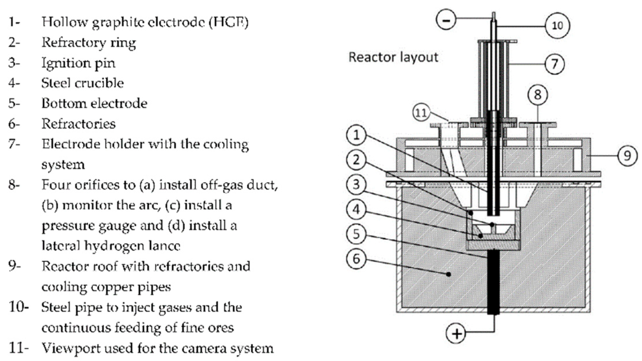
The melting tests were performed in the hydrogen plasma smelting reduction (HPSR) reactor at the chair of ferrous metallurgy, Montanuniversität Leoben, Austria, whose layout is visualized in
Figure 1. This aggregate, extensively described in [
35,
36], is usually applied for direct smelting reduction tests. The method itself is well established. Regarding reduction in atmosphere with hydrogen, numerous research topics were investigated in the past. Optimizations were conducted in case of arc stability [
37], electrode shapes [
38] and ore prereduction degree [
39]. If operated in an inert atmosphere as in this test series, it can be considered a DC laboratory-scale electric arc furnace with a graphite electrode. The electrode had a diameter of 26 mm, a 10 mm tip, and a 5 mm axial opening through which the nitrogen was supplied.
The samples were charged batchwise in a steel crucible whose exact dimensions are summarized by Ernst et al. [
39]; all experiments were performed with 2 NL/min nitrogen purging.
Table 2 summarizes the performed tests. Test 0 acts as a method test and is not further evaluated. In Test 4, 14.0 g CaO and 3.1 g MgO were continuously fed through a hollow electrode. Technically pure oxides with 95 and 99% purity from Carl Roth GmbH + Co. KG, Karlsruhe, Germany were used. Initially, the transformer current was set to 100 A. During the test, it was decreased stepwise, depending on the transformer temperature and voltage. For that, a silicon-controlled rectifier (SCR) was applied. In the final approx. 2.5 min of Test 4, the power input was maximized to intensify the slag–metal stirring.
The experiments were evaluated in multiple ways. The HPSR reactor had an AXIS-Q1775 camera system (Axis Communications AB, Lund, Sweden) and a GAM 200 mass spectrometer (Pfeiffer Vacuum Technologies AG, Aßlar, Germany), which provide the possibility to monitor the electric arc as well as the off-gas. Further, voltage and current values were recorded and documented.
The crucibles were visually checked using a Sony Alpha 6000 DSLM camera (Sony Group Corporation, Tokyo, Japan) equipped with a Sigma Contemporary 30 mm lens (Sigma Corporation, Kawasaki, Japan). Afterward, the crucibles were embedded, cut, and the cross-sections were metallographically prepared.
Figure 2 details the cutting scheme. Etching was performed using a 1% nital solution to highlight the transition between the crucible and the sample. We adjusted the time iteratively between 6 and 10 s.
The microsections were investigated using a Keyence VHX 7000 digital microscope (Keyence Corporation, Osaka, Japan). The chemical analysis of the gangue layer was performed via SEM-EDX Fei Quanta 200Mk2 (FEI Company, Hillsboro, OR, USA). Small samples were taken from two crucibles, Test 2 with carbonaceous DRI and Test 3 with DRI fines, to analyze carbon content using LECO. Test 3 can be considered representative for the carbon-free DRI tests.
3. Results
Figure 3 shows the voltage as a function of the current for all tests. The different point clouds represent stability regions from different controlling ranges. The more concentrated the points in the diagram are, the more stable the arc is. Since only minor fluctuations could be observed, arc operation was relatively stable in all cases. Nevertheless, the violet Test 3 with the DRI fines shows the broadest range, while the green Test 4 dots are relatively closely distributed. That confirms the arc-stabilizing effect of a slag layer on top of the melt.
All relevant furnace parts, the crucible, and the sample materials were weighed for a mass balance. All balances are negative, with Test 2, C-DRI, having the largest mass loss through the gas phase. During this test, 27.0 g dusted and evaporated from the furnace chamber without becoming separated in the off-gas filter. Further, the reduction reactions influence the mass balance in this case. That was the least pronounced at Test 4 with the slag cover and only 2.8 g loss. Tests 1 and 3 are in the middle, with—11.3 and—14.9 g, respectively.
Figure 4 shows in situ photographs during the carbon and slag-free Tests 1 and 3. The electric arc moves over the surface and melts the sponge iron. The pellets in
Figure 4a offer a contrast to describe the progress better. A liquid pool is on the left-hand side, while a pellet structure can still be observed on the right side. In contrast, the DRI-fines in
Figure 4b do not show any contours, making a detailed observation difficult.
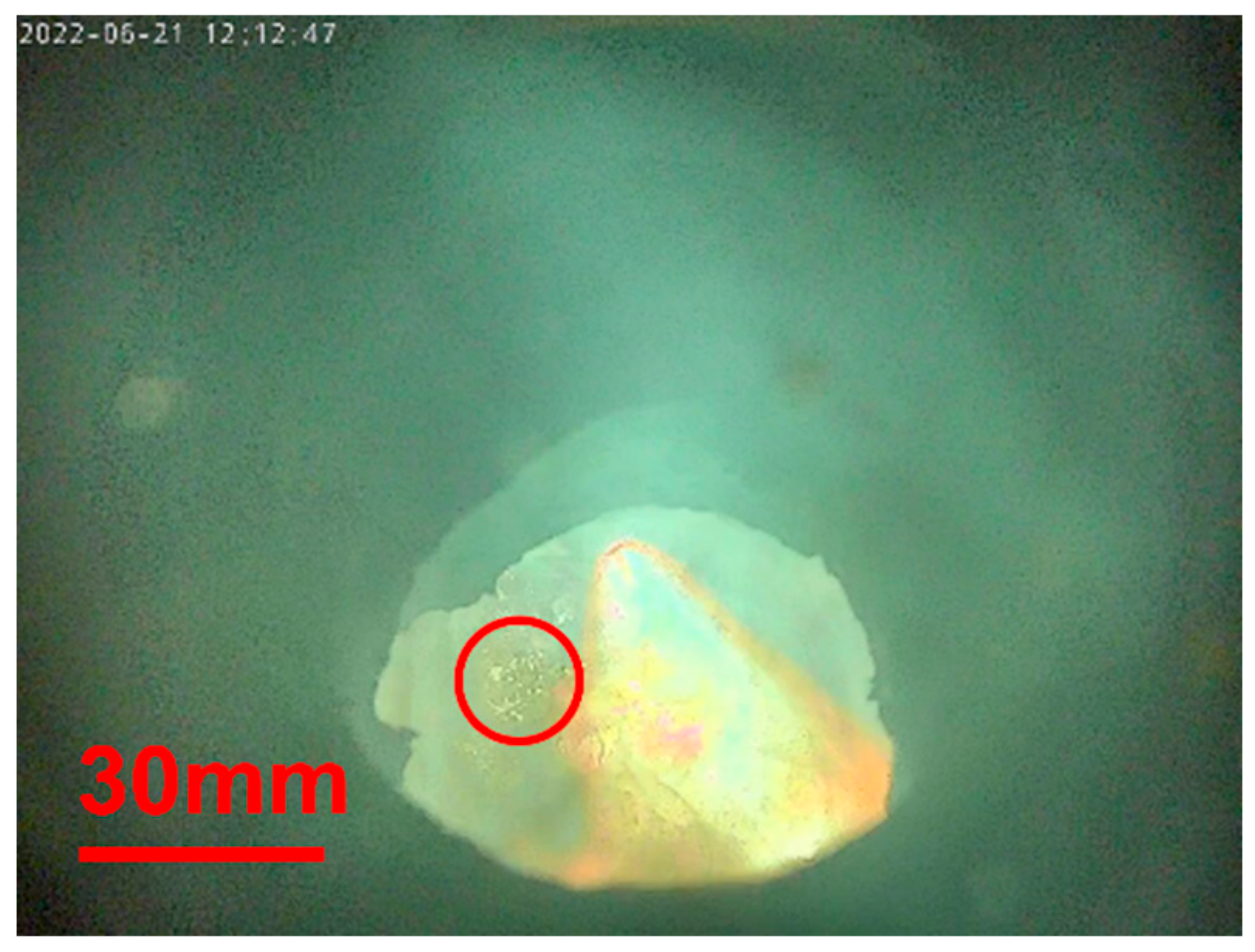
The formation of bubbles characterizes the carburized sample in
Figure 5; see the red circle. These blisters indicate a reduction in residual iron oxide with carbon in the sponge iron sample.
The dissolution of slag-forming oxide can be observed in
Figure 6. The photograph in (a) was taken directly after the addition of powder. In (b), the powder dissolves in the superficial slag layer; see the red circled spot. After charging the oxide powder in (c), the whole surface seems to glow. That differs from the other samples in which the intensive cooling effect through the steel crucible leads to a localized hot spot. This appearance demonstrates the insulating effect of the slag layer.
Figure 7 shows the off-gas analysis of Test 2 with carburized DRI. The high CO and CO
2 amounts indicate a reduction in residual iron oxide, confirming the observation above. The carbon content of 0.75%, which significantly decreased from the DRI, correlates with the result. A further striking aspect is the increasing hydrogen amount resulting from moisture in the furnace refractory. The higher the temperature, the more moisture is released, which reacts to H
2 and CO after the heterogeneous shift reaction.
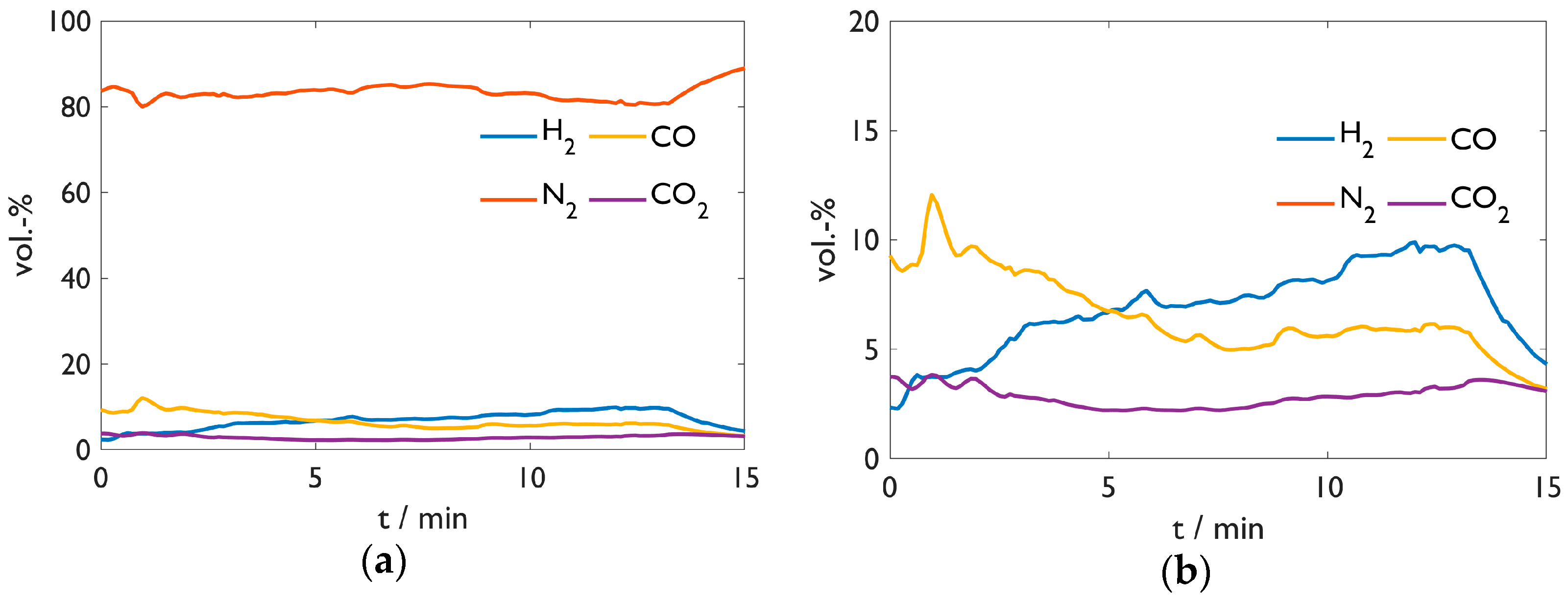
Figure 8 provides the off-gas analysis of Test 3 with the DRI fines. H
2 shows an analogous behavior as above; CO and CO
2 result from electrode burn-off as the sample contains no carbon. Unfortunately, the analysis of Test 1 was lost due to a software issue. Nevertheless,
Figure 8 is representative of exhaust gas compositions of the carbon-free samples in Tests 1, 3, and 4. Sample 3 remained almost carbon-free with 0.09%, which may have resulted from interactions with the steel crucible or the graphite electrode.
Figure 9 shows the sample crucibles after the tests. Red dust settles superficially. The most plausible explanation is the formation of iron oxides or hydroxides from the vaporized Fe with moisture from the furnace refractory. That aligns with the slag-covered sample in (d). On the one hand, it shows a primarily grey color; on the other hand, this sample evaporated the least. While the samples in (a) and (b) present a rough surface, the slag layer in (d) is relatively smooth but brittle with many cracks. This layer’s dark grey color indicates a high amount of iron oxide. Tests 1 and 3 imply a formation of a concentric structure from the temperature gradient around the electric arc.
Looking at the carburized DRI sample from Test 2 in (b), two aspects catch the eye. Firstly, lots of droplets cover the crucible on the lower right-hand side. Secondly, the sample surface appears less metallic but somewhat yellowish and glassy. A possible explanation for this appearance may be that CO blisters from reduction reactions splash out metallic droplets. These droplets arrive on the crucible surface. Further, the blisters drag the gangue onto the surface of the sample. The splashes also explain the pronounced mass loss, as some could land in the furnace refractory without being noticed.
Figure 10 shows the top layer particle from Test 2 as a digital microscope image from the upper and lower side. While (a) looks metallic with many blisters, (b) seems glassy.
Table 3 provides the approximate composition of the mentioned particle from both sides, determined by SEM-EDX. Although the iron oxide content in the lower part is slightly higher, the compositions do not differ significantly. The shiny gray color indicates that it is partly metalized. Nevertheless, SEM-EDX does not provide the possibility to differentiate between Fe
met, Fe
2+, and Fe
3+.
Figure 11 shows the digital microscope images of the cross-sections. The following aspects are noticeable:
The carbon-free samples from Tests 1, 3, and 4 show numerous pores, especially for the fine-DRI sample in (c), with one big blister. Further, they contain dark spots indicative of gangue inclusions.
The carbon-bearing sample in (b) looks completely different in this case. It forms a dense structure without pores and inclusions. This behavior correlates with the macroscopic observations and the gangue being agglomerated and collected on the sample top.
Samples in (a), (b) and (c) are merged with the crucible. The opposite is the case in (d). The slag frames the steel; the straight borderline indicates the absence of liquefying of the crucible. This picture is even more striking since the crucible center appears enriched with slag; compare the cutting scheme in
Figure 2.
Author Contributions
Conceptualization: A.P. and J.S.; methodology: A.P. and D.E.; validation: J.S. and G.W.; formal analysis: J.S.; resources: H.Z., J.S. and G.W.; writing—original draft preparation: A.P.; writing—review and editing: J.S., D.E., H.Z. and G.W.; visualization: A.P.; supervision: J.S. and G.W.; project administration: G.W.; funding acquisition: J.S. All authors have read and agreed to the published version of the manuscript.
Funding
This research was funded by K1-MET GmbH, metallurgical competence center (funding number FFG No. 869295). The research program of the K1-MET competence center is supported by COMET (Competence Center for Excellent Technologies), the Austrian program for competence centers. COMET is funded by the Federal Ministry for Climate Action, Environment, Energy, Mobility, Innovation, and Technology, the Federal Ministry for Labour and Economy, the provinces of Upper Austria, Tyrol, and Styria, and the Styrian Business Promotion Agency (SFG). In addition, this research work was partially financed by the industrial partners Primetals Technologies Austria GmbH, voestalpine Stahl GmbH, voestalpine Stahl Donawitz GmbH and thyssenkrupp Steel Europe AG, and the scientific partner Montanuniversität Leoben.
Data Availability Statement
The data presented in this study are available within the article.
Conflicts of Interest
The authors declare no conflict of interest.
References
- World Steel in Figures. Available online: https://worldsteel.org/steel-topics/statistics/world-steel-in-figures/ (accessed on 23 September 2022).
- Lule, R.; Lopez, F.; Espinoza, J.; Torres, R.; Morales, G. The Experience of ArcelorMittal Lázaro Cardenas Flat Carbon. Direct Midrex 2009, 3, 3–8. [Google Scholar]
- Bayer, F.; Strasser, J.; Trenkler, H. Hadeed’s new flat-steel mill at Al-Jubail-from Mini to Midi. Steel Times 2000, 228, 364. [Google Scholar]
- Jung, H.; Al-lbrahim, N.; Al-Sayegh, A.; Kaspar, S.; Pirklbauer, W. Hadeed-concept and latest results of the world’s largest EAF plant for long products on DRI-basis. Rev. Métallurgie 1994, 91, 1123–1130. [Google Scholar] [CrossRef]
- DRI Technology at Emirates Steel|Tenova. Available online: https://tenova.com/newsroom/latest-tenova/dri-technology-emirates-steel (accessed on 24 January 2023).
- Midrex Technologies, Inc. World DRI Production Reaches 119.2 Mt in 2021 Midrex Publishes World Direct Reduction Statistics. Available online: https://www.midrex.com/company-news/world-dri-production-reaches-119-2-mt-in-2021-midrex-publishes-world-direct-reduction-statistics/ (accessed on 28 September 2022).
- Eder, W. Environment–Climate–Energy: Quo Vadis, Industry? Berg Huettenmaenn. Mon. 2017, 162, 494–497. [Google Scholar] [CrossRef]
- Griesser, A.; Buergler, T. Use of HBI in Blast Furnace. Berg Huettenmaenn. Mon. 2019, 164, 267–273. [Google Scholar] [CrossRef]
- González, O.J.P.; Ramírez-Argáez, M.A.; Conejo, A.N. Mathematical Modeling of the Melting Rate of Metallic Particles in the Electric Arc Furnace. ISIJ Int. 2010, 50, 9–16. [Google Scholar] [CrossRef]
- Pineda-Martínez, E.; Hernández-Bocanegra, C.A.; Conejo, A.N.; Ramirez-Argaez, M.A. Mathematical Modeling of the Melting of Sponge Iron in a Bath of Non-Reactive Molten Slag. ISIJ Int. 2015, 55, 1906–1915. [Google Scholar] [CrossRef]
- Ramirez-Argaez, M.A.; Conejo, A.N.; López-Cornejo, M.S. Mathematical Modeling of the Melting Rate of Metallic Particles in the EAF under Multiphase Flow. ISIJ Int. 2015, 55, 117–125. [Google Scholar] [CrossRef]
- Pfeiffer, A.; Wimmer, G.; Schenk, J. Investigations on the Interaction Behavior between Direct Reduced Iron and Various Melts. Materials 2022, 15, 5691. [Google Scholar] [CrossRef]
- Penz, F.; Schenk, J.; Ammer, R.; Klösch, G.; Pastucha, K. Dissolution of Scrap in Hot Metal under Linz–Donawitz (LD) Steelmaking Conditions. Metals 2018, 8, 1078. [Google Scholar] [CrossRef]
- Penz, F.M.; Schenk, J. A Review of Steel Scrap Melting in Molten Iron-Carbon Melts. Steel Res. Int. 2019, 90, 1900124. [Google Scholar] [CrossRef]
- Penz, F.M.; Schenk, J.; Ammer, R.; Klösch, G.; Pastucha, K.; Reischl, M. Diffusive Steel Scrap Melting in Carbon-Saturated Hot Metal-Phenomenological Investigation at the Solid⁻Liquid Interface. Materials 2019, 12, 1385. [Google Scholar] [CrossRef] [PubMed]
- Hornby, S.; Madias, J.; Torre, F. Myths and realities of charging DRI/HBI in electric arc furnaces. Iron Steel Technol. 2016, 81–90. [Google Scholar] [CrossRef]
- Kirschen, M.; Hay, T.; Echterhof, T. Process Improvements for Direct Reduced Iron Melting in the Electric Arc Furnace with Emphasis on Slag Operation. Processes 2021, 9, 402. [Google Scholar] [CrossRef]
- Hornby, S.; Madias, J.; Torre, F. DRI/HBI-exploding the myths. Steel Times Int. 2016, 40, 24. [Google Scholar]
- Omar, A.M.; Appasamy, T.A.; Memoli, F. DC EAF with high DRI feeding rates through multipoint injection. Metall. Plant Technol. Int. 2004, 27, 58–67. [Google Scholar]
- Al Dhaeri, A.; Razza, P.; Patrizio, D. Excelent operating results of the integrated minimill #1 at Emirates Steel Industries: Danieli. MPT Int. 2010, 33, 34–40. [Google Scholar]
- Heo, J.; Park, J.H. Interfacial reactions between magnesia refractory and electric arc furnace (EAF) slag with use of direct reduced iron (DRI) as raw material. Ceram. Int. 2022, 48, 4526–4538. [Google Scholar] [CrossRef]
- Oh, M.K.; Kim, T.S.; Park, J.H. Effect of CaF2 on Phosphorus Refining from Molten Steel by Electric Arc Furnace Slag using Direct Reduced Iron (DRI) as a Raw Material. Met. Mater. Trans B 2020, 51, 3028–3038. [Google Scholar] [CrossRef]
- Heo, J.H.; Park, J.H. Effect of Direct Reduced Iron (DRI) on Dephosphorization of Molten Steel by Electric Arc Furnace Slag. Met. Mater. Trans. B 2018, 49, 3381–3389. [Google Scholar] [CrossRef]
- Heo, J.H.; Park, J.H. Assessment of Physicochemical Properties of Electrical Arc Furnace Slag and Their Effects on Foamability. Met. Mater. Trans. B 2019, 50, 2959–2968. [Google Scholar] [CrossRef]
- Hay, T.; Visuri, V.-V.; Aula, M.; Echterhof, T. A Review of Mathematical Process Models for the Electric Arc Furnace Process. Steel Res. Int. 2021, 92, 2000395. [Google Scholar] [CrossRef]
- Hay, T.; Echterhof, T.; Visuri, V.-V. Development of an Electric Arc Furnace Simulator Based on a Comprehensive Dynamic Process Model. Processes 2019, 7, 852. [Google Scholar] [CrossRef]
- Kieush, L.; Schenk, J.; Koveria, A.; Rantitsch, G.; Hrubiak, A.; Hopfinger, H. Utilization of Renewable Carbon in Electric Arc Furnace-Based Steel Production: Comparative Evaluation of Properties of Conventional and Non-Conventional Carbon-Bearing Sources. Metals 2023, 13, 722. [Google Scholar] [CrossRef]
- Echterhof, T. Review on the Use of Alternative Carbon Sources in EAF Steelmaking. Metals 2021, 11, 222. [Google Scholar] [CrossRef]
- Kieush, L.; Rieger, J.; Schenk, J.; Brondi, C.; Rovelli, D.; Echterhof, T.; Cirilli, F.; Thaler, C.; Jaeger, N.; Snaet, D.; et al. A Comprehensive Review of Secondary Carbon Bio-Carriers for Application in Metallurgical Processes: Utilization of Torrefied Biomass in Steel Production. Metals 2022, 12, 2005. [Google Scholar] [CrossRef]
- Hanel, M. Characterization of Ferrous Burden Material for Use in Ironmaking Technologies. Ph.D. Thesis, Montanuniversität Leoben, Leoben, Austria, 2014. [Google Scholar]
- Bhattacharyya, A.; Schenk, J.; Jäger, M.; Stocker, H.; Thaler, C. Experimental Simulation of the Interaction of Slag and Hot Metal with Coke at the Bosh Region of Blast Furnace. Berg Huettenmaenn. Mon. 2017, 162, 28–33. [Google Scholar] [CrossRef]
- ISO 11258:2015. ISO. Available online: https://www.iso.org/standard/62145.html (accessed on 13 May 2023).
- Spreitzer, D. Development of Characterization Methods for the Evaluation of the Kinetic Behavior and the Fluidization of Iron Ore Fines during Hydrogen-Induced Fluidized Bed Reduction. Ph.D. Thesis, University of Leoben, Leoben, Austria, 2021. [Google Scholar]
- Spreitzer, D.; Schenk, J. Iron Ore Reduction by Hydrogen Using a Laboratory Scale Fluidized Bed Reactor: Kinetic Investigation—Experimental Setup and Method for Determination. Met. Mater. Trans. B 2019, 50, 2471–2484. [Google Scholar] [CrossRef]
- Ernst, D.; Zarl, M.A.; Cejka, J.; Schenk, J. A New Methodological Approach on the Characterization of Optimal Charging Rates at the Hydrogen Plasma Smelting Reduction Process Part 2: Results. Materials 2022, 15, 4065. [Google Scholar] [CrossRef]
- Zarl, M.A.; Ernst, D.; Cejka, J.; Schenk, J. A New Methodological Approach to the Characterization of Optimal Charging Rates at the Hydrogen Plasma Smelting Reduction Process Part 1: Method. Materials 2022, 15, 4767. [Google Scholar] [CrossRef]
- Zarl, M.A.; Farkas, M.A.; Schenk, J. A Study on the Stability Fields of Arc Plasma in the HPSR Process. Metals 2020, 10, 1394. [Google Scholar] [CrossRef]
- Ernst, D.; Zarl, M.A.; Farkas, M.A.; Schenk, J. Effects of the Electrodes’ Shape and Graphite Quality on the Arc Stability During Hydrogen Plasma Smelting Reduction of Iron Ores. Steel Res. Int. 2023, 2200818. [Google Scholar] [CrossRef]
- Ernst, D.; Manzoor, U.; Souza Filho, I.R.; Zarl, M.A.; Schenk, J. Impact of Iron Ore Pre-Reduction Degree on the Hydrogen Plasma Smelting Reduction Process. Metals 2023, 13, 558. [Google Scholar] [CrossRef]
- Feng, G.; Jiao, K.; Zhang, J.; Gao, S. High-temperature viscosity of iron-carbon melts based on liquid structure: The effect of carbon content and temperature. J. Mol. Liq. 2021, 330, 115603. [Google Scholar] [CrossRef]
- Ramírez, M.; Alexis, J.; Trapaga, G.; Jönsson, P.; Mckelliget, J. Mathematical Modeling of Iron and Steel Making Processes. Modeling of a DC Electric Arc Furnace. Mixing in the Bath. ISIJ Int. 2001, 41, 1146–1155. [Google Scholar] [CrossRef]
- Gonzalez, O.J.P.; Ramírez-Argáez, M.A.; Conejo, A.N. Effect of Arc Length on Fluid Flow and Mixing Phenomena in AC Electric Arc Furnaces. ISIJ Int. 2010, 50, 1–8. [Google Scholar] [CrossRef]
| Disclaimer/Publisher’s Note: The statements, opinions and data contained in all publications are solely those of the individual author(s) and contributor(s) and not of MDPI and/or the editor(s). MDPI and/or the editor(s) disclaim responsibility for any injury to people or property resulting from any ideas, methods, instructions or products referred to in the content. |
© 2023 by the authors. Licensee MDPI, Basel, Switzerland. This article is an open access article distributed under the terms and conditions of the Creative Commons Attribution (CC BY) license (https://creativecommons.org/licenses/by/4.0/).


