Article

Numerical Simulation of the Flow Field in an Ultrahigh-Speed Continuous Casting Billet Mold

1
School of Metallurgical Engineering, Xi’an University of Architecture and Technology, Xi’an 710055, China
2
State Key Laboratory of Advanced Special Steel, Shanghai Key Laboratory of Advanced Ferrometallurgy, School of Materials Science and Engineering, Shanghai University, Shanghai 200444, China
3
Steelmaking Division, China National Heavy Machinery Research Institute Co., Ltd., Xi’an 710000, China
4
Steelmaking Plant, Shaanxi Longmen Iron and Steel Co., Ltd., Hancheng 715405, China
*
Author to whom correspondence should be addressed.
Metals 2023, 13(5), 964; https://doi.org/10.3390/met13050964
Submission received: 8 April 2023 / Revised: 4 May 2023 / Accepted: 12 May 2023 / Published: 16 May 2023

Abstract

:
Ultrahigh-speed continuous casting is a critical element in achieving high-efficiency continuous casting. In the present work, a three-dimensional model of a 160 mm × 160 mm billet ultrahigh-speed continuous casting mold was developed for use in studying the influences of different casting parameters on molten steel flow. The results showed that the flow pattern in the mold was not associated with its casting speeds, submerged entry nozzle (SEN) immersion depths, or inner diameters. Variation in casting speeds significantly affected the liquid level of the steel–slag interface. Its liquid level fluctuation was reasonable at an SEN immersion depth of 80 mm. Its impact depth reached the shallowest point, which was conducive to upward movement within high-velocity and high-temperature regions, and accelerated the floating of non-metallic inclusions. Expanding the inner diameter of the SEN could effectively weaken the initial kinetic energy of the jet. However, it may cause a deeper impact depth and a degree of upward movement in the raceway, which exhibited the shallowest impact depth in the jet and the most reasonable behavior of molten steel at a liquid level for which the inner diameter of the SEN was 40 mm.

1. Introduction

The endless rolling process has long been an industry-wide hot topic in metallurgy, and ultrahigh-speed continuous casting is an essential prerequisite for endless rolling. For this reason, the exploration of ultrahigh-speed continuous casting processes has been the dominant trend in the field. The molten steel flow in a continuous casting mold is a complex, turbulent flow with irregular, rotational, three-dimensional, and dissipative characteristics. Currently, most billet continuous casting is carried out at speeds of 3.0–4.0 m/min [1,2], while speeds of ultrahigh-speed continuous casting can exceed even 6.0 m/min [3]. Note that enhancing continuous casting speeds significantly increases the molten steel flow in a mold. Therefore, improperly controlled molten steel behavior may lead to the presence of liquefied slag in the steel, which can cause a decrease in billet quality [4,5,6,7]. The control of a mold’s flow holds significant importance, particularly in the context of continuous casting at ultrahigh speeds. An optimal flow of molten steel can effectively mitigate the risk of molten steel leakage due to insufficient solidification-front thickness, while also minimizing the occurrence of entrainment resulting from liquid level fluctuations [8,9,10,11].
Given the limited technical methods for and extreme working environment of continuous casting molds, numerical simulation is an effective visualization method for investigating the characteristics of molten steel flow inside a mold [12,13]. Ren et al. [14] investigated the effects of electromagnetic stirring on the flow field of a continuous casting mold at a casting speed of 2.3 m/min using a finite element model, where the swirling flow attenuated the mold’s jet impact and liquid level fluctuations. Similarly, Cho [15] and Lee et al. [16] conducted research on the behavior of a mold’s steel–slag interface at a casting speed of 1.6 m/min based on a three-dimensional transient flow coupling model and concluded that the vortex in the meniscus aggravated the slag entrainment phenomenon and induced a decrease in slab quality. However, most studies on continuous casting molds have been undertaken at normal casting speeds (about 3.0 m/min), and there have yet to be studies that report on ultrahigh-speed continuous casting processes.
The submerged entry nozzle (SEN) plays a crucial role in facilitating the flow of molten steel into a mold, as it serves as the sole point of entry for molten steel [17,18]. Appropriate parameters for an SEN not only prevent the spatter and secondary oxidation of molten steel, but also optimize the temperature and flow field distribution and promote the floatation of inclusions. Ultrahigh-speed continuous casting causes the flow of molten steel through an SEN to increase dramatically, which leads to a complex flow field in the mold. Hence, the use of a reasonable SEN scheme is of enormous significance for the quality of billet. Kholmatov et al. [19] combined numerical and physical simulations to study the influence of the SEN angle on the flow field of the mold and believed that the distance between the raceway and the meniscus decreased alongside an increasing jet angle. In a series of studies, Gan and Lee et al. [20,21] investigated the relationship between the stability of molten steel flow in a slab mold at a low casting speed (0.85 m/min) with its SEN inclination and shape using large eddy simulation (LES) and particle image velocimetry (PIV). A rational SEN structure was believed to significantly diminish the liquid level fluctuation and reduce the incidence of liquid level slag entrapment. Therefore, the use of an appropriate SEN is essential for controlling the quality of a billet in ultrahigh-speed continuous casting [20,22,23,24].
Casting speed is the main factor controlling the production capacity of a continuous casting machine, but defects in billet quality that arise from higher casting speeds restrict its further improvement [25,26]. The movement toward ultrahigh-speed continuous casting is a powerful direction in the casting industry. Therefore, it is necessary to develop production systems and methods that match higher-speed casting.
In the present work, a three-dimensional, transient mathematical model was developed for analyzing a billet mold’s molten steel impact depth, raceway distribution, and liquid level velocity and fluctuation at ultrahigh casting speeds. The effects of casting speeds, SEN inner diameters, and SEN submergence depths on the flow field of the billet mold are emphasized. This work can provide insight into the behavior of a mold during ultrahigh-speed continuous casting and a basis for evaluating SEN structures.

2. Model Development

2.1. Basic Assumptions

A mathematical model that couples the standard k-ε model with the volume of fluid (VOF) model has been established based on the following assumptions:
  • The slag and molten steel in a mold are transient, incompressible, Newtonian fluids.
  • The influence of external conditions, such as mold oscillation and argon blowing on the flow field in a mold, are ignored.
  • Thermal buoyancy due to temperature differences is ignored.
  • The molten steel in a mold is considered a homogeneous medium [27].
  • The molten steel’s composition remains unchanged, and the slag’s solidification is ignored in continuous casting.

2.2. Governing Equations

The flow of an incompressible fluid is described by continuity and Navier–Stokes equations, which are expressed as follows [28]:
ρ t + ρ v i x i = 0
ρ v i t + ρ v i v j x j = ρ x i + x j [ μ e f f v i x j + v j x i ] + ρ g i
where ρ is the fluid-phase density, vi is the velocity vector of molten steel, xi is the direction vector, g is the acceleration of gravity, P is the pressure, xi is direction vector, and μeff represents the effective viscosity.
μ e f f = μ l + μ t = μ l + ρ C μ k 2 ε
In mathematical models with a low Reynolds number, Cμ is an empirical value of 0.09, μl and μt are the laminar viscosity and turbulent viscosity, respectively, k is the turbulent kinetic energy, and ε is the turbulent kinetic energy dissipation rate.
This model introduces the standard k-ε equation model to solve the additional concern of Reynolds stress [29,30]:
t ( ρ k ) + ρ v j k = μ + μ t σ k + k x i + G ρ ε
t ( ρ ε ) + ρ v j ε = μ + μ t σ ε + ε x j + ε k C ε 1 G C ε 2 ρ ε
G = μ t v i x j v i x j + v j x i
where G is the turbulent kinetic energy production term caused by the average velocity gradient, Cε1 and Cε2 are taken as the empirical constants 1.44 and 1.92, respectively, and σε and σk are the Prandtl numbers 1.0 and 1.3, respectively, corresponding to k-ε.
In this study, the VOF model was used to model the two phases of the steel–slag interface by solving a single set of momentum equations and tracking the volume fraction of each fluid throughout the domain. The tracking of the interface between phases was accomplished by calculating the volume fractions of the two phases, which is performed as follows:
α p t + α p v = 0
where αp is the volume fraction of the P-phase in the control unit and, in this paper, of molten steel; αp = 0 means there is no P-phase and indicates slag; 0 < αp < 1 indicates the mixing layer at the interface of steel and slag; and αp = 1 means that the control unit is full of P-phase and indicates molten steel.

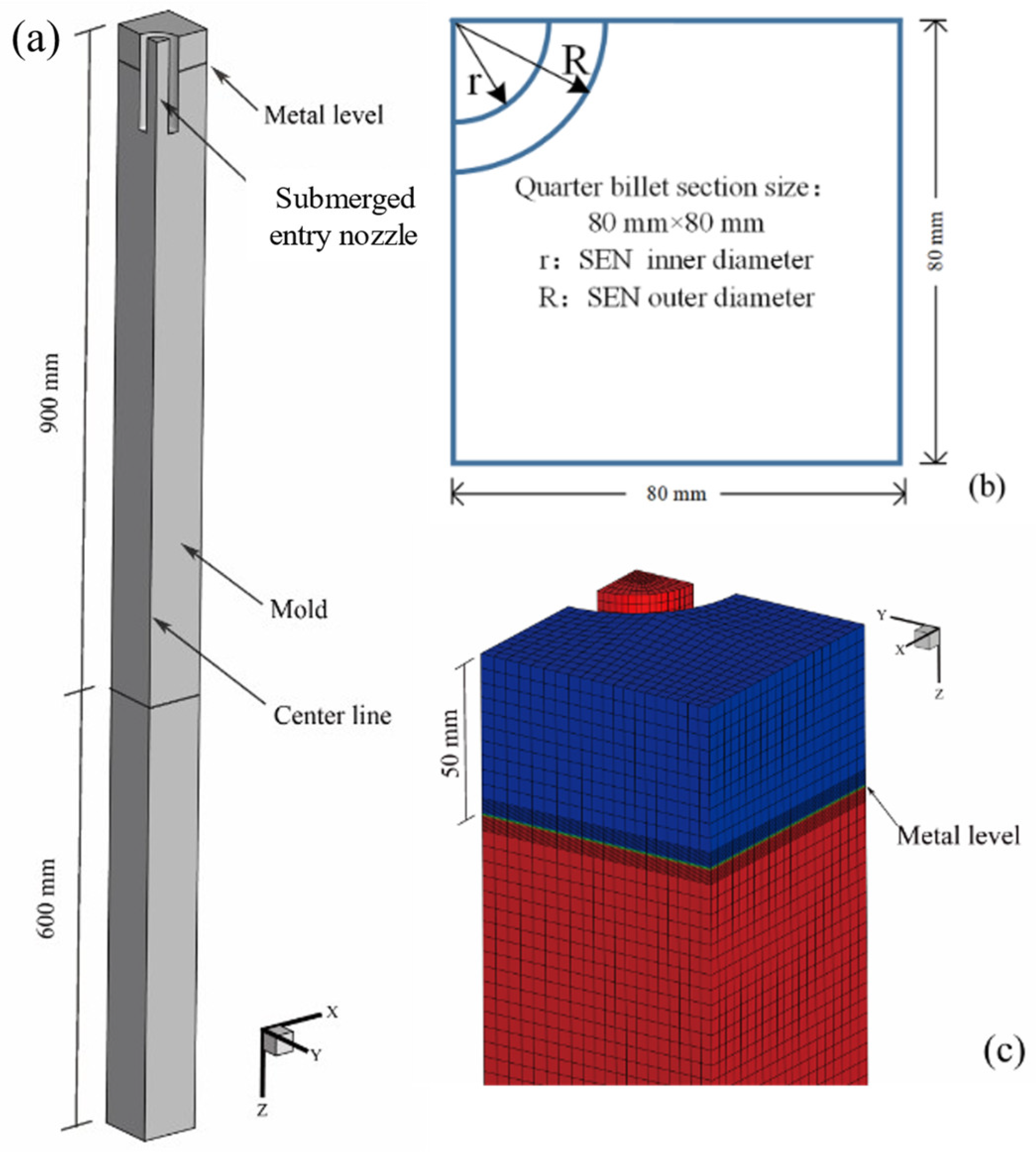
2.3. Model Domain and Boundary Conditions

Figure 1 shows the model domain and the computational grid used for the simulations. A straight-through SEN was adopted, as well as a billet mold with a section of 160 mm × 160 mm and a length of 900 mm. The mold’s outlet was extended by 600 mm to ensure the full development of turbulence. As shown in Figure 1a, a three-dimensional mold of a 1/4 model was built considering the symmetry of the model. The number of grids and the calculation time were significantly reduced with guaranteed calculation accuracy. Taking into account the influence of slag on the steel–slag interface, a slag layer of 50 mm was added to the top of the molten steel, and the grid of the steel–slag interface was encrypted to improve the simulation accuracy, as shown in Figure 1c.
The SEN was located in the upper part of the mold, and molten steel was poured through the velocity-inlet boundary based on a mass balance with the casting speed.
v i n l e t = v o u t l e t A o u t l e t A i n l e t = v z
v x = v y = 0
where vinlet is the inlet velocity of steel; voutlet is the casting speed; Ainlet and Aoutlet are the areas of the SEN inlet and mold outlet, respectively; and vx, vy, and vz are the velocity components of the inlet velocity in the x, y, and z directions, respectively.
The turbulence parameter was set to k and ε, calculated according to the empirical formula.
k = 0.01 v i n l e t 2
ε = k 1.5 D S E N
where DSEN is the diameter of the SEN outlet.
The physical parameters of the molten steel and the slag are shown in Table 1. The absorption of the slag’s composition and inclusions in the molten steel were not considered to facilitate the calculation. Based on the composition of slag and molten steel, the interfacial tension between the molten steel and slag was calculated to be 1.35 N/m [31].
A mass flow outlet condition was applied to the bottom of the domain at the mold’s exit. The liquid level of the billet mold was assumed to be in a fixed and free-slip condition. Additionally, all mold walls were assumed to be stationary and non-slipping. Unsteady simulations were selected for describing the movement of molten steel in the mold due to the time-varying flow field in the mold. In the present work, the time step for the calculation was 0.001 s.
The computational domain was dissected using a hexahedral mesh. The finite volume method was employed to discretize the conservation equations, and the Semi-Implicit Method for Pressure-Linked Equations (SIMPLE) algorithm was used to complete a coupled calculation of pressure and velocity. The least squares cell-based and PRESTO! algorithms were used to identify differences in gradients and pressure terms, respectively. When the residuals of the energy equation were lower than 10 × 10−6, and the residuals of the other physical variables were less than 10 × 10−3, the calculations could be regarded as converging.

3. Results and Discussion

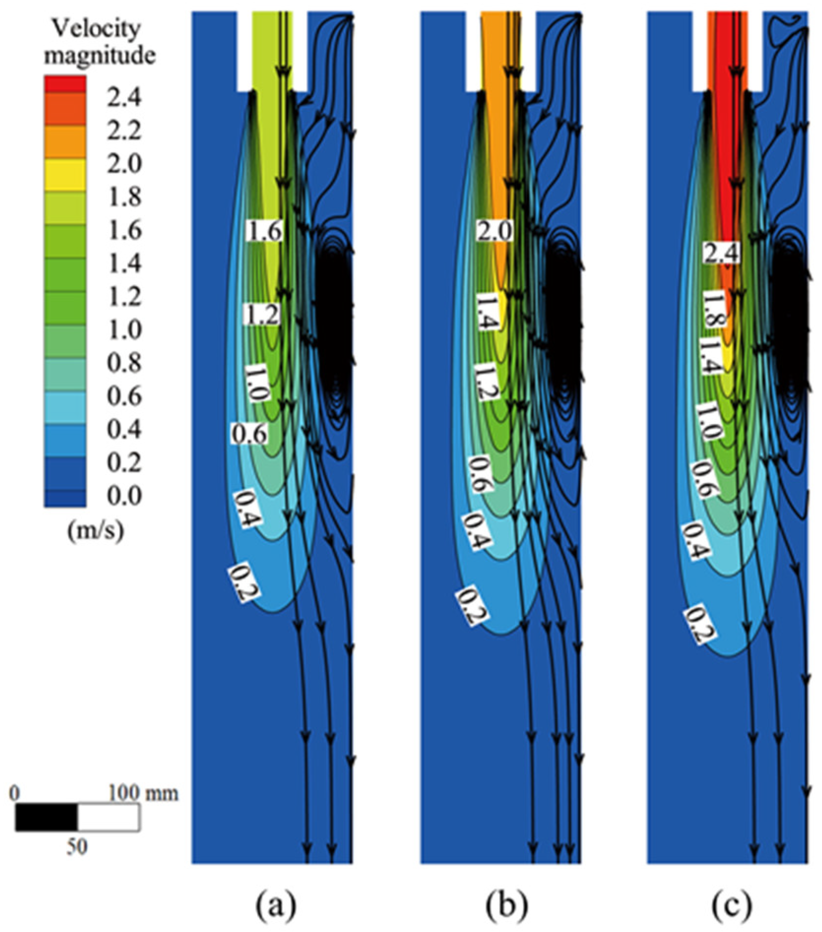
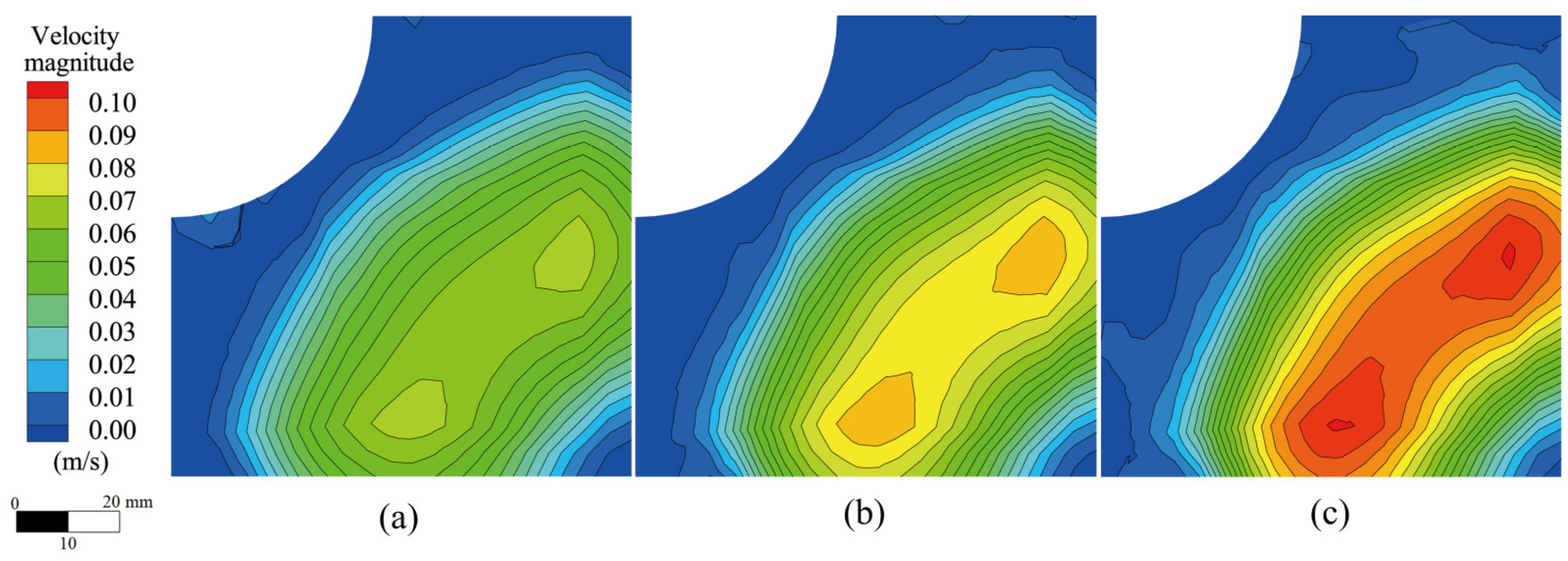
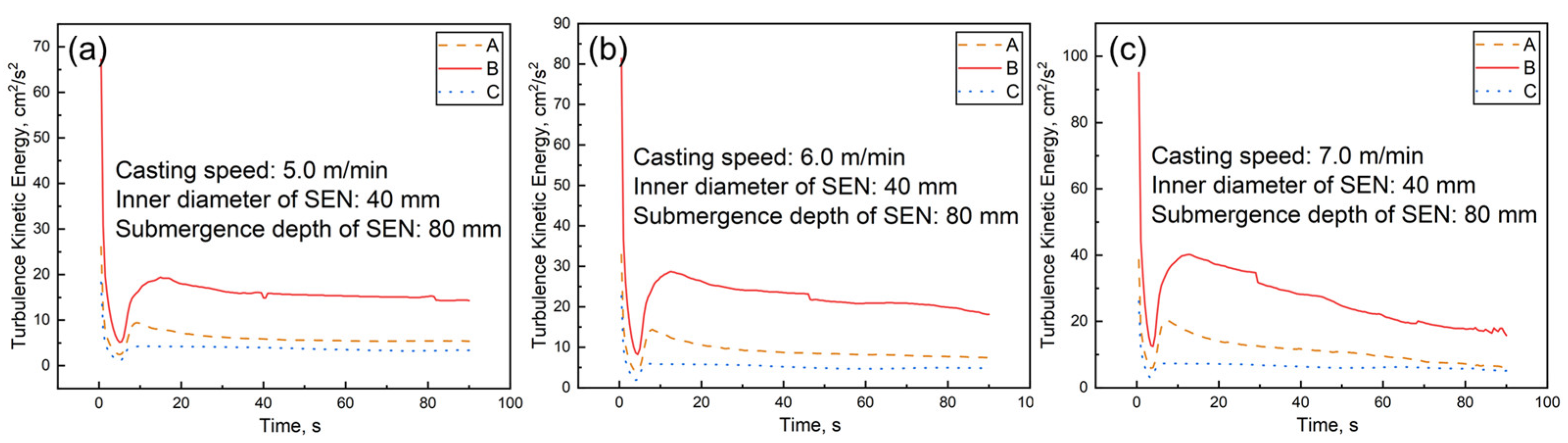
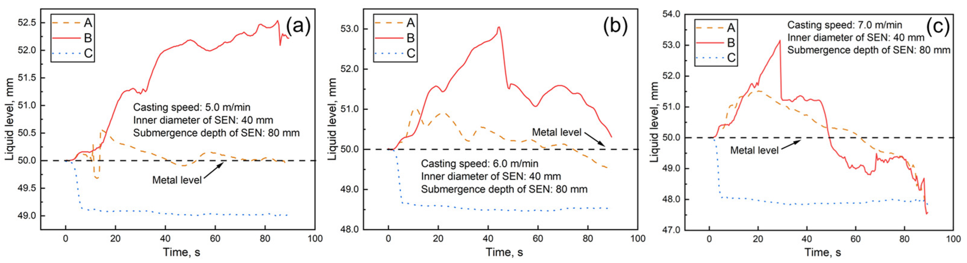
3.1. Effects of Casting Speeds

Symmetrical-plane flow fields in the mold at different casting speeds are exhibited in Figure 2, where the SEN depth was 80 mm and the inner diameter was 40 mm. The main stream of molten steel flowed to the bottom of the mold after passing through the straight-through SEN, and its jet velocity gradually decreased along the impact direction. The molten steel flow was fully developed, as there was more space in the vertical direction of the mold. The stream gradually diverged towards the mold wall during the development process, and the radial velocity of the molten steel declined alongside this increase in divergence. Although the throughputs of molten steel by mold (1.92, 2.30, and 2.69 m3/h for 5.0, 6.0, and 7.0 m/min casting speeds, respectively) increased alongside an increase in casting speed, this had only a minor effect on the speed of the molten steel in the low-flow-velocity area of the mold as well as on the flow pattern of the molten steel.
The molten steel streamline diagram shows that jet flows caused the inner wall of the lower part of the mold to split either downward or upward. The upward flow to the meniscus flowed back along the upper wall, leading to a disturbance in the liquid level. Affected by the Bernoulli effect, the slower surface flow was carried back to the SEN, producing a raceway with a new jet flow. This raceway expanded with casting speed, which resulted in a deeper impact depth and higher liquid level. The flow pattern in the mold was a single-roll flow (SRF), and the raceway was mainly distributed in the middle and upper parts of the mold. The downward flow followed the direction of the continuous casting and continued to move downward, evolving fully developed turbulence.
The impact depth, which is a crucial indicator in determining the floating of inclusions in the mold, is defined as the distance from the meniscus to the location where the molten steel velocity on the mold’s central axis matches the casting speed. When the impact depth was excessively deep, inclusions are captured by the shell, making it difficult for them to float, and the liquid level activity was weakened and developed a difficulty melting slag. In contrast, slag entrapment and other problems appeared at shallow impact depths. As shown in Table 2, when the inner diameter of the SEN was 40 mm, and the immersion depth was 80 mm, changes in casting speed had little effect on jet impact depths or raceway center positions. When the casting speed was increased from 5.0 to 7.0 m/min, the impact depth and the position of the raceway center were located near 316 and 352 mm, indicating that neither were sensitive to the change in casting speed.
Figure 3 reveals the distribution of the liquid level velocity of molds at different casting speeds. The average liquid level flow velocities were 0.037, 0.041, and 0.508 m/s for the casting speeds of 5.0, 6.0, and 7.0 m/min, respectively, while the maximum flow velocities were 0.067, 0.081, and 0.100 m/s, respectively. In addition, the flow of molten steel was faster in the middle of the liquid level than in the outer wall or corner of the SEN. The high-speed area of the liquid level kept growing as the casting speed rose, and the area of the dead zone kept decreasing but could not easily be eliminated.
The molten steel’s behavior varied from position to position at the liquid level. Generally, the molten steel’s activity at the center of the liquid level was much faster than at the corner of the mold. Turbulence kinetic energy and liquid level fluctuation were critical indexes of level stability. Three typical data sampling points were selected at the liquid level, according to the simulation results, to analyze the molten steel behavior at the mold’s steel–slag interface, as shown in Figure 4.
Figure 5 shows the changes to turbulent kinetic energy at the liquid level alongside changes to casting speed. Overall, the turbulent kinetic energy strengthened with the rise of casting speed. The turbulent kinetic energy at the middle of the liquid level was substantially stronger than at the corners. Based on the jet theory, as the initial kinetic energy of a jet increases, the degree of disturbance from the jet to the surrounding fluid also rises. Therefore, a boost in casting speed results in a stronger turbulent kinetic energy in the raceway, but flow is commonly weaker at the mold’s corners because of the wall effect, which is consistent with the results in Figure 3.
An increase in liquid level velocity and turbulent kinetic energy was directly reflected in an increase in liquid level fluctuation. The fluctuation of liquid levels at different casting speeds is exhibited in Figure 6. The maximum fluctuation of the liquid level at 5.0, 6.0, and 7.0 m/min were 2.54, 3.06, and 5.64 mm, respectively. Higher casting speeds caused the liquid level disturbance to widen and the liquid level to fluctuate more drastically at each position. In practice, liquid level fluctuation is required to be controlled within 3.0 mm to improve the quality of billet. However, level fluctuation was excessive when casting speeds were 6.0 and 7.0 m/min, which improved the opportunity for slag entrapment significantly.
In summary, while the flow patterns of the mold’s flow field at different casting speeds were identical, and the liquid level velocity was within a reasonable range, the liquid level fluctuations at 6.0 and 7.0 m/min casting speeds were overly wide, resulting in slag entrapment and affecting the final product quality. Relatively, the impact depth of molten steel at a 5.0 m/min casting speed was the shallowest, which may have driven the high-temperature area in the mold to move up, and the fluctuation range of the liquid level was also in an ideal state. Therefore, a 5.0 m/min casting speed is the best in these working conditions.

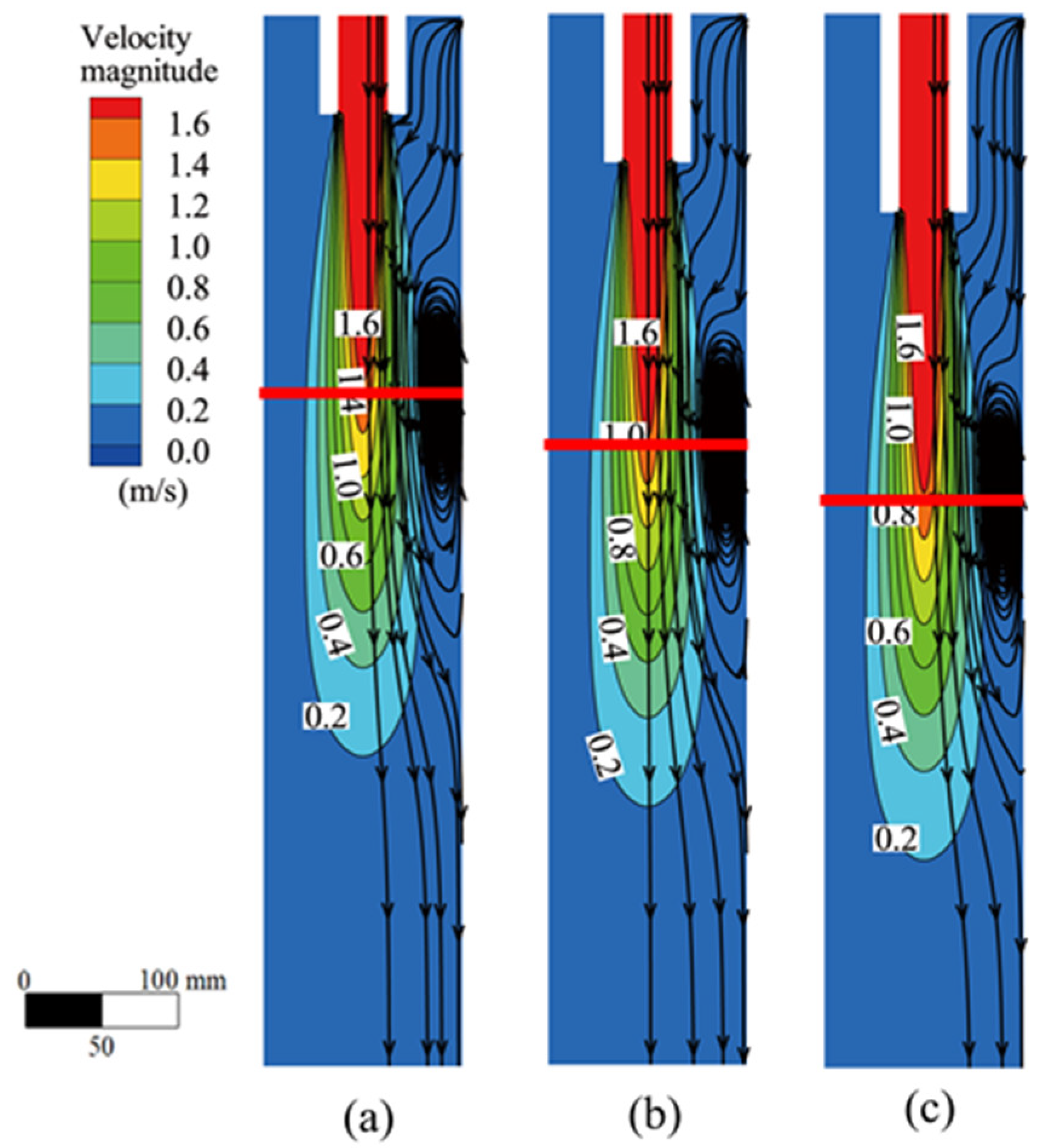
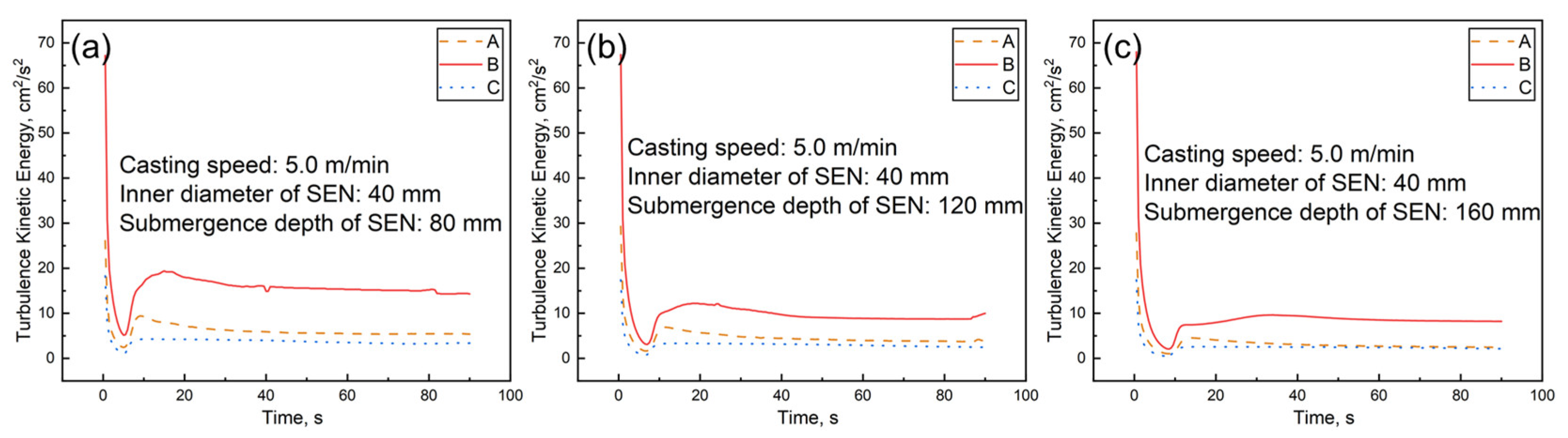
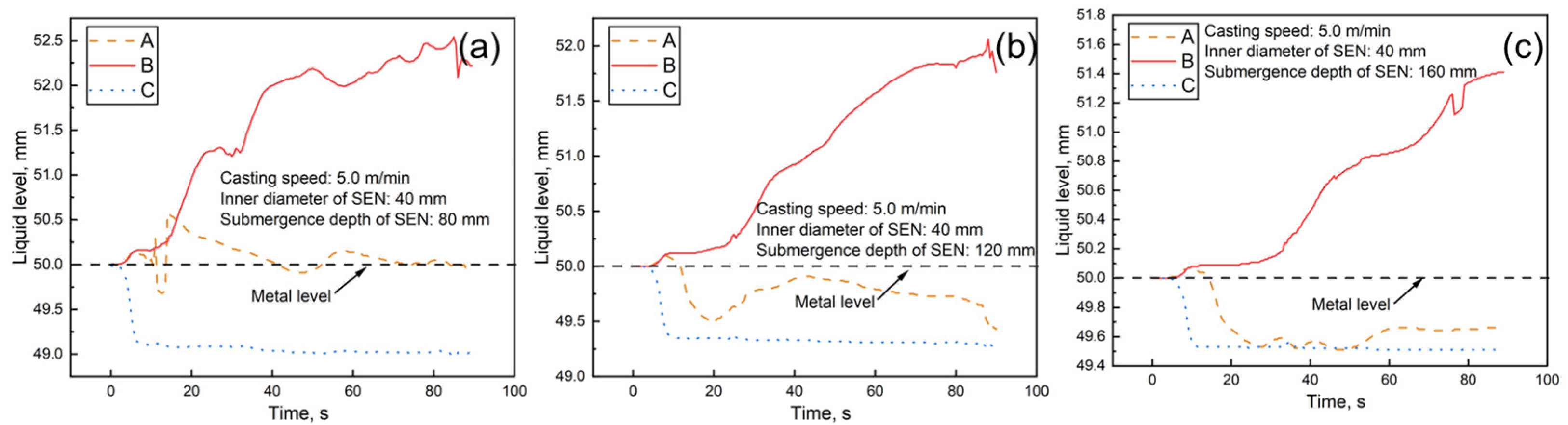
3.2. Effects of SEN Immersion Depths

The SEN immersion depth was also an important factor in determining the flow field of molten steel. The flow field at different immersion depths when the casting speed was 5.0 m/min and the inner diameter of the SEN was 40 mm is shown in Figure 7; the red horizontal line in the figure shows the position of the raceway center. An increase in the SEN immersion depth led to the overall downward movement of the high-velocity region, resulting in the downward movement of the impact depth and the raceway center position. However, there were no changes to the flow velocity of molten steel at the SEN outlet as there were for flow field characteristics. Once entering the mold, the jet impinged towards the bottom. Then, the weaker stream diverged towards the wall and flipped upward along the wall for backflow movement. The size of the raceway at different immersion depths was substantially homologous.
As shown in Table 3, with an increase in the immersion depth of the SEN, the impact depth and the position of the raceway center exhibited an obvious downward trend. The change in impact depth was slightly greater than that of the immersion depth, while the change in raceway center position was nearly consistent with the change in immersion depth. When the immersion depth was 160 mm, the jet impact depth and the raceway center position reached their deepest points.
The depth of the jet impingement and the position of the raceway were closely related to the molten steel velocity in the mold. The disturbance of the liquid level tended to decline alongside a rise in the distance from the raceway to the liquid level. Figure 8 exhibits the distribution of the liquid level flow velocity in the mold under different immersion depths. The change in immersion depth from 80 mm to 160 mm had a crucial influence on liquid level velocity. With an increase in immersion depth, the maximum flow velocity of the liquid level decreased continuously. The maximum flow velocities at immersion depths of 80, 120, and 160 mm were 0.066, 0.054, and 0.045 m/s, respectively. When the immersion depth was 160 mm, the maximum flow velocity of the liquid level was 32% lower than when the immersion depth was 80 mm. Therefore, compared with the effects of casting speed, an increase in immersion depth has a greater effect on reducing flow velocity.
As a result of the downward movement of the impact depth and raceway, the area of the dead zone at the corner was constantly expanding. The temperature drop at the corner of the billet was too steep under the effects of two-dimensional heat transfer and entered the low-temperature brittle zone, resulting in corner cracks. Moreover, the renewal of molten steel on the corner’s surface was slow, which was not conducive to the slag’s descent into the channel between the mold wall and the primary billet shell, and weakened the billet’s quality.
The liquid level’s turbulent kinetic energy distribution is illustrated in Figure 9. The minimum amount of turbulent kinetic energy appeared at the corner of the mold, which indicates that the fluidity of the molten steel was poor and that inclusions tended to accumulate. Nevertheless, the molten steel flow in the middle of the liquid level was completely developed, which is conducive to improving the quality of the billet.
Liquid level fluctuation was the dominant index for measuring the fluidity of a flow field in the upper part of a mold. In contrast, the longitudinal crack index of a slab increased with a rise in liquid level fluctuation. The fluctuation of the liquid level at different immersion depths is exhibited in Figure 10. The maximum fluctuation values were 2.54, 2.06, and 1.41 mm at immersion depths of 80, 120, and 160 mm, respectively, while the fluctuation decreased by 19% and 32%. This indicates that the change in immersion depth greatly influenced the liquid level fluctuation; the collision point between the jet and the wall was closer to the liquid level when the immersion depth was shallower. Subsequently, there was less energy loss from kinetic energy being converted into gravitational potential energy during the rising process of the jet, and the raceway area was closer to the free surface, leading to a more significant liquid level fluctuation.
The following formula is the expression for upstream momentum:
F = ρ Q V m ( 1 sin α ) 4 D
where, F is the characteristic value of upstream momentum, ρ is the molten steel density, Q is the outlet flow, Vm is the velocity at which the stream reaches the narrow surface, and α is the impact angle of the stream.
It was determined using this formula that the kinetic energy of the upstream flow and the liquid level fluctuation decreased with the enhancement of the SEN immersion. This was performed on the premise of determining the casting speed and SEN angle.
To sum up, when the casting speed was 5.0 m/min and the inner diameter of the SEN was 40 mm, the maximum flow velocity of the liquid level was reasonable at different immersion depths. When the liquid level fluctuated under 3.0 mm, slag entrapment on the liquid level had little effect. Therefore, without considering slag entrapment, immersion depth can be reduced to intensify liquid level disturbance and, thus, improve the melting rate of slag. From the perspective of impact depth, an immersion depth of 80 mm is also more conducive to the upward movement of the high-velocity zone and the promotion of inclusion floating. Consequently, considering the melting rate of the slag and the efficiency of inclusion removal, an immersion depth of 80 mm is more suitable.

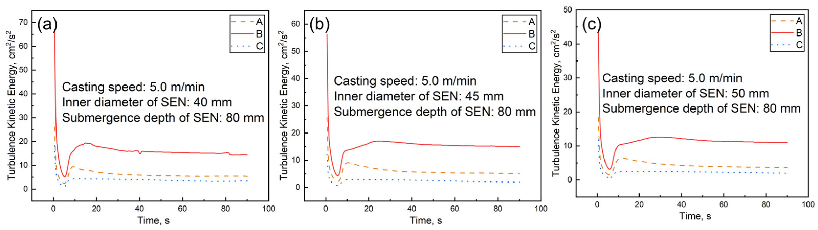
3.3. Effect of SEN Inner Diameters

Figure 11 compares the flow field of the symmetrical plane of the mold with different SEN inner diameters when the casting speed was 5.0 m/min and the SEN immersion depth was 80 mm. The velocity of the molten steel jet at the outlet of SEN slowed down from 1.6 m/s to 1.2 m/s, and the main stream of molten steel thickened with the increased SEN inner diameter. Although the longitudinal space was compressed and the raceway tended to decline, the flow pattern of the molten steel showed a minor change. The proper enhancement of the inner diameter promises to reduce the initial velocity of the jet and the scouring of the stream on the solidified shell on the mold wall, which is conducive to high-speed casting.
With the expansion of the inner diameter of the SEN, the jet’s impact depth gradually deepened while the formation position of the raceway center moved up (Table 4). When the inner diameter of the SEN was 50 mm, its impact depth reached its deepest point at 362 mm, and the formation position of the raceway was the nearest to the liquid level, at only 337 mm.
Figure 12 exhibits the flow field of the liquid level at different inner diameters of the SEN. When the inner diameter of the SEN was 40, 45, and 50 mm, the maximum flow rate of the liquid level was 0.066, 0.057, and 0.048 m/s, respectively. A decrease in the liquid level flow velocity also directly led to the expansion of the dead zone area at the corner of the mold, where the inclusion collided and polymerized. With the same molten steel flux, the expansion of the SEN inner diameter caused the raceway to move up, but the increase in impact depth decreased the kinetic energy of the rising and backflow significantly and subsequently slowed down the liquid level flow.
The distribution of turbulent kinetic energy at different SEN inner diameters is illustrated in Figure 13. The maximum turbulent kinetic energy at each position of the liquid level decreased with an increase in the SEN inner diameter. It reached its maximum when the inner diameter was 40 mm, and its behavior law was similar to the liquid level flow velocity. The wall effect influenced molten steel on the outer wall and at the corner of the SEN, and turbulence had difficulty developing.
Figure 14 reveals the fluctuation of the liquid level at different SEN inner diameters, showing that the fluctuation amplitude of the liquid level decreased with an increase in the SEN inner diameter. The maximum fluctuation of SEN liquid levels at 40, 45, and 50 mm inner diameters was 2.54, 1.98, and 1.40 mm, respectively. As a result of the shallow immersion depth, the “Bernoulli effect” was slightly active near the SEN wall. Still, the maximum fluctuation of the liquid level at different inner diameters was within a reasonable range.
In general, when the casting speed was 5.0 m/min and the immersion depth was 80 mm, an enhancement of the SEN inner diameter may have brought about an increase in its impact depth and a rising of the raceway. However, the molten steel flow velocities and fluctuations were consistently within a reasonable range without considering slag entrapment. Therefore, to accelerate the slag’s melting rate and prevent the solidified shell from thinning at the lower part of the mold, a SEN with an inner diameter of 40 mm is more conducive to high-speed casting.

4. Conclusions

In this paper, the influences of casting speed, SEN immersion depth, and SEN inner diameter on the flow field in a mold at an ultrahigh casting speed were studied using simulation. The main research indicators included the symmetrical plane flow field of the mold, its liquid level velocity, its turbulent kinetic energy, and the fluctuation of the liquid level. The main conclusions were as follows:
(1)
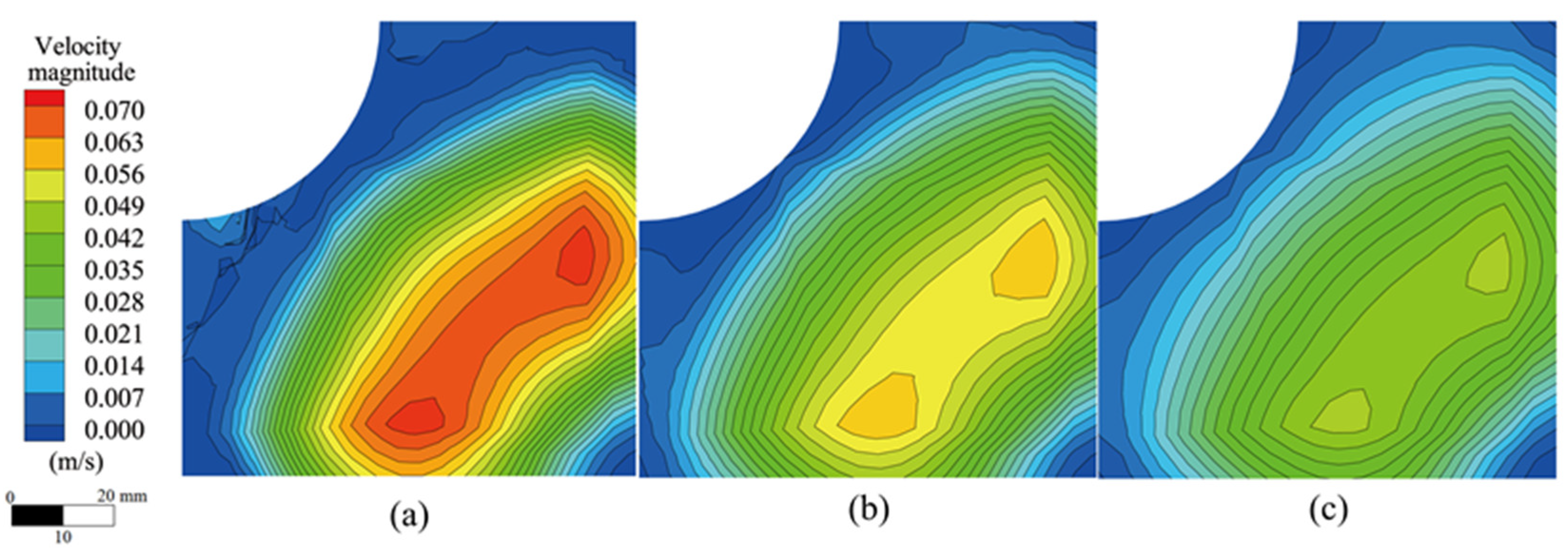
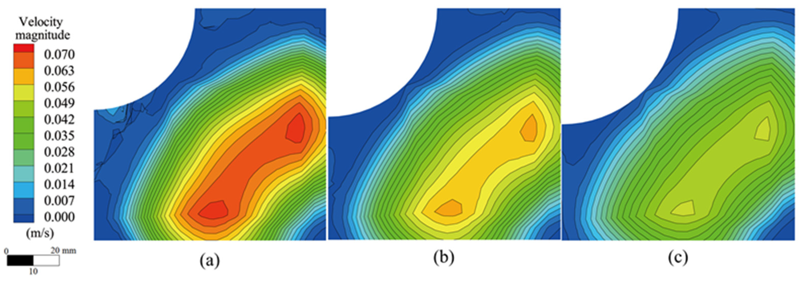
The mold’s flow field patterns at different casting parameters were SRF, and there was no obvious change. The position where the liquid level flow velocity and fluctuation amplitude were the largest is concentrated in the middle of the liquid level. The turbulence of molten steel at the corner of the mold is difficult to develop, which can easily cause inclusion accumulation.
(2)
Changes to the casting speed had a minimal influence on the impact depth of the molten steel jet and the position of the raceway center. The velocity and fluctuation amplitude of the liquid level increased with the acceleration of the casting speed. When the casting speed was 7.0 m/min, the maximum velocity of the liquid level reached 0.1 m/s, and the maximum fluctuation value of the liquid level reached 5.64 mm.
(3)
When the SEN immersion depth deepened, the flow field in the mold moved downward as a whole, and changes to the impact depth and raceway center position were close to the shift of the immersion depth. When the SEN immersion depth was 160 mm, the liquid level flow velocity and liquid level fluctuation reached their minimum points of 0.066 m/s and 2.54 mm, respectively.
(4)
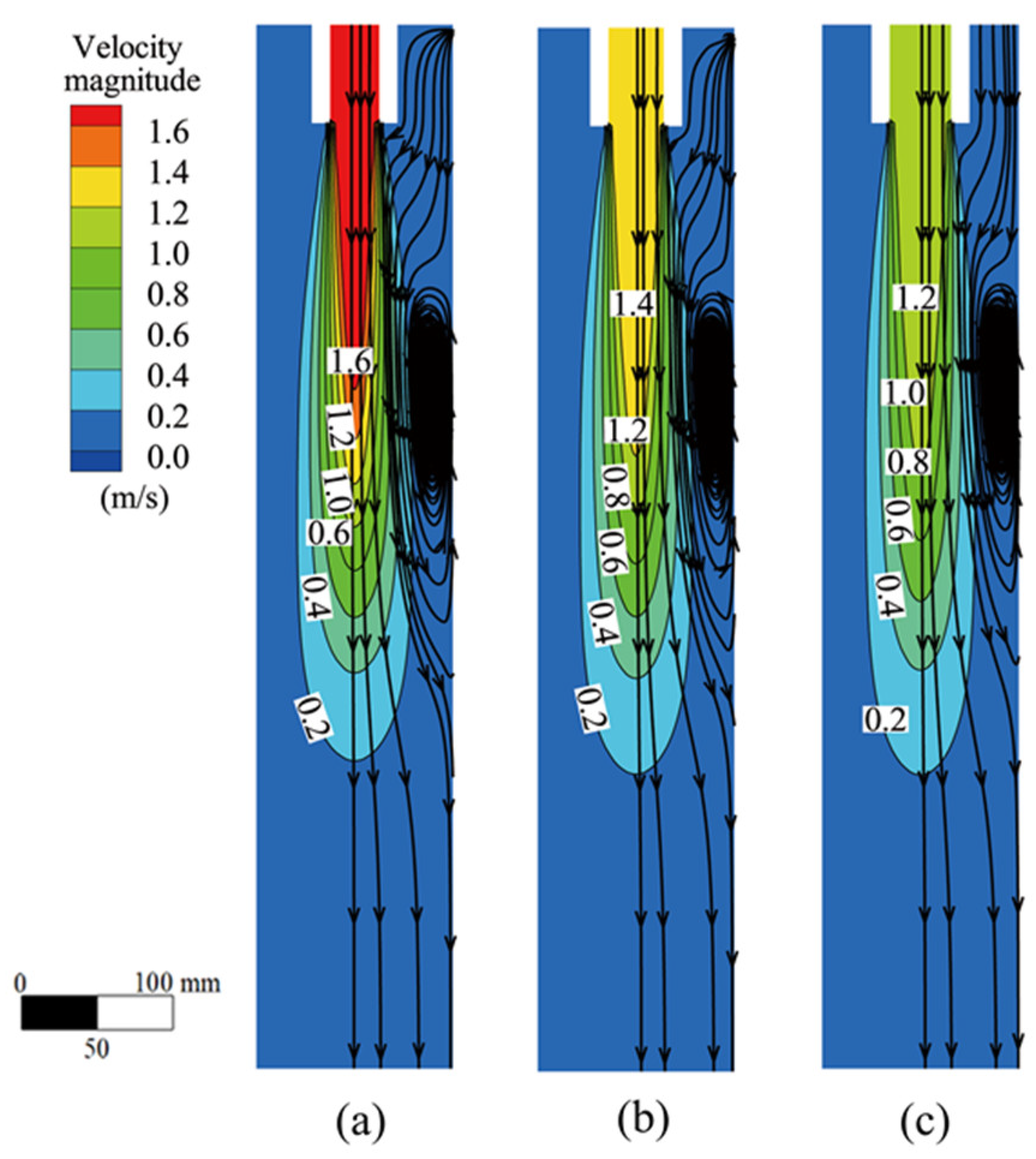
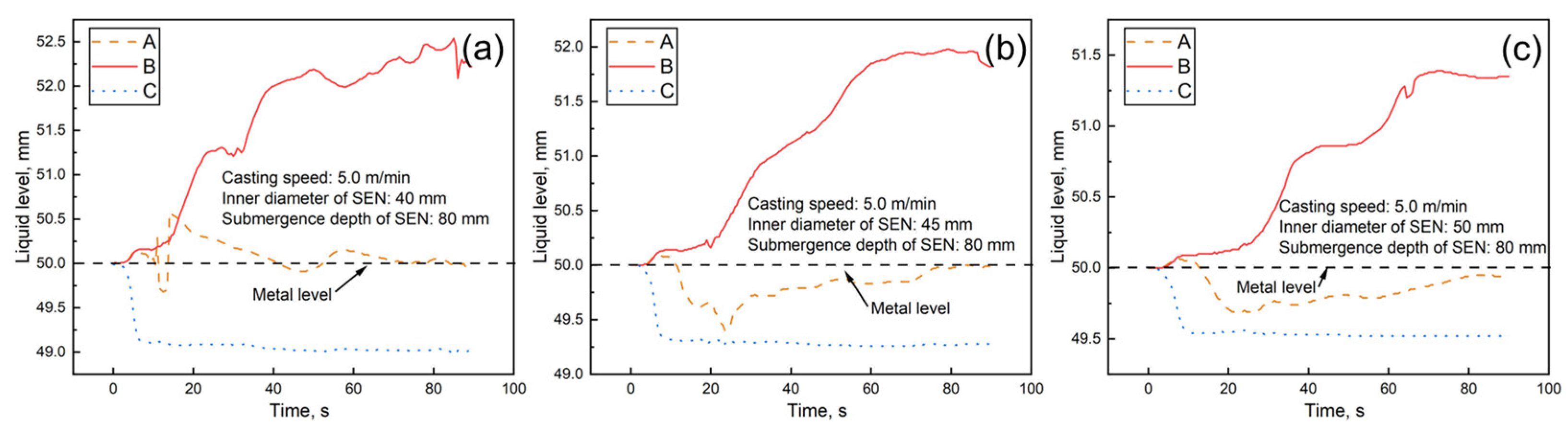
Although increasing the inner diameter of the SEN deepened the impact depth, it effectively weakened the initial velocity of the molten steel jet and reduced the scouring effect on the solidified shell. The main stream, after the inner diameter increased, also compressed the longitudinal space of the mold, reduced the overall area of the raceway, slowed down the liquid level disturbance, and facilitated high-speed casting. The velocity and fluctuation of molten steel at the liquid level also slowed down with the expansion of the inner diameter.
The direction of research into continuous casting technology is shifting towards ultrahigh-speed casting. In addition to the fundamental parameters of the SEN, further research on supporting facilities, such as electromagnetic systems, is necessary for the advancement of continuous casting.

Author Contributions

Conceptualization, D.Q. and Z.Z.; formal analysis, X.L. and X.X.; funding acquisition, Z.Z.; investigation, D.Q. and X.M.; methodology, D.Q. and X.X.; project administration, Z.Z.; software, M.L. and X.M.; validation, D.Q. and X.X.; visualization, M.L. and X.M.; writing—original draft, D.Q.; writing—review and editing, Z.Z. and X.X. All authors have read and agreed to the published version of the manuscript.

Funding

This work was funded by the Natural Science Foundation of the Shaanxi Province (Grant No.2021JLM-32).

Data Availability Statement

The data that support the findings of this study are available from the corresponding author upon reasonable request.

Acknowledgments

The authors are grateful to the Department of Science and Technology of Shaanxi Province and the China National Heavy Machinery Research Institute Co., Ltd. The authors thank Yifan Xv for English language editing.

Conflicts of Interest

The authors declare no conflict of interest.

References

  1. Wang, E.G.; He, J.C. Finite element numerical simulation on thermo-mechanical behavior of steel billet in continuous casting mold. Sci. Technol. Adv. Mater. 2001, 2, 257–263. [Google Scholar] [CrossRef]
  2. Hong, K.H.; Kim, C.S.; Cha, P.R.; Yoon, J.K. A numerical analysis of fluid flow, heat transfer and solidification in the bending-type square billet continuous casting process. Met. Mater. Int. 2002, 8, 111–117. [Google Scholar] [CrossRef]
  3. Yang, J.; Chen, D.F.; Long, M.J.; Duan, H.M. Transient flow and mold flux behavior during ultra-high speed continuous casting of billet. J. Mater. Res. Technol. 2020, 9, 3984–3993. [Google Scholar] [CrossRef]
  4. Xu, P.; Chen, D.F.; Du, Y.Z.; Yu, H.S.; Long, M.J.; Liu, P.; Duan, H.M.; Yang, J. Hydraulic modeling on flow behavior in high-speed billet continuous casting mold considering hydrostatic pressure and solidified shell. Metals 2020, 10, 1226. [Google Scholar] [CrossRef]
  5. Abouelazayem, S.; Glavinić, I.; Wondrak, T.; Hlava, J. Flow control based on feature extraction in continuous casting process. Sensors 2020, 20, 6880. [Google Scholar] [CrossRef]
  6. Chow, C.; Samarasekera, I.; Walker, B.; Lockhart, G. High speed continuous casting of steel billets: Part 2: Mould heat transfer and mould design. Ironmak. Steelmak. 2002, 29, 61–69. [Google Scholar] [CrossRef]
  7. Ho, Y.H.; Chen, C.H.; Hwang, W.S. Analysis of molten steel flow in slab continuous caster mold. ISIJ Int. 1994, 34, 255–264. [Google Scholar] [CrossRef]
  8. Li, B.; Lu, H.B.; Zhong, Y.B.; Ren, Z.M.; Lei, Z.S. Numerical simulation for the influence of EMS position on fluid flow and inclusion removal in a slab continuous casting mold. ISIJ Int. 2020, 60, 1204–1212. [Google Scholar] [CrossRef]
  9. Guthrie, R.I.; Isac, M.M. Continuous casting practices for steel: Past, present and future. Metals 2022, 12, 862. [Google Scholar] [CrossRef]
  10. Chen, W.; Zhang, L.F. Effects of interphase forces on multiphase flow and bubble distribution in continuous casting strands. Metall. Mater. Trans. B 2021, 52, 528–547. [Google Scholar] [CrossRef]
  11. Wang, X.; Zheng, S.G.; Liu, Z.H.; Zhu, M.Y. Numerical simulation on multiple physical fields behaviors in billet continuous casting with different stirrer positions. Steel Res. Int. 2019, 91, 1900415. [Google Scholar] [CrossRef]
  12. Wu, H.D.; Chen, J.G.; Peng, Z. Simulation of the flow-heat transfer process in billet mold and analysis of the billet rhomboidity phenomenon. Appl. Therm. Eng. 2020, 173, 115235. [Google Scholar] [CrossRef]
  13. Hua, C.J.; Wang, M.; Bao, Y.P. Effect of nozzle clogging on the fluid flow pattern in a billet mold with particle image velocimetry technology. Metall. Mater. Trans. B 2020, 51, 2871–2881. [Google Scholar] [CrossRef]
  14. Ren, B.Z.; Chen, D.F.; Wang, H.D.; Long, M.J. Numerical analysis of coupled turbulent flow and macroscopic solidification in a round bloom continuous casting mold with electromagnetic stirring. Steel Res. Int. 2015, 86, 1104–1115. [Google Scholar] [CrossRef]
  15. Cho, S.M.; Thomas, B.G.; Kim, S.H. Effect of nozzle port angle on transient flow and surface slag behavior during continuous steel-slab casting. Metall. Mater. Trans. B 2019, 50, 52–76. [Google Scholar] [CrossRef]
  16. Lee, J.H.; Han, S.; Cho, H.J.; Park, I.S. Numerical and experimental study of the meniscus vortex core in a water model of continuous casting mold. Metall. Mater. Trans. B 2021, 52, 178–189. [Google Scholar] [CrossRef]
  17. Xu, P.; Zhou, Y.Z.; Chen, D.F.; Long, M.J.; Duan, H.M. Optimization of submerged entry nozzle parameters for ultra-high casting speed continuous casting mold of billet. J. Iron Steel Res. Int. 2022, 29, 44–52. [Google Scholar] [CrossRef]
  18. Michelic, S.K.; Bernhard, C. Significance of nonmetallic inclusions for the clogging phenomenon in continuous casting of steel—A review. Steel Res. Int. 2022, 93, 2200086. [Google Scholar] [CrossRef]
  19. Kholmatov, S.; Takagi, S.; Jonsson, L.; Jönsson, P.; Yokoya, S. Effect of nozzle angle on flow field and temperature distribution in a billet mould when using swirl flow. Steel Res. Int. 2008, 79, 31–39. [Google Scholar] [CrossRef]
  20. Gan, M.J.; Pan, W.J.; Wang, Q.Q.; Zhang, X.B.; He, S.P. Effect of exit shape of submerged entry nozzle on flow field and slag entrainment in continuous casting mold. Metall. Mater. Trans. B 2020, 51, 2862–2870. [Google Scholar] [CrossRef]
  21. Lee, W.H.; Yi, K.W. Relationship between fluid flow stability and submerged entry nozzle port angle in a conventional slab continuous-casting mold. Met. Mater. Int. 2021, 27, 4168–4181. [Google Scholar] [CrossRef]
  22. Vakhrushev, A.; Kharicha, A.; Liu, Z.; Wu, M.; Ludwig, A.; Nitzl, G.; Tang, Y.; Hackl, G.; Watzinger, J. Electric current distribution during electromagnetic braking in continuous casting. Metall. Mater. Trans. B 2020, 51, 2811–2828. [Google Scholar] [CrossRef]
  23. Fei, P.; Min, Y.; Liu, C.J.; Jiang, M.F. Effect of continuous casting speed on mold surface flow and the related near-surface distribution of non-metallic inclusions. Int. J. Miner. Metall. Mater. 2019, 26, 186–193. [Google Scholar] [CrossRef]
  24. Yu, Z.; Zhang, Z.Q.; Ren, Z.M. Effect of flow control mold on flow field during high-speed continuous casting. Adv. Manuf. 2017, 5, 271–278. [Google Scholar] [CrossRef]
  25. Li, X.T.; Zhang, Z.H.; Lv, M.; Fang, M.; Liu, K.L. Numerical simulation of the fluid flow, heat transfer, and solidification in ultrahigh speed continuous casting billet mold. Steel Res. Int. 2022, 93, 2100673. [Google Scholar] [CrossRef]
  26. Li, X.T.; Zhang, Z.H.; Lv, M.; Fang, M.; Ma, S.B.; Li, D.L.; Xi, X.F. Effect of mold electromagnetic stirring on metallurgical behavior in ultrahigh speed continuous casting billet mold. Steel Res. Int. 2023. [Google Scholar] [CrossRef]
  27. Li, Z.; Wang, E.G.; Zhang, L.T.; Xu, Y.; Deng, A.Y. Influence of vertical electromagnetic brake on the steel/slag interface behavior in a slab mold. Metall. Mater. Trans. B 2017, 48, 2389–2402. [Google Scholar] [CrossRef]
  28. Jiang, P.; Yang, J.; Zhang, T.; Xu, G.J.; Liu, H.J.; Zhou, J.J.; Qin, W. Optimization of flow field in slab continuous casting mold with medium width using high temperature measurement and numerical simulation for automobile exposed panel production. Metals 2019, 10, 9. [Google Scholar] [CrossRef]
  29. Wang, Y.; Fang, Q.; Zhang, H.; Zhou, J.A.; Liu, C.S.; Ni, H.W. Effect of argon blowing rate on multiphase flow and initial solidification in a slab mold. Metall. Mater. Trans. B 2020, 51, 1088–1100. [Google Scholar] [CrossRef]
  30. Sun, X.H.; Li, B.; Lu, H.B.; Zhong, Y.B.; Ren, Z.M.; Lei, Z.S. Steel/slag interface behavior under multifunction electromagnetic driving in a continuous casting slab mold. Metals 2019, 9, 983. [Google Scholar] [CrossRef]
  31. Cramb, A.W.; Jimbo, I. Calculation of the interfacial properties of liquid steel–slag systems. Steel Res. 1989, 60, 157–165. [Google Scholar] [CrossRef]
Figure 1. (a) Model domain, (b) billet section, and (c) computational grid in the simulations.
Metals 13 00964 g001
Figure 2. Flow field on the symmetrical plane of the mold at different casting speeds. (a) 5.0 m/min; (b) 6.0 m/min; (c) 7.0 m/min.
Metals 13 00964 g002
Figure 3. Effect of casting speed on flow field at the liquid level of the mold. (a) 5.0 m/min; (b) 6.0 m/min; (c) 7.0 m/min.
Metals 13 00964 g003
Figure 4. Data collection points for the mold’s liquid level.
Metals 13 00964 g004
Figure 5. Effect of casting speed on turbulent kinetic energy at the mold’s liquid level. (a) 5.0 m/min; (b) 6.0 m/min; (c) 7.0 m/min.
Metals 13 00964 g005
Figure 6. Effect of casting speeds on the mold’s liquid level. (a) 5.0 m/min; (b) 6.0 m/min; (c) 7.0 m/min.
Metals 13 00964 g006
Figure 7. Flow field at the symmetrical plane of the mold at different immersion depths. (a) 80 mm; (b) 120 mm; (c) 160 mm.
Metals 13 00964 g007
Figure 8. The effect of immersion depth on the flow field at the liquid level of the mold. (a) 80 mm; (b) 120 mm; (c) 160 mm.
Metals 13 00964 g008
Figure 9. Effect of immersion depth on the turbulent kinetic energy of a mold’s liquid level. (a) 80 mm; (b) 120 mm; (c) 160 mm.
Metals 13 00964 g009
Figure 10. Effect of immersion depth on the mold’s liquid level. (a) 80 mm; (b) 120 mm; (c) 160 mm.
Metals 13 00964 g010
Figure 11. Flow field on the symmetrical plane of the mold at different inner diameters. (a) 40 mm; (b) 45 mm; (c) 50 mm.
Metals 13 00964 g011
Figure 12. The effect of inner diameter on the flow field at the liquid level of the mold. (a) 40 mm; (b) 45 mm; (c) 50 mm.
Metals 13 00964 g012
Figure 13. Effect of inner diameter on turbulent kinetic energy of the mold’s liquid level. (a) 40 mm; (b) 45 mm; (c) 50 mm.
Metals 13 00964 g013
Figure 14. Effect of inner diameter on the mold’s liquid level. (a) 40 mm; (b) 45 mm; (c) 50 mm.
Metals 13 00964 g014
Table 1. Operation conditions of the billet continuous casting.
ParametersValues
Mold section (mm × mm)160 × 160
Effective length of mold (mm)900
Computational length of mold (mm)1500
Steel density (kg/m3)7200
Steel viscosity (Pa·s)0.0065
Slag density (kg/m3)2600
Slag viscosity (Pa·s)0.1
Thickness of slag layer (mm)50
Interfacial tension between molten steel and slag (N/m)1.35
Table 2. Effect of casting speed on impact depth and raceway center position of molten steel.
Casting Speeds (m/min)Impact Depth (mm)Distance from Raceway Center to Liquid Level (mm)
5.0315351
6.0316352
7.0317353
Table 3. Effect of immersion depth on the impact depth and raceway center position of molten steel.
Immersion Depth (mm)Impact Depth (mm)Distance from Raceway Center to Liquid Level (mm)
80315351
120362392
160412434
Table 4. Effect of inner diameter on the impact depth and raceway center position of molten steel.
Inner Diameters (mm)Impact Depth (mm)Distance from Raceway Center to Liquid Level (mm)
40315351
45343346
50362337
Disclaimer/Publisher’s Note: The statements, opinions and data contained in all publications are solely those of the individual author(s) and contributor(s) and not of MDPI and/or the editor(s). MDPI and/or the editor(s) disclaim responsibility for any injury to people or property resulting from any ideas, methods, instructions or products referred to in the content.

