Article

Die Design and Finite Element Analysis of Welding Seams during Aluminum Alloy Tube Extrusion

Department of Mechanical and Electro-Mechanical Engineering, National Sun Yat-sen University, Kaohsiung 804, Taiwan
*
Author to whom correspondence should be addressed.
Metals 2023, 13(5), 911; https://doi.org/10.3390/met13050911
Submission received: 10 April 2023 / Revised: 30 April 2023 / Accepted: 5 May 2023 / Published: 8 May 2023
(This article belongs to the Special Issue Sheet Metal Forming)

Abstract

:
Hollow tubes are generally manufactured using porthole die extrusion. A finite element software QForm is used to analyze the material flow of aluminum alloy A6061 tubes inside a specially designed porthole die during tube extrusion. High welding pressure and shorter transverse seam length are required for a sound product. Various extrusion conditions and die geometries and dimensions affect the bonding strength of the products. In this paper, the effects of die geometries on the welding pressure are discussed using the Taguchi method. The simulation results show that a higher welding pressure is obtained with a larger porthole radius, a larger welding chamber height, and a larger bearing length, while a larger bridge width increases the welding pressure slightly. For transverse seam lengths, a shorter transverse seam length can be obtained with a smaller porthole radius and a smaller welding chamber height, and a shorter bridge width and bearing length decrease the transverse seam length slightly. The transverse seam region and flow patterns are observed. Tube expanding tests were also conducted. From the expanding test results, it is known that the fracture position did not occur at the welding line and the bonding strength could reach up to 160 MPa.

1. Introduction

Due to increasing demands of light-weight structures, various tubes, such as round tubes, thin tubes, square tubes, and asymmetrical-shaped tubes, are widely applied in various industries. Most of them are manufactured by extrusion processes. According to different extrusion die design methods, extruded tubes are divided into seam tubes and seamless tubes. Various tubes with complicated geometry and dimensional accuracy are used in the automotive and bicycle industries. Different extrusion methods have been proposed, such as isothermal extrusion, half-solid-state extrusion, high speed extrusion, and equal-channel angular pressing, etc. Extrusion die design is crucial for a successful extrusion process [1]. In aluminum extrusion processes, friction behaviors at the workpiece/tooling interface are highly complex, which are affected by local temperature, relative velocity, contact pressure, geometry, and tooling surface roughness, etc. Wang et al. [2] and Wang and Yang [3] summarized the recent developments of the friction testing techniques for aluminum extrusion processes and detailed comparisons of these techniques. Among the existing friction testing techniques, the combination of extrusion friction tests and short sliding distance ball-on-disc tests were recommended.
In aluminum hot extrusion processes, many forming parameters such as extrusion ratio, ram velocity, and billet temperature affect the extrusion load and the mechanical properties or the microstructures of the extruded products. Marín et al. [4] investigated the influence of temperature in the extrusion process by finite element analysis. The required load and the maximum exit velocity were discussed considering different temperatures. The optimized values of the temperatures in the billet and die were obtained to achieve a good quality of the extruded products. Bandini et al. [5] used FE code QForm to predict the microstructure evolution in 6XXX aluminum alloys. Preliminary simulations were carried out to select optimal friction models and coefficients among the several formulations available in the code. The numerical results were compared to grid-based visioplasticity experiments. The optimized friction model and coefficient were then applied in a second series of simulations to develop a prediction model of microstructure evolution. The simulated grain size and shape of 6XXX aluminum alloys were compared with experimental observations to validate the numerical model. Chen et al. [6] investigated the effects of various forming conditions on the extrusion load and product shapes in multi-hole extrusion of aluminum alloy tubes numerically and experimentally. The finite element simulation results revealed that the most crucial process parameter is the number of holes and their locations on the extrusion die. Liu et al. [7,8] used finite element simulation to investigate the effects of ram speeds and billet temperatures on the extrusion load in magnesium alloy AZ31 extrusion with an X-shaped cross-section. The correlations between the process variables and the response of the extrusion temperature and the peak extrusion pressure were established from the finite element simulations and verified by experiments. Sikand et al. [9] conducted tube extrusion experiments of AM30 magnesium alloy using a porthole die and a conical die with a mandrel attached at the ram. They made comparisons of the microstructure and mechanical properties of the extruded tubes using the porthole die and conical die. The tubes fabricated using the porthole die showed significant refinement in microstructure with improved mechanical properties compared to the tubes fabricated using the conical die. However, the extrusion loads using the porthole die were higher compared to that using the conical die.
Transverse welds occur at the joint of the billet–billet parts in extrusion processes for continuous production. Transverse welds introduce a discontinuity at the weld interface in the extruded long tubes or rods. The strength at the transverse welds is much weaker compared to the mother metal, thus, the transverse welding regions have to be cut off after extrusion, which decreases the overall yield of the products. Therefore, the transverse welding length should be controlled as short as possible. Li et al. [10] investigated the formation and metal flow of transverse welds in aluminum extrusion processes using the finite element simulation. The simulation results revealed that inhomogeneous metal flow and a transverse welding pattern occurred. The design parameters influencing the transverse weld length were also discussed. Mahmoodkhani et al. [11] developed a mathematical model of hot extrusion processes of aluminum alloy circular bars and validated it by experiments. The transverse seam diagram and area percentage of two materials in the cross-sections of the tubes were inspected. The results showed that the transverse weld was significantly affected by the feeder geometry shape, but the effects of ram speed, billet material, and temperature on the transverse weld dimensions were negligible. Zhang et al. [12] experimentally and numerically investigated the extrusion transverse welds of 7N01 aluminum alloy hollow asymmetric square tubes. The transient extrusion process was simulated based on a finite element software HyperXtrude. The effects of the process parameters on the cross-sectional area percentage of the transverse seam were discussed. Bakker et al. [13] conducted a series of extrusion experiments of aluminum alloy hollow rectangular tubes using a porthole die and investigated the effects of the presence of a charge weld transition zone on the failure mode under tensile tests and local effective mechanical properties of the extrudate. The evolutionary geometry of the bonding plane was visualized by serial sectioning of the extrudate. They found that the mechanical performance was largely controlled by the oxide particle density at the charge weld boundary. Zhang et al. [14] investigated the transverse weld in 7N01 aluminum alloy hollow tubes used in high-speed trains by experimental analysis coupled with finite element simulations. Numerical models of transverse welds were also built to analyze the evolution of transverse welds. The influences of extrusion process parameters and die structure on the length of transverse welds were discussed. The transverse weld length was reduced effectively by adjusting the extrusion ratio, ram speed, height of baffle plate, and sinking depth of the port bridge.
Longitudinal welding seams are an intrinsic characteristic in the extrusion of hollow products using a porthole die. The bonding strength at the welding seams affected by the porthole die design dominates the whole material properties of the extrudate. Bakker et al. [15] investigated the occurrence of defects inside the extrudate in a direct hot extrusion process of AW-6060 and AW-6082 aluminum alloy billets with an obstacle at the center of the die. The effects of different geometries of the weld-chamber and the processing conditions on the quality of the welding seams were discussed. Through computer simulations, conditions related to welding seam formation were modelled and correlated with the experimental results. Kim et al. [16] investigated the effects of an improved porthole die on the welding pressure using finite element analysis of aluminum tube extrusion. The expanding test results showed that the welding strength of tubes extruded by the modified porthole die was improved compared to that made by a conventional porthole die. Zhao et al. [17] conducted experiments and numerical simulations to analyze the metal flow and welding process during the continuous extrusion of AA6063 aluminum alloys with double billets. The results revealed that the oxides on the billet surface affected the microstructure and mechanical properties of the extrusion welds. The welding lines were mixed with fine grains of several microns and the surrounding area contained grains with a size of several hundred microns. They also found that the extrusion welds slightly affected the tensile strength, but markedly influenced extrudate elongation. Donati and Tomesani [18] conducted a series of extrusion experiments of I-shape AA6082 aluminum alloy products using a two-hole die and investigated the correlation between the die design and the mechanical properties of the extrudate. The workability area without tearing defects in the extrusion process was also discussed. The tensile strength and equivalent fracture strain were evaluated to assess the effectiveness of welding on the extruded products. Jo et al. [19] investigated the effects of process parameters, such as billet temperature and bearing length, on the welding strength during Al7003 seam extrusion with a porthole die. The welding pressures were examined through non-steady-state finite element simulations and compared with experimental results. The experimental results showed that the largest bonding stress could be obtained with a bearing length of 6 mm and an extrusion temperature of 460 °C.
Choi et al. [20] proposed a porthole die design with six inlet ports and two die caps around the die mandrel and used finite element analysis to simulate the material flow of aluminum alloys inside the die chamber. The position of the welding lines between the inner and outer tubes was discussed. Extrusion experiments were carried out and the mechanical properties of the extrudate were improved compared to the general porthole extrusion tubes. Liu et al. [21] used DEFORM 3D software to conduct finite element simulations of tube extrusion processes of AZ31 magnesium alloys. The metal flow behavior and formation process of welding seams in the porthole die were investigated. They found as the extrusion speed increases, the temperature, welding pressure, and effective stress on the welding plane increase simultaneously and the optimal extrusion speed is about 0.5 mm/s for tube extrusion of AZ31 magnesium alloy at forming temperature of 400 °C. Lin et al. [22] fabricated Zn–10Al–2Cu–0.05Ti (ZA10) alloy tubes by one-pass and double-pass conform continuous extrusion processes. Heat treatment was also applied to the double-pass extruded tubes to improve their yield strength, ultimate tensile strength, elongation, and welding seam quality. A superior yield strength of 283.9 MPa, an ultimate tensile strength of 328.5 MPa, a lower elongation of 10.2%, and an expansion ratio of 10.3% were obtained.
Up to now, studies on the welding behavior in tube extrusion were mostly focused on experimental investigations. In this paper, finite element analysis was used to investigate the welding behaviors during tube extrusion of aluminum alloys using a specially designed porthole die. The effects of the die geometries such as welding chamber height, porthole radius, bridge width, bearing length, etc., on the transverse welding length distributions and welding pressures at the die exit are systematically discussed. An objective function with double weighting coefficients combined with the Taguchi method is proposed to determine an appropriate die geometry and dimension for obtaining a sound product with better mechanical properties at the longitudinal welds. Finally, tube extrusion experiments were conducted to validate the finite element modelling and obtain a sound product with a larger bonding strength at the longitudinal welds.

2. Design of Extrusion Porthole Dies

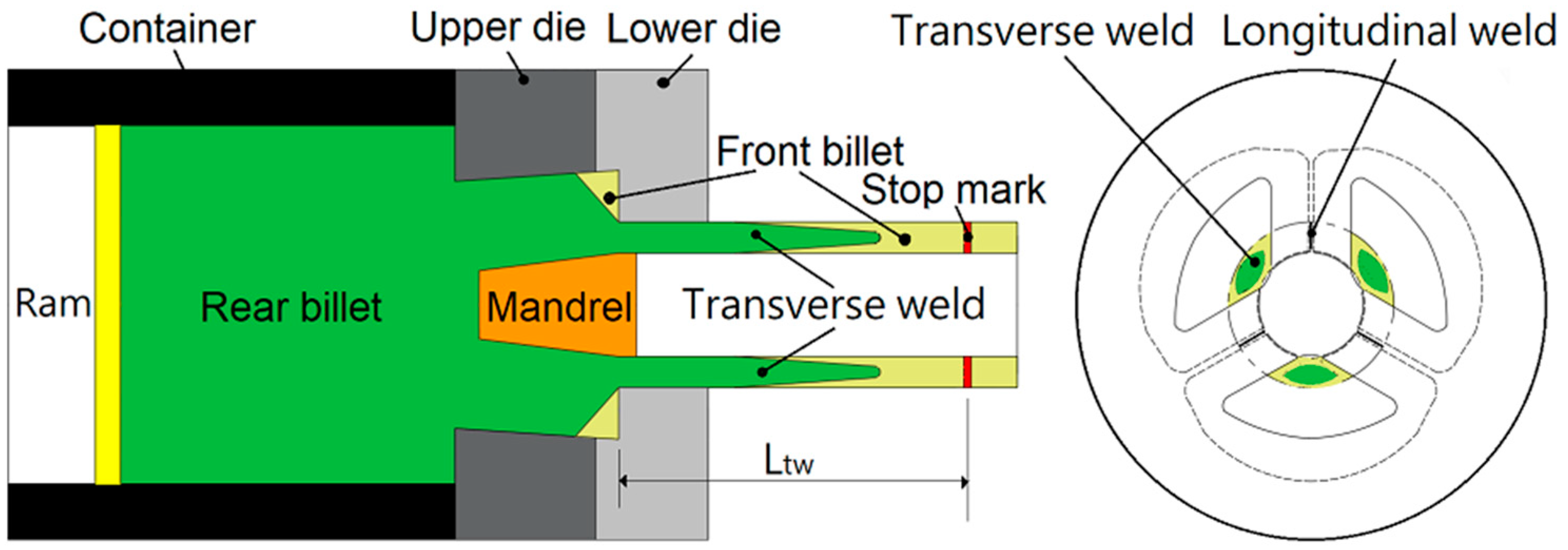
2.1. Definitions of Longitudinal and Transverse Welding Seams

Longitudinal welding seams occur as the billet materials flow separately through the bridge and join together in the welding chamber. The joined interfaces inside the tube product are called longitudinal welding seams. During continuous extrusion, as the front billet is extruded out and the rear billet is input into the container and extruded forward, the interfaces between the front and rear billets are called transverse welding seams. When the extrusion process is suspended to refill a new billet, a circle mark is generated in front of the bearing part, which is called a stop-mark. The transverse seam length, Ltw, is the distance between the stop-mark and joined interface at the front and rear billets. A schematic figure for longitudinal and transverse welding seams and stop-mark is shown in Figure 1.

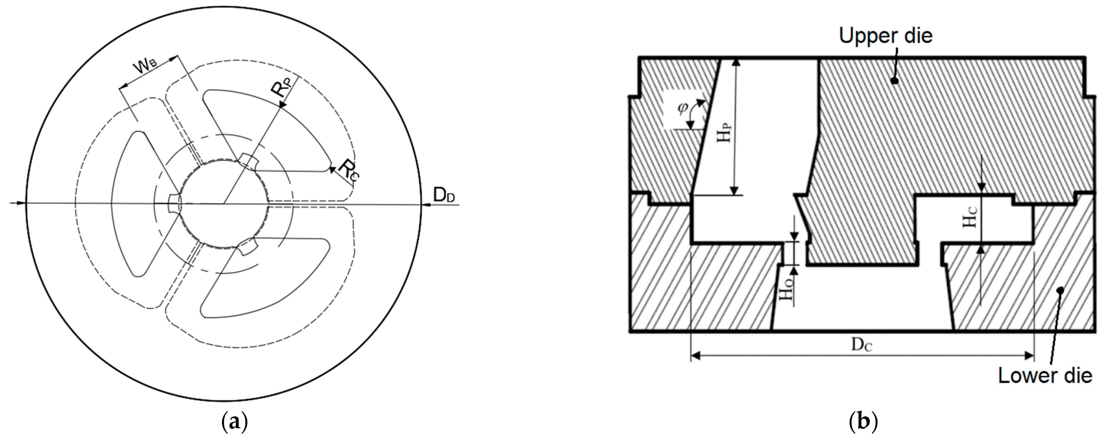
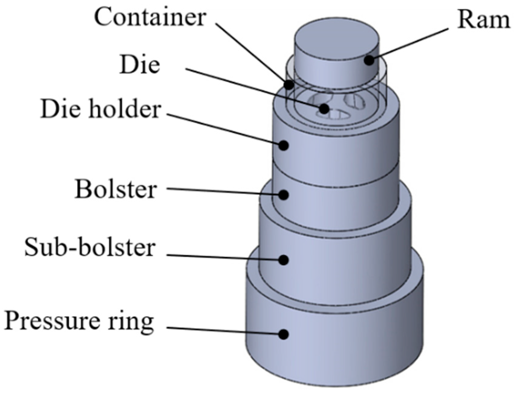
2.2. Configurations of Porthole Dies

The porthole channels and welding chambers of a porthole die used in this study were slightly different from those of a traditional die. The porthole channels of traditional dies are vertically downward to the welding chambers. In this paper, the porthole channel was designed to extend outward from the die entrance to its exit, as shown in Figure 2. In addition, a blocker protruding from the mandrel inside the porthole channel was designed to prevent the billet material flowing directly to the die exit as shown in Figure 2b.
An extrusion die is composed of two parts: (a) a bridge with a mandrel (upper die); and (b) an outer die with a welding camber (lower die), as shown in Figure 3a,b, respectively. Generally, the outer contour of the welding chamber on the bridge part was designed as a circle. In this paper, circular arcs and straight lines were designed for the outer contour on the bridge part. A cylindrical surface was designed on the outer die.
The cross-sectional dimensions of the extruded products were set as 56.2 mm and 80 mm in the inner and outer diameters, respectively. The geometric parameters or variables at the bridge part are shown in Figure 4a, where DD is the die diameter, RP is the porthole radius, WB is the bridge width, and Rc is the corner radius. The corresponding parameter dimensions are shown in Table 1.
The geometric parameters or variables at the welding chamber of a porthole die are shown in Figure 5, where HI and HO are the inner and outer bearing heights, respectively; HP is the porthole height; HM is the die height; and HC is the welding chamber height. The corresponding parameter dimensions are shown in Table 2.
The objective of this study was to design the die parameters to obtain a higher welding pressure and a shorter transverse seam length. To ensure a successful extrusion process, the stress distributions inside the die and extrusion loads have to be smaller than the yielding stress and machine capacity, respectively.

3. Finite Element Simulations of Hot Extrusion of Aluminum Alloy Tubes

3.1. Finite Element Modelling and Simulation Parameters

An explicit and dynamic finite element code “QForm” was adopted to analyze the plastic flow pattern of the aluminum alloy billet within the porthole die cavity during tube extrusion. During the simulations, it is assumed that the billet is rigid plastic, and the die, the container, as well as the flow guide are all rigid. Auto-mesh division was chosen and finer meshes were set around the exit of the die to avoid element crush or fracture after the tube material flowed out from the die. The Levanov friction mode was adopted at the interfaces between the billet and the die, container, and the ram [5]. The flow stresses of aluminum alloy A6061 from the QForm database at a temperature of 500 °C and under different strain rates are shown in Figure 6.
The dimensions of the extruded tube products were 11.9 mm thick and 80 mm in diameter. The structure of a die set was composed of a ram, a container, a die, a die holder, a bolster, a sub-bolster, and a pressure ring, as shown in Figure 7. The front three parts were used to deform the billet material and obtain a desired product geometry. The rear four parts were used to support the die holder and make the die holder fix easily in the extrusion machine. The inner diameter of the container was 183.5 mm. The dimensions of the billets were 177.8 mm in diameter and 740 mm long. They were cut off by a hot cutting machine. The diameter of the ram was slightly smaller than the inner diameter of the container. The dimensions of the die were 238 mm in diameter and 140 mm high. Although the die holder, bolster, sub-bolster, and pressure ring do not influence the material flow of the billet, they were still set up in the finite element simulations. The dimensions of the bolster are 300 and 96 mm in the outer and inner diameters, respectively, and 120 mm in height. The sub-bolster had an outer diameter of 350 mm, an internal geometry of 210 mm, and a width of 120 mm. There was a rectangular hole inside the sub-bolster which was 210 mm in length and 120 mm in width. The pressure ring was placed in the extruder, and the dimensions were determined by the capacity of the extruder. An extruder of 2100 tons was used in the FE simulations and experiments of aluminum alloy tube extrusion. The material parameters and forming parameters used in the FE simulations are shown in Table 3 and Table 4, respectively.
Figure 8a,b show the flow patterns of the new and old materials on the cross-sections of the extrude at positions of 320 mm and 650 mm, respectively, from the stop-mark. As a three-porthole die was used, a three-hold flow pattern of new material appeared inside the old material. Clearly, the area ratio of the new material on the cross-section at a position of 650 mm away from the stop-mark is larger than that at a position of 320 mm away from the stop-mark. The dimensions of the extruded tube products were 11.9 mm thick and 80 mm in diameter.

3.2. Control Factors and Levels in Die Parameters

The dimensions of the die were kept as 238 mm in outer diameter and 140 mm in height. The parameters on the porthole and bridge parts were porthole radius (RP), bridge width (WB), and porthole corner radius (Rc), as shown in Figure 4a. The longitudinal section view of the whole die is shown in Figure 4b. The parameters in the whole die were the porthole height (HP), welding chamber height (HC), outer bearing height (HO), welding chamber diameter (DC), and porthole channel inclination angle (φ). Only the parameters that influence material flow and welding behavior significantly were selected as the control factors and are discussed below. The selected control factors and levels are shown in Table 5.

3.3. Simulation Results and Objective Function

The simulation results of the average welding pressure (PLW) and transverse welding seam length (LTW) for Taguchi cases are shown in Table 6. The responses of each factor on the average welding pressure and transverse welding seam length are shown in Figure 9 and Figure 10, respectively. For the welding pressure, the larger the better case. A higher welding pressure can be obtained with a higher value of every factor. For transverse welding seam length, the smaller the better case. A shorter length can be obtained with a smaller welding chamber height and porthole radius and with a larger bridge width and outer bearing length. The bridge width and outer bearing length influence the transverse welding seam length slightly. The responses of welding chamber height and porthole radius to the welding pressure and transverse welding seam length are contradictory, which means as these factors increase, both the welding pressure and transverse welding seam length increase simultaneously. The objective of this study was to make the welding pressure of the product over a required value and reduce the transverse welding seam length as much as possible. Therefore, a compromising objective function has to be proposed to consider the responses to the welding pressure and transverse welding seam length simultaneously. If only the maximum welding pressure is considered, the optimized levels for each factor are 77.5 mm for the porthole radius, 37 mm for the bridge width, 45 mm for the welding chamber height, and 11 mm for the outer bearing length. All the simulation results including the original die design are shown in Table 6.
A compromising objective function J was proposed to consider the responses to the welding pressure and transverse welding seam length simultaneously as below:
J = P L W P L W × α 1 L T W L T W × α 2
where PLW and PLW are the welding pressures with the modified die design and the original die design, respectively. LTW and LTW are the transverse weld lengths with the modified die and the original die, respectively. α1 and α2 (=0~1) are weighting coefficients for welding pressure and transverse seam length, respectively. As the response on the transverse seam length is the smaller the better, a minus sign is attached on the term of the transverse seam length.
There are two simulation results in the formulation of J. One is the welding pressure at the longitudinal weld seam and the other is the length of the transverse weld seam. The welding pressure at the longitudinal weld seam is the larger the better, whereas the longitudinal weld seam length is the smaller the better, therefore, there is a minus sign in front of the term of LTW/LTW. The extent of importance for these two factors is dependent on the ratio of weighting coefficients, α1/α2.
Several different weighting coefficients are set, and the corresponding objective function values J are shown in Table 7. For the largest welding pressure case PMax, the corresponding transverse seam length, LTW, is larger than the original case by about 400 mm. The J value for case PMax is not a maximal value among all the cases. The maximum J value occurred at case 8. The J value becomes larger for a larger weighting coefficient α1. If the welding pressure is more important than the transverse seam length, α1 should be larger and α2 should be smaller. Clearly, case 8 with A3B2C1D3 is the best combination from the Taguchi analysis.

3.4. Discussion

With the modified die design, the effects of various die design factors on the welding pressure and transverse welding seam length obtained by finite element simulations are summarized in Table 6. For a good design factor combination, a sound product with a large welding pressure at the longitudinal welding seam and a small transverse welding seam length is desired in a continuous extrusion process with a porthole die design. Sometimes these two objectives are conflicting, which means it is difficult to obtain a maximal welding pressure and a minimal transverse welding seam length simultaneously using a die factor combination. Therefore, sometimes trade-offs have to be made. For example, if welding pressure is more important, as long as the welding pressure value reaches a certain required level, the transverse welding seam length could act as a sacrifice. In this paper, an objective function with double weighting coefficients combined with the Taguchi method was proposed to determine the extent of importance between the welding pressure and transverse welding seam length. From Table 6, it is known that the maximal welding pressure occurred in the case with a combination of A3B3C3D3, whereas the minimal transverse welding seam length occurred in the case with a combination of A1B1C1D2. The extent of importance for welding pressure and transverse welding seam length is dependent on the weighting coefficient ratio, α12, as shown in Table 7. α12 = 0.5 denotes equal importance between the welding pressure and transverse welding seam length. From Table 7, it is known that the maximal objective function J value occurred in case 8 for all the α12 ratios of 0.5/0.5, 0.6/0.4, 0.7/0.3, and 0.8/0.2, which means if welding pressure is more important, then the combination of case 8 is an appropriate die geometry and dimension for obtaining a sound product with better mechanical properties at the longitudinal welds.

4. Experiments of Hot Extrusion of Aluminum Alloy Tubes

The extrusion experiments of aluminum alloy A6061 tubes were conducted using a 2100-ton extrusion machine. The experimental extrusion conditions are the same as those in the finite element simulations and are shown in Table 3 and Table 4. The compositions of the aluminum alloy A6061 used in the tube extrusion experiments are given in Table 8.

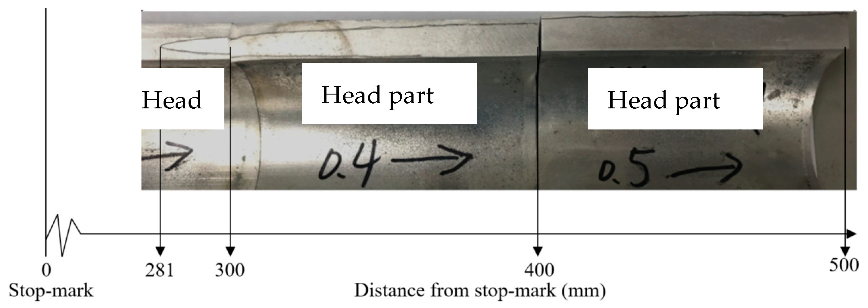
4.1. Measurements of Transverse Seam Length

Corrosion tests are usually used for observations of longitudinal or transverse welding seams. A solution of sodium hydroxide (NaOH) with a concentration of 1:10 to water was used to corrode aluminum alloy at longitudinal and transverse sections of extruded tubes at room temperature for a period of 50 min. Corrosion tests were conducted to observe the interface of the transverse welding seam. The boundaries at the transverse welding seam on a longitudinal section of the extruded tube is shown in Figure 11, from which the starting and ending points of the transverse seam length can be observed. The boundaries at the transverse welding seam on a cross-section of the extruded tube is shown in Figure 12, from which the cross-sectional area ratio of the new material to the old material can be calculated.
The comparisons of cross-sectional area ratios using original and modified die designs are shown in Figure 13. The numerical and experimental new material area percentages at different positions from the stop-mark between the original and modified die designs are shown in the figure. From the figure, it is known that the new material area percentage at the position of about 250 mm from the stop-mark increases dramatically and gradually reaches 100% at about 700 mm from the stop-mark. Clearly, a slightly shorter transverse welding seam length is obtained using the modified die design. The tendency of the simulation results is the same as that of the experimental values.

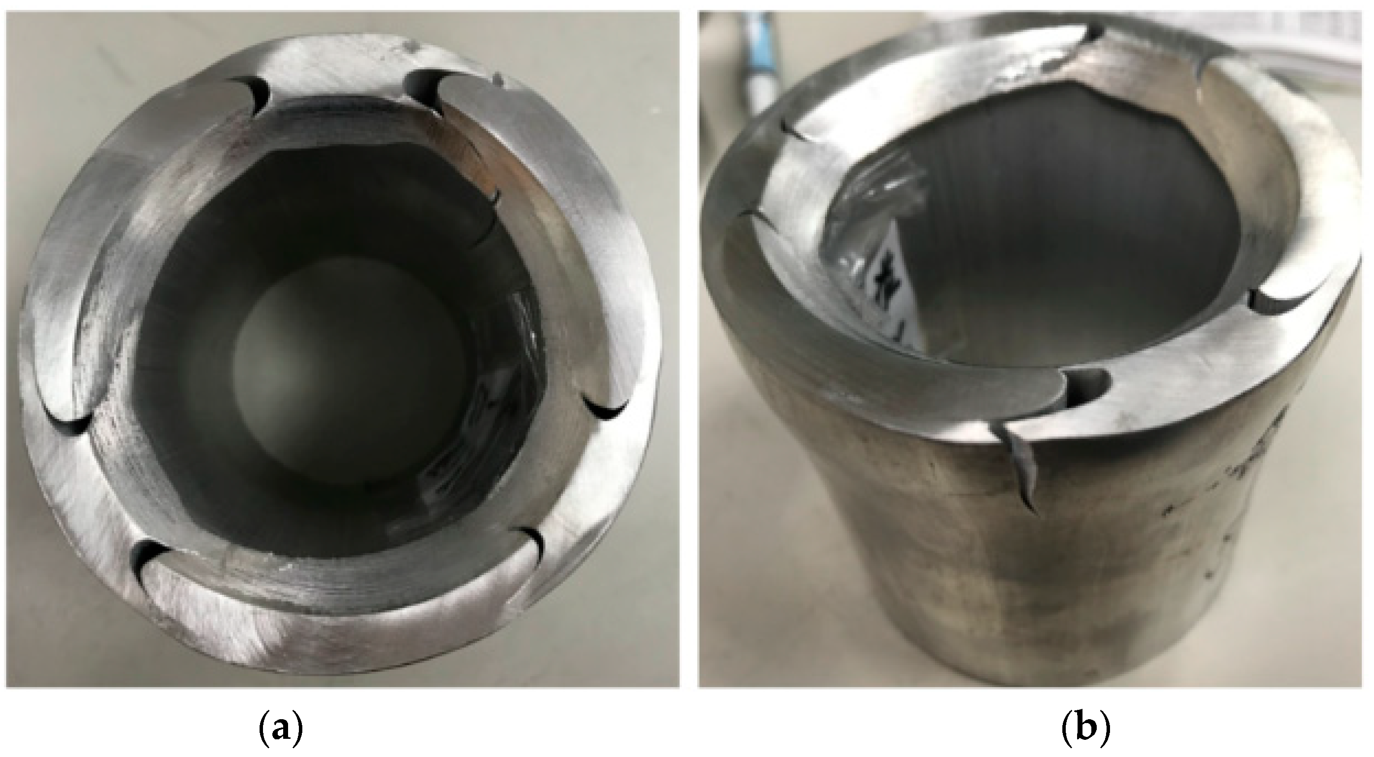
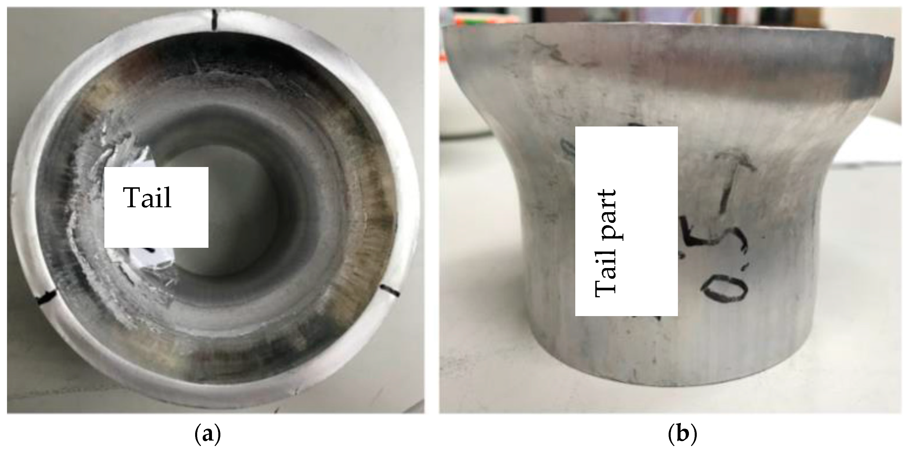
4.2. Tube Expansion Tests

The extrusion experiments were conducted with the modified die and optimized forming conditions. The welding strength of the extruded tube at the longitudinal welding seams were determined by expansion tests. The expansion test results of the tube section at the position within the transverse welding zone are shown in Figure 14 and Figure 15, whereas those out of the transverse welding zone are shown in Figure 16 and Figure 17. A cone-shaped die was designed and a universal testing machine was used to conduct tube expansion tests. Tube sections that 100 mm long were taken from the extruded tubes and were used as the specimens. The loading curve during the expansion tests was recorded. After the expansion tests, the appearance of a tube section taken with a distance of 300 mm from the stop-mark is shown in Figure 14. Clearly, the new and old materials on the cross-section have not bonded completely. The loading curve during the expansion test is shown in Figure 15.
Figure 16 and Figure 17 show the appearance of the tested tube and the loading curve during the expansion test, respectively, for tube section at a position of 500 mm in front of the stop-mark. The expansion tests were used to understand the welding strength at the longitudinal welding seams. Clearly, fracture occurs at the tube itself not at the longitudinal welding seams, which means the welded materials have bonded completely and the bonding strength at the longitudinal welding seams is stronger than the tube itself. The loading curve during the expansion test is shown in Figure 16. Clearly, two anaclastic points were observed. The expansion tests were not completed, and the maximum load for the fracture point was much higher than 500 kN.
From the expansion tests, it is known that there are two kinds of loading curves during the expansion tests. The strength of the tube product with a curve of two anaclastic points is higher than that with a monotonic curve. The tube sections behind the stop-mark are weaker than those far in front of the stop-mark, because the tube sections in front of the stop-mark are the joining sections of new and old materials. The tube sections 500 mm ahead from the stop-mark show a curve of two anaclastic points and have a stronger strength.
The simulated mean welding pressure using the case of Pmax is 88.6 MPa, as shown in Table 6. The present authors have derived a formula for calculating the mean welding pressure. From the expansion test results of pushing force, the experimental mean welding pressure could be obtained as 89.1 MPa. The comparison between these two values could validate the simulation results of welding pressures.

5. Conclusions

The finite element software QForm was used to analyze the flow pattern of billets during hot extrusion of aluminum alloy A6061 tubes. The effects of the die geometries such as welding chamber height, porthole radius, bridge width, bearing length, etc., on the welding pressure and transverse seam length were discussed. The simulation results showed higher welding pressures were obtained as all the geometric factors increased. For the effects on the transverse seam length, larger bridge widths and outer bearing lengths, and smaller porthole radii and welding chamber heights decreased the transverse weld seam length. Porthole radii and welding chamber heights had different effects on the welding pressure and transverse seam length. An objective equation J was proposed to evaluate the effects of the welding pressure and transverse seam length simultaneously. The maximal value J was obtained with the forming conditions of 37 mm in bridge width, 72.5 mm in porthole radius, 25 mm in welding chamber height, and 11 mm in outer bearing length. The transverse welding seam length with the revised die design was 1300 mm, which is 300 mm shorter than that with the original die design.

Author Contributions

Conceptualization, Y.-M.H.; formal analysis, I.-P.H.; writing—review and editing, Y.-M.H.; Figure drawing, I.-P.H. All authors have read and agreed to the published version of the manuscript.

Funding

This research was funded by National Science and Technology Council of the Republic of China under Grant no. MOST 106-2622-E-110-006-CC3.

Data Availability Statement

Not applicable.

Acknowledgments

The authors would like to extend their thanks to the National Science and Technology Council of the Republic of China under Grant no. MOST 106-2622-E-110-006 -CC3. The advice and financial support of NSTC are greatly acknowledged.

Conflicts of Interest

The authors declare no conflict of interest.

References

  1. Groover, M.P. Fundamentals of Modern Manufacturing, Materials, Processes, and Systems, 4th ed.; John Wiley & Sons, Inc.: Hoboken, NJ, USA, 2014; pp. 421–422. [Google Scholar]
  2. Wang, L.; Zhou, J.; Duszczyk, J.; Katgerman, L. Friction in aluminum extrusion—Part 1: A review of friction testing techniques for aluminum extrusion. Tribol. Int. 2012, 56, 89–98. [Google Scholar] [CrossRef]
  3. Wang, L.; Yang, H. Friction in aluminum extrusion—Part 2: A review of friction models for aluminum extrusion. Tribol. Int. 2012, 56, 99–106. [Google Scholar] [CrossRef]
  4. Marín, M.M.; Camacho, A.M.; Pérez, J.A. Influence of the temperature on AA6061 aluminum alloy in a hot extrusion process. Procedia Manuf. 2017, 13, 327–334. [Google Scholar] [CrossRef]
  5. Bandini, C.; Reggiani, B.; Donati, L.; Tomesani, L. Code Validation and Development of User Routines for Microstructural Prediction with Qform. Mater. Today Proc. 2015, 2, 4904–4914. [Google Scholar] [CrossRef]
  6. Chen, F.K.; Chuang, W.C.; Torng, S. Finite element analysis of multi-hole extrusion of aluminum-alloy tubes. J. Mater. Process. Technol. 2008, 201, 150–155. [Google Scholar] [CrossRef]
  7. Liu, G.; Zhou, J.; Duszczyk, J. Finite Element Simulation of Magnesium Extrusion to Manufacture a Cross-Shaped Profile. J. Manuf. Sci. Eng. 2007, 129, 607–614. [Google Scholar] [CrossRef]
  8. Liu, G.; Zhou, J.; Duszczyk, J. Process optimization diagram based on FEM simulation for extrusion of AZ31 profile. Trans. Nonferrous Met. Soc. China 2008, 18, 247–251. [Google Scholar] [CrossRef]
  9. Sikand, R.; Kumar, A.M.; Sachdev, A.K.; Luo, A.A.; Jain, V.; Gupta, A.K. AM30 porthole die extrusions—A comparison with circular seamless extruded tubes. J. Mater. Process. Technol. 2009, 209, 6010–6020. [Google Scholar] [CrossRef]
  10. Li, Q.; Harris, C.; Jolly, M.R. Finite element modelling simulation of transverse welding phenomenon in aluminum extrusion process. Mater. Des. 2003, 24, 493–496. [Google Scholar] [CrossRef]
  11. Mahmoodkhani, Y.; Wells, M.; Parson, N.; Jowett, C.; Poole, W. Modeling the formation of transverse weld during billet-on-billet extrusion. Materials 2014, 7, 3470–3480. [Google Scholar] [CrossRef]
  12. Zhang, C.; Dong, Y.; Zhao, G.; Chen, L. Experimental and numerical investigation on transverse weld of hollow aluminum profile during porthole extrusion process. Procedia Eng. 2017, 207, 1653–1658. [Google Scholar] [CrossRef]
  13. den Bakker, A.J.; Katgerman, L.; van der Zwaag, S. Analysis of the structure and resulting mechanical properties of aluminium extrusions containing a charge weld interface. J. Mater. Process. Technol. 2016, 229, 9–21. [Google Scholar] [CrossRef]
  14. Zhang, C.; Dong, Y.; Wang, C.; Zhao, G.; Chen, L.; Sun, W. Evolution of transverse weld during porthole extrusion of AA7N01 hollow profile. J. Mater. Process. Technol. 2017, 248, 103–114. [Google Scholar] [CrossRef]
  15. den Bakker, A.J.; Werkhoven, R.J.; Sillekens, W.H.; Katgerman, L. The origin of weld seam defects related to metal flow in the hot extrusion of aluminium alloys EN AW-6060 and EN AW-6082. J. Mater. Process. Technol. 2014, 214, 2349–2358. [Google Scholar] [CrossRef]
  16. Kim, K.J.; Lee, C.H.; Yang, D.Y. Investigation into the improvement of welding strength in three-dimensional extrusion of tubes using porthole dies. J. Mater. Process. Technol. 2002, 130–131, 426–431. [Google Scholar] [CrossRef]
  17. Zhao, Y.; Song, B.; Yan, Z.; Zhang, X.; Pei, J. Microstructure and mechanical properties of extrusion welds in continuous extrusion of AA6063 aluminium alloy with double billets. J. Mater. Process. Technol. 2016, 235, 149–157. [Google Scholar] [CrossRef]
  18. Donati, L.; Tomesani, L. The effect of die design on the production and seam weld quality of extruded aluminum profiles. J. Mater. Process. Technol. 2005, 164–165, 1025–1031. [Google Scholar] [CrossRef]
  19. Jo, H.H.; Jeong, C.S.; Lee, S.K.; Kim, B.M. Determination of welding pressure in the non-steady-state porthole die extrusion of improved Al7003 hollow section tubes. J. Mater. Process. Technol. 2003, 139, 428–433. [Google Scholar] [CrossRef]
  20. Choi, M.K.; Park, C.G.; Choi, Y.; Won, T.Y. Aluminum tube extrusion with the porthole die for deconcentrated welding lines. J. Mech. Sci. Technol. 2018, 32, 2245–2251. [Google Scholar] [CrossRef]
  21. Liu, Z.; Li, L.; Yi, J.; Li, S.; Wang, G. Influence of extrusion speed on the seam weld quality in the porthole die extrusion of AZ31 magnesium alloy tube. Int. J. Adv. Manuf. Technol. 2017, 92, 1039–1052. [Google Scholar] [CrossRef]
  22. Lin, G.Y.; Xiao, M.Q.; Feng, D.; Liu, X.Y.; Wang, H.Y.; Zhang, R. Microstructural and mechanical properties of ZA10 alloy tubes and their weld seams prepared by Conform continuous extrusion. Rare Met. 2020, 39, 707–715. [Google Scholar] [CrossRef]
Figure 1. Schematic for transverse and longitudinal welding seams.
Metals 13 00911 g001
Figure 2. Geometric configurations of porthole channels of porthole dies. (a) Traditional die and (b) modified die.
Metals 13 00911 g002
Figure 3. Components of porthole dies. (a) Bridge and mandrel part, and (b) the outer die part.
Metals 13 00911 g003
Figure 4. Geometric parameters in the whole die; (a) top view and (b) longitudinal section view.
Metals 13 00911 g004
Figure 5. Geometric parameters at the welding chamber of the porthole dies.
Metals 13 00911 g005
Figure 6. Flow stresses of aluminum alloys used in finite element simulations.
Metals 13 00911 g006
Figure 7. Components of complete die set.
Metals 13 00911 g007
Figure 8. Flow patterns of new material at different cross-sections from the stop-mark. (a) X = 320 mm, (b) X = 650 mm.
Metals 13 00911 g008
Figure 9. Responses of each factor on the welding pressure.
Metals 13 00911 g009
Figure 10. Responses of each factor on the transverse welding seam length.
Metals 13 00911 g010
Figure 11. Boundaries at transverse welding seams on a longitudinal section of an extruded tube.
Metals 13 00911 g011
Figure 12. Boundaries at a transverse welding seam on the cross-section of an extruded tube.
Metals 13 00911 g012
Figure 13. Comparisons of cross-sectional area ratios using original and modified die designs.
Metals 13 00911 g013
Figure 14. Appearances of a tube section after expansion tests. (a) Top view, and (b) perspective view.
Metals 13 00911 g014
Figure 15. Loading curve during the expansion test for a tube section with a 300 mm distance from the stop-mark.
Metals 13 00911 g015
Figure 16. Appearances for a tube section taken at a position of 500 mm in front of the stop-mark. (a) Top view, and (b) side view.
Metals 13 00911 g016
Figure 17. Loading curve during an expansion test for a tube section with a 500 mm distance from the stop-mark.
Metals 13 00911 g017
Table 1. Dimensions of geometric parameters at the bridge part.
Die diameter, DD [mm]238
Porthole radius, RP [mm]67.5
Bridge width, WB [mm]31
Corner radius, Rc [mm]12
Table 2. Dimensions of the geometric parameters at the welding chamber.
Inner bearing height HI [mm]7.5
Outer bearing height HO [mm]7
Porthole height HP [mm]65
Die height HD [mm]140
Welding chamber height HC [mm]25
Table 3. Material parameters used in FE simulations.
MaterialAl 6061
Extrusion typeDirect extrusion (die is filled)
Ram speed4.1 mm/s
Billet temperature510 °C
Billet length740 mm
Billet diameter177.8 mm
Table 4. Forming conditions used in FE Simulations.
Die materialAISI H-13
Die temperature480 °C
Bolster, Sub-bolster temperature25 °C
Ram temperature420 °C
Container temperature420 °C
Friction modelDefault
(Revanov friction)
Extrusion ratio9.7
Table 5. Control factors and levels used in the Taguchi method.
FactorsLevels
123
ABridge width WB (mm)313437
BPorthole radius Rp (mm)67.572.577.5
CWelding chamber height Hc (mm)253545
DOuter bearing height Ho (mm)3711
Table 6. Simulation results by the Taguchi method.
L9ABCDAverage Welding Pressure
PLW (MPa)
Transverse Welding Seam Length
LTW (mm)
1111163.6739
2122276.8882
3133388.01133
4212374.1750
5223174.71043
6231278.7857
7313274.9808
8321380.4730
9332178.81064
PMax333388.61082
Original111272.0664
Table 7. Objective function values with variable weighting coefficients.
JPLW
(MPa)
LTW
(mm)
α1/α2
Case 0.5/0.50.6/0.40.7/0.30.8/0.2
163.6739−0.110.080.280.48
276.8882−0.130.110.350.59
388.01133−0.240.050.340.64
474.1750−0.050.170.380.60
574.71043−0.27−0.010.260.52
678.7857−0.100.140.380.62
774.9808−0.090.140.360.59
880.47300.010.230.450.67
978.81064−0.250.020.290.55
PMax88.61082−0.200.090.370.66
Original72.06640.000.200.400.60
Table 8. Compositions of the aluminum alloy A6061.
IngredientsSiMgCuZnFeCrMnTiOtherAl
Composition (wt%)0.5–0.80.7–1.20.15–0.40.250.70.02–0.350.150.150.15Bal
Disclaimer/Publisher’s Note: The statements, opinions and data contained in all publications are solely those of the individual author(s) and contributor(s) and not of MDPI and/or the editor(s). MDPI and/or the editor(s) disclaim responsibility for any injury to people or property resulting from any ideas, methods, instructions or products referred to in the content.

