
Green Approach for Electropolishing Surface Treatments of Additive Manufactured Parts: A Comprehensive Review

Abstract
:1. Introduction
2. Electropolishing Treatment
3. Conventional Electropolishing as Post-Processing Treatment
3.1. Titanium-Based Additive Manufacturing Parts
3.2. Steel-Based Additive Manufacturing Parts
3.3. Nickel-Based Additive Manufacturing Parts
3.4. Aluminium Alloy-Based and CoCr Alloy Additive Manufacturing Parts
4. Green Acid-Free Electrolytes
5. State of Art of Green Electropolishing Treatment of Additive Manufacturing Parts
5.1. Titanium Alloy
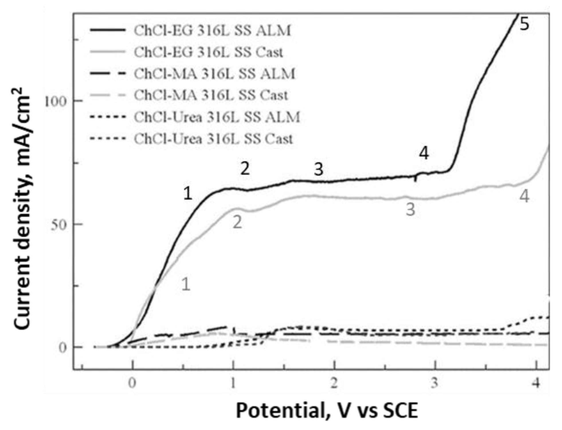
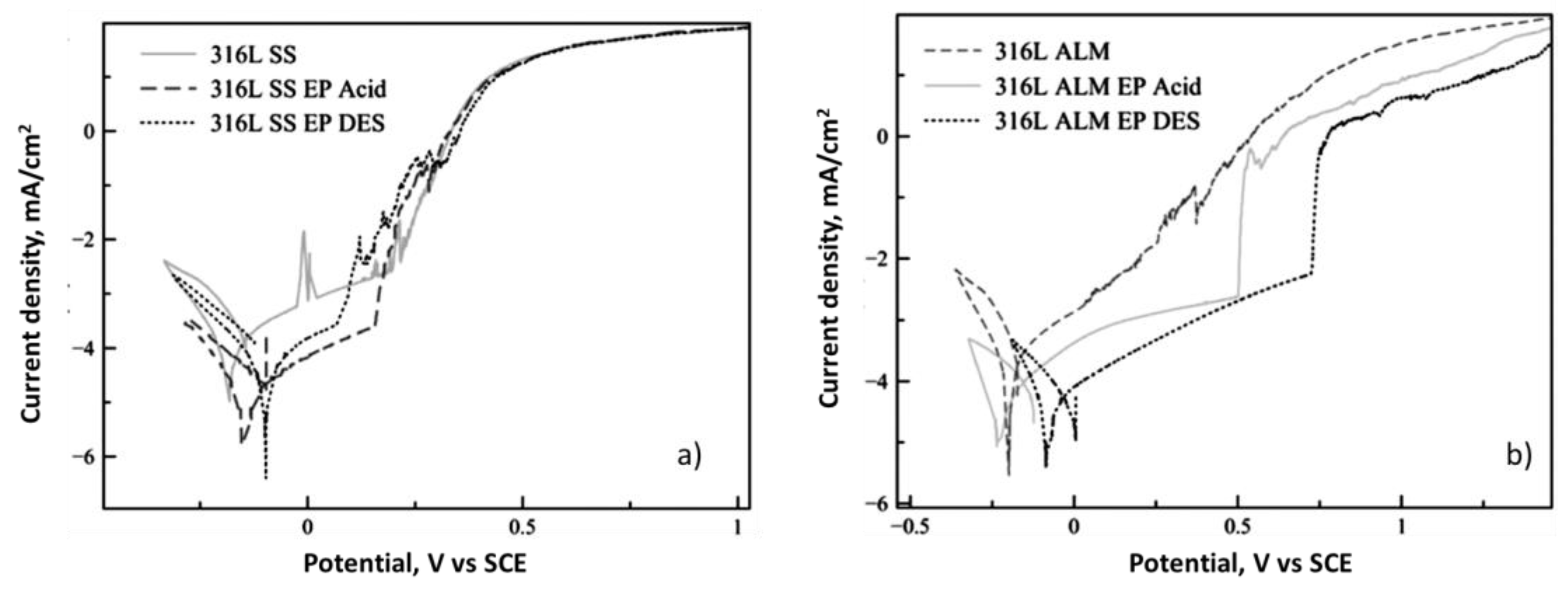
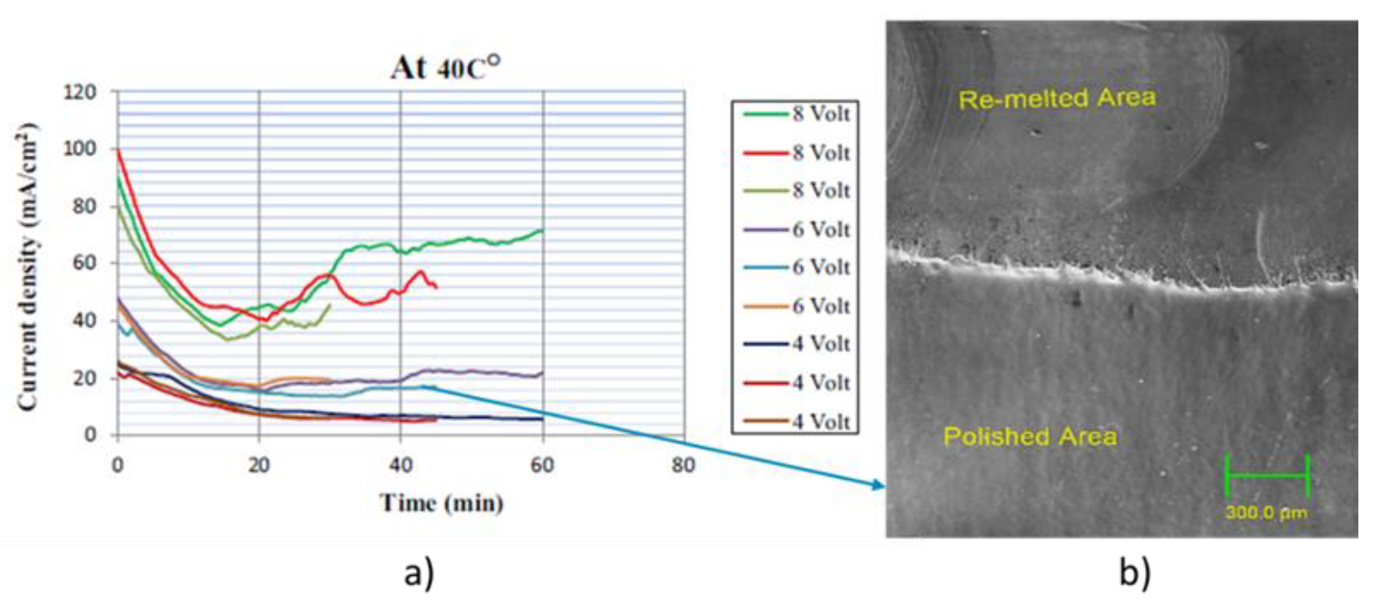
5.2. Stainless Steel
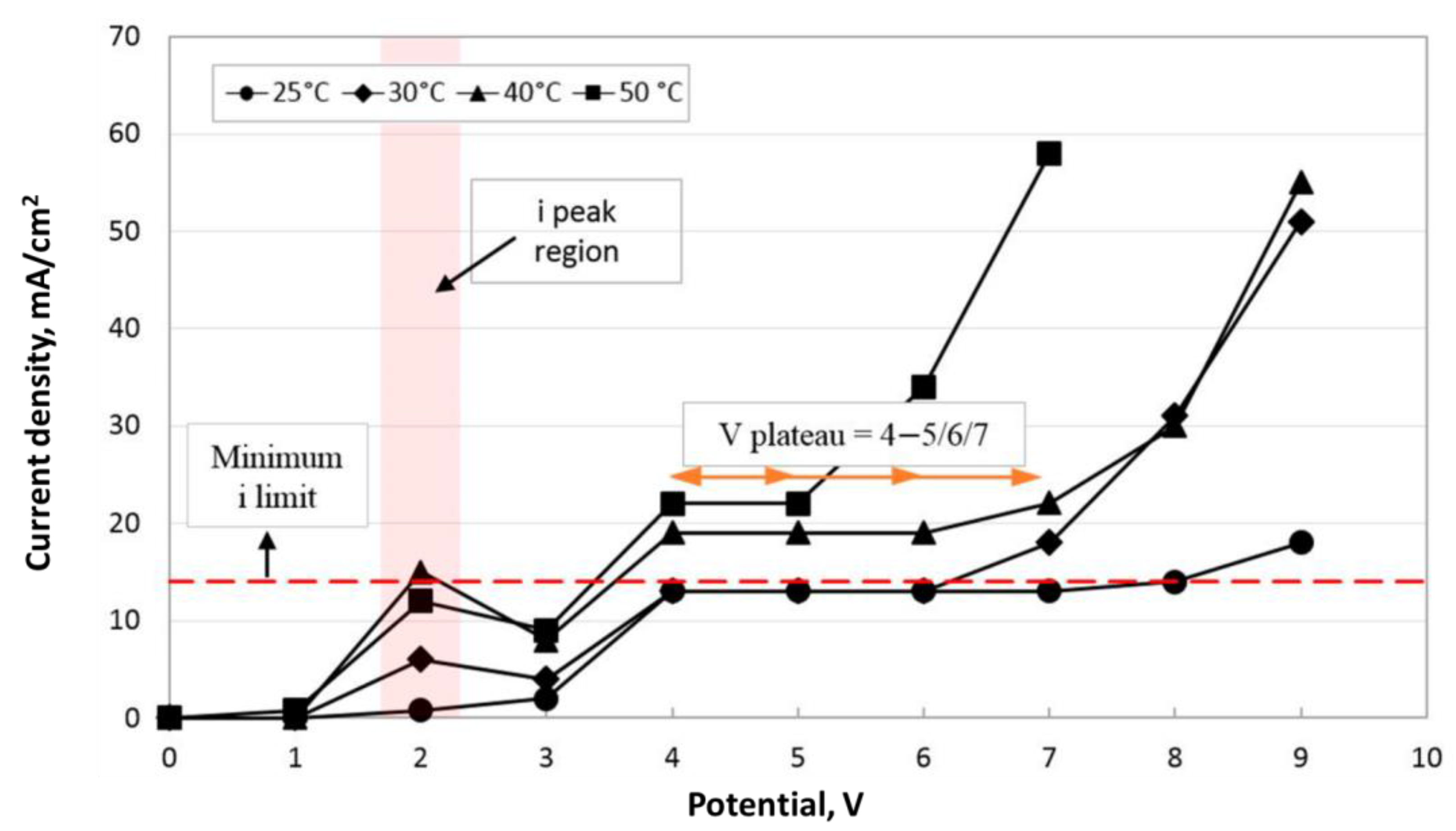
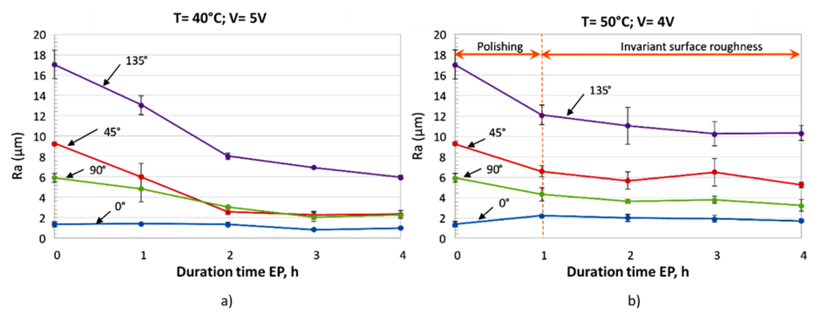
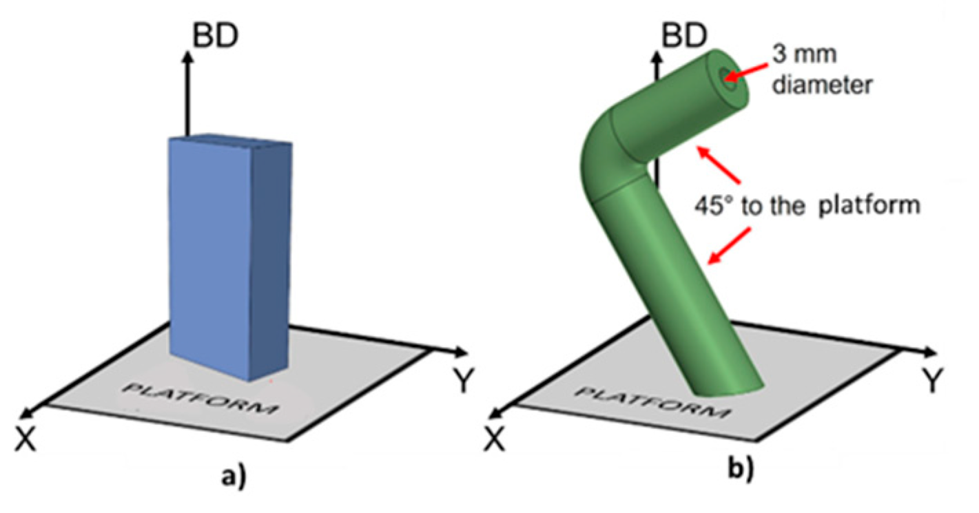
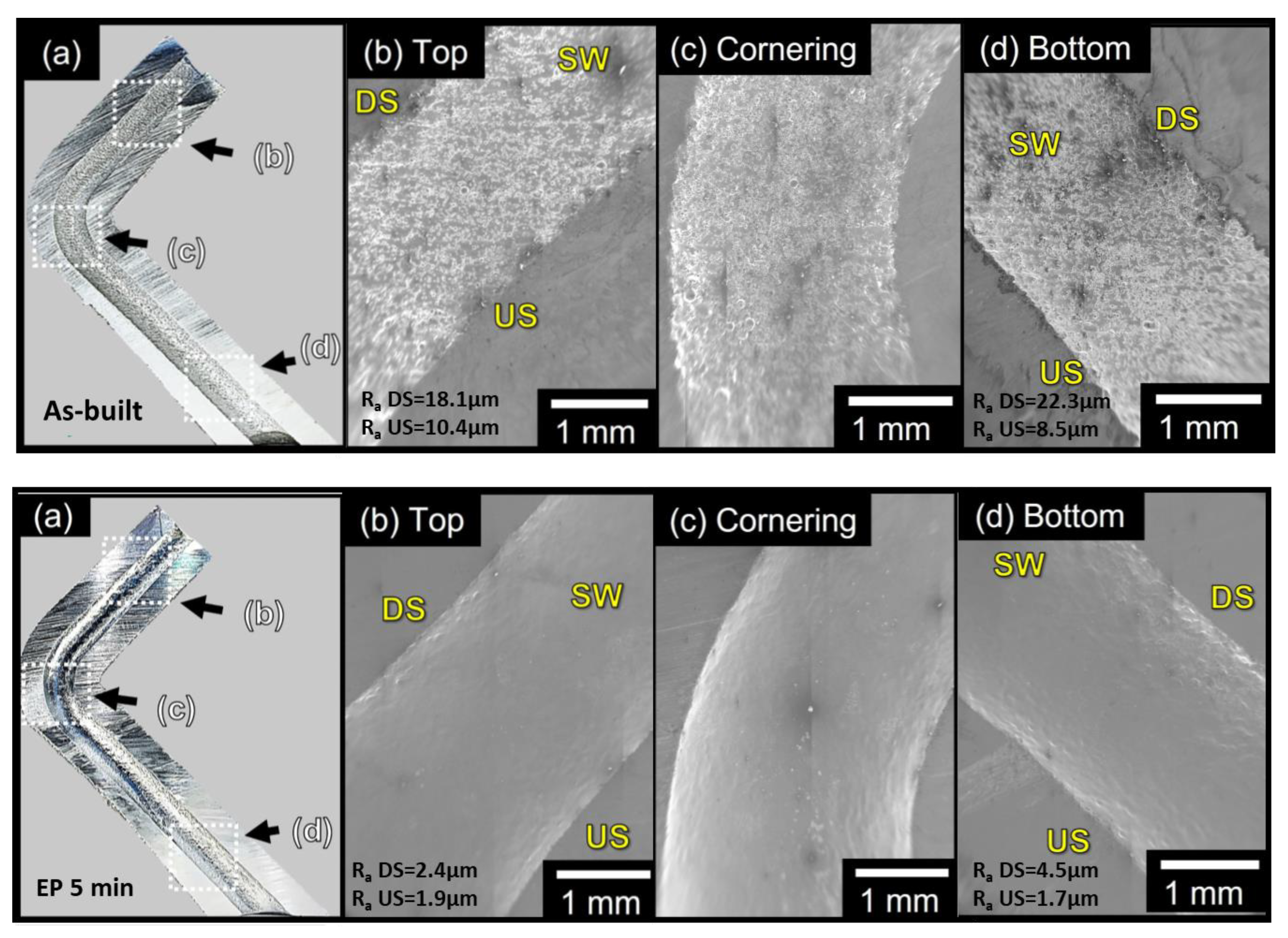
5.3. Ni-Based Alloy
6. Conclusions
7. Future Scope and Development
- The optimisation of the EP treatment parameters to reduce the energy consumption.
- The possibility of investigating the effectiveness of the EP treatment in NaDES-based electrolytes.
- The investigation of the EP treatment using green electrolytes on other kind of alloys, such as the most used aluminium alloy, AlSi10Mg.
- The possibility of reusing the exhaust electrolytic solution.
- The possibility of developing new and renewable DESs solutions.
- The AI and machine learning approaches, as applied to the optimisation process of AM technologies, could help to also optimise the post-processing treatment.
Author Contributions
Funding
Institutional Review Board Statement
Data Availability Statement
Conflicts of Interest
References
- Dilberoglu, U.M.; Gharehpapagh, B.; Yaman, U.; Dolen, M. The Role of Additive Manufacturing in the Era of Industry 4.0. Procedia Manuf. 2017, 11, 545–554. [Google Scholar] [CrossRef]
- Grad, M.; Nadammal, N.; Schultheiss, U.; Lulla, P.; Noster, U. An Integrative Experimental Approach to Design Optimization and Removal Strategies of Supporting Structures Used during L-PBF of SS316L Aortic Stents. Appl. Sci. 2021, 11, 9176. [Google Scholar] [CrossRef]
- Cooke, S.; Ahmadi, K.; Willerth, S.; Herring, R. Metal additive manufacturing: Technology, metallurgy and modelling. J. Manuf. Process. 2020, 57, 978–1003. [Google Scholar] [CrossRef]
- Herzog, D.; Seyda, V.; Wycisk, E.; Emmelmann, C. Additive manufacturing of metals. Acta Mater. 2016, 117, 371–392. [Google Scholar] [CrossRef]
- Hufenbach, J.; Sander, J.; Kochta, F.; Pilz, S.; Voss, A.; Kühn, U.; Gebert, A. Effect of Selective Laser Melting on Microstructure, Mechanical, and Corrosion Properties of Biodegradable FeMnCS for Implant Applications. Adv. Eng. Mater. 2020, 22, 2000182. [Google Scholar] [CrossRef]
- Acquesta, A.; Monetta, T. As-Built EBM and DMLS Ti-6Al-4V Parts: Topography–Corrosion Resistance Relationship in a Simulated Body Fluid. Metals 2020, 10, 1015. [Google Scholar] [CrossRef]
- Kim, U.S.; Park, J.W. High-Quality Surface Finishing of Industrial Three-Dimensional Metal Additive Manufacturing Using Electrochemical Polishing. Int. J. Precis. Eng. Manuf. Technol. 2019, 6, 11–21. [Google Scholar] [CrossRef]
- Acquesta, A.; Monetta, T. The Electropolishing of Additively Manufactured Parts in Titanium: State of the Art. Adv. Eng. Mater. 2021, 23, 2100545. [Google Scholar] [CrossRef]
- Kim, F.H.; Moylan, S.P. Literature Review of Metal Additive Manufacturing Defects; NIST Advanced Manufacturing Series 100-16; US Department of Commerce, National Institute of Standards and Technology: Gaithersburg, MD, USA, 2018. [Google Scholar] [CrossRef]
- Santecchia, E.; Spigarelli, S.; Cabibbo, M. Material Reuse in Laser Powder Bed Fusion: Side Effects of the Laser—Metal Powder Interaction. Metals 2020, 10, 341. [Google Scholar] [CrossRef] [Green Version]
- Pal, R.; Basak, A. Linking Powder Properties, Printing Parameters, Post-Processing Methods, and Fatigue Properties in Additive Manufacturing of AlSi10Mg. Alloys 2022, 1, 149–179. [Google Scholar] [CrossRef]
- Denti, L.; Sola, A. On the Effectiveness of Different Surface Finishing Techniques on A357.0 Parts Produced by Laser-Based Powder Bed Fusion: Surface Roughness and Fatigue Strength. Metals 2019, 9, 1284. [Google Scholar] [CrossRef] [Green Version]
- Avanzini, A.; Battini, D.; Gelfi, M.; Girelli, L.; Petrogalli, C.; Pola, A.; Tocci, M. Investigation on fatigue strength of sand-blasted DMLS-AlSi10Mg alloy. Procedia Struct. Integr. 2019, 18, 119–128. [Google Scholar] [CrossRef]
- Walczak, M.; Szala, M. Effect of shot peening on the surface properties, corrosion and wear performance of 17-4PH steel produced by DMLS additive manufacturing. Arch. Civ. Mech. Eng. 2021, 21, 157. [Google Scholar] [CrossRef]
- Subramaniyan, A.K.; Reddy, A.S.; Mathias, S.; Shrivastava, A.; Raghupatruni, P. Influence of post-processing techniques on the microstructure, properties and surface integrity of Al Si Mg alloy processed by laser powder bed fusion technique. Surf. Coat. Technol. 2021, 425, 127679. [Google Scholar] [CrossRef]
- Peng, C.; Fu, Y.; Wei, H.; Li, S.; Wang, X.; Gao, H. Study on Improvement of Surface Roughness and Induced Residual Stress for Additively Manufactured Metal Parts by Abrasive Flow Machining. Procedia CIRP 2018, 71, 386–389. [Google Scholar] [CrossRef]
- Yasa, E.; Deckers, J.; Kruth, J.P. The investigation of the influence of laser re-melting on density, surface quality and microstructure of selective laser melting parts. Rapid Prototyp. J. 2011, 17, 312–327. [Google Scholar] [CrossRef]
- Tyagi, P.; Goulet, T.; Riso, C.; Stephenson, R.; Chuenprateep, N.; Schlitzer, J.; Benton, C.; Garcia-Moreno, F. Reducing the roughness of internal surface of an additive manufacturing produced 316 steel component by chempolishing and electropolishing. Addit. Manuf. 2019, 25, 32–38. [Google Scholar] [CrossRef] [Green Version]
- Charazińska, S.; Lochyński, P.; Markiewicz, M.; Stolte, S.; Burszta-Adamiak, E. Treatment of electropolishing industrial wastewater and its impact on the immobilisation of Daphnia magna. Environ. Res. 2022, 212, 113438. [Google Scholar] [CrossRef] [PubMed]
- Singh, J.; Singh, G.; Pandey, P.M. Electric Discharge Machining Using Rapid Manufactured Complex Shape Copper Electrode with Cryogenic Cooling Channel. Proc. Inst. Mech. Eng. Part B J. Eng. Manuf. 2021, 235, 173–185. [Google Scholar] [CrossRef]
- Smith, E.L.; Abbott, A.P.; Ryder, K.S. Deep Eutectic Solvents (DESs) and Their Applications. Chem. Rev. 2014, 114, 11060–11082. [Google Scholar] [CrossRef] [Green Version]
- Chaghazardi, Z.; Wüthrich, R. Review—Electropolishing of Additive Manufactured Metal Parts. J. Electrochem. Soc. 2022, 169, 043510. [Google Scholar] [CrossRef]
- Basha, M.; Jain, V.; Sankar, M. State of the art on chemical and electrochemical based finishing processes for additive manufactured features. Addit. Manuf. 2022, 58, 103028. [Google Scholar] [CrossRef]
- Landolt, D. Fundamental aspects of electropolishing. Electrochim. Acta 1987, 32, 1–11. [Google Scholar] [CrossRef]
- Acquesta, A.; Monetta, T. Electropolishing in Ecofriendly Solution of Ti6Al4V Parts Produced by Electron Beam Melting. Metall. Ital. 2021, 113, 74–80. [Google Scholar]
- Jacquet, P.A. Electrolytic and chemical polishing. Met. Rev. 1956, 1, 157–238. [Google Scholar] [CrossRef]
- Hoar, T.P.; Mowat, J.A.S. Mechanism of Electropolishing. Nature 1950, 165, 64–65. [Google Scholar] [CrossRef]
- Elmore, W.C. Electrolytic Polishing. J. Appl. Phys. 1939, 10, 724–727. [Google Scholar] [CrossRef]
- Datta, M.; Vega, L.; Romankiw, L.; Duby, P. Mass transport effects during electropolishing of iron in phosphoric-sulfuric acid. Electrochim. Acta 1992, 37, 2469–2475. [Google Scholar] [CrossRef]
- Neelakantan, L.; Pareek, A.; Hassel, A.W. Electro-dissolution of 30Nb–Ti alloys in methanolic sulfuric acid—Optimal conditions for electropolishing. Electrochim. Acta 2011, 56, 6678–6682. [Google Scholar] [CrossRef]
- Grimm, R.-D.; Landolt, D. Salt films formed during mass transport controlled dissolution of iron-chromium alloys in concentrated chloride media. Corros. Sci. 1994, 36, 1847–1868. [Google Scholar] [CrossRef]
- Matlosz, M.; Magaino, S.; Landolt, D. Impedance Analysis of a Model Mechanism for Acceptor-Limited Electropolishing. J. Electrochem. Soc. 1994, 141, 410–418. [Google Scholar] [CrossRef]
- Monetta, T.; Acquesta, A.; Bellucci, F. Evaluation of Roughness and Electrochemical Behavior of Titanium in Biological Environment. Metall. Ital. 2014, 106, 13–21. [Google Scholar]
- Townsend, A.; Senin, N.; Blunt, L.; Leach, R.K.; Taylor, J.S. Surface texture metrology for metal additive manufacturing: A review. Precis. Eng. 2016, 46, 34–47. [Google Scholar] [CrossRef] [Green Version]
- Kumar, S.; Kushwaha, A.; Nagesha, B.K.; Barad, S. Hybrid surface characterisation of intra thin-walled Ti6Al4V surfaces produced by laser powder bed fusion technology. Surf. Topogr. Metrol. Prop. 2022, 10, 015006. [Google Scholar] [CrossRef]
- Grimm, T.; Witt, G.; Wiora, G. Characterization of Additive Manufactured Surfaces with Confocal Microscopy. Surf. Topogr. Metrol. Prop. 2014, 3, 139–144. [Google Scholar]
- Zanini, F.; Pagani, L.; Scott, P.; Savio, E.; Carmignato, S. Measurement of Additively Manufactured Surfaces with Re-Entrant Features by X-Ray Computed Tomography. In Proceedings of the ASPE/Euspen Conference: Advancing Precision in Additive Manufacturing, Leuven, Belgium, 7–9 February 2017. [Google Scholar]
- Moylan, S. Progress toward Standardized Additive Manufacturing Test Artifacts. In Proceedings of the ASPE 2015 Spring Topical Meeting: Achieving Precision Tolerances in Additive Manufacturing, Raleigh, NC, USA, 26–29 April 2015; pp. 100–105. [Google Scholar]
- Nakar, D.; Harel, D.; Hirsch, B. Electropolishing effect on roughness metrics of ground stainless steel: A length scale study. Surf. Topogr. Metrol. Prop. 2017, 6, 015003. [Google Scholar] [CrossRef]
- Urlea, V.; Brailovski, V. Electropolishing and electropolishing-related allowances for powder bed selectively laser-melted Ti-6Al-4V alloy components. J. Mater. Process. Technol. 2017, 242, 1–11. [Google Scholar] [CrossRef]
- Zhang, Y. Electropolishing Mechanism of Ti-6Al-4V Alloy Fabricated by Selective Laser Melting. Int. J. Electrochem. Sci. 2018, 13, 4792–4807. [Google Scholar] [CrossRef]
- Wu, Y.-C.; Kuo, C.-N.; Chung, Y.-C.; Ng, C.-H.; Huang, J.C. Effects of Electropolishing on Mechanical Properties and Bio-Corrosion of Ti6Al4V Fabricated by Electron Beam Melting Additive Manufacturing. Materials 2019, 12, 1466. [Google Scholar] [CrossRef] [PubMed] [Green Version]
- Pyka, G.; Burakowski, A.; Kerckhofs, G.; Moesen, M.; Van Bael, S.; Schrooten, J.; Wevers, M. Surface Modification of Ti6Al4V Open Porous Structures Produced by Additive Manufacturing. Adv. Eng. Mater. 2012, 14, 363–370. [Google Scholar] [CrossRef]
- Langi, E.; Zhao, L.; Jamshidi, P.; Attallah, M.; Silberschmidt, V.; Willcock, H.; Vogt, F. A comparative study of microstructures and nanomechanical properties of additively manufactured and commercial metallic stents. Mater. Today Commun. 2022, 31, 103372. [Google Scholar] [CrossRef]
- Rotty, C.; Mandroyan, A.; Doche, M.-L.; Hihn, J. Electropolishing of CuZn brasses and 316L stainless steels: Influence of alloy composition or preparation process (ALM vs. standard method). Surf. Coat. Technol. 2016, 307, 125–135. [Google Scholar] [CrossRef]
- Jain, S.; Corliss, M.; Tai, B.; Hung, W.N. Electrochemical polishing of selective laser melted Inconel 718. Procedia Manuf. 2019, 34, 239–246. [Google Scholar] [CrossRef]
- Baicheng, Z.; Xiaohua, L.; Jiaming, B.; Junfeng, G.; Pan, W.; Chen-Nan, S.; Muiling, N.; Guojun, Q.; Jun, W. Study of selective laser melting (SLM) Inconel 718 part surface improvement by electrochemical polishing. Mater. Des. 2017, 116, 531–537. [Google Scholar] [CrossRef]
- Urlea, V.; Brailovski, V. Electropolishing and electropolishing-related allowances for IN625 alloy components fabricated by laser powder-bed fusion. Int. J. Adv. Manuf. Technol. 2017, 92, 4487–4499. [Google Scholar] [CrossRef]
- Liu, H.; Ye, M.; Ye, Z.; Wang, L.; Wang, G.; Shen, X.; Xu, P.; Wang, C. High-quality surface smoothening of laser powder bed fusion additive manufacturing AlSi10Mg via intermittent electrochemical polishing. Surf. Coat. Technol. 2022, 443, 128608. [Google Scholar] [CrossRef]
- Shrivastava, A.; Mathias, S.; Prasad, R.; Kumar, S. Investigation on Electrolytically Polished AlSi10Mg Alloy Processed via Selective Laser Melting/3D Printing Route. Proc. Inst. Mech. Eng. Part L J. Mater. Des. Appl. 2020. [Google Scholar] [CrossRef]
- Demir, A.G.; Previtali, B. Additive manufacturing of cardiovascular CoCr stents by selective laser melting. Mater. Des. 2017, 119, 338–350. [Google Scholar] [CrossRef] [Green Version]
- Abbott, A.P.; Boothby, D.; Capper, G.; Davies, D.L.; Rasheed, R.K. Deep Eutectic Solvents Formed between Choline Chloride and Carboxylic Acids: Versatile Alternatives to Ionic Liquids. J. Am. Chem. Soc. 2004, 126, 9142–9147. [Google Scholar] [CrossRef]
- Hansen, B.B.; Spittle, S.; Chen, B.; Poe, D.; Zhang, Y.; Klein, J.M.; Horton, A.; Adhikari, L.; Zelovich, T.; Doherty, B.W.; et al. Deep Eutectic Solvents: A Review of Fundamentals and Applications. Chem. Rev. 2020, 121, 1232–1285. [Google Scholar] [CrossRef]
- Abbott, A.P.; Capper, G.; Davies, D.L.; Rasheed, R.K.; Tambyrajah, V. Novel solvent properties of choline chloride/urea mixtures. Chem. Commun. 2002, 39, 70–71. [Google Scholar] [CrossRef] [Green Version]
- Bezerra-Neto, J.R.; Sousa, N.G.; dos Santos, L.P.M.; Correia, A.N.; de Lima-Neto, P. The effect of water on the physicochemical properties of an ethylene glycol and choline chloride mixture containing Cu2+ ions: Electrochemical results and dynamic molecular simulation approach. Phys. Chem. Chem. Phys. 2018, 20, 9321–9327. [Google Scholar] [CrossRef] [PubMed]
- Figueiredo, M.; Gomes, C.; Costa, R.; Martins, A.; Pereira, C.M.; Silva, F. Differential capacity of a deep eutectic solvent based on choline chloride and glycerol on solid electrodes. Electrochim. Acta 2009, 54, 2630–2634. [Google Scholar] [CrossRef]
- Choi, Y.H.; van Spronsen, J.; Dai, Y.; Verberne, M.; Hollmann, F.; Arends, I.W.C.E.; Witkamp, G.-J.; Verpoorte, R. Are Natural Deep Eutectic Solvents the Missing Link in Understanding Cellular Metabolism and Physiology? Plant Physiol. 2011, 156, 1701–1705. [Google Scholar] [CrossRef] [Green Version]
- Picchio, M.L.; Minudri, D.; Mantione, D.; Criado-Gonzalez, M.; Guzmán-González, G.; Schmarsow, R.; Müller, A.J.; Tomé, L.C.; Minari, R.J.; Mecerreyes, D. Natural Deep Eutectic Solvents Based on Choline Chloride and Phenolic Compounds as Efficient Bioadhesives and Corrosion Protectors. ACS Sustain. Chem. Eng. 2022, 10, 8135–8142. [Google Scholar] [CrossRef]
- Li, C.; Li, D.; Zou, S.; Li, Z.; Yin, J.; Wang, A.; Cui, Y.; Yao, Z.; Zhao, Q. Extraction desulfurization process of fuels with ammonium-based deep eutectic solvents. Green Chem. 2013, 15, 2793–2799. [Google Scholar] [CrossRef]
- Oliveira, F.S.; Pereiro, A.B.; Rebelo, L.P.N.; Marrucho, I.M. Deep eutectic solvents as extraction media for azeotropic mixtures. Green Chem. 2013, 15, 1326–1330. [Google Scholar] [CrossRef]
- Whitehead, A.H.; Pölzler, M.; Gollas, B. Zinc Electrodeposition from a Deep Eutectic System Containing Choline Chloride and Ethylene Glycol. J. Electrochem. Soc. 2010, 157, D328–D334. [Google Scholar] [CrossRef]
- Shen, Y.; He, X.; Hung, F.R. Structural and Dynamical Properties of a Deep Eutectic Solvent Confined Inside a Slit Pore. J. Phys. Chem. C. 2015, 119, 24489–24500. [Google Scholar] [CrossRef]
- Liao, H.-G.; Jiang, Y.-X.; Zhou, Z.-Y.; Chen, S.-P.; Sun, S.-G. Shape-Controlled Synthesis of Gold Nanoparticles in Deep Eutectic Solvents for Studies of Structure-Functionality Relationships in Electrocatalysis. Angew. Chem. Int. Ed. 2008, 47, 9100–9103. [Google Scholar] [CrossRef] [PubMed] [Green Version]
- Abbott, A.P. Deep eutectic solvents and their application in electrochemistry. Curr. Opin. Green Sustain. Chem. 2022, 36, 100649. [Google Scholar] [CrossRef]
- Abbott, A.P.; Capper, G.; McKenzie, K.J.; Ryder, K.S. Voltammetric and impedance studies of the electropolishing of type 316 stainless steel in a choline chloride based ionic liquid. Electrochim. Acta 2006, 51, 4420–4425. [Google Scholar] [CrossRef]
- Yan, G.; Zhou, Y.; Zhao, L.; Wang, W.; Yang, Y.; Zhao, X.; Chen, Y.; Yao, X. Recycling of deep eutectic solvent for sustainable and efficient pretreatment of corncob. Ind. Crop. Prod. 2022, 183, 115005. [Google Scholar] [CrossRef]
- Jeong, K.M.; Lee, M.S.; Nam, M.W.; Zhao, J.; Jin, Y.; Lee, D.-K.; Kwon, S.W.; Jeong, J.H.; Lee, J. Tailoring and recycling of deep eutectic solvents as sustainable and efficient extraction media. J. Chromatogr. A 2015, 1424, 10–17. [Google Scholar] [CrossRef]
- Liang, X.; Fu, Y.; Chang, J. Effective separation, recovery and recycling of deep eutectic solvent after biomass fractionation with membrane-based methodology. Sep. Purif. Technol. 2019, 210, 409–416. [Google Scholar] [CrossRef]
- Wang, X.; Nie, Y.; Zhang, X.; Zhang, S.; Li, J. Recovery of ionic liquids from dilute aqueous solutions by electrodialysis. Desalination 2012, 285, 205–212. [Google Scholar] [CrossRef]
- Isci, A.; Kaltschmitt, M. Recovery and recycling of deep eutectic solvents in biomass conversions: A review. Biomass-Convers. Biorefin. 2021, 12, 197–226. [Google Scholar] [CrossRef]
- Hayyan, A.; Hashim, M.A.; Hayyan, M.; Mjalli, F.S.; AlNashef, I.M. A new processing route for cleaner production of biodiesel fuel using a choline chloride based deep eutectic solvent. J. Clean. Prod. 2014, 65, 246–251. [Google Scholar] [CrossRef]
- Kumar, A.K.; Parikh, B.S.; Pravakar, M. Natural deep eutectic solvent mediated pretreatment of rice straw: Bioanalytical characterization of lignin extract and enzymatic hydrolysis of pretreated biomass residue. Environ. Sci. Pollut. Res. 2016, 23, 9265–9275. [Google Scholar] [CrossRef]
- Yu, Q.; Song, Z.; Zhuang, X.; Liu, L.; Qiu, W.; Shi, J.; Wang, W.; Li, Y.; Wang, Z.; Yuan, Z. Catalytic conversion of herbal residue carbohydrates to furanic derivatives in a deep eutectic solvent accompanied by dissolution and recrystallisation of choline chloride. Cellulose 2019, 26, 8263–8277. [Google Scholar] [CrossRef]
- Smink, D.; Kersten, S.R.; Schuur, B. Comparing multistage liquid–liquid extraction with cold water precipitation for improvement of lignin recovery from deep eutectic solvents. Sep. Purif. Technol. 2020, 252, 117395. [Google Scholar] [CrossRef]
- Panić, M.; Gunjević, V.; Cravotto, G.; Redovniković, I.R. Enabling technologies for the extraction of grape-pomace anthocyanins using natural deep eutectic solvents in up-to-half-litre batches extraction of grape-pomace anthocyanins using NADES. Food Chem. 2019, 300, 125185. [Google Scholar] [CrossRef] [PubMed]
- Zhang, Y.; Li, J.; Che, S.; Tian, Y. Electrochemical Polishing of Additively Manufactured Ti–6Al–4V Alloy. Met. Mater. Int. 2020, 26, 783–792. [Google Scholar] [CrossRef]
- Ferreri, N.C.; Savage, D.J.; Knezevic, M. Non-acid, alcohol-based electropolishing enables high-quality electron backscatter diffraction characterization of titanium and its alloys: Application to pure Ti and Ti-6Al-4V. Mater. Charact. 2020, 166, 110406. [Google Scholar] [CrossRef]
- Sun, X.; Wei, X.; Li, Z.; Lou, D.; Wang, Y.; Liu, H. Experimental Investigation of Electropolishing in Ethylene Glycol-NaCl Electrolyte for Surface Integrity of Nitinol Cardiovascular Stents. Electrochemistry 2020, 88, 325–329. [Google Scholar] [CrossRef]
- Yang, L.; Wu, Y.; Lassell, A.; Zhou, B. Electropolishing of Ti6Al4V Parts Fabricated by Electron Beam Melting. In Proceedings of the Solid Freeform Fabrication 2016: Proceedings of the 26th Annual International, Austin, TX, USA, 8–10 August 2016. [Google Scholar]
- Fayazfar, H.; Rishmawi, I.; Vlasea, M. Electrochemical-Based Surface Enhancement of Additively Manufactured Ti-6Al-4V Complex Structures. J. Mater. Eng. Perform. 2021, 30, 2245–2255. [Google Scholar] [CrossRef]
- Rotty, C.; Mandroyan, A.; Doche, M.-L.; Monney, S.; Hihn, J.-Y.; Rouge, N. Electrochemical Superfinishing of Cast and ALM 316L Stainless Steels in Deep Eutectic Solvents: Surface Microroughness Evolution and Corrosion Resistance. J. Electrochem. Soc. 2019, 166, C468–C478. [Google Scholar] [CrossRef]
- Gao, Q.; Tsai, W.; Balke, N. In situ and operando force-based atomic force microscopy for probing local functionality in energy storage materials. Electrochem. Sci. Adv. 2021, 2, e2100038. [Google Scholar] [CrossRef]
- Alrbaey, K.; Wimpenny, D.I.; Al-Barzinjy, A.A.; Moroz, A. Electropolishing of Re-melted SLM Stainless Steel 316L Parts Using Deep Eutectic Solvents: 3 × 3 Full Factorial Design. J. Mater. Eng. Perform. 2016, 25, 2836–2846. [Google Scholar] [CrossRef]
- Yang, L.; O’Neil, C.; Wu, Y. The Use of Electropolishing Surface Treatment on IN718 Parts Fabricated by Laser Powder Bed Fusion Process. In Proceedings of the Conference: Solid Freeform Fabrication 2017: Proceedings of the 28th Annual International, Austin, TX, USA, 7–9 August 2017. [Google Scholar]
- Mohammadian, N.; Turenne, S.; Brailovski, V. Electropolishing of Laser Powder Bed-Fused IN625 Components in an Ionic Electrolyte. J. Manuf. Mater. Process. 2019, 3, 86. [Google Scholar] [CrossRef] [Green Version]
- Jiang, D.; Tian, Y.; Zhu, Y.; Huang, A. Investigation of surface roughness post-processing of additively manufactured nickel-based superalloy Hastelloy X using electropolishing. Surf. Coat. Technol. 2022, 441, 128529. [Google Scholar] [CrossRef]


| Type | Compound I | Compound II |
|---|---|---|
| I | quaternary ammonium salt | metal chloride |
| II | quaternary ammonium salt | metal chloride hydrate |
| III | quaternary ammonium salt | hydrogen bonding donor (HBD) |
| IV | metal chloride hydrate | hydrogen bonding donor (HBD) |
| Parameters | Levels | ||
|---|---|---|---|
| Temperature (°C) | 26.7 | 37.8 | - |
| Voltage (V) | 60 | 80 | - |
| Polishing time | 5 | 10 | 20 |
| Parameters | Levels | ||
|---|---|---|---|
| Voltage (V) | 4 | 6 | 8 |
| Polishing time | 30 | 45 | 60 |
| Temperature (°C) | 20 | 40 | 60 |
| Parameters | Levels | |
|---|---|---|
| Temperature (°C) | 26.7 | 37.8 |
| Electrode spacing (mm) | 7 | 15 |
| Flow rate (mL/min) | 800 | 1200 |
| Voltage (V) | 60 | 80 |
| Flow-splitter configuration | yes | no |
| Metals | Pre-Polishing Treatment | Solution | Temperature | Duration Treatment | Solution Speed | Potential/ Cuurent Density | As-Built Roughness | Initial Roughness | Post-EP Roughness | |
|---|---|---|---|---|---|---|---|---|---|---|
| Ti6Al4V LPBF | no | ethylene glycol +magnesium chloride 0.5% water | 25 °C | 5–15 min | 500 rpm | 0.5 A/cm2 | 9.2 µm | - | 1.3 µm | |
| Ti6Al4V EPBF | no | ethyl alcohol+isopropyl alcohol+Zinc chloride+Aluminium chloride | room temperature | 5–20 min | - | 60–80 V | 30–40 µm | - | 5–15 µm | |
| Ti6Al4V LPBF | no | ethyl alcohol+ isopropyl alcohol+Zinc chloride+Aluminium chloride | room temperature | 60–700 s | 500 rpm | 70V | 12 µm | - | 3.5 µm | |
| Ti6Al4V EPBF | no | ethylene glycol-based | - | 60 min | - | 25V | 53 µm | - | 10 µm | |
| 316L LPBF 316L cast | Mechanical Grounding | Choline cloride+urea (1:2) Choline cloride+ethylene glycol (1:2) Choline cloride+malonic acid (1:1) | 70 °C | 20 min | 500 rpm | 3.1 V vs SCE | - | 200 nm | 1.7 ± 0.8 nm (cast) 2.0 ± 0.7 nm (ALM) | |
| 316L LPBF | Laser Remelting | Choline cloride+ethylene glycol (1:2)+5% oxalic acid | 20 °C 40 °C 60 °C | 30 min 45 min 60 min | 300 rpm | 4 V 6 V 8 V | 12 µm | 1.4 µm | 0.3–0.8 µm | |
| Inconel 718 LPBF | no | Ethyl alcohol + opryl alcohol+ Zinc chloride Aluminium chloride | 26.7 °C 7.8 °C | - | 800 or 1200 mL/m | 60 V 80 V | 7.9 ± 0.3 µm | - | 3 µm | |
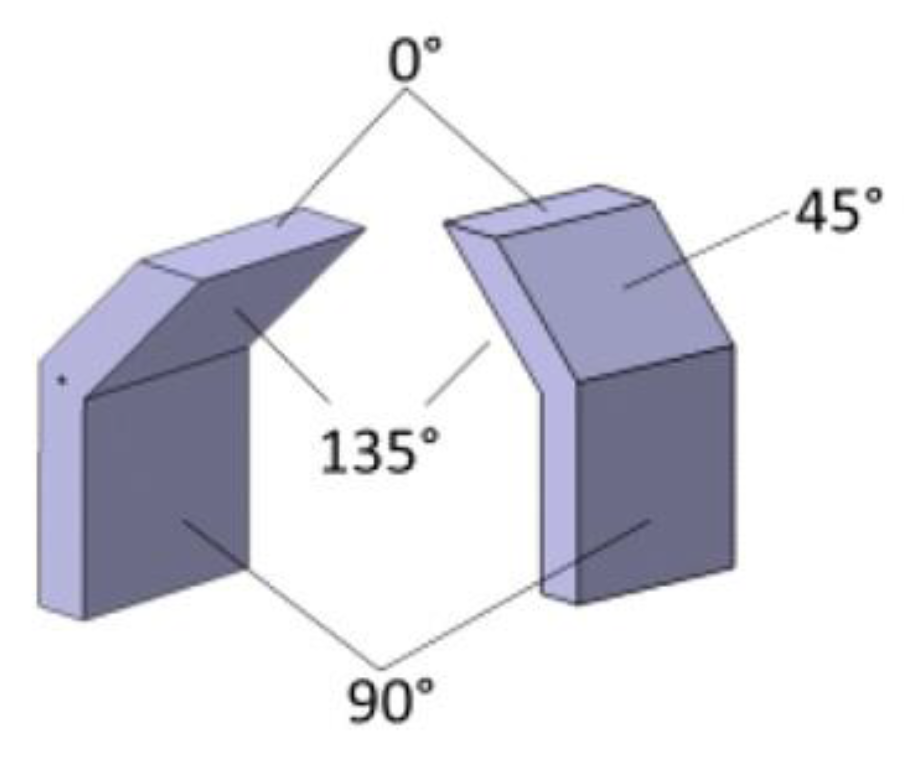
| Inconel 625 LPBF | no | Choline cloride+ethylene glycol (1:2) | 25 °C 30 °C 40 °C 50 °C | 4 h | 160 rpm | 4 V 5 V | 17 µm (135°) 6 µm (90°) 9 µm (45°) 1.4 µm (0° ) | - | 50 °C–4V 6 µm (135°) 2 µm (90°) 2 µm (45°) 1 µm (0°) | 40 °C–5V 10 µm (135°) 3 µm (90°) 5 µm (45 °) 2 µm (0°) |
| Hastelloy LPBF (FLATE PLATE AND CYLINDRICAL TUBE) | no | Choline cloride+ethylene glycol (1:2) | 70 °C | 1–5 min | 400 rpm | 19.5 mA/cm2 | 10.3 ± 0.7 μm (FLATE PLATE) 8–22 μm (CYLINDRICAL TUBE) | - | 1.2 ± 0.1 μm (FLAT PLATE) 1.7–4.5 μm (CYLINDRICAL TUBE) | |
Disclaimer/Publisher’s Note: The statements, opinions and data contained in all publications are solely those of the individual author(s) and contributor(s) and not of MDPI and/or the editor(s). MDPI and/or the editor(s) disclaim responsibility for any injury to people or property resulting from any ideas, methods, instructions or products referred to in the content. |
© 2023 by the authors. Licensee MDPI, Basel, Switzerland. This article is an open access article distributed under the terms and conditions of the Creative Commons Attribution (CC BY) license (https://creativecommons.org/licenses/by/4.0/).
Share and Cite
Acquesta, A.; Monetta, T. Green Approach for Electropolishing Surface Treatments of Additive Manufactured Parts: A Comprehensive Review. Metals 2023, 13, 874. https://doi.org/10.3390/met13050874
Acquesta A, Monetta T. Green Approach for Electropolishing Surface Treatments of Additive Manufactured Parts: A Comprehensive Review. Metals. 2023; 13(5):874. https://doi.org/10.3390/met13050874
Chicago/Turabian StyleAcquesta, Annalisa, and Tullio Monetta. 2023. "Green Approach for Electropolishing Surface Treatments of Additive Manufactured Parts: A Comprehensive Review" Metals 13, no. 5: 874. https://doi.org/10.3390/met13050874