Article

Development of the Al12SiCuFe Alloy Foam Composites with ZrSiO4 Reinforcements at Different Foaming Temperatures

by
Suresh Kumar
1,
Sanjeev Kumar
1,
Pardeep Kumar Nagpal
2,
Sharad Ramdas Gawade
3,
Sachin Salunkhe
4,*,
Udayagiri Chandrasekhar
5 and
João Paulo Davim
6
1
Winner Nippon Leatherette Pvt. Ltd., Baddi, Distt., Solan 173205, India
2
Mechanical Engineering Department, I.K. Gujral Punjab Technical University, Kapurthala 144603, India
3
Sharadchandra Pawar, College of Engineering and Technology, Baramati 412306, India
4
Department of Mechanical Engineering, Vel Tech Rangarajan Sagunthala R & D Institute of Science and Technology, Chennai 600062, India
5
Vice Chairman, NAFEMS India and Adjunct Faculty CPDM Indian Institute of Science, Bangalore 560012, India
6
Department of Mechanical Engineering, Campus Universitário de Santiago, University of Aveiro, 3810-193 Aveiro, Portugal
*
Author to whom correspondence should be addressed.
Metals 2023, 13(4), 685; https://doi.org/10.3390/met13040685
Submission received: 26 January 2023 / Revised: 13 March 2023 / Accepted: 29 March 2023 / Published: 30 March 2023

Abstract

:
Lightweight aluminum composite is a class of foam material that finds many applications. These properties make it suitable for many industries, such as the transportation, aerospace and sports industries. In the present work, closed-cell foams of an Al-Si12CuFe alloy and its composite are developed by a stir casting process. The optimization of the foaming temperature for the alloy and composite foams was conducted in terms of the ligament and node size of the alloy and also the volatility of the zircon with the melt, to provide strength to the cell walls. CaCO3 as a blowing agent was homogeneously distributed in the molten metal without adding any thickener to develop the metal foam. The decomposition rate of CaCO3 is temperature-dependent, which is attributed to the formation of gas bubbles in the molten alloy. Cell structure, such as cell size and cell wall thickness, is controlled by manufacturing process parameters, and both the physical and mechanical properties are dependent on the foam cell structure, with cell size being the major variable. The results show that the increase in cell wall thickness with higher temperature leads to a decrease in cell size. By adding the zircon to the melt, the cell size of the composite foam first increases, and then the thickening of the wall occurs as the temperature is increased. The uniform distribution of the blowing agent in molten metal helps in the formation of a uniform cell structure. In this work, a comparative structural study of alloy foam and composite foam is presented regarding cell size, cell shape and foam stability at different temperatures.

1. Introduction

Metallic foams in some applications exhibit superior properties as compared to metals. Because of their exceptional buckling and impact resistance, these materials are used as sound absorbers and building materials and also in different transport structures [1,2,3]. However, the properties of metal foams are controlled by manufacturing conditions and have paved the path for scientists to partially make their structures by controlling the cell shape in the structure, because cell morphology affects mechanical properties [4,5,6]. Lightweight aluminum and its alloy are not currently being used with steel in the same way as any other metal, so its production continues to grow. Its physical character makes it an ideal candidate for a variety of applications in industries such as packaging, transportation, construction and aerospace [6]. Closed-cell foams do not have interconnected pores. The closed-cell foams normally have higher compressive strength due to their structures. Liquid metal can be foamed directly by the stir casting route with the help of gas-releasing blowing agents. The key lead of this process is the ease, lower manufacturing cost and the possibility of selectively reinforcing the foamed part. Alexandra et al. [7] found that the processing technique depends upon the foaming agent used, which may lead to the formation of different types of cells and also a variation in cell wall thickness. Harders et al. [8] have studied the mechanical properties and variation in the structural parameters of foam cell morphology. In order to improve the strength of foam, the reinforcement of ceramic particles has been performed. Malekjafarian et al. [9] have studied the effect of silicon carbide on the structural parameters of cell morphology, density, and the mechanical performance of foams using CaCO3 as a foaming agent. Some other scientists have explored the influence of temperature and ceramic particles on the size of the cell in Al-foams [10,11,12]. Orbulov et al. [13] produced a low cost and lightweight metal-modified AlSi9MgMn matrix composite foam, with ~60 vol% of various nominal diameter light-expanded clay particles used as fillers in foams for transportation applications. Vesenjak et al. [14] observed the behavior of metallic foam under impact loading and shockwave propagation. Byakova et al. [15] studied the role of foaming agents and processing routes in influencing the contamination of cell wall material by side products. The microscopic mechanism of deformation influences and favors the brittle or ductile behavior of cell walls. Marx et al. [16] investigated the effectiveness of composite metal foam armor against 0.50 caliber ballistic threats. Kubelka et al. [17] investigated the compressive deformation characteristics of Mg-based syntactic foam and analyzed the deformation behavior of the interface between the hollow spheres and the matrix.
We sought to study the effect of foaming temperature on the microstructure of cell structures, which ultimately affects the mechanical properties of composite foams on an industrial scale. Moreover, a small reinforcement of ceramic powder may provide strength to walls of foamed materials. The main aim of the current work is to compare the different structural features of metal alloy foams as well as metal matrix composite foams processed under similar conditions. The idea behind this study is to develop foams with uniform and stronger cell walls through reinforcement with fine-grade zircon sand ceramic powder, which has not been studied so far. The structural features of closed-cell foams have been studied. The results, with variations in foaming temperatures for alloy foams as well as composite foams, are compared. The structure properties of the alloy foam and its composite foam were compared in this study at different temperatures. The microtopography of cell structure was observed, to understand the effect of foaming temperature on the closed-cell mechanism of the alloy foam and its composite foam.

2. Experimental

Materials and Method

In this work, metallic foams were developed by the stir casting technique by adding a blowing agent to the melt. Here, the Al-Si12CuFe alloy was used as a matrix component, CaCO3 was used as a blowing agent, and zircon sand (ZrSiO4) was used as a reinforcement. The first known amount of starting material (Al-Si12CuFe alloy) was charged in a fire clay crucible and the entire assembly was kept inside the furnace. The chemical composition of the Al-Si12CuFe alloy in wt.% is shown in Table 1. The furnace temperature was increased to 800 °C. After that, by using the graphite stirrer for uniform mixture, the melted alloy was stirred up to 630 RPM [18]. A three-blade stirrer was used for mechanical stirring; it helped to generate a vortex inside the liquid alloy at this speed. During rotation, 2 wt.% CaCO3 with a particle size of 1–25 µm was charged inside the vortex in the melt to obtain Al-Si12CuFe alloy foams. For composite foams, 5 wt.% of zircon sand along with 2 wt.% CaCO3 was charged inside the vortex to produce composite foams. The chemical composition of the zircon sand (ZrSiO4) is shown in Table 2. The list of the processing parameters of the developed Al-Si12CuFe alloy foams is shown in Table 3. The particle size of zircon sand was 1–25 µm, which was used as a reinforcement. After charging the materials, the mechanical stirring was continued for five minutes to obtain a homogeneous distribution of foaming agent in the liquid melt, which helped to achieve the uniform distribution of pores in the cast material. CaCO3 decomposes into molten metal at a temperature of approximately 825 °C. The released CO2 gas inside the melt propels and facilitates the foaming process. After stirring, the foamed material was cooled in open air. Density (ρ) measurements were carried out on the Al-Si12CuFe alloy foam and Al-Si12CuFe composite foam using the Archimedes principle, as given below.
ρ = m m m w ρ w
where m belongs to the mass of the foam sample in open air, mw is related to the mass in distilled water of the same foam sample, and ρw is the density of distilled water. The number of cells, size, thickness of cell wall, node size and ligament length were measured with the help of an ink pattern taken from the surface of the foams. The square-shaped foam samples (20 mm × 20 mm × 20 mm) were used to find the number of cells with the help of the ink pattern. The morphology of the metal foam and metal matrix composite foams were further investigated through optical and scanning electron microscope. The composite samples were mechanically polished and etched with Keller’s reagent for a metallographic study. Optical microstructural analysis was used to examine the prepared samples (Eclipse MA-100, Nikon, Tokyo, Japan). A Vickers hardness testing machine was used to determine the microhardness of the composite’s various phases (particles, particle/matrix interface, and matrix) (Mitutoyo, Kanagawa, Japan). Each set of samples was tested for microhardness by taking a minimum of five indentations at 100 gmf on each sample.

3. Results and Discussions

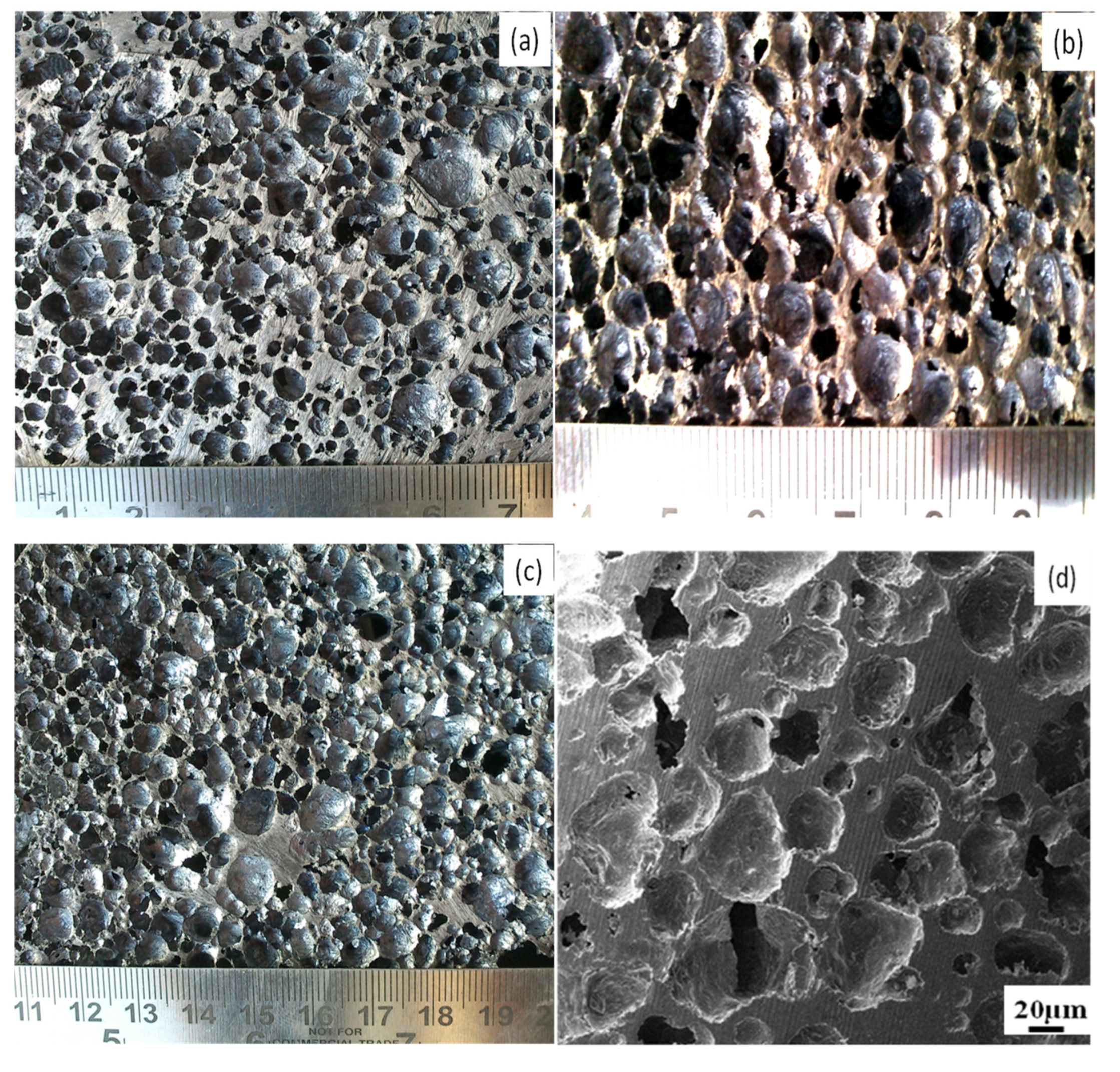
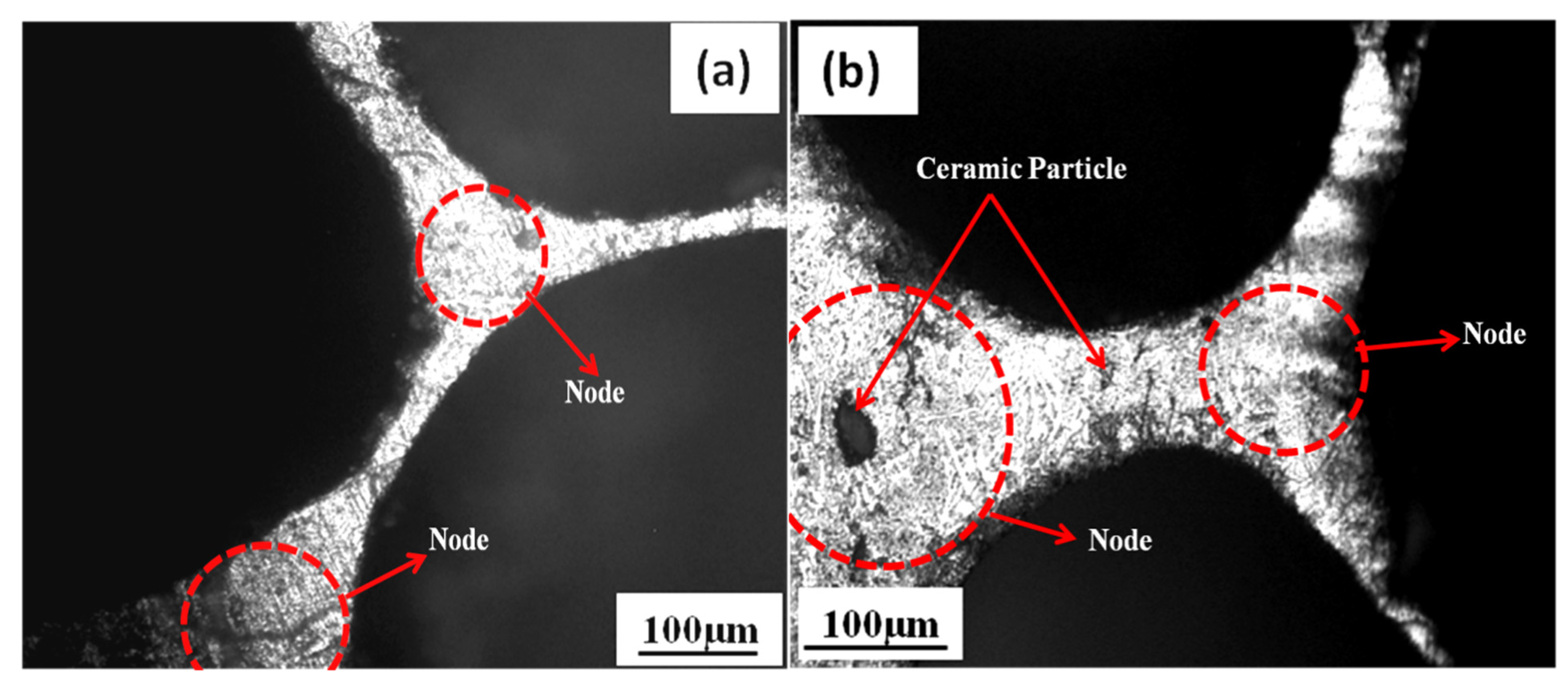
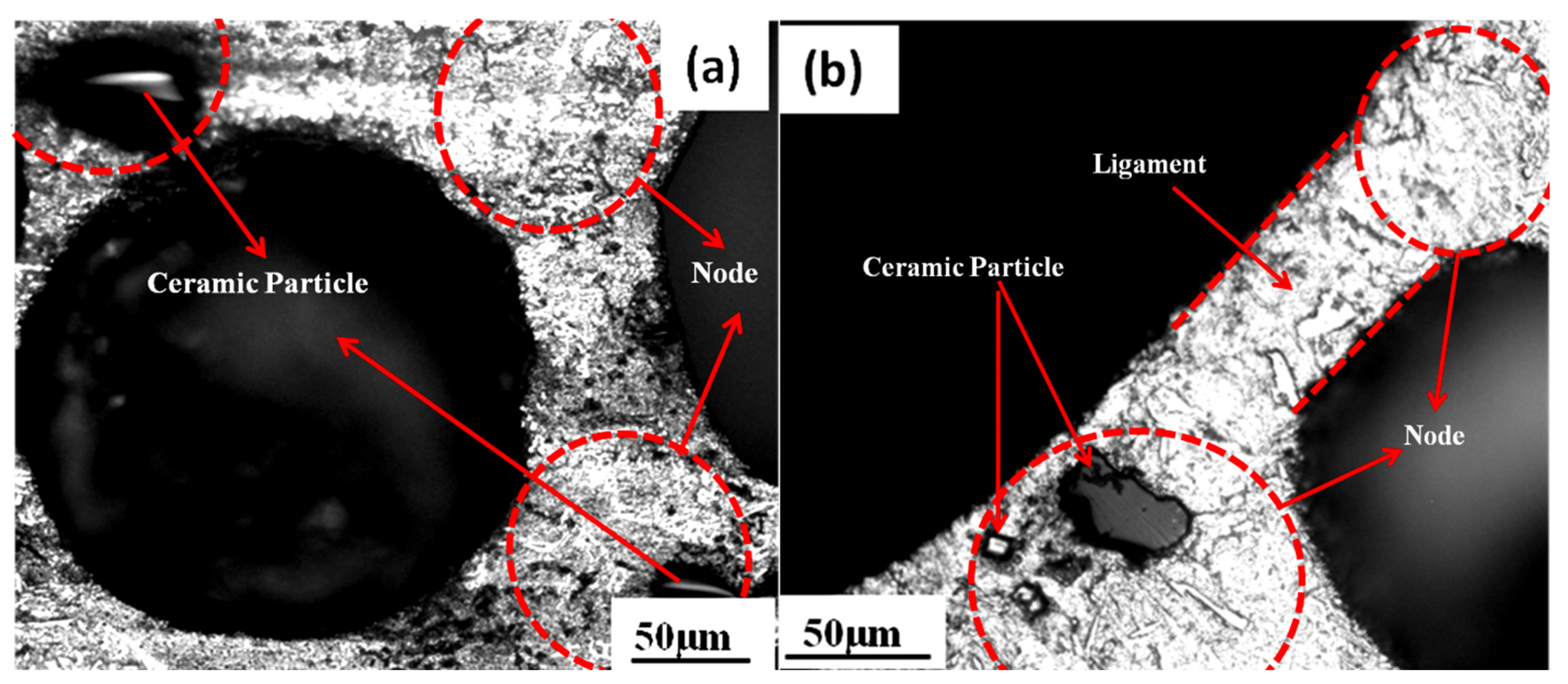
3.1. Influence of Foaming Temperature on the Cell Morphology of Al-Si12CuFe Alloy Foam

As the foaming temperature increased, it was evident that the blowing agent released more gas, resulting in more giant bubbles. However, as the foaming temperature increased, the pressure inside the gas bubble (Pin) also increased. The gas bubbles allow the cell to easily nucleate and grow by lowering the excess pressure (Pc) caused by the molten alloy’s decrease in surface tension ( γ ). For the Al-Si12CuFe alloy, [19] was calculated to describe the change in surface tension with temperature.
γ = 842 0.204   ( T T m )
where γ is the surface tension, T is the foaming temperature, and Tm belongs to the melting temperature of the Al-Si12CuFe alloy, which is shown in Figure 1. Additionally, the viscosity with temperature was calculated for the Al-Si12CuFe alloy as [19]:
η L ( T ) = C exp ( E a / R T )
The alloy type determines the coefficient factor C in the expression, where ηL is the viscosity at temperature (T). The activation energy for a viscous flow, Ea, has a connection to the gas constant, R. Figure 2 displays the temperature-dependent variation in viscosity calculated for the Al-Si12CuFe alloy. Foaming agents were added to the molten Al-Si12CuFe alloy at the correct temperature, where CaCO3 decomposed to release CO2 gas and bubbles were nucleated in the liquid phase. The foaming temperature increased from 850 to 900 °C, increasing the diffusion rate of CaCO3 and the nucleation rate of the gas bubbles. Many gas bubbles formed due to the high gas flow rate in the molten liquid, and the pressure inside each bubble rose as a result. Because of the low viscosity of the molten aluminum at high temperatures, the applied force of the trapped gas inside the pores will be greater than the viscosity force [20]. Figure 3 shows the macrographs of Al-Si12CuFe alloy foams produced at various foaming temperatures. This exposes the wide variation in the structural features of foam with the various foaming temperatures of the Al-Si12CuFe alloy. The structural characteristics of the foam, such as cell wall thickness, cell size average, foaming efficiency, and foam density, changed as the foaming temperature increased. The modifications in structural parameters are usually controlled by the gas bubble formation rate, the size and shape of the bubbles. The structure of the final cells can be controlled by the particle (structure, shape and size, volume fraction), gas (structure and purity), particle–surface interaction, matrix alloy composition and the temperature of the foaming, according to Babcsán et al. [21]. At an 850 °C foaming temperature, there was almost no bubble-free zone. This resulted in a thickened cell structure without any adverse curvature in the Al-Si12CuFe alloy foam (Figure 3a). The equilibrium pressure of carbon dioxide gas increased at 850 °C as the viscosity [1] of the alloy decreased at this temperature, which was sufficient for foaming. The high gas flow rate of CO2 accelerated and moved upward to the surface, leading to a rapid coalescence of the bubbles. The homogeneity of the foam structure for the required porosity is dependent on the CO2 gas generated inside the molten metal [3]. Figure 3b shows the resulting morphology of regularly shaped cells as well as the overgrowth of some cells at the 875 °C foaming temperature. The velocity of the gas flow is inversely proportional to the cross area of origin and proportional to the gas flow [22]. Therefore, an increase in the gas flow rate contributes to an apparent increase in the gas flow velocity and consequently the gas pressure when the core diameter is small [23]. Conversely, an increase in the gas flow rate results in an apparent increase in the gas flow and the gas pressure increases when the diameter of the pore is large. As the temperature rises, the gas pressure also increases. The morphology of the cells shows the hypertrophy of gas bubbles along with uniform growth due to high pressure. The diameter of the cell decreased rapidly beyond 850 °C and the surface tension of the molten melt decreased. In addition, a larger amount of gas was released as the temperature rose [20]. For optimal closed-cell geometry, such as shape and size, an equilibrium between surface tension and gas volume is required. This means that the diffusion rate of the blowing agent has to be controlled in order to obtain the same size and shape as the foam cells. High decomposition rates can lead to the formation of irregularly shaped cells and the hypertrophy of some cells in the foamed aluminum alloy [7]. The dotted line arrow in Figure 3b shows the interconnection of these cells and the overgrowth is shown by the encircled cells. Faster carbon dioxide gas generation and more giant alloy foam cells were achieved by increasing the foaming temperature from 875 °C to 900 °C. At 900 °C, the lower viscosity of the molten Al-Si12CuFe alloy caused the liquid film to thin. Thus, more giant and more unstable air bubbles were created. A drop in maximum liquid pressure caused the bubble to pop as it rose to the surface of the liquid [8]. With increased pressure, the cell wall weakened and collapsed. A greater volume of gas in the molten mass caused it to escape and reduced foaming efficiency. This caused the foamed structure to completely collapse, resulting in the thicker-walled aluminium foam structure shown in Figure 3c. The Al-Si12CuFe alloy foaming temperature is best at 850 °C, according to this study. Figure 3d depicts the laminar structure of an Al-Si12CuFe alloy foam along its walls. In the SEM image of the foam shown in Figure 3d, there are some signs of collapse and a very coarse pore structure in the upper middle portion. Cells collapse when gas diffuses from one cell to another, forming an interconnect path [6]. During solidification, these interconnected cell walls are responsible for the foam’s drainage, rupture, and coarseness [24]. Because the radius of a cell is directly proportional to its internal gas pressure, the formation of different cells results from this relationship. Cell collapse can be seen in the top portion of Figure 3d. The higher the internal pressure, the greater the number of interconnections between cells in the closed-cell foam. The structure shows a cell with a non-uniform shape and thinner cell walls. When gas is released, the cell walls are pressurized uniformly. Cell size and distribution were examined in the closed-cell alloy foam microstructure, as shown in Figure 3e. As shown in the micrograph, the cell size of alloy foam at 850 °C is notable, with thinner cell faces shown by the dotted lines. Foam cells developed ligaments and nodes, which are visible. Because the melt alloy’s viscosity decreased due to the increased foaming temperature, the cell walls became thinner. The Al-Si12CuFe alloy foaming temperature increased during the foaming stage, resulting in a rise in gas pressure that led to an over-pressure along the walls of the bubble. As a result, the cell wall’s movement within the liquid was easily distorted because of the low pressure in the ligament. The cell wall thinned due to the increased pressure inside the cell, which eventually caused the cell to rupture. Figure 3e shows that the cell walls coalesced, and the effect is visible. Figure 3f shows the curvature of the cell wall changing due to pressure differences between two cells. Metal flow occurs from higher to lower, resulting in a non-uniform curvature at lower pressures. Table 4 shows how the structural parameters of the Al-Si12CuFe alloy foam changed as the foaming temperature rises or falls. The viscosity and surface tension of the melt determine the cell size of the Al-Si12CuFe alloy. Both surface tension and viscosity decrease with temperature, as shown in Figure 1 and Figure 2. A gas bubble in the liquid Al-Si12CuFe alloy is subjected to four forces. The Al-Si12CuFe alloy’s internal gas pressure (Pin) is responsible for increasing the gas bubble’s diameter. At this equilibrium condition, gas bubbles were reduced in size by a combination of metallostatic, atmospheric, and surface tension forces (Pst) [24].
Pin = Pm + Pa + Pst
The cell size of Al-Si12CuFe alloy foams is obtained by
r = 2 γ/Pst
where ‘r’ is the radius of the bubble and ‘γ’ and ‘Pst’ are the surface tension and surface tension force, respectively. Figure 4 illustrates that the cell size of alloy foam increases as the foaming temperature rises due to a decrease in the melt alloy’s surface tension. Adding a blowing agent to a liquid alloy may cause an increase in porosity because of the interactions between carbon dioxide gas and liquid alloy [25]. Based on the foam’s surface tension and viscosity, the theoretical results of the comparison study are presented. The surface tension and viscosity of the Al-Si12CuFe alloy foam decrease as the foaming temperature rises. The Al-Si12CuFe alloy’s surface tension (805.28 mN/m) and viscosity (1.635 mPa-s) are perfectly balanced at 850 °C to produce foam with a uniform cell size. Due to a decrease in surface tension and viscosity, the Al-Si12CuFe alloy foam cell size is not uniform when heated from 850 °C to 875 °C and 900 °C. This alloy’s molten liquid film thins out due to surface tension and viscosity reduction. When bubbles collapse at 900 °C, a more densely packed liquid alloy foam is formed with thicker walls.

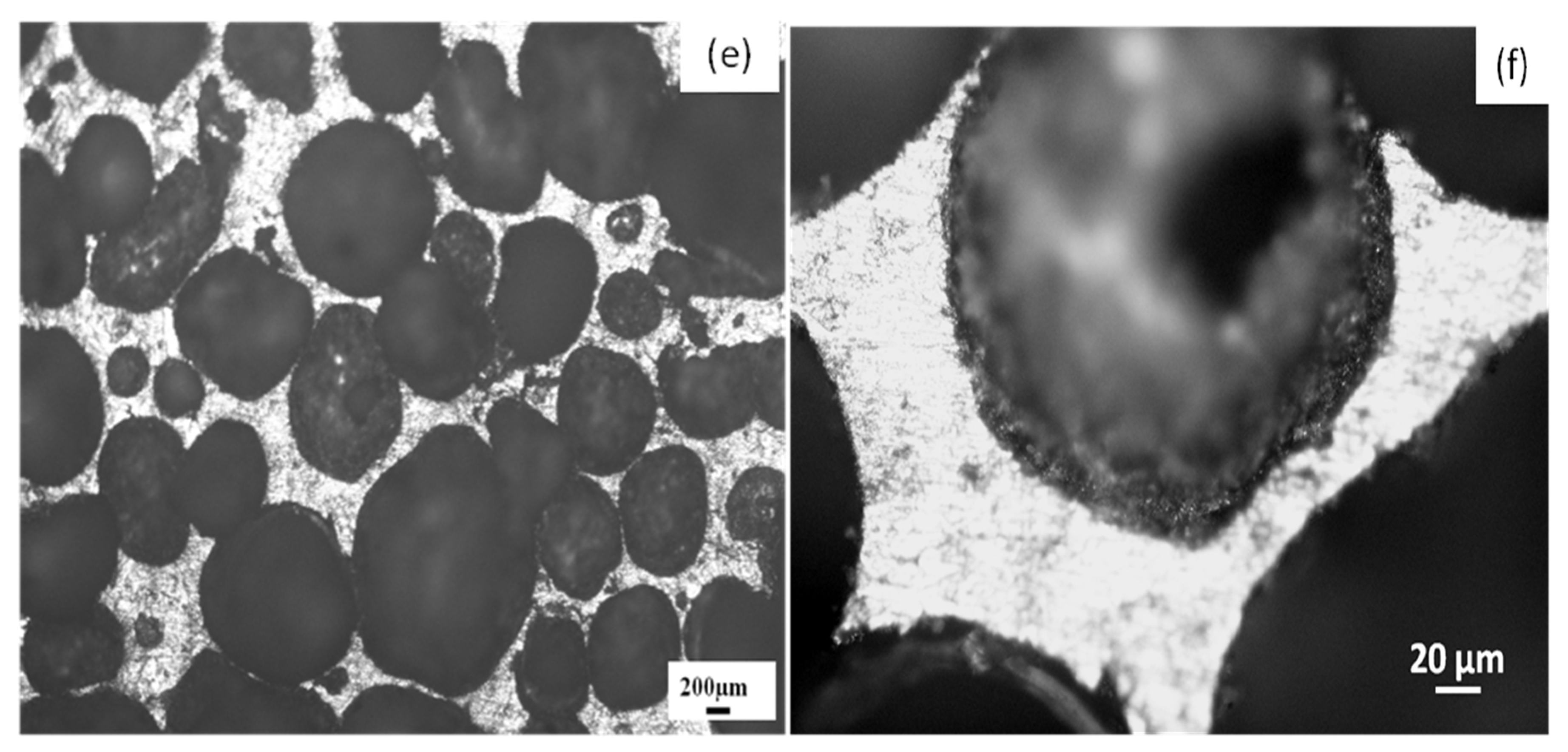
3.2. Influence of Ceramic Particles and Foaming Temperature on the Cell Geometry of Composite Foam

Figure 5 shows the microstructure of composite foam made at 850 °C, 875 °C, and 900 °C. Cell geometry and distribution uniformity affect the mechanical properties of the composite foam. Smaller, more uniformly distributed cells are more vital. Using ceramic powder as a reinforcing agent in composite foams allows for precise control over cell geometry and distribution, resulting in robust structures that can withstand solidification without collapsing or merging. There must be a balance between the material’s viscosity and surface tension if the composite foam is stable. The viscosity of composite propellant slurries reinforced with zircon sand varies with temperature. The sand’s composition, shape, and topography also play a role.
High viscosity is caused by the liquid’s inability to drain quickly. It affects the thickness of the cell wall. The cell wall thickness is reduced by gravity and low surface tension. Ceramic particles have a significant impact on viscosity. Einstein’s viscosity equation [26] shows a connection between ceramic particle volume fraction and relative viscosity.
η C = η L [ 1 + 2.5 φ + 10.25 φ 2 + A e x p ( B φ ) ]
The initial viscosity ηL of the melted Al-Si12CuFe is A = 0.002732 and B = 16.6. The solid volume fraction φ, ηC is the viscosity of the composite. The higher viscosity of the melted Al-Si12CuFe alloy is attributed to the higher volume fraction of ceramic particles. However, the ceramic particles should not settle to the bottom of the mixer in the mold for uniform distribution [27]. Temperature is an essential factor in how much the solid and liquid phases lubricate each other, which in turn affects composite viscosity (Figure 6). Surface tension and viscosity, according to Pelofsky [28], have the following relationship:
I n σ = I n A + B η C
For example, in A and B, the substance-dependent constants are σ and ηC, respectively. With the help of Equation, we discovered a connection between surface tension and viscosity (7). For this reason, we modified Equation (7) to find the data’s correct value. Figure 7 depicts the functional relationship between surface tension and composite foam temperature using Equation (7).
The viscosity and stability of bubbles are affected by the foaming temperature. However, the wettability of the solid and liquid phases impacts the thickening and bubble stability of the mixture [29]. The energy balance at the melt–zircon particle interface determines the location and distribution of zircon particles on the cell wall and node. The effect of gas reactions on the cell wall surface and the number of ceramic particles responsible for increasing foamability have been studied. The viscosity of the liquid Al-Si12CuFe alloy increased when 5 wt.% ceramic particles were added. The decomposition of CaCO3 under these conditions resulted in lower released gas pressure than that with the Al-Si12CuFe alloy as a starting point. The bubble-like structure is formed when CO2 gas expands inside the liquid alloy [30]. The reinforced ceramic particles strengthen the cell wall. At 850 °C, a mixture of 2 wt.% blowing agent and 5 wt.% ceramic particles failed to produce enough pressure to produce composite foam with uniform cell size (Figure 5a). The cell size, porosity and viscosity of the Al-Si12CuFe alloy composite foam sample are observed to change as a function of foaming temperature. Because of the small amount of CO2 gas produced, porosity varied slightly below 875 °C. The temperature directly impacts foaming agent degradation and liquid surface tension [31]. Viscosity and surface tension decrease as the temperature rises. As a result, the bubbles’ stability is reduced due to the higher decomposition rate of the foaming agent. The variation in microhardness of the LM13 alloy foam and its composite foam, in different phases and at various foaming temperatures, is shown in Table 5. The size of the interface is sufficient for the microhardness measurement because during the measurement of microhardness, the indent marking at the center of the interface between the particles (reinforced phase) and the alloy (matrix phase) was considered. There was an increase in the cell size of closed-cell composite foam as the viscosity of melt decreased, with an increase in foaming temperature from 850 °C to 875 °C, as shown in Figure 5b. It is easier for a liquid film to flow when the surface tension is lower at higher temperatures [32]. As a result of this, the length of the ligament and the size of the nodes both increased [33]. The foaming temperature was raised from 875 °C to 900 °C, but little change was seen in the cell microstructure, as shown in Figure 5c (smaller node size and longer ligament length). The addition of zircon particles altered the cell size by increasing the flow rate of CO2 gas. Foaming occurred at a higher temperature because the decomposition of CaCO3 is more rapid at a higher temperature (900 °C). Viscosity decreased and the CaCO3 decomposition rate increased, making cell formation easier [34,35]. This is responsible for producing foams with consistent cell sizes and long-term stability (Figure 5c). Foam stability largely depends on the volume of gas that ruptures the cell wall and drains out, provided by the wettability of zircon particles with liquid alloy. Foam stability is affected by the zircon sand size, shape, and gas drainage quantity leading to cell rapture. Because of the higher viscosity, it takes longer for the liquid alloy to flow, resulting in slower cell wall drainage before it solidifies [36]. Adding ZrSiO4 particles to the liquid alloy composite, shown in Figure 5d, increased viscosity and added thickness to the cell walls. With the addition of ceramic particles, Jaroslav and Alexandr [27] found that the viscosity in the composite progressively increases.
Since the molten metal released gas most efficiently at 900 °C (see Figure 5e), the composite foam has a uniform cell size. When incorporated into the melt, ceramic particles influenced viscosity while providing foam structural stability [37]. A decrease in internal pressure at the cell-to-cell interface resulted in a change in curvature [38]. As shown in Figure 5f, the node size and cell wall thickness were more sensitive to changes in gas bubble size. The result was increased melting viscosity and an impediment to flow between cells and ligaments. Cell wall drainage increased and a thicker cell wall was formed [8,9]. Due to surface tension, a liquid film acted as an interface, to keep two adjacent bubbles apart. The viscosity of a liquid alloy is directly related to the surface tension of the film [7]. The cell size of the composite foam appeared to increase the node size and the length of the ligaments [38]. In addition, compared to alloy foam cells, an 850 °C foaming temperature appears to have had the least impact on ligament length and node size versus composite foam cell size (Figure 8a,b). Due to the addition of ceramic particles, the gas flow rate indicated that the cell size had changed. As shown in Figure 9a,b, the strength of cell walls increases due to the presence of ceramic particles on the cell walls and at the nodes.
For this reason, the cell wall can hold some ceramic particles while the node’s remaining particles move towards it. This type of distribution is possibly due to the Coanda effect [39] and the fact that fluid follows the counter. Al-Si12CuFe alloy composite foams may have different cell sizes, nodes, and ligaments. Because of the ZrSiO4 particles, the foam is more stable, allowing easier manipulation.
Al-Si12CuFe alloy composite foam’s viscosity (2.055 mPa-s) and surface tension (832.43 mN/m) are not high enough at 850 °C to produce uniform cell size. As the viscosity and surface tension of the liquid decrease with an increase in foaming temperature from 850 °C to 875 °C and 900 °C, the cell size of composite foam increases. Cell formation is facilitated by the melted Al-Si12CuFe alloy composite’s lower viscosity (1.88 mPa-s) and surface tension (825.12 mN/m). The decrease in viscosity and surface tension at this temperature leads to stable foams with uniform cell size.

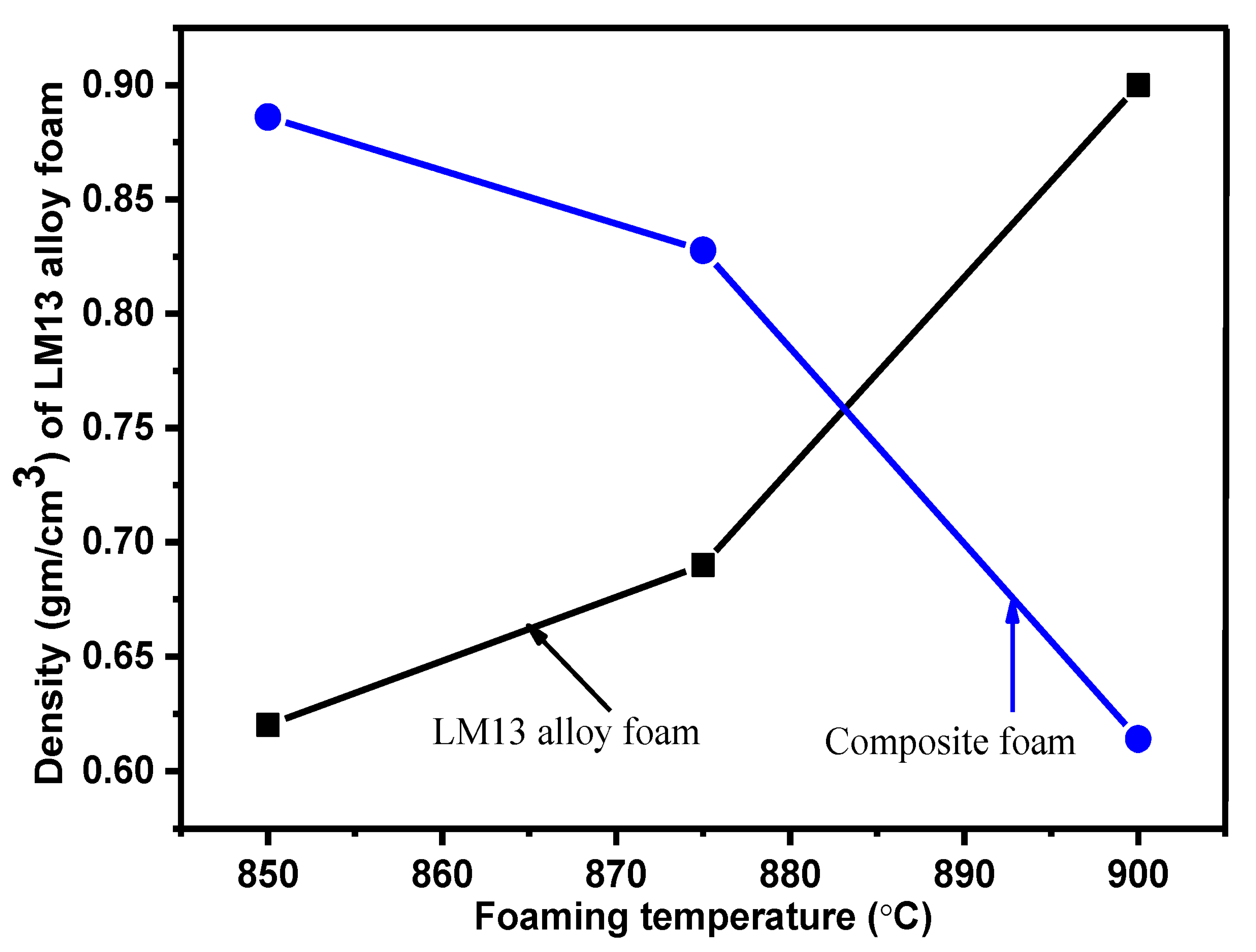
3.3. Influence of Foaming Temperature on the Density of Al-Si12CuFe Alloy and Composite Foamed Structures

The density of Al-Si12CuFe alloy foam increases, but for composite foam it decreases with increasing foaming temperature, which is shown in Figure 10. The addition of the zircon particles in the liquid Al-Si12CuFe alloy provides the stability to foam walls. The wettability between the zircon particle and the liquid Al-Si12CuFe alloy is not only due to the influential properties of the zircon particle with liquid Al-Si12CuFe alloy, but the drainage and rupture nature are affected by the foam stability. The foam stability generally depends on the cell wall separating the gas bubbles [5]. The viscosity is increased with the addition of zircon particles in liquid Al-Si12CuFe alloy. The velocity of the gas flow is inversely proportional to the cross area of origin and proportional to the gas flow [22]. Therefore, an increase in the gas flow rate contributes to an apparent increase in the gas flow velocity and consequently the gas pressure when the temperature is increased [23]. Conversely, an increase in the gas flow rate results in an apparent increase in the gas flow and the gas pressure increases when the temperature is increases. A molten metal with high viscosity is responsible for slowing down the liquid flow and thus inhibits the cell wall drainage during the solidification. Apart from their effect on liquid viscosity, the zircon particles increase the stability of the foam through their attachment, which depends on the type of interface between the liquid alloy and CO2 gas in Al-Si12CuFe alloy composite foam. This attachment of ceramic particles changes the shape of interfacial curvatures and decreases the capillary pressure difference between the ligament and cell wall of the Al-Si12CuFe alloy composite foam. The increment in the thickness of cell wall is due to the higher viscosity of the liquid Al-Si12CuFe alloy with the addition of ceramic particles. Moreover, the higher aggregation of zircon particles in the melt and particle interface generates a tortuous path for the melt alloy. This provides a barrier in the melt alloy from the cell wall to the ligament boundary [6]. As a result, cell wall drainage is inhibited, thus resulting in the increment in thickness of the cell wall and decrement in the ligament border. The increase in foaming temperature decreases the density of the Al-Si12CuFe alloy composite foam. As the temperature is increased, viscosity decreases, and the gas trapped in the liquid foam expands. This causes a reduction in the thickness of the cell wall, with larger cell size. Ultimately, the density of the developed foam decreases.

4. Conclusions

We have successfully developed a lightweight foam of the Al-Si12CuFe alloy and its composite at different foaming temperatures. The influence of the foaming temperature on the decomposition rate of the blowing agent, density, viscosity, foam stability with ceramic particles, and Al-Si12CuFe alloy foam and composite foam structures was studied.
The cell size of Al-Si12CuFe alloy foam decreases with increases in temperature from 850 °C to 900 °C. However, for zircon sand-reinforced composite foam, it increases in this temperature range. The optimized condition for obtaining closed-cell foams of uniform size of the Al-Si12CuFe alloy is 850 °C, whereas for zircon sand-reinforced composite foams it is 900 °C. It was observed that the blowing agent with different decomposition rates at different foaming temperatures directly influenced the morphology of both Al-Si12CuFe alloy foam and composite foams. Foaming temperature affects the foam stabilization, which further depends on the wettability of ceramics particles and melts. Higher foaming temperature is responsible for lowering the viscosity of the composite melts, which causes the formation of thinner cell walls in the metal foam. The foam density is decreased due to the formation of thin cell walls, having larger cell size with increased foaming temperature.

Author Contributions

Conceptualization, S.K. (Suresh Kumar), S.K. (Sanjeev Kumar) and P.K.N.; methodology, S.K. (Suresh Kumar), S.K. (Sanjeev Kumar), P.K.N., S.R.G. and S.S.; software, S.S. and U.C.; validation, S.K. (Suresh Kumar), S.K. (Sanjeev Kumar), P.K.N., S.R.G. and S.S.; formal analysis, S.R.G. and S.S.; investigation, S.K. (Suresh Kumar), S.K. (Sanjeev Kumar), P.K.N., S.R.G. and S.S.; resources, S.K. (Suresh Kumar), S.K. (Sanjeev Kumar), P.K.N., S.R.G. and S.S.; data curation, S.K. (Suresh Kumar), S.K. (Sanjeev Kumar), P.K.N., S.R.G. and S.S.; writing—original draft preparation, S.K. (Suresh Kumar), S.K. (Sanjeev Kumar), P.K.N., S.R.G. and S.S., U.C. and J.P.D.; writing—review and editing, S.K. (Suresh Kumar), S.K. (Sanjeev Kumar), P.K.N., S.R.G. and S.S., U.C. and J.P.D.; visualization, S.K. (Suresh Kumar), S.K. (Sanjeev Kumar), P.K.N., S.R.G. and S.S., U.C. and J.P.D.; supervision, S.K. (Suresh Kumar), S.K. (Sanjeev Kumar), and S.S., U.C. and J.P.D.; project administration, S.K. (Suresh Kumar), S.K. (Sanjeev Kumar), P.K.N., S.R.G. and S.S., U.C. and J.P.D.; funding acquisition, S.S., U.C. and J.P.D. All authors have read and agreed to the published version of the manuscript.

Funding

This research received no external funding.

Institutional Review Board Statement

Not Applicable.

Informed Consent Statement

Not Applicable.

Data Availability Statement

Not Applicable.

Acknowledgments

The authors are thankful to Ritu Singla, Chairman and Managing Director of Winner Nippon Leatherette Pvt Ltd., a unit of the Raglan Group, for providing various support for this study within our R&D laboratory and Armament Research Board (ARMREB), Defence Research and Development Organization (DRDO), Terminal Ballistics Research Laboratory (TBRL), Chandigarh India for providing financial support under the letter no. ARMREB CDSW/2012/148 for this study.

Conflicts of Interest

The authors declare no conflict of interest.

References

  1. Gupta, N.; Rohatgi, P.K. Metal Matrix Syntactic Foams: Processing, Microstructure, Properties and Applications; DEStech Publications: Lancaster, PA, USA, 2014. [Google Scholar]
  2. Hernández-Nava, E.; Smith, C.J.; Derguti, F.; Tammas-Williams, S.; Leonard, F.; Withers, P.J.; Todd, I.; Goodall, R. The effect of density and feature size on mechanical properties of iso-structural porous metals produced by additive manufacturing. Acta Mater. 2015, 85, 387–395. [Google Scholar] [CrossRef] [Green Version]
  3. Raj, R.E.; Daniel, B.S.S. Aluminum Melt Foam Processing for Light-Weight Structures. Mater. Manuf. Process. 2007, 22, 525–530. [Google Scholar] [CrossRef]
  4. Gibson, L.J. Mechanical Behavior of Metallic Foams. Annu. Rev. Mater. Sci. 2000, 30, 191–227. [Google Scholar] [CrossRef]
  5. Deqing, W.; Weiwei, X.; Xiangjun, M.; Ziyuan, S. Cell structure and compressive behavior of an aluminum foam. J. Mater. Sci. 2005, 40, 3475–3480. [Google Scholar] [CrossRef]
  6. Rivera, N.M.T.; Torres, J.T.; Valdés, A.F. A-242 Aluminium Alloy Foams Manufacture from the Recycling of Beverage Cans. Metals 2019, 9, 92. [Google Scholar] [CrossRef] [Green Version]
  7. Byakova, A.; Kartuzov, I.; Gnyloskurenko, S.; Nakamura, T. The Role of Foaming Agent and Processing Route in Mechanical Performance of Fabricated Aluminum Foams. Adv. Mater. Sci. Eng. 2014, 4, 109–114. [Google Scholar] [CrossRef] [Green Version]
  8. Harders, H.; Hupfer, K.; Rösler, J. Influence of cell wall shape and density on the mechanical behaviour of 2D foam structures. Acta Mater. 2005, 53, 1335–1345. [Google Scholar] [CrossRef]
  9. Malekjafarian, M.; Sadrnezhaad, S. Closed-cell Al alloy composite foams: Production and characterization. Mater. Des. 2012, 42, 8–12. [Google Scholar] [CrossRef]
  10. Han, F.; Wei, J.; Cheng, H.; Gao, J. Effects of process parameters and alloy compositions on the pore structure of foamed aluminum. J. Mater. Process. Technol. 2003, 138, 505–507. [Google Scholar]
  11. Wen-Yea, J.; Wen-Yen, H.; Ching-Chien, M.; Yu-Chang, Y. Microstructure and mechanical properties of ALPORAS closed-cell aluminium foam. Mater. Charact. 2015, 107, 228–238. [Google Scholar]
  12. Vendra, L.J.; Brown, J.A.; Rabiei, A. Effect of processing parameters on the microstructure and mechanical properties of Al–steel composite foam. J. Mater. Sci. 2011, 46, 4574–4581. [Google Scholar] [CrossRef]
  13. Orbulov, I.N.; Szlancsik, A.; Kemény, A.; Kincses, D. Low-Cost Light-Weight Composite Metal Foams for Transportation Applications. J. Mater. Eng. Perform. 2022, 31, 6954–6961. [Google Scholar] [CrossRef]
  14. Vesenjak, M.; Borovinšek, M.; Ren, Z.; Irie, S.; Itoh, S. Behavior of Metallic Foam under Shock Wave Loading. Metals 2012, 2, 258–264. [Google Scholar] [CrossRef] [Green Version]
  15. Byakova, A.; Gnyloskurenko, S.; Nakamura, T. The Role of Foaming Agent and Processing Route in the Mechanical Performance of Fabricated Aluminum Foams. Metals 2012, 2, 95–112. [Google Scholar] [CrossRef] [Green Version]
  16. Marx, J.; Portanova, M.; Rabiei, A. Performance of Composite Metal Foam Armors against Various Threat Sizes. J. Compos. Sci. 2020, 4, 176. [Google Scholar] [CrossRef]
  17. Kubelka, P.; Kádár, C.; Jost, N. Effect of the interface on the compressive properties of magnesium syntactic foams. Mater. Lett. 2021, 287, 129293. [Google Scholar] [CrossRef]
  18. Kumar, S.; Panwar, R.S.; Pandey, O. Effect of dual reinforced ceramic particles on high temperature tribological properties of aluminum composites. Ceram. Int. 2013, 39, 6333–6342. [Google Scholar] [CrossRef]
  19. Kubo, K.; Pehlke, R.D. Mathematical modeling of porosity formation in solidification. Met. Mater. Trans. B 1985, 16, 359–366. [Google Scholar] [CrossRef]
  20. Keith, J.L. The Development of the Arrhenius equation. J. Chem. Educ. 1984, 61, 494–498. [Google Scholar]
  21. Babcsán, N.; Leitlmeier, D.; Degischer, H.P. Foamability of Particle Reinforced Aluminum Melt. Mater. Sci. Eng. Technol. 2003, 34, 22–29. [Google Scholar] [CrossRef]
  22. Kulkarni, A.A.; Joshi, J.B. Bubble Formation and Bubble Rise Velocity in Gas−Liquid Systems: A Review. Ind. Eng. Chem. Res. 2005, 44, 5873–5931. [Google Scholar] [CrossRef]
  23. Mohseni, E.; Kalayathine, J.J.; Reinecke, S.F.; Hampel, U. Dynamics of bubble formation at micro-orifices under constant gas flow conditions. Int. J. Multiph. Flow 2020, 132, 103407. [Google Scholar] [CrossRef]
  24. Anson, J.P.; Drew, R.A.L.; Gruzleski, J.E. The surface tension of molten aluminum and Al-Si-Mg alloy under vacuum and hydrogen atmospheres. Met. Mater. Trans. B 1999, 30, 1027–1032. [Google Scholar] [CrossRef]
  25. Mukherjee, M. Evolution of Metal Foams during Solidification. Master’s Thesis, Technische Universität Berlin, Berlin, Germany, 2009. [Google Scholar]
  26. Singh, M.P.; Singh, R.K. Correlation between ultrasonic velocity, surface tension, density and viscosity of ionic liquids. Fluid Phase Equilibria 2011, 304, 1–6. [Google Scholar] [CrossRef]
  27. Jaroslav, K.; Alexandr, F. Modeling of particle settling in high viscosity liquid. Ceram. Silik. 2001, 45, 70–75. [Google Scholar]
  28. Pelofsky, A.H. Surface Tension-Viscosity Relation for Liquids. J. Chem. Eng. Data 1966, 11, 394–397. [Google Scholar] [CrossRef]
  29. Gergely, V.; Curran, D.C.; Clyne, T.W. The FOAMCARP Process: Foaming of aluminum MMCs by the chalk-aluminum reaction in precursors. Compos. Sci. Technol. 2003, 63, 2301–2310. [Google Scholar] [CrossRef]
  30. Bo-Youn, H.; Soo-Han, P.; Arai, H. Viscosity and surface tension of al and effects of additional element. Mater. Sci. Forum. 2003, 439, 51–56. [Google Scholar]
  31. Matijasevic, L.B.; Banhart, J. Improvement of aluminium foam technology by tailoring of blowing agent. Scr. Mater. 2006, 54, 503–508. [Google Scholar] [CrossRef]
  32. Banhart, J. Metal Foams: Production and Stability. Adv. Eng. Mater. 2006, 8, 781–794. [Google Scholar] [CrossRef]
  33. Simone, A.; Gibson, L. Aluminum foams produced by liquid-state processes. Acta Mater. 1998, 46, 3109–3123. [Google Scholar] [CrossRef]
  34. Yang, C.; Nakae, H. Foaming characteristics control during production of aluminum alloy foam. J. Alloys Compd. 2000, 313, 188–191. [Google Scholar] [CrossRef]
  35. Zohair, S.; Mehdi, S. Influences of titanium hydride (TiH2) content and holding temperature in foamed pure aluminum. Mater. Manuf. Process. 2009, 24, 590–593. [Google Scholar]
  36. Kumar, S.; Pandey, O. Role of fine size zircon sand ceramic particle on controlling the cell morphology of aluminum composite foams. J. Manuf. Process. 2015, 20, 172–180. [Google Scholar] [CrossRef]
  37. Bayani, H.; Mirbagheri, S. Strain-hardening during compression of closed-cell Al/Si/SiC + (TiB2 & Mg) foam. Mater. Charact. 2016, 113, 168–179. [Google Scholar] [CrossRef]
  38. Hajduchova, Z.; Pach, L.; Kozankova, J.; Lokaj, J. Polyhedral alumina foam. J. Porous Mater. 2013, 20, 595–600. [Google Scholar] [CrossRef]
  39. Reba, I. Applications of the Coanda Effect; Scientific American Inc.: New York, NY, USA, 1966; Volume 214, pp. 84–92. [Google Scholar]
Figure 1. The effect of foaming temperature on the surface tension of the LM13 alloy foams.
Metals 13 00685 g001
Figure 2. The effect of foaming temperature on the viscosity of the LM13 alloy foams.
Metals 13 00685 g002
Figure 3. The images of aluminum alloy foam with 2 wt.% blowing agent CaCO3 at (a) 850 °C, (b) 875 °C, (c) 900 °C, (d) SEM image of 850 °C foam and (e) and (f) optical image of LM13 alloy foam of 850 °C.
Metals 13 00685 g003
Figure 4. The effect of foaming temperature on the gas pressure inside bubble in the melt LM13 alloy.
Metals 13 00685 g004
Figure 5. The images of aluminum foam composites with 2 wt.% blowing agent CaCO3 at (a) 850 °C, (b) 875 °C, (c) 900 °C, (d) SEM image; and optical images (e) and (f) of composites foam at 900 °C.
Metals 13 00685 g005aMetals 13 00685 g005b
Figure 6. The effect of foaming temperature on the viscosity of the LM13 alloy and composite foams.
Metals 13 00685 g006
Figure 7. The effect of foaming temperature on the surface tension of the LM13 alloy composite foams.
Metals 13 00685 g007
Figure 8. The images of ligament and node of (a) LM13 alloy foam and (b) composites foam at 850 °C.
Metals 13 00685 g008
Figure 9. The images of ceramic reinforced particles on the ligament of composites foam cell at (a) 875 °C and (b) 900 °C.
Metals 13 00685 g009
Figure 10. The effect of foaming temperature on the density of LM13 alloy and composite foam.
Metals 13 00685 g010
Table 1. Alloy in wt.%.
LM13 AlloySiFeCuMnMgZnTiNiPbSnAl
Wt.%11.80.31.20.40.90.20.020.90.020.005Balance
Table 2. Chemical composition of the zircon sand (ZrSiO4).
ElementsZrO2SiO2TiO2Fe2O3
% in Bulk65.3032.800.270.12
Table 3. List of parameters of the developed metal foams.
List of Processing Parameters for Foaming
Temperature at the time of addition of zircon sand750 °C
Temperature at the time of addition of blowing agent750 °C
Foaming temperature900 °C
Particle size of zircon sand1–25 µm
Particle size of blowing agent1–25 µm
No. of blades in stirrer3
Blade angles of stirrer45°
RPM of stirrer630
Height of the stirrer in the melt2/3 inside the melt
Table 4. Effect of the amount of zircon sand on the cell parameters and density of LM13 alloy foam and its composite foams (subscript ‘f’ shows for fine particles).
LM13 Alloy/Composite FoamAmount of Zircon Sand ParticlesDensity
(gm/cm3)
Average
Cell Size
(mm)
Average Cell Wall Thickness
(µm)
Average Ligament Length (mm)
LM13 alloy foam0.00.902.503001.15
LM13/2.5fZrSiO42.5 wt.% Fine0.842.63101.85
LM13/5fZrSiO45 wt.% Fine0.784.01702.30
LM13/7.5fZrSiO47.5 wt.% Fine1.213.53201.40
LM13/10fZrSiO410 wt.% Fine1.323.13701.65
LM13/12.5fZrSiO412.5 wt.% Fine1.422.74501.80
LM13/15fZrSiO415 wt.% Fine1.532.47401.55
Table 5. Variation in microhardness of LM13 alloy foam and its composite foam different phases of composite foam (subscript ‘f’ shows for fine particles).
Microhardness (Hv)
LM13 Alloy/Composite FoamAt ParticleAt MatrixAt InterfaceAt Node
LM13 alloy foam-69.49-69.60
LM13/2.5fZrSiO4652.4578.54118.7278.91
LM13/5fZrSiO4667.2285.60130.9286.40
LM13/7.5fZrSiO4670.5186.56132.1288.79
LM13/10fZrSiO4666.7488.12133.6790.78
LM13/12.5fZrSiO4671.3489.34136.6791.55
LM13/15fZrSiO4672.2290.56139.1293.54
Disclaimer/Publisher’s Note: The statements, opinions and data contained in all publications are solely those of the individual author(s) and contributor(s) and not of MDPI and/or the editor(s). MDPI and/or the editor(s) disclaim responsibility for any injury to people or property resulting from any ideas, methods, instructions or products referred to in the content.

