Article

Experimental Study on Anchoring Performance of Short-Lapped-Rebar Splices with Pre-Set Holes and Spiral Hoops

1
School of Civil Engineering, Anhui University of Technology, Ma’anshan 243032, China
2
School of Civil Engineering, Chang’an University, Xi’an 710061, China
*
Authors to whom correspondence should be addressed.
Metals 2023, 13(3), 530; https://doi.org/10.3390/met13030530
Submission received: 12 February 2023 / Revised: 3 March 2023 / Accepted: 4 March 2023 / Published: 6 March 2023
(This article belongs to the Topic Microstructure and Properties in Metals and Alloys)

Abstract

:
The precast concrete structure has the advantage of a short construction period, less labor consumption, and less pollution. The lapped-rebar splice is a type of connection for assembled reinforced concrete shear walls in the precast concrete structure. In this study, the anchoring performance of a short-lapped-rebar splice with a corrugated metal duct and spiral hoops is investigated. A total of 30 specimens were designed considering the influences of the rebar diameter and the lapped length, and the tension testing of the splice was carried out. The results show that the specimens with 0.15 times the suggested length in GB 50010-2010 fail by the fracture of rebar, while the specimens with 0.1 times and 0.05 times the suggested length show the pull-out failure of rebar. The ultimate bond strength of specimens with the suggested length is higher than that of the conventional specimens. The stress of the anchored rebar in the short-lapped-rebar splices is distributed symmetrically along the longitudinal direction. The maximum bond stress of the anchored rebar reaches 35 MPa, which is approximately 1.4 times that in the conventional specimens. A semi-empirical model for predicting the ultimate bond strength of the short-lapped-rebar splice is proposed, and it shows good agreement with tested values; the average error estimated from the proposed model is only 4.49%.

1. Introduction

Due to the application of quick-assembled rebar technology (i.e., grouted sleeve connections, metal or plastic duct connections, post-tensioned connections, and steel plate connections), the precast concrete structures were developed rapidly in China. As corrugated metal duct connections [1] and lapped connections with the spiral hoops [2] have the advantages of fast assembly, reliable connection, and convenient construction, they are widely utilized in the precast concrete structure.
Previously, corrugated metal duct connections [1] were mainly utilized for connecting the foundation and column in bridge engineering. Raynor et al. [3] first proposed a post-tensioned metal duct connection, and the experiment of metal duct connections under tension testing was performed. The results showed the metal duct connections exhibited high bearing capacity and good ductility. Matsumoto et al. [4] studied the bonding behavior of the corrugated duct connection, and a model for the anchorage length of rebar was suggested. Brenes [5] discussed the major parameters affecting the mechanical behavior of the corrugated duct connection, and a bond-stress-slip model was developed. Steuck et al. [6] evaluated the minimum anchorage length of large-size rebar in the corrugated duct connection. Galvis and Correal [7] proposed a model for the anchorage length of two or three bundles of metal ducts in the corrugated duct connection.
The corrugated duct connection was then developed in precast shear walls or frames, as shown in Figure 1 [8]. Here, a metal duct was first embedded in the formwork of the precast specimen, and the metal duct was closely connected to the embedded rebar with fixed iron wire. Then, the metal duct was bent to the outside of the formwork at the highest location for the later pouring of grout. Finally, the grout material was poured into the metal duct after the anchored rebar was inserted into the metal duct during the in-site assembly. Zhi et al. [8] experimentally investigated the seismic behavior of the corrugated duct connection with the lapped rebar splice in shear walls. Seifi et al. [9] found that the corrugated duct connection with a transverse confinement can effectively limit the development of cracks in seismic loading. In Tazarv and Saiidi [10] and Hofer et al.’s [11] cyclic testing, the good seismic behavior of the precast frames with the corrugated duct connection was exhibited.
As discussed above, there is extensive research focusing on the mechanical behavior of the corrugated duct connection. However, the concrete near the zone of the connection is easily cracked. For this reason, Ma et al. [12] proposed a new type of lapped connection with spiral hoops and steel rod rotated holes, as shown in Figure 2. The stirrups with spiral hoops were embedded in the scope of overlapping reinforcement and were then preset in the formwork. After the pre-hardening of precast concrete, the holes with ribs were formed by pulling out the rotated steel rod. The experiment of the pull-out splice testing was then performed by Ma et al. [12] and Zhang [13], and the results showed this type of lapped connection can effectively connect precast shear walls. From the results of seismic testing, Gu et al. [14,15] pointed out the mechanical behavior of the precast shear walls with the lapped connection was similar to that of shear walls in cast. Based on Jiang et al.’s test [16], the precast shear walls with the lapped connection exhibited better ductility performance than that of shear walls in cast.
However, the spiral hoops and the steel rod rotated in the lapped connections are difficult to fix during the precast process, and the rotation of the steel rod may cause the cracking of the concrete. To solve this kind of problem, a new type of connection named the short-lapped-rebar splice is proposed in this study, as shown in Figure 3. Compared with Ma et al.’s method [12], the anchorage length in this new type of connection is shorter. In addition, the spiral hoops are welded on the embedded rebar to be fixed, and the metal duct avoiding the rotation of the steel rod is utilized. To investigate the mechanical behavior (i.e., failure mode, ultimate strength, and strain variation) of the short-lapped-rebar splices, the experiment of the short-lapped-rebar splices with the pre-set holes and spiral hoops was tested in this study. A model for predicting the ultimate bond strength of the short-lapped-rebar splices is developed.

2. Experimental Program

A total of 30 specimens for the short-lapped-rebar splices were designed considering the influences of the lapped length and the rebar diameter. The pull-out tests were then carried out to investigate the bond–slip behavior of the short-lapped-rebar splices.

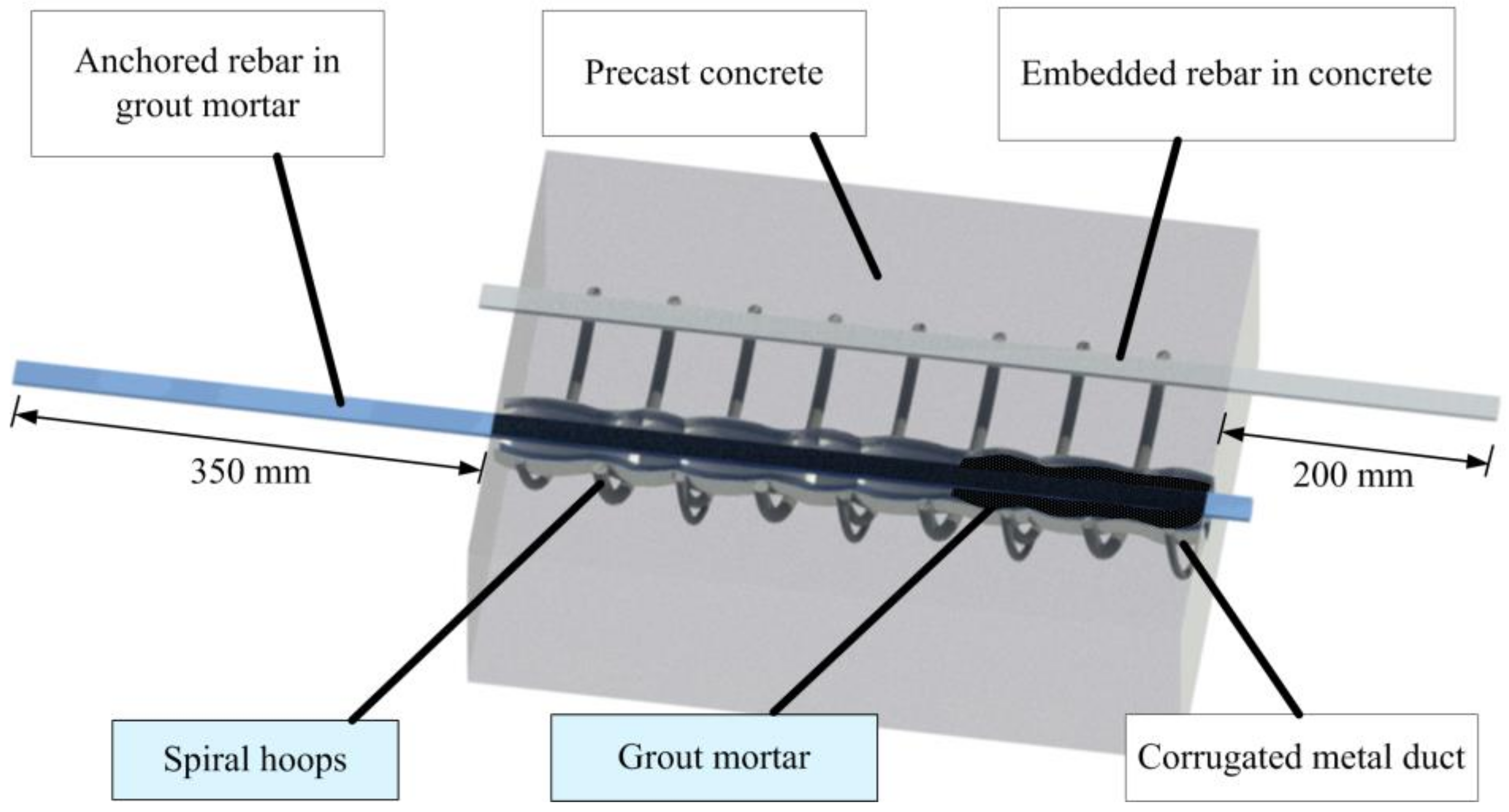
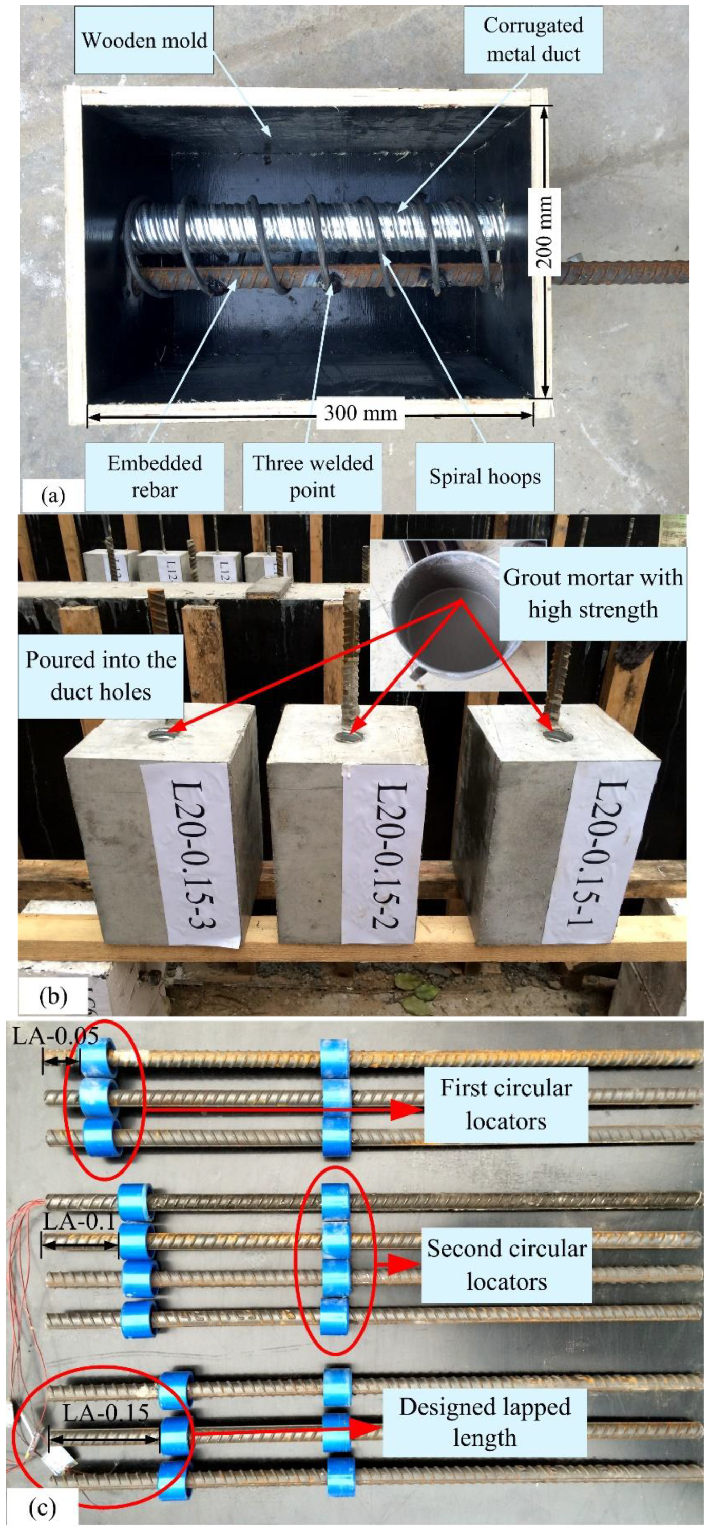
2.1. Design of Specimens

In this study, the dimension for the short-lapped-rebar splices was 200 mm × 200 mm × 300 mm, as shown in Figure 4. A corrugated metal duct with 300 mm in length, 40 mm in diameter, 0.2 mm in wall thickness, and 5 mm in wave height was utilized. The spiral hoops diameter was selected as 8 mm and three different diameters of rebar (i.e., 12 mm, 16 mm and 20 mm) were selected as the anchored rebar or the embedded rebar. The rebar at the anchorage end was 200 mm longer than the splices and the rebar at the loading end was 350 mm longer than the splices considering the length of the loading jack, as shown in Figure 3. The inner diameter and the spacing of the spiral hoops are 75 mm and 50 mm, respectively.

2.2. Material Properties

According to GB17671-1999 [17], the average compression strength of CGM-340 high-strength non-shrinkage grout after 28 days was 84.33 MPa, which is established from the compression testing of three specimens, as shown in Table 1. Similarly, the average compression strength of concrete from compression testing was 59.30 MPa according to GB17671-1999 [17], as shown in Table 2. Tensile testing was also performed to obtain the material property of rebar according to GB1499.2-2007 [18], as shown in Table 3. For example, the average yield strength and the ultimate strength of rebar with the diameter of 12 mm were 430.08 MPa and 574.43 MPa, respectively.

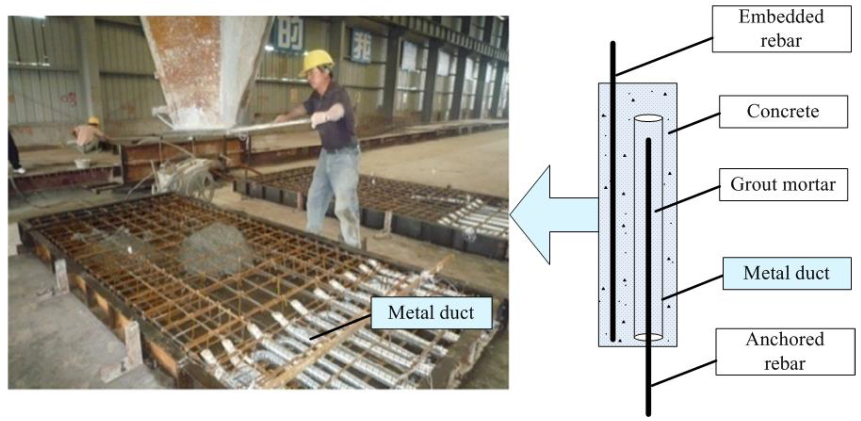
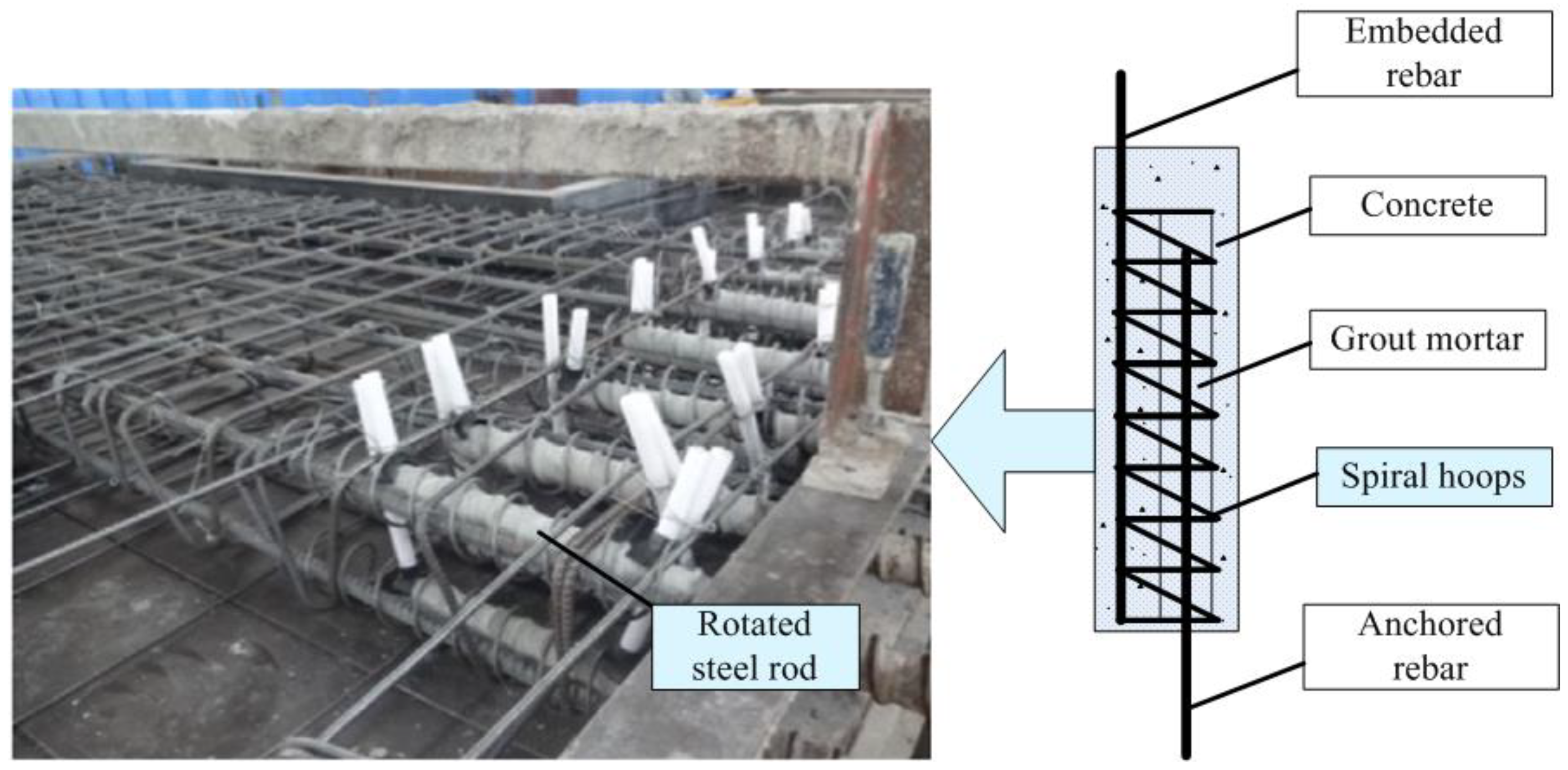
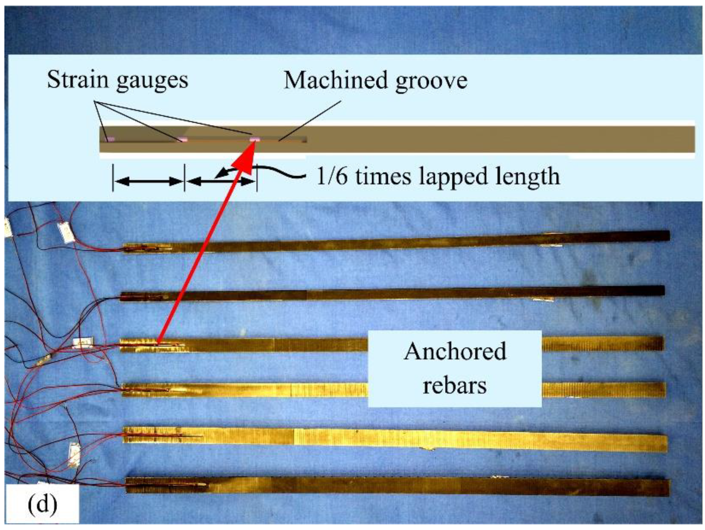
2.3. Precast Construction Process
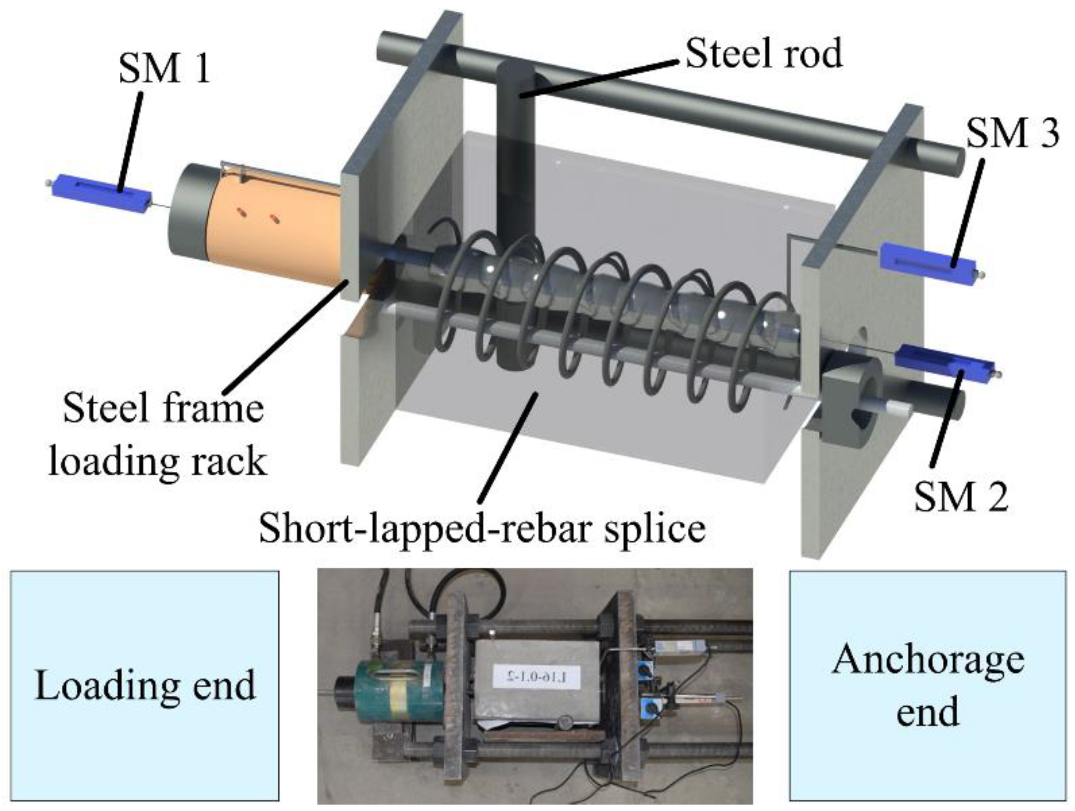
The precast construction process of the short-lapped-rebar splices can be divided into five steps: First, a unique wooden mold was made and the metal duct and the embedded rebar were fixed on the mold, as shown in Figure 4a. Then, the spiral hoops were welded on the embedded rebar. The concrete was then poured and the mold was kept for seven days. Figure 4b shows the specimen with the pre-set duct hole after removing the mold. After that, the anchored rebar with two circular plastic locators (Figure 4c) was installed in the duct holes. Note that the first circular locator was used to ensure the designed lapped length, and the second circular locator was used to fix the anchored rebar to the center of the duct. The high-strength grouted mortar was finally poured into the duct holes and cured for 28 days.

2.4. Testing Setup

To obtain the strain variation of rebar, six strain gauges were arranged at each 1/6 of the lapped length, as shown in Figure 4d. Three displacement meters (i.e., SM1, SM2, and SM3) (Jiangsu Donghua Testing Technology Co., Ltd, Taizhou, China) for obtaining the displacements at the loading end, the anchorage end, and the specimen were also arranged, as shown in Figure 5.
The tensile testing of the short-lapped-rebar splices was performed using a steel frame loading rack (Beijing Tianyijiashi International Technology Co., Ltd, Beijing, China) with the maximum bearing capacity of 1000 kN, as shown in Figure 5. The loading rate for the rebar with 12 mm in diameter was 6 kN/min and that for the rebar with the diameter of 16 mm and 20 mm was 10 kN/min. To avoid the eccentricity, two steel rods were added at both sides of the steel frame loading rack.

3. Test results and Discussion
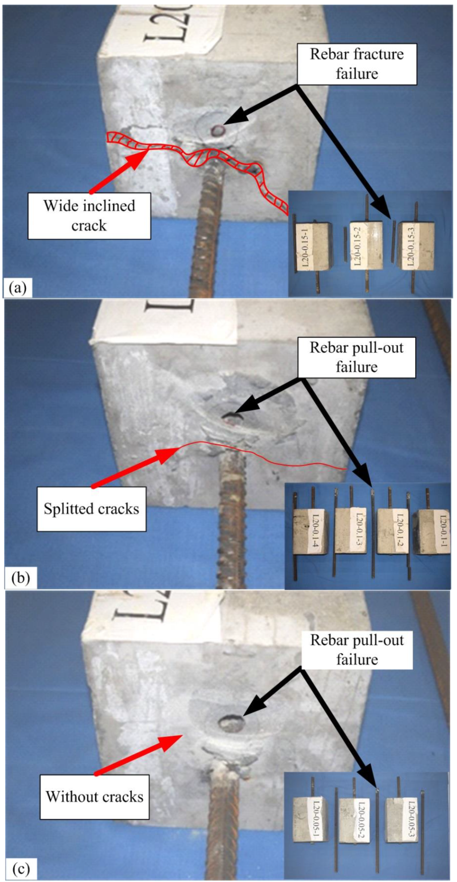
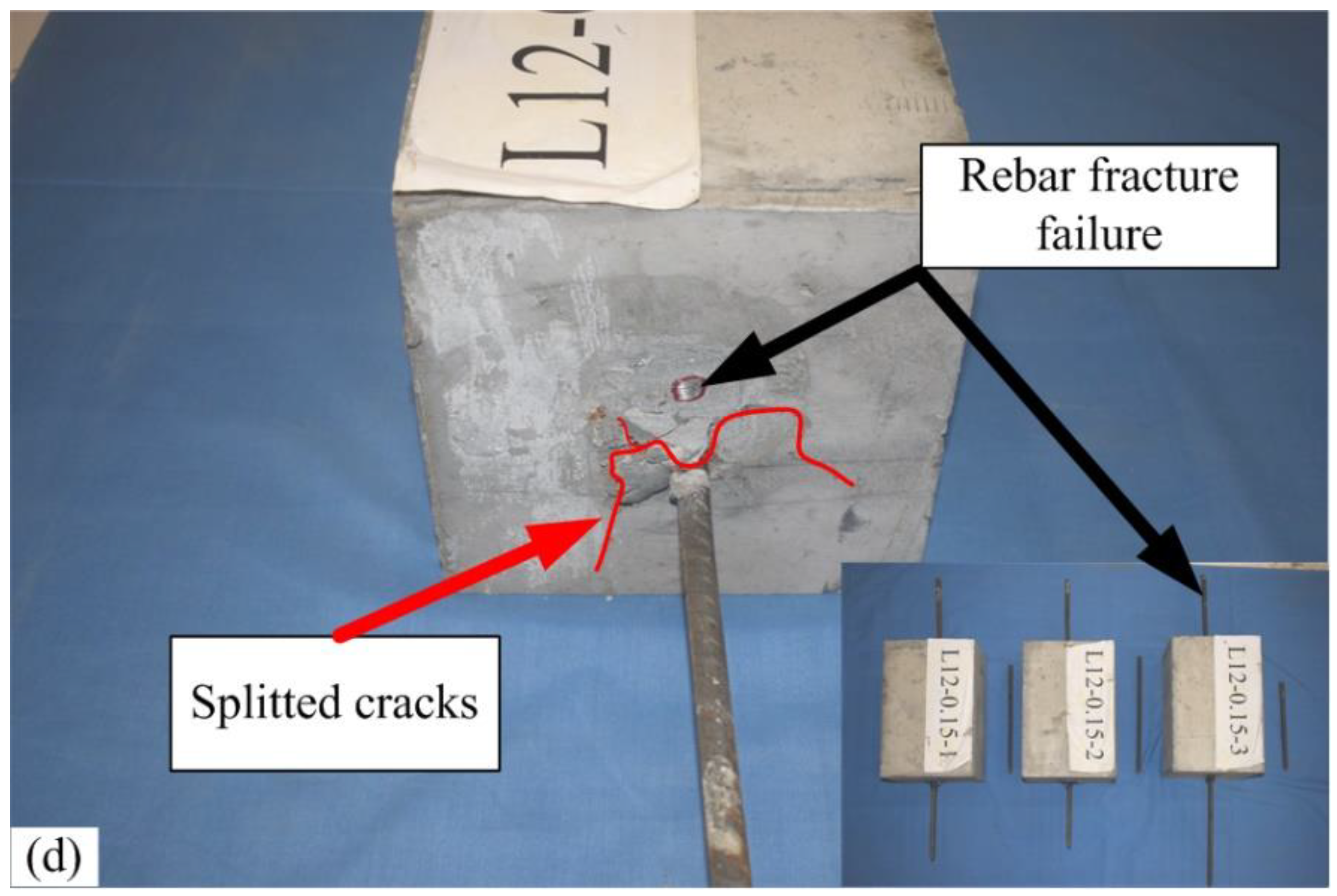
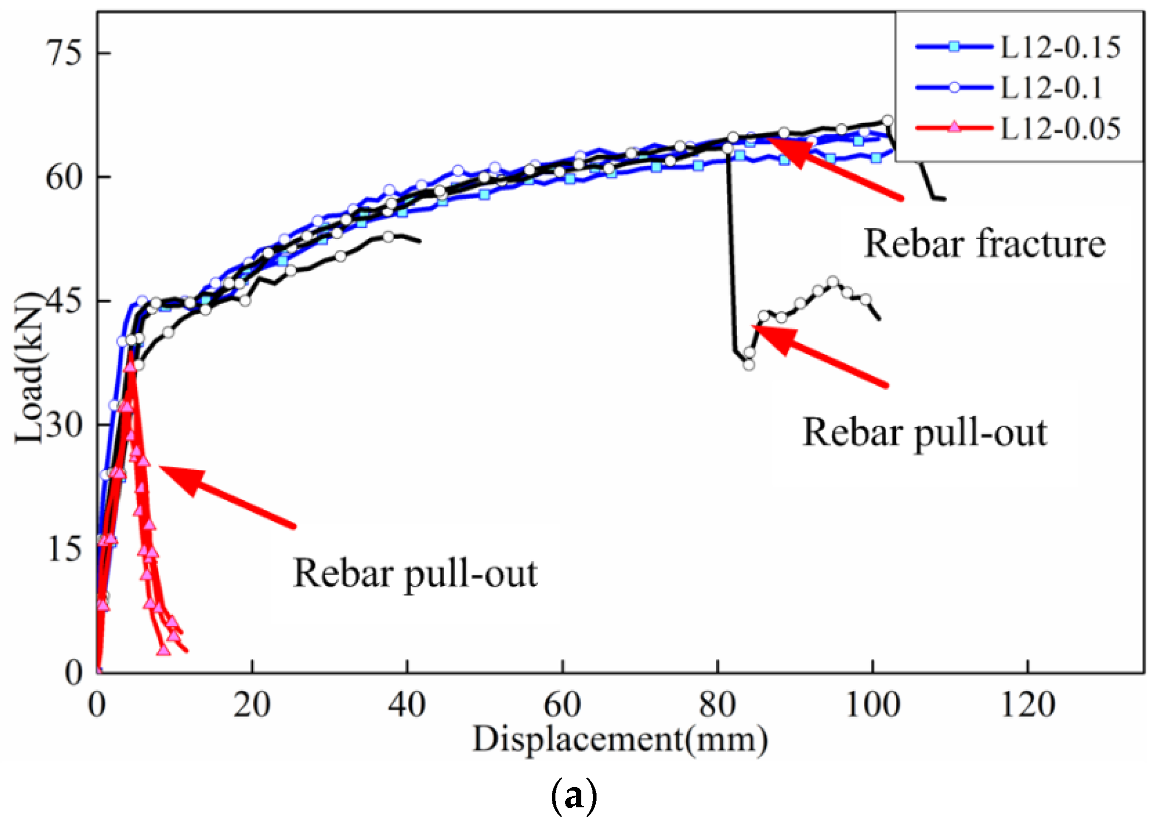
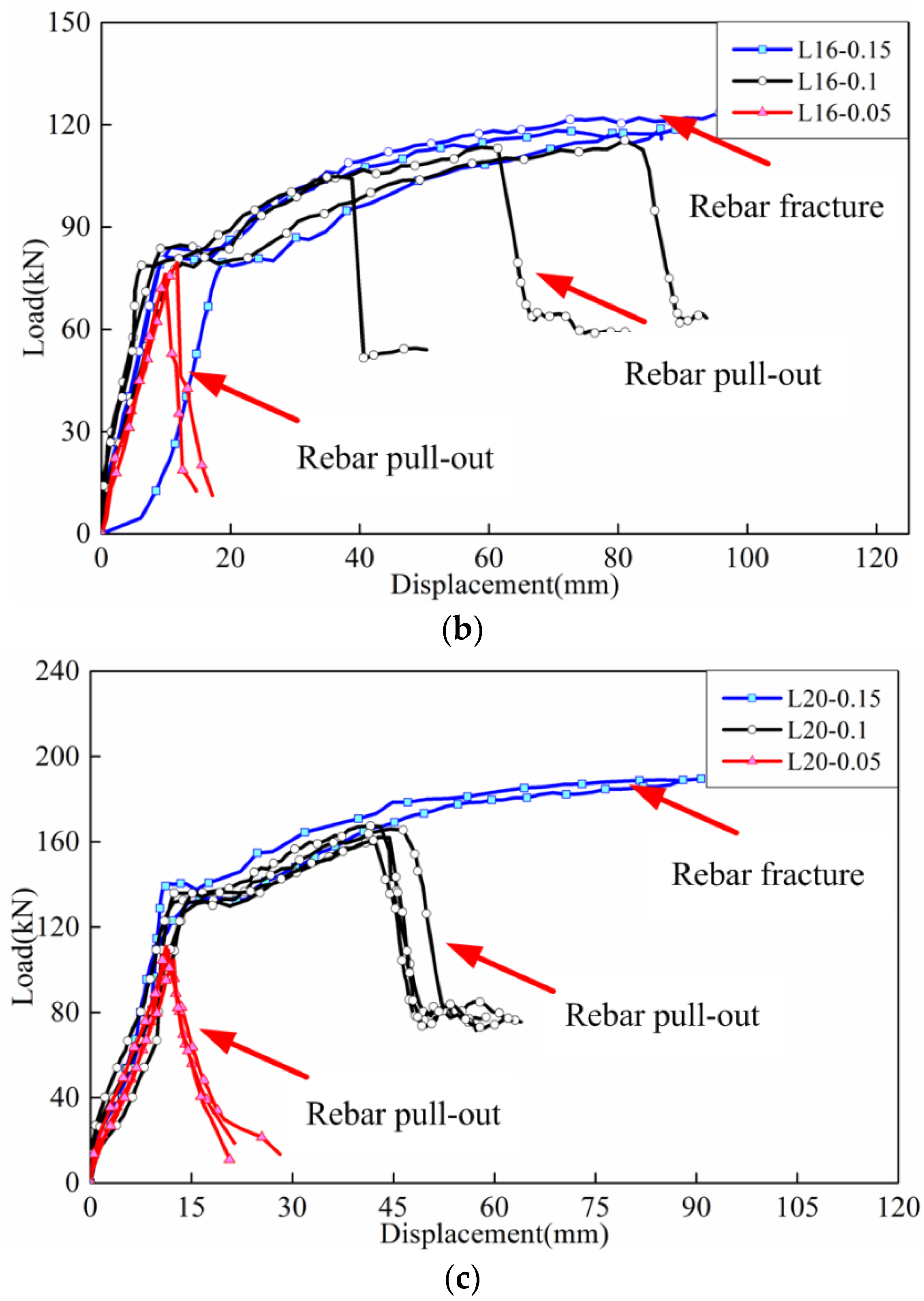
3.1. Failure Modes

As expected, two different failure modes, namely, the fracture of rebar and the pull-out failure of rebar, were found, as shown in Table 4.
For the specimen with 0.15 times of the suggested length in GB 50010–2010 shown in Table 4 [19] (LA-0.15), the bond strength between grout and rebar was strong enough to resist the tensile loading, and the failure mode for the fracture of rebar was shown, as shown in Figure 6a. Clearly, all anchored rebar fractured at the center of splices. In addition, a wide inclined crack appeared between the anchored rebar and embedded rebar at the anchorage end of the splice, as shown in Figure 6a. This may be attributed to the small eccentricity of tensile loading. For the specimens with 0.10 times and 0.05 times the suggested length in Table 4 (LA-0.10, LA-0.05), the bond strength between grout and rebar was not strong enough to resist the tensile loading, and the failure mode for the rebar pull-out failure was shown, as shown in Figure 6b,c.
In contrast, Specimen LA-0.1 or Specimen LA-0.05 shows the pull-out failure of rebar, as shown in Figure 6b,c. Clearly, the shear failure of grout mortar was shown. Note that spitted cracks were also found on the anchored rebar of Specimen LA-0.1.
As shown in Figure 6d, the rebar diameter had little effect on the failure mode in the short-lapped-rebar splices, but the development of cracks was influenced by the rebar diameter. For example, Specimen L12-0.15 shows smaller cracks than that of Specimen L20-0.15. This may be attributed to the decrease in area (diameter) and yielding forces of rebar.

3.2. Ultimate Strength

Figure 7 shows the load–displacement curves of the short-lapped-rebar splices under tensile loading. Clearly, Specimen L20-0.15 (Figure 7c) showed an obvious yielding stage and hardening stage and it had higher strength than Specimen L20-0.10 and L20-0.05. In contrast, the yielding stage was not exhibited for Specimen L20-0.05, and it fractured at an early stage due to the limited bond strength between grout and rebar. Table 4 lists the yield strength and the ultimate strength, including the ultimate bond strength of the short-lapped-rebar splices. Compared with the conventional splices without high strength grout [20] or transverse spiral hoops [21], the ultimate strength of the short-lapped-rebar splices was significantly improved.
As listed in Table 4, the effect of the rebar diameter on the ultimate strength of the short-lapped-rebar splices is not significant. For example, the ultimate strength of Specimen L20-0.15-1 is 1.12 times of that of Specimen L12-0.15-1 when the rebar diameter increases from 12 mm to 20 mm.

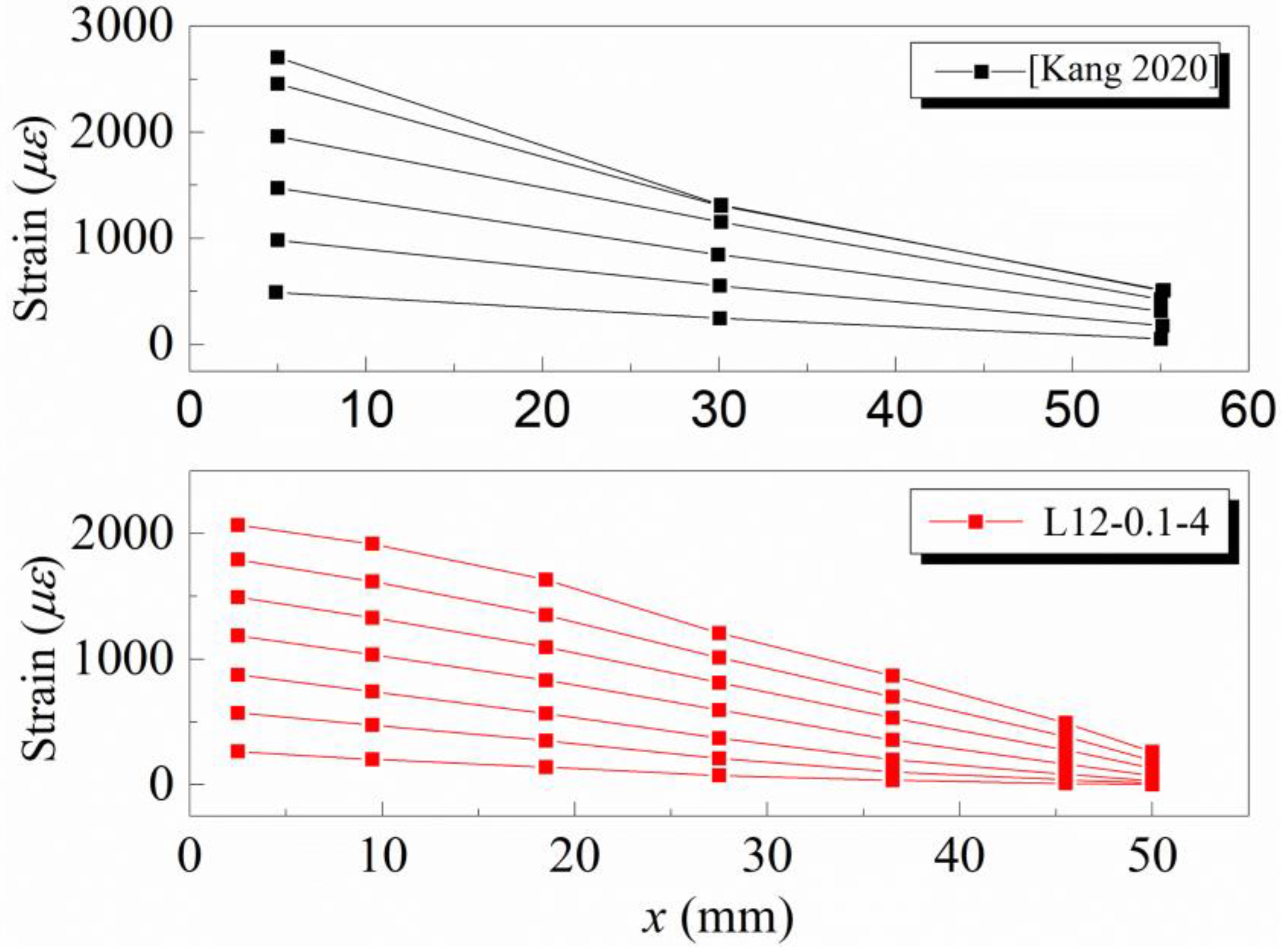
3.3. Strain Variation of Rebar

Strain variations in the anchored rebar along the longitudinal direction at different loading levels are depicted in Figure 8. Here, xi is the distance from the loading end to the anchorage end. Clearly, the strain of the anchored rebar increases from the loading end to the anchorage end, as shown in Figure 8. A similar phenomenon is also found in Kang’s test [22], as shown in Figure 8.
According to Xu’s method [23], the average bond stress τi between the grout mortar and the anchored rebar can be established from the strain of the anchored rebar. Figure 9 illustrates the distribution of the average bond stress τi along the longitudinal direction at different loading levels. Compared with the stress distribution of the anchored rebar in conventional specimens shown in Xu’s test [23], the stress of the anchored rebar in the short-lapped-rebar splices is distributed symmetrically along the longitudinal direction, as shown in Figure 9. In contrast, the stress of the anchored rebar in conventional specimens is relatively high at the anchorage end. In addition, the bond stress of the short-lapped-rebar splices is much higher than that of the conventional specimens shown in Xu’s test [23] and GB50010-2010 [19].

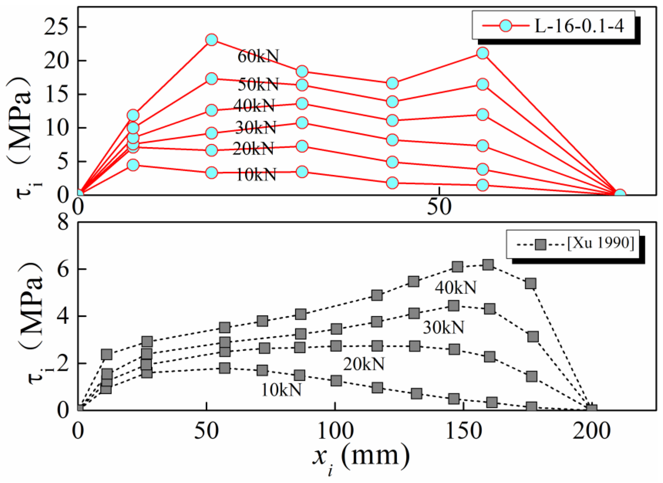
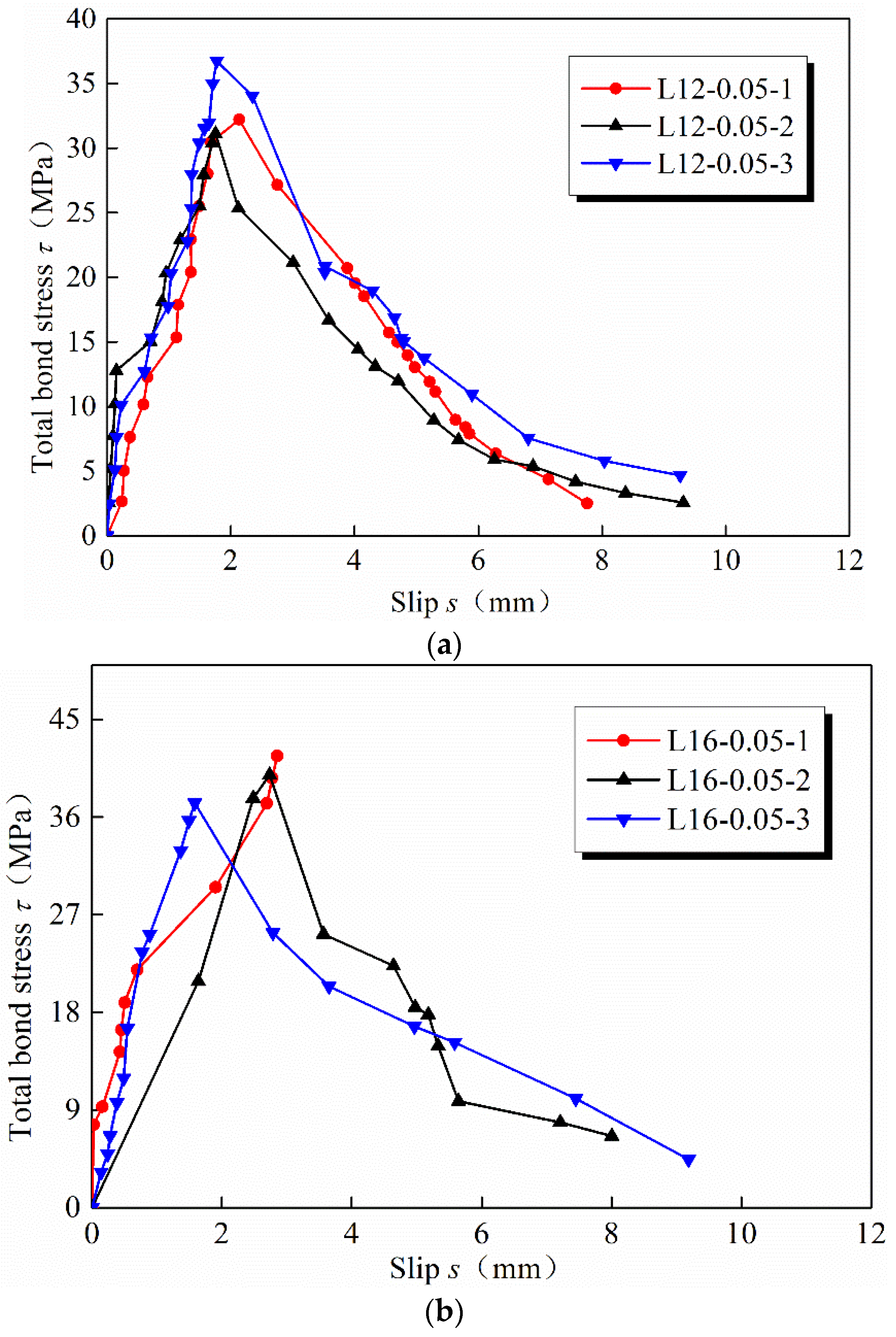
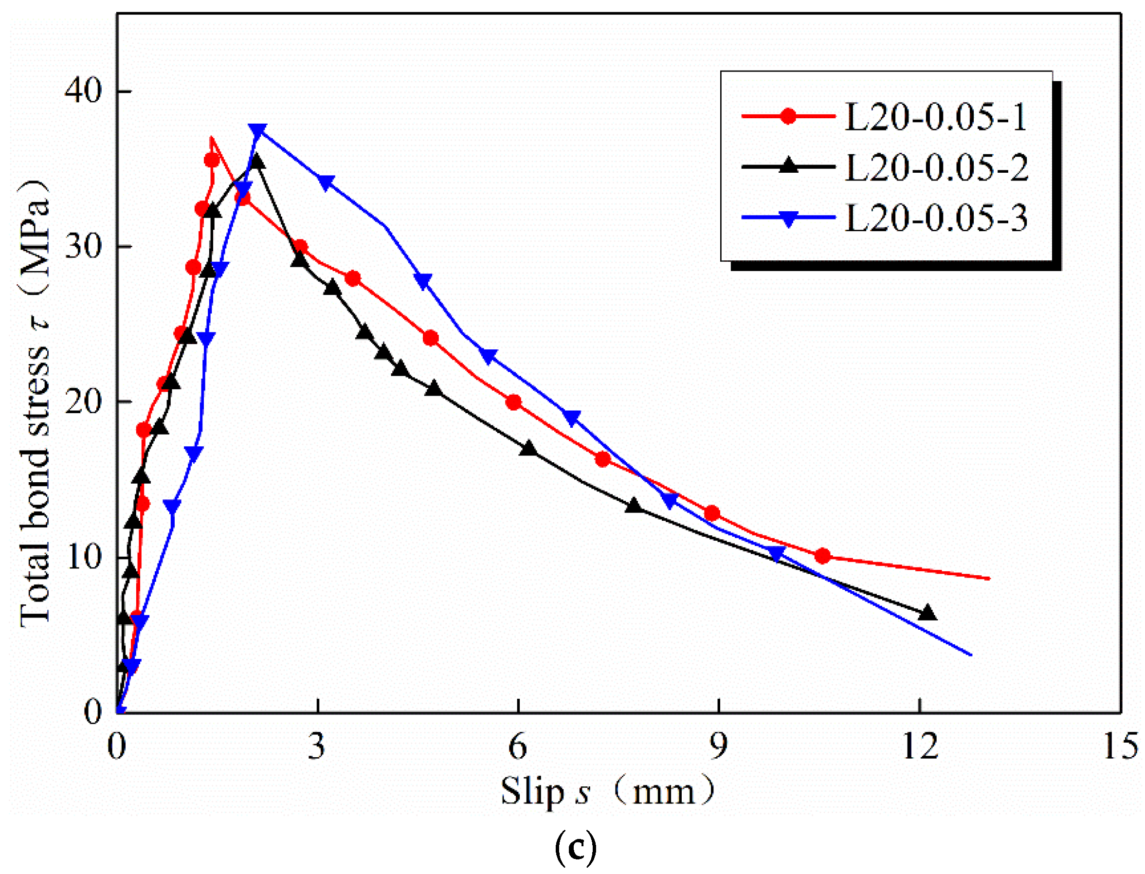
3.4. Bond Slip Behavior

On the basis of the values of SMs, the slip displacement s between the grout mortar and the anchored rebar can be obtained from Equation (1).
s = ( S S M 1 S S M 2 ) ( S S M 2 S S M 3 )
where SM1 is the displacement of the anchored rebar in the loading end, SM2 is the displacement of the anchored rebar in the anchorage end, and SM3 is the displacement of the short-lapped-rebar splices.
The total bond stress between the grout mortar and the anchored rebar is the sum of the bond stress τi from the loading end to the anchorage end, as shown below.
τ = P π d l l
where P is the axial load applied to the loading end of the anchored rebar, d is the diameter of the anchored rebar, and ll is the lapped length of the anchored rebar.
Figure 10 shows the relationships between the total bond stress τ and the slip displacement s. Clearly, the total bond stress increases linearly with the increase in the slip displacement. The maximum bond stress (the ultimate bond strength) reaches 35 MPa, which is approximately 1.4 times that in conventional specimens [23,24].

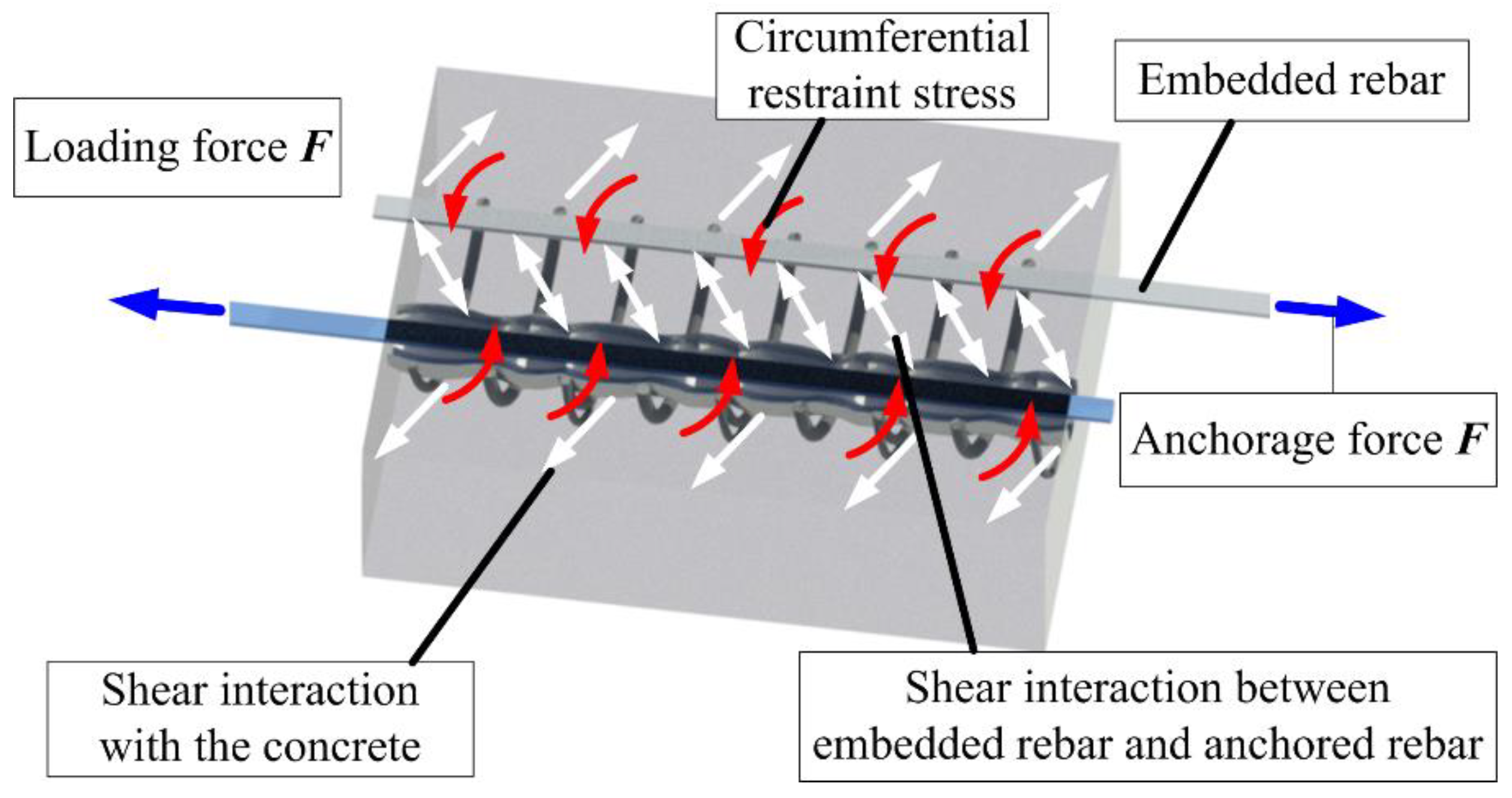
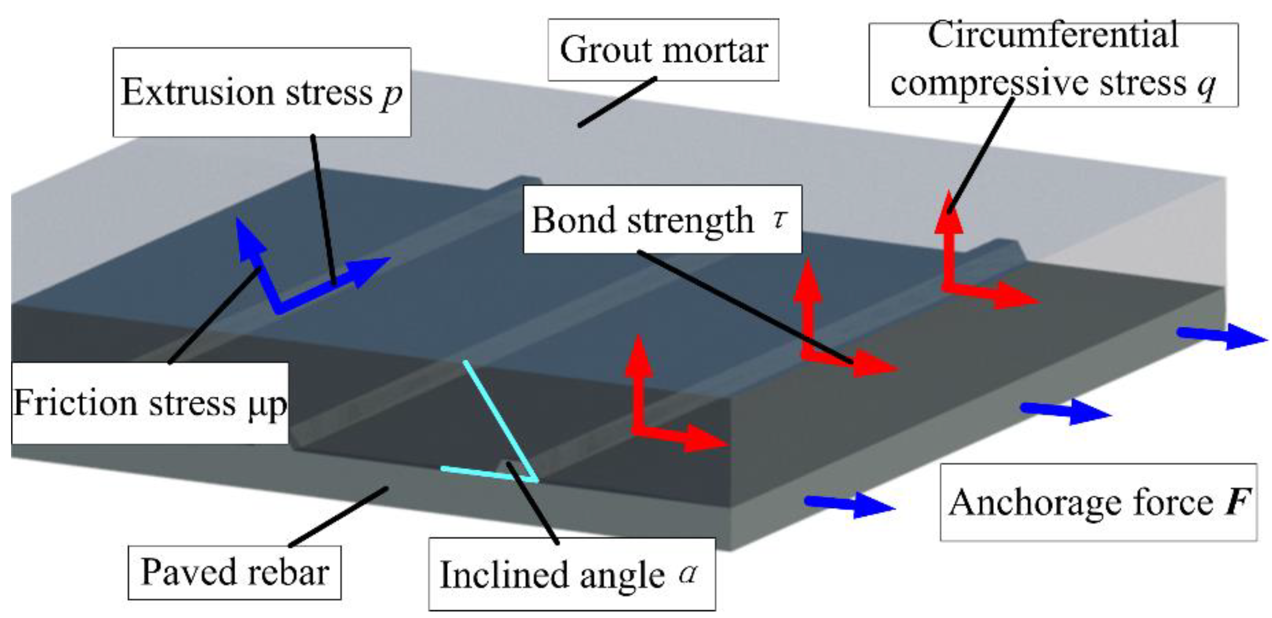
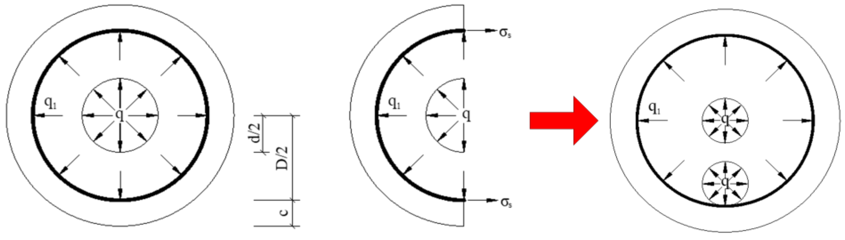
4. Models for the Ultimate Bond Strength
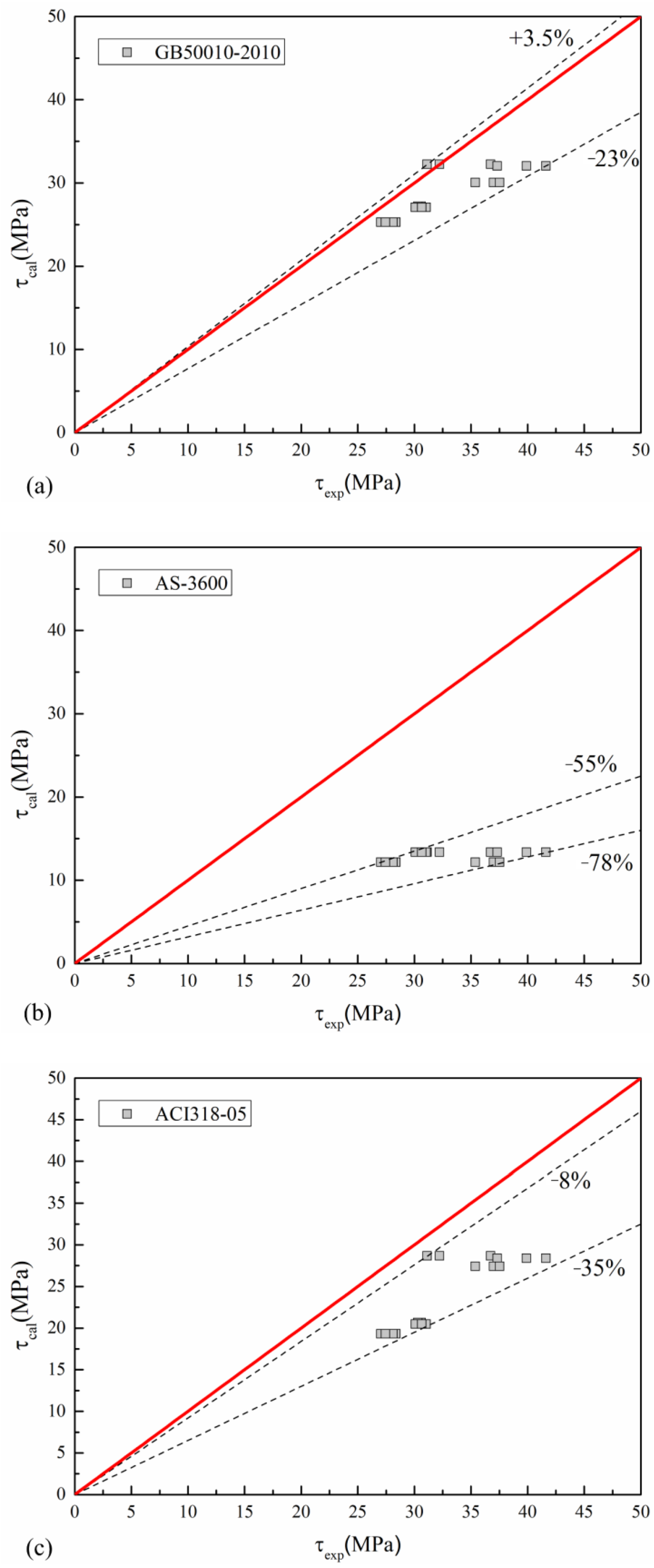
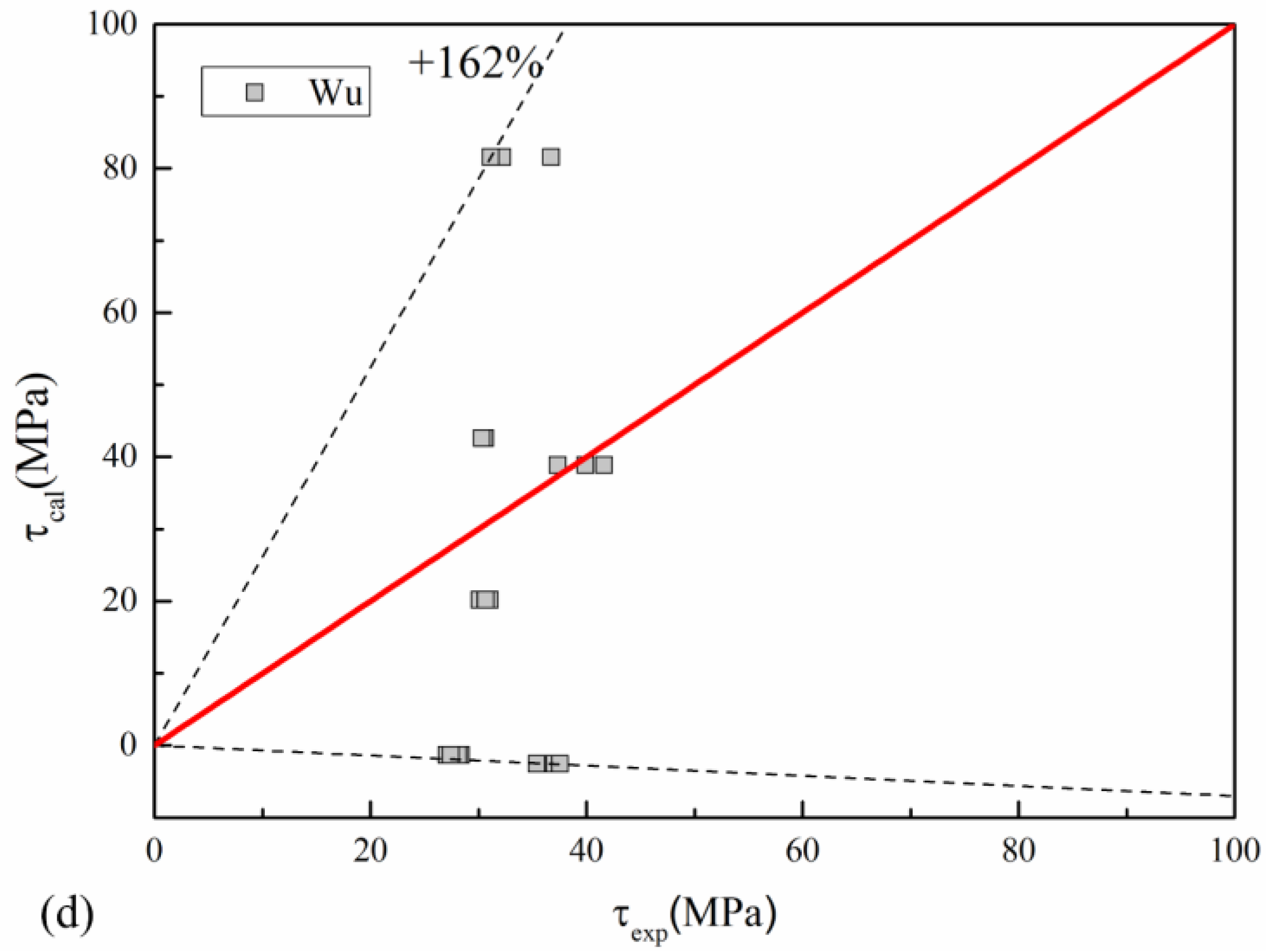
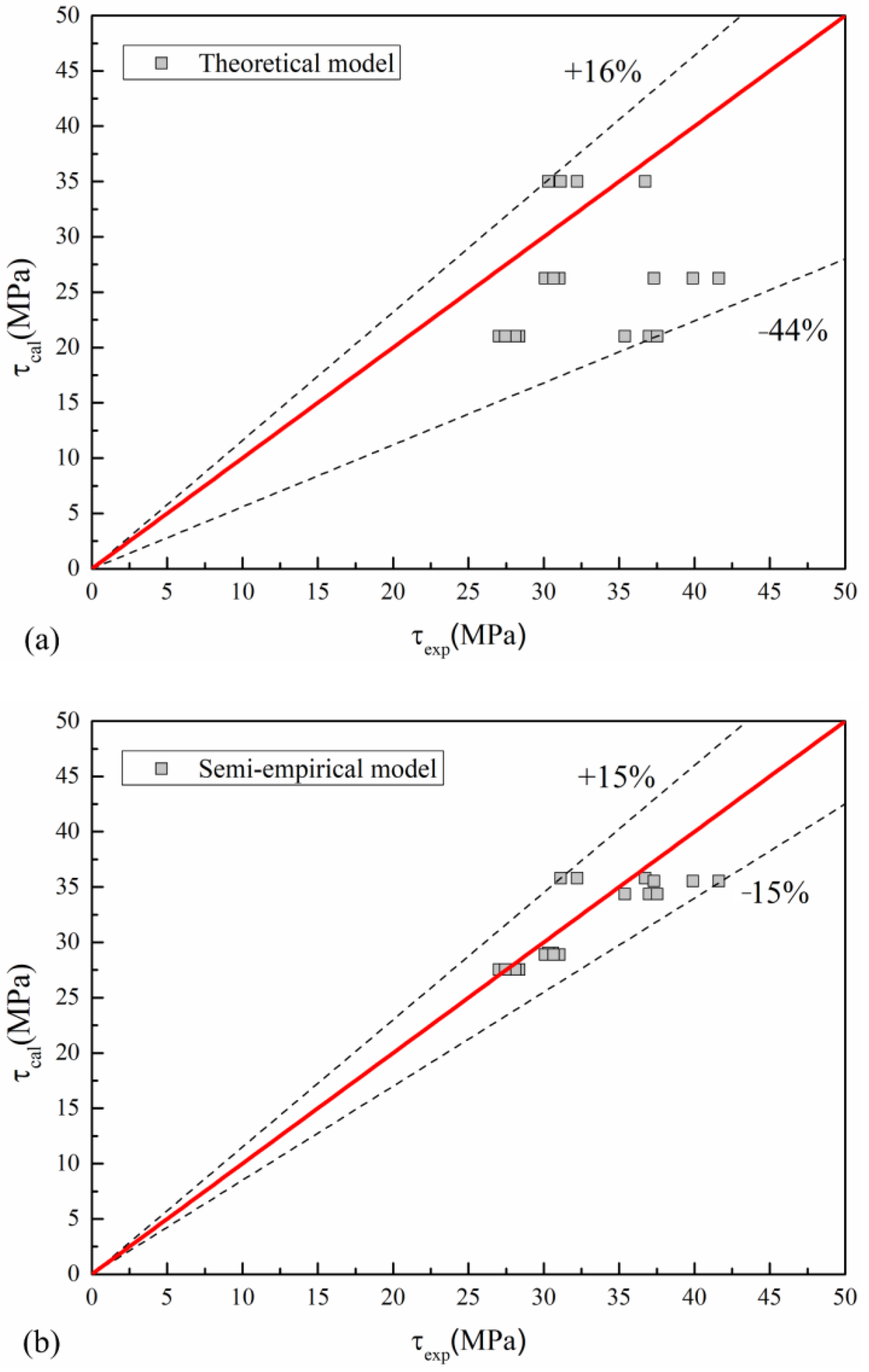
4.1. Current Models

Previously, variety formulas for the ultimate bond strength of anchoring or lapping rebar were provided in GB 50010-2010 [19], AS-3600 [25], ACI 318-05 [26], and Wu [27], as shown in Equations (3)–(6).
τ u = ( 0.82 + 0.9 d l a ) ( 1.6 + 0.7 c d + 20 ρ s v ) f t
τ u = 0.265 ( c d + 0.5 ) f u
τ u = 0.083 ( 1.2 + 3 c d + 50 d l a ) f u
τ u = ( 0.36 + 30.81 d l s ) ( 2.48 6.2 d D + 46.9 ρ s v ) f t
where τu is the ultimate bond strength, d is the rebar diameter, la is the anchorage length, ls is the lapped length, c is the concrete cover thickness, ρsv is the spiral hoop ratio, fu is the ultimate compressive strength of concrete or grout mortar, and ft is the ultimate tensile strength of concrete or grout mortar, which can be established from Equation (7) [28].
f t = 0.26 f u 2 / 3
The comparison of the ultimate bond strength between various models and test data is shown in Figure 11. As the high-strength grouted mortar and the spiral hoop effect is not considered in AS-3600 [25] and ACI 318-05 [26], the estimated values from these two specifications are much smaller than the tested values, and the maximum error reaches 20%. Wu’s model [27] shows obvious difference with the test data as his model is developed based on the experiment of the long-lapped-rebar splices. GB 50010-2010 [19] is a little underestimated as the maximum error reaches −23%. For predicting the behavior of the short-lapped-rebar splice, it is necessary to develop a more accurate model for the ultimate bond strength.

4.2. A Semi-Empirical Model for the Ultimate Bond Strength

Figure 12, Figure 13 and Figure 14 illustrate the mechanical mechanism of the short-lapped-rebar splice. Similar to conventional splices, the shear force is carried by the friction force, mechanical interlocking force, and chemical cemented force. However, in conventional splices, cracks easily appear on the concrete near the zone of the connection. In the short-lapped-rebar splice, the concrete is constrained by the spiral hoops, which can effectively limit the development of cracks and increase the ultimate bond strength. As illustrated in Figure 12, the shear force is transferred from the anchored rebar to the embedded rebar through grout, metal duct, and concrete.
Figure 13 illustrates the stress distribution of the interaction surface between the anchored rebar and the grout mortar along the longitudinal direction. Under the action of external anchorage force F, the interaction surface between the rebar rib and grout mortar is subjected to extrusion stress p and friction stress μp. On the basis of equivalent conditions, the stress in the horizontal and circumferential direction can be obtained, as shown in Equation (8).
τ = p sin α + μ p cos α q = p cos α μ p sin α
where τ is the bond strength between the rebar and grout mortar; q is the circumferential compressive stress; p is the extrusion stress between the rebar and the grout mortar; μ is the friction coefficient between concrete and rebar, which is 0.3; and α is the inclined angle between rebar rib and grout mortar, which is 45 degrees [19,29].
The stress distributed on the cross section of the short-lapped-rebar splice is shown in Figure 14. Note that the assumption that the stress and cracks only spread to the outer bound of the spiral hoop is made. The constraining effect of the spiral hoop can be considered as a thick-walled cylinder with two rebar subjected to uniformly distributed stress, as shown in Figure 14. Based on the thick-walled cylinder theory [29], the circumferential tensile stress of the grout mortar or concrete at a certain point can be obtained from Equation (9).
q π d = 1 2 q 1 π D σ θ = q 1 ( D / 2 ) 2 ( c + D / 2 ) 2 ( D / 2 ) 2 [ 1 + ( c + D / 2 ) 2 r 2 ]
where q1 is the compressive stress of the grout mortar, c is the protective layer of concrete, D is the inner diameter of the spiral hoop, and r is the distance from the certain point to the center of specimen, σθ is the circumferential tensile stress at the certain position.
Similar with Xu’s method [30], a constraint coefficient, β, is utilized to consider the constraint effect of the spiral hoop, as shown below.
σ θ r = D / 2 = β f t
where β is the constraint coefficient of the spiral hoop, and it is suggested to be 1.2, according to Xu’s test [30].
On the basis of Equations (7)–(10), the ultimate bond strength can be obtained, as shown below.
τ u = 1.12 D d ( c + D / 2 ) 2 ( D / 2 ) 2 ( c + D / 2 ) 2 + ( D / 2 ) 2 f t
As shown in Figure 15 and Table 5, there is a significant error between theoretical and tested values. The reason for that is that the influences of the lapped length, the rebar diameter, and the protective layer are not fully considered. As a result, another coefficient for considering the effects of the lapped length, the rebar diameter, and the protective layer is proposed, as shown below.
τ u = η τ u
where τu is the ultimate bond strength, and η is the affecting coefficient considering the effects of the lapped length, the rebar diameter, and the protective layer.
From the results of the test, the affecting coefficient has good relations with the rebar diameter, the ratio of the rebar diameter to the lapped length, and the ratio of the protective layer to the rebar diameter, as shown in Equation (13).
η = ( 0.08 d l l + 0.007 c d + 0.02 ) d   c d 5.0 ( 0.08 d l l + 0.055 ) d     c d > 5.0
where τu is the ultimate bond strength, d is the anchored rebar diameter, ll is the lap length, and c is the concrete cover thickness.
Based on Equations (7)–(13), the ultimate bond strength of the short-lapped-rebar splice can be obtained. The comparison of the ultimate bond strength between the proposed models and the tested values is shown in Figure 15 and Table 5. The average error estimated from the proposed model is only 4.49%, and the maximum error varies from −15% to 15%. Clearly, the proposed model is more accurate than the existing models.

5. Conclusions

In this study, a new type of connection (the short-lapped-rebar splices) in precast concrete structure was developed, and the failure modes, strain distribution, bond slip behavior, and bond strength of the connection were experimentally investigated. A semi-empirical model was proposed to predict the ultimate bond strength of the short-lapped-rebar splices. The following conclusions are made:
(1) Two different types of failure modes for the short-lapped-rebar splices, namely, the fracture of rebar and the pull-out failure of rebar, are found.
(2) The short-lapped-rebar splices have higher ultimate strength or ultimate bond strength than that of the conventional lapped splices.
(3) The stress of the anchored rebar in the short-lapped-rebar splices is distributed symmetrically along the longitudinal direction, and the maximum bond stress is approximately twice that of the conventional specimens.
(4) A semi-empirical model considering the effect of the spiral hoop is developed to predict the ultimate bond strength of the short-lapped-rebar splices, which shows good agreement with test data.
Note that the cyclic behavior of the short-lapped-rebar splices and structural reliability of the short-lapped-rebar splices are not included in this study; the determination of the lapped length of the rebar should be further studied before the design of the short-lapped-rebar splices.

Author Contributions

Conceptualization, Q.L. and X.L.; methodology, Q.L.; validation, Q.L., X.L. and R.C.; formal analysis, Q.L.; investigation, Q.L.; resources, X.L.; data curation, R.C.; writing—original draft preparation, Q.L.; writing—review and editing, Z.K.; visualization, T.X.; supervision, Z.K.; project administration, Q.L.; funding acquisition, Q.L. All authors have read and agreed to the published version of the manuscript.

Funding

This research was funded by (1) [Anhui University of Technology Foundation] grant number [QZ202015]; (2) [National Natural Science Foundation of China] grant number [52078042].

Data Availability Statement

The data presented in this study are available upon request from the corresponding author.

Acknowledgments

All the authors are very grateful to the anonymous reviewers and editors for their careful review and critical comments.

Conflicts of Interest

The authors declare no conflict of interest.

References

  1. Tazarv, M.; Shrestha, G.; Saiidi, M.S. State-of-the-art review and design of grouted duct connections for precast bridge columns. Structures 2021, 30, 895–909. [Google Scholar] [CrossRef]
  2. Zhi, Q.; Kang, L.; Jia, L.; Xiong, J.; Guo, Z. Seismic performance of precast shear walls prestressed via post-tensioned high strength bars placed inside grouted corrugated pipes. Eng. Struct. 2021, 237, 112153. [Google Scholar] [CrossRef]
  3. Raynor, D.J.; Lehman, D.E.; Stanton, J.F. Bond-Slip Response of Reinforcing Bars Grouted in Ducts. ACI Struct. J. 2002, 99, 568–576. [Google Scholar]
  4. Matsumoto, E.E.; Waggoner, M.C.; Kreger, M.E.; Vogel, J.; Wolf, L. Development of a precast concrete bent-cap system. PCI J. 2008, 53, 74–99. [Google Scholar] [CrossRef]
  5. Brenes, F.J. Anchorage of Grouted Vertical Duct Connections for Precast Bent Caps. Ph.D Thesis, University of Texas, Austin, TX, USA, 2005. [Google Scholar]
  6. Steuck, K.P.; Eberhard, M.O.; Stanton, J.F. Anchorage of Large-Diameter Reinforcing Bars in Ducts. ACI Struct. J. 2009, 106, 506–513. [Google Scholar] [CrossRef]
  7. Galvis, F.A.; Correal, J.F. Anchorage of Bundled Bars Grouted in Ducts. ACI Struct. J. 2018, 115, 415–424. [Google Scholar] [CrossRef]
  8. Zhi, Q.; Xiong, J.; Yang, W.; Liu, S. Experimental Study on Shear Transfer Performance of Uncracked Monolithic Steel Fiber Concrete. KSCE J. Civ. Eng. 2022, 26, 5210–5221. [Google Scholar] [CrossRef]
  9. Seifi, P.; Henry, R.S.; Ingham, J.M. In-plane cyclic testing of precast concrete wall panels with grouted metal duct base connections. Eng. Struct. 2019, 184, 85–98. [Google Scholar] [CrossRef]
  10. Tazarv, M.; Saiidi, M.S. UHPC-filled duct connections for accelerated bridge construction of RC columns in high seismic zones. Eng. Struct. 2015, 99, 413–422. [Google Scholar] [CrossRef]
  11. Hofer, L.; Zanini, M.A.; Faleschini, F.; Toska, K.; Pellegrino, C. Seismic behavior of precast reinforced concrete column-to-foundation grouted duct connections. Bull. Earthq. Eng. 2021, 19, 5191–5218. [Google Scholar] [CrossRef]
  12. Ma, C.; Jiang, H.; Wang, Z. Experimental investigation of precast RC interior beam-column-slab joints with grouted spiral-confined lap connection. Eng. Struct. 2019, 196, 109317. [Google Scholar] [CrossRef]
  13. Zhang, H.S. Experimental Study on Plug-in Filling Hole for Lap-Joint of Steel Bar of PC Concrete Structure. Ph.D. Thesis, Harbin Institute of Technology, Harbin, China, 2009. (In Chinese). [Google Scholar]
  14. Gu, Q.; Wu, R.; Ren, J.; Tan, Y.; Tian, S.; Wen, S. Effect of position of non-contact lap splices on in-plane force transmission performance of horizontal joints in precast concrete double-face superposed shear wall structures. J. Build. Eng. 2022, 51, 104197. [Google Scholar] [CrossRef]
  15. Gu, Q.; Dong, G.; Ke, Y.; Tian, S.; Wen, S.; Tan, Y.; Gao, X. Seismic behavior of precast double-face superposed shear walls with horizontal joints and lap spliced vertical reinforcement. Struct. Concr. 2020, 21, 1973–1988. [Google Scholar] [CrossRef]
  16. Jiang, J.; Luo, J.; Xue, W.; Hu, X.; Qin, D. Seismic performance of precast concrete double skin shear walls with different vertical connection types. Eng. Struct. 2021, 245, 112911. [Google Scholar] [CrossRef]
  17. GB17671-1999; Method of Testing Cements-Determination of Strength. Chinese Code: Beijing, China, 1999. (In Chinese)
  18. GB1499 2-2007; Steel for the Reinforcement of Concrete—Part 2: Hot rolled ribbed bars. Chinese Code: Beijing, China, 2007. (In Chinese)
  19. GB50010-2010; Code for Design of Concrete Structures (English Version). China Architecture & Building Press: Beijing, China, 2009.
  20. Gu, Q.; Dong, G.; Wang, X.; Jiang, H.; Peng, S. Research on pseudo-static cyclic tests of precast concrete shear walls with vertical rebar lapping in grout-filled constrained hole. Eng. Struct. 2019, 189, 396–410. [Google Scholar] [CrossRef]
  21. Ma, J.; Zhu, J.; Bai, G.; Zheng, W. Experimental study on anchoring performance of steel bar-corrugated pipe grouted connection. Structures 2021, 34, 1834–1842. [Google Scholar] [CrossRef]
  22. Kang, S.B.; Wang, S.; Long, X.; Wang, D.-D.; Wang, C.-Y. Investigation of dynamic bond-slip behavior of reinforcing bars in concrete. Constr. Build. Mater. 2020, 262, 120824. [Google Scholar] [CrossRef]
  23. Xu, Y.L. Experimental Study of Anchorage Properties for Deformed Bars in Concrete. Ph.D. Thesis, Tsinghua University, Beijing, China, 1990. (In Chinese). [Google Scholar]
  24. Elsayed, M.; Nehdi, M.L. Experimental and analytical study on grouted duct connections in precast concrete construction. Mater. Struct. 2017, 50, 198. [Google Scholar] [CrossRef]
  25. AS3600-2009; Concrete Structures. Standards Australia: Sydney, Australia, 2009.
  26. ACI 318-05; Building Code Requirements for Structural Concrete and Commentary. ACI Committee 318. Structural Building Code. American Concrete Institute: Farmington Hills, MI, USA, 2005.
  27. Wu, Z. Study on Mechanical Properties of Prefabricated Hole with Embedded Metal Bellows for Constraint Grout-Filled Lap Connection of Steel Bar. Master’s Dissertation, Xi’an University of Architecture and Technology, Xi’an, China, 2019. (In Chinese). [Google Scholar]
  28. Guo, Z.H.; Shi, X.D. Reinforced Concrete Theory and Analyse; Tsinghua University Press: Beijing, China, 2003. (In Chinese) [Google Scholar]
  29. Wu, T.; Liu, Q.W.; Cheng, R.; Liu, X. Experimental study and stress analysis of mechanical performance of grouted sleeve splice. Eng. Mech. 2017, 34, 68–75. (In Chinese) [Google Scholar]
  30. Xu, F.; Wang, K.; Wang, S.; Li, W.; Liu, W.; Du, D. Experimental bond behavior of deformed rebars in half-grouted sleeve connections with insufficient grouting defect. Constr. Build. Mater. 2018, 185, 264–274. [Google Scholar] [CrossRef]
Figure 1. Corrugated metal duct connections [8].
Metals 13 00530 g001
Figure 2. Lapped connection [12].
Metals 13 00530 g002
Figure 3. The short-lapped-rebar splices.
Metals 13 00530 g003
Figure 4. Precast construction process. (a) Mold with spiral hoops, rebar, and duct (b) Grout pouring (c) Anchored rebar with the locators (d) Arrangement of strain gauges.
Metals 13 00530 g004aMetals 13 00530 g004b
Figure 5. Testing schematic.
Metals 13 00530 g005
Figure 6. Failure modes of the short-lapped-rebar splices (a) Rebar fracture failure (L20-0.15) (b) Rebar pull-out failure (L20-0.1) (c) Rebar pull-out failure (L20-0.05) (d) Rebar fracture failure (L12-0.15).
Metals 13 00530 g006aMetals 13 00530 g006b
Figure 7. Load–displacement curves. (a) L12 (b) L16 (c) L20.
Metals 13 00530 g007aMetals 13 00530 g007b
Figure 8. Strain variations of xi–average strain at different loading levels [22].
Metals 13 00530 g008
Figure 9. Strain distributions of xiτi under different loading levels [23].
Metals 13 00530 g009
Figure 10. Bond and slip relationships in Specimens. (a) L12-0.05 (b) L16-0.05 (c) L20-0.05.
Metals 13 00530 g010aMetals 13 00530 g010b
Figure 11. Comparison of ultimate bond strength between various models and test data. (a) GB50010-2010 [19] (b) AS-3600 [25] (c) ACI 318-05 [26] (d) Wu [27].
Metals 13 00530 g011aMetals 13 00530 g011b
Figure 12. Bond mechanism of the short-lapped-rebar splices.
Metals 13 00530 g012
Figure 13. Stress distribution of the interaction surface.
Metals 13 00530 g013
Figure 14. Stress distributed on the cross section.
Metals 13 00530 g014
Figure 15. Comparison of the ultimate bond strength between estimated values and test data (a) Theoretical model (b) Semi-empirical model.
Metals 13 00530 g015
Table 1. Compressive strength of high-strength grouted mortar.
NumberCompressive Strength (MPa)Average Compressive Strength (MPa)
179.6984.33
289.06
384.25
Table 2. Compressive strength of concrete.
NumberCompressive Strength (MPa)Average Compressive Strength (MPa)
157.2859.30
260.24
360.38
Table 3. Mechanical properties of rebar.
d/mmYield Strength (MPa)Average Yield Strength (MPa)Ultimate Strength (MPa)Average Ultimate Strength (MPa)Young’s Modulus E (×105)
12447.99430.08598.03574.431.90
423.09570.15
419.16555.11
16441.22435.58593.57590.291.98
434.96590.17
430.56587.15
20449.83448.29594.62594.802.07
451.25597.45
443.79592.34
Table 4. Experimental results.
Specimen LA-B-CFailure ModeYield Strength (MPa)Ultimate Strength or Ultimate Bond Strength (MPa)
L12-0.15-1Rebar fracture396.41558.83
L12-0.15-2Rebar fracture395.52571.48
L12-0.15-3Rebar fracture398.35579.45
L16-0.15-1Rebar fracture394.85591.41
L16-0.15-2Rebar fracture400.08590.42
L16-0.15-3Rebar fracture413.91614.45
L20-0.15-1Rebar fracture446.50601.24
L20-0.15-2Rebar fracture--
L20-0.15-3Rebar fracture425.57602.01
L12-0.10-2Rebar fracture396.14591.21
L12-0.10-4Rebar fracture378.27467.53
L16-0.10-4Rebar fracture398.64521.55
L12-0.10-1Rebar pull-out400.1230.61
L12-0.10-3Rebar pull-out399.0630.3
L16-0.10-1Rebar pull-out406.5031.04
L16-0.10-2Rebar pull-out419.0930.09
L16-0.10-3Rebar pull-out403.4130.64
L20-0.10-1Rebar pull-out434.7828.37
L20-0.10-2Rebar pull-out421.9127.04
L20-0.10-3Rebar pull-out422.1028.12
L20-0.10-4Rebar pull-out433.6627.45
L12-0.05-1Rebar pull-out-32.21
L12-0.05-2Rebar pull-out-31.13
L12-0.05-3Rebar pull-out-36.73
L16-0.05-1Rebar pull-out-41.62
L16-0.05-2Rebar pull-out-39.89
L16-0.05-3Rebar pull-out-37.31
L20-0.05-1Rebar pull-out-37.00
L20-0.05-2Rebar pull-out-35.38
L20-0.05-3Rebar pull-out-37.54
Note: L represents the short-lapped-rebar splices, A represents the diameter of rebar, B represents the ratio of the length of the lapped-rebar splices to the suggested length of splices (550 mm for rebar with 12 mm diameter, 750 mm for rebar with 16 mm diameter, and 940 mm for rebar with 20 mm diameter) in GB 50010-2010 [19], C represents the number of specimens (i.e., 1, 2, 3, and 4) in each group, and 4 represents the specimens with strain gauges in machined grooves, as shown in Figure 4d.
Table 5. Comparison of the ultimate bond strength between theoretical and semi-empirical values and test data.
Specimenτexp (MPa)fcu (MPa)ll (mm)d (mm)c/dτu(MPa)τu(MPa)Error (%)
L12-0.10-130.6184.335512535.00 30.43 0.59
L12-0.10-330.384.335512535.00 30.43 0.42
L12-0.05-132.2184.332812535.00 37.50 14.10
L12-0.05-231.1384.332812535.00 37.50 16.98
L12-0.05-336.7384.332812535.00 37.50 2.05
L16-0.10-131.0484.337516526.25 30.27 2.55
L16-0.10-230.0984.337516526.25 30.27 0.58
L16-0.10-330.6484.337516526.25 30.27 1.23
L16-0.05-141.6284.333816526.25 37.25 11.74
L16-0.05-239.8984.333816526.25 37.25 7.09
L16-0.05-337.3184.333816526.25 37.25 0.17
L20-0.10-128.3784.3394204.521.00 28.78 1.42
L20-0.10-227.0484.3394204.521.00 28.78 6.04
L20-0.10-328.1284.3394204.521.00 28.78 2.28
L20-0.10-427.4584.3394204.521.00 28.78 4.61
L20-0.05-13784.3347204.521.00 35.93 2.98
L20-0.05-235.3884.3347204.521.00 35.93 1.52
L20-0.05-337.5484.3347204.521.00 35.93 4.48
Note: τexp represents the values of tested data, τu represents the values of theoretical values, τurepresents the values of semi-empirical model.
Disclaimer/Publisher’s Note: The statements, opinions and data contained in all publications are solely those of the individual author(s) and contributor(s) and not of MDPI and/or the editor(s). MDPI and/or the editor(s) disclaim responsibility for any injury to people or property resulting from any ideas, methods, instructions or products referred to in the content.

