Communication

Three-Dimensional Observation of Upper Bainite in the Initial Stage of Transformation in 0.4 wt%C TRIP Steel

Department of Materials Engineering, The University of Tokyo, Tokyo 113-8656, Japan
*
Author to whom correspondence should be addressed.
Metals 2023, 13(2), 355; https://doi.org/10.3390/met13020355
Submission received: 19 January 2023 / Revised: 1 February 2023 / Accepted: 8 February 2023 / Published: 10 February 2023
(This article belongs to the Special Issue Phase Transformation and Microstructure Characterization in Steels)

Abstract

:
Three-dimensional microstructures of bainitic ferrites and prior austenite grains (PAGs) were observed in the initial stage of upper bainite transformation by using a serial sectioning technique and orientation analysis by electron back scattering diffraction (EBSD). The formation site of the bainitic ferrites was quantitatively evaluated by three-dimensional observation. It was revealed that the bainitic ferrites mainly form at the planes rather than the edges of prior austenite grain boundaries (PAGBs) and form on both sides of the PAGB plane. The effect of the orientation of the PAGs on the formation of the bainitic ferrites was also investigated. The bainitic ferrite has a small misorientation with the bainitic ferrite in the adjacent PAG across the PAGB. It is suggested that the reason for the formation of bainitic ferrite at the planes rather than edges of PAGBs is because it is difficult for bainitic ferrite to have a small misorientation with the bainitic ferrites in adjacent PAGs at edges.

1. Introduction

Bainitic transformation has recently become more important in steel technology because it is used in high-strength steels, such as transformation induced plasticity (TRIP) steels and carbide-free bainitic steels [1,2]. Since the nucleation of the bainitic ferrites (BFs) at the prior austenite grain boundaries (PAGBs) is the initial process of bainite transformation [2], it is important to clarify the nucleation behavior of BFs at PAGBs to understand the transformation process. It is well known that BF holds the Kurdjumov-Sachs orientation relationship (K-S OR) ((1 1 1)γ//(0 1 1)α, [−1 0 1]γ//[−1 −1 1]α) between BF (α) and austenite (γ) [3]. Thus, twenty-four equivalent orientations (variants) of BFs can be formed in a single PAG. When the BF forms at the PAGB, the potency for nucleation varies, and a specific variant forms, which is known as a variant selection [4,5]. The variant selection of BFs has been studied from the perspectives of the crystal orientation relationship between the BF and the adjacent PAG across the PAGB plane and of the geometric relationship between the BF and the PAGB plane. It is reported that when the BF forms at the PAGB plane, the BF that holds near the K-S OR with the adjacent PAG is more likely to form. It is reported that the BF has lower interfacial energy with the PAG when the BF satisfies the K-S OR [6]. Thus, it is considered that the BFs can avoid the increase in interfacial energy by holding the near K-S OR with the adjacent PAG [5].
Compared with the studies on the variant selection of BFs, far fewer studies have been conducted regarding the formation site or the effect of the character of the PAGB on the formation of BFs. It is reported that nucleation mainly occurs at PAGB corners and edges rather than planes in the initial stage of diffusional transformation at relatively higher temperatures [7,8,9], while the formation sites of BFs are not well understood. In the case of the diffusional transformation, the formation sites can be evaluated with two-dimensional observations [10]. On the other hand, evaluating the formation site of BF is difficult with conventional two-dimensional observations because BFs have highly anisotropic shapes, such as lath or plate [11]. Therefore, three-dimensional observation is necessary to understand the formation sites of BF. Previous three-dimensional studies revealed the complicated microstructures of bainite and martensite [12,13]. However, to the best of our knowledge, there is no example of three-dimensional observation of the BFs in the initial stage of transformation, which is essential to understand the transformation process in bainite.
Therefore, in this study, the three-dimensional microstructures of BFs and PAGs in the initial stage of upper bainite transformation were constructed by combining an optical microscopy (OM)-based serial sectioning technique and orientation analysis by EBSD. Based on the three-dimensional microstructures, the formation site of the BFs and the effects of the orientation of the PAGs on the formation of the BFs were evaluated.

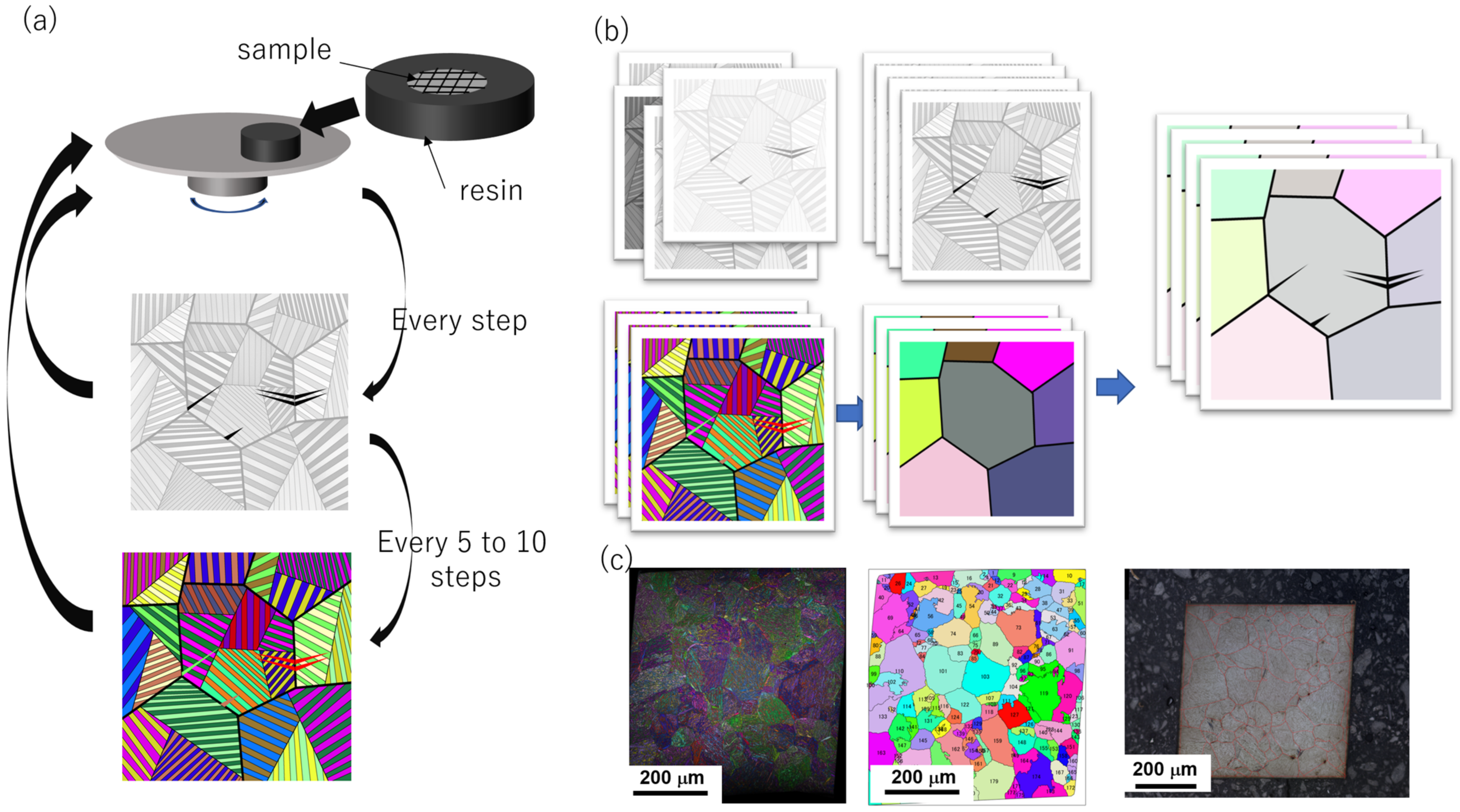
2. Materials and Methods
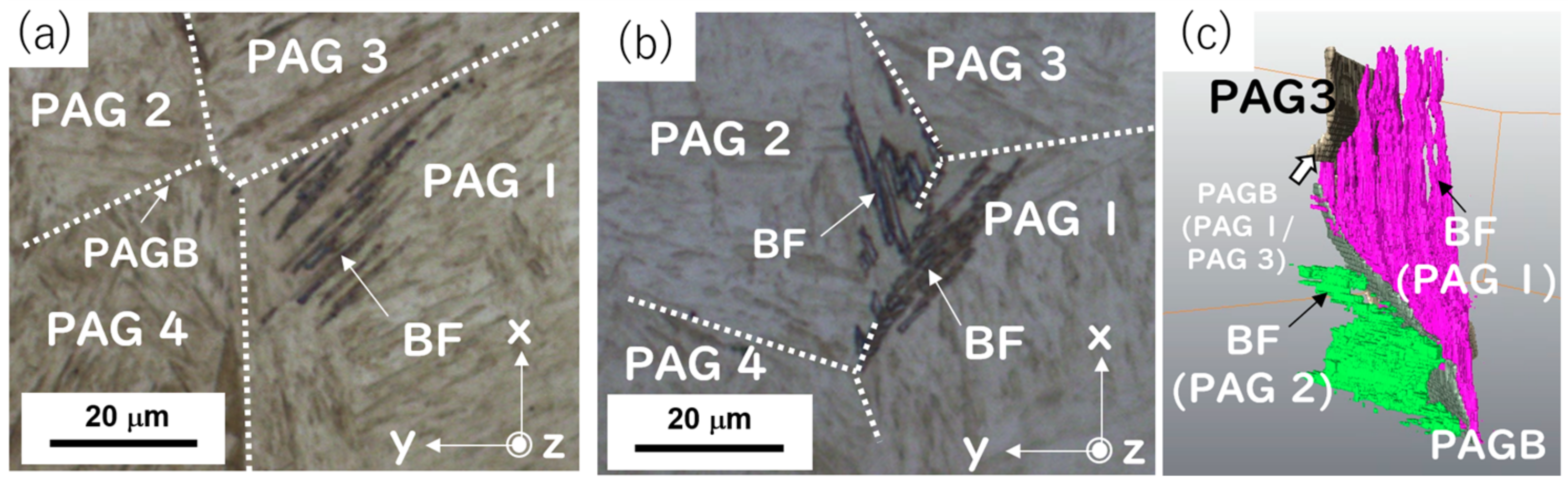
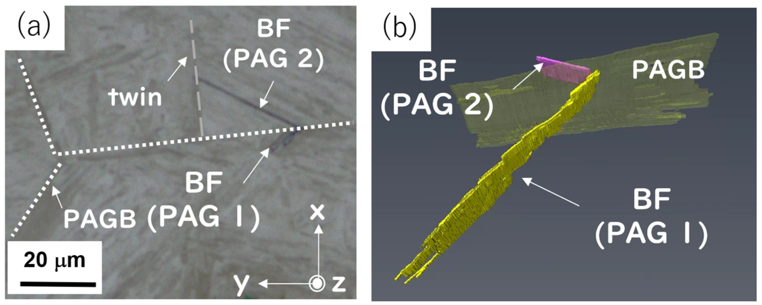
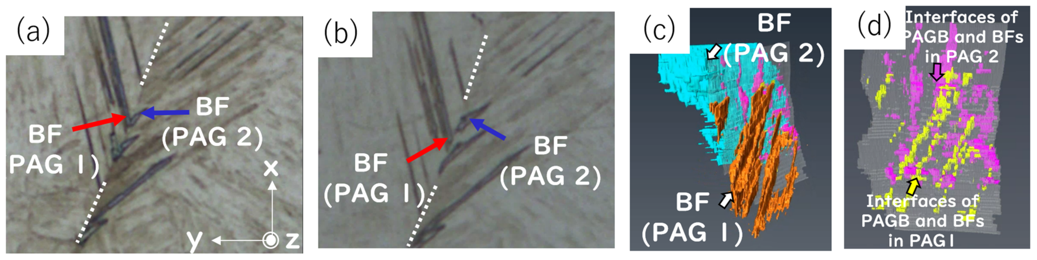
Steel with a chemical composition of Fe-0.39C-1.78Si-0.83Mn-0.97Cr-1.05Ni (in mass%) was used in this study. The steel was homogenized at 1200 °C for 24 h and cut into cylindrical samples, comprising 8 mm in diameter and 12 mm in height. Subsequent heat treatment was conducted using a thermomechanical simulator (Thermecmastor-Z, Fuji Electronic Industrial Co., Ltd., Kawasaki, Japan). The sample was austenitized at 1000 °C for 1200 s, followed by quenching to 450 °C, and maintained for 35 s to obtain partially transformed upper bainite microstructures. Approximately 5% of the bainitic transformation proceeded (estimated from the dilatation curve). Subsequently, the sample was cooled to room temperature to stop the bainite transformation by the transformation of untransformed austenite to martensite. (The definition of upper or lower bainite is not unified. The upper or lower bainite is classified based on the morphology of the BF [11,14] or carbide [15]. In the case of Si-containing steels, the bainite does not contain carbide [16,17]. Therefore, the bainite in this study is classified based on the morphology of BF; when the BFs form in a feather-like shape (parallel laths), they are classified as upper bainite.)
Figure 1a shows the schematic of the three-dimensional observation procedures. The center of the sample was cut out, and channels were created in a crisscross pattern to make quadrangular prisms in order to align the image correctly. The area of each quadrangular prism was about 500 μm × 500 μm. The sample was embedded in conductive resin. For the three-dimensional reconstruction of BFs and PAGs, distinguishing BFs and martensite is essential, as well as identifying the PAGs. Therefore, to distinguish BFs and martensite, the OM observations were conducted at every step after the polishing with 1 μm of alumina and etching with 2% Nital. To obtain the high-resolution images, the images were taken in 0.145 μm/pixel condition. The OM images were taken to have an overlap of about 25% with neighboring images, and 25 images were composed into one large image (about 600 μm × 600 μm) by using an image composite editor v2.0.3 (Microsoft). Scanning electron microscope (SEM) observations and electron back scattering diffraction (EBSD) measurements were performed every 5–10 steps in an SEM (JSM-7001FA, JEOL Ltd., Tokyo, Japan) equipped with an EBSD system. To keep a constant polishing rate, the sample was polished using a semi-automatic polishing machine (Struers, Copenhagen, Denmark). The polishing rate was about 1.1 μm/step, which was measured using a micrometer (Mitutoyo, Kawasaki, Japan), and the accuracy was also checked using the Vickers indent method [5]. The total number of slices was 120.
Figure 1b shows the image processing schematic for constructing the three-dimensional image. The OM images were first aligned manually, followed by automatic alignment by Fiji v1.53f51 [18] and its extensions [19]. The left image in Figure 1c shows the inverse pole figure (IPF) map of BFs and martensite. As shown in the left image in Figure 1c, the PAGs transformed martensite. Therefore, it was difficult to reconstruct the PAGs from the original EBSD data or the OM images. However, since the martensite and BFs hold the K-S OR with the PAG, it is possible to reconstruct the PAGs from the orientation of martensite and BFs. In this study, the PAG reconstructions were conducted using MTEX v5.1.1 [20] and parent-austenite-reconstruction-master [21]. Some PAGs were manually reconstructed because of their small size. The middle image in Figure 1c is the IPF map of the reconstructed PAGs. Next, the lines of the PAGBs were drawn on the OM images as shown by the red lines in the right image in Figure 1c, and three-dimensional images were constructed using the Avizo 9.7 software.

3. Results

Figure 2a shows the OM image of BFs and martensite; white dashed lines indicate the PAGBs. In Figure 2a, the BFs, which correspond to darkly etched laths, seem to have formed at the PAGB of PAG 1/PAG 3. Figure 2b is the OM image at the same position in the x- and y-directions as Figure 2a but at a different position in the z-direction. In Figure 2b, the BFs, which are identical to the BFs in Figure 2a, seem to have formed at the PAGB of PAG 1/PAG 2. Figure 2c shows the three-dimensional image corresponding to Figure 2a,b. The purple laths correspond to the BFs in PAG1, and the light green laths correspond to the BFs in PAG2. By the three-dimensional observation, it was confirmed that the parallel laths, called feather-like shapes [13], were formed at the PAGB.
From Figure 2c, it was confirmed that the BFs were more likely to have formed at the PAGB of PAG1/PAG2. The BFs in PAG1 were more likely to have collided with PAG3 as a result of the growth. As shown in Figure 2a, it is sometimes difficult to identify the formation site of BF, while via three-dimensional observation, the formation sites and the morphology of BFs can be evaluated more accurately.
Figure 3a,b shows the OM image and the corresponding three-dimensional image of the BFs, at the beginning of transformation before developing into feather-like shapes, which is the typical structure of upper bainite [13]. It was revealed that BFs formed at the same place on both sides of the PAGB plane. Therefore, it is suggested that the BFs form on both sides of the PAGB, even in a very initial stage.
The development of BFs at the PAGB was examined. Figure 4a,b shows the OM images at the same position in the x- and y-directions but at different positions in the z-direction. In Figure 4a,b, the identical BFs are indicated by red and blue arrows. In Figure 4a, the BFs indicated by the arrows are connected at the PAGB, while in Figure 4b, the BFs indicated by the arrows are not connected. Figure 4c shows the three-dimensional image corresponding to Figure 4a,b. In Figure 4c, the BFs in PAG1 are shown in orange, and the BFs in PAG2 are shown in light blue. The contact regions of the PAGB and the BFs in PAG1 are shown in yellow, and the contact regions of the PAGB and the BFs in PAG2 are shown in purple. Figure 4d shows only these contact regions by setting the BFs to be fully transparent. It can be seen that the yellow regions (the contact regions of BFs in PAG1 and PAGB) and purple regions (the contact regions of BFs in PAG2 and PAGB) are not parallel to each other. This result suggests that the BFs are not necessarily connected at the PAGB plane when the BFs develop into the feather-like morphology. It is because the habit plane of BFs is crystallographically restricted [2]. Based on the results of Figure 2, Figure 3 and Figure 4, it appears that BFs first form at the same place on both sides of the PAGB and then develop into feather-like shapes following the crystallographic orientation relationship with each PAG.
Figure 5a shows the OM image of the BFs and martensite. The white dotted lines correspond to the PAGBs, and the gray dashed lines correspond to the twin boundaries. Figure 5b shows the corresponding three-dimensional image. In Figure 5b, the transparent grains correspond to the PAGs, and the solid laths correspond to the BFs. It can be seen that the BFs form at the PAGB edges or planes. The formation sites of BFs were analyzed from the eight PAGs and the neighboring PAGs, and the results are summarized in Figure 5c. (It can be seen that the BFs colored in pink in PAG1 and the BFs colored in light green in PAG2 formed at the PAGB plane and PAGB edge as well. In that case, the formation site of BFs were judged by focusing on the longest BF, which is considered to be formed first.) Figure 5c describes the numbers of the PAGB edges and PAGB planes where BFs were formed and the PAGBs where BFs were not formed. The red, blue, and gray correspond to the PAGBs where BFs were formed on both sides of the PAGB, the PAGBs where BFs were formed on one side of the PAGB, and the PAGB where BFs were not formed at the PAGB, respectively. The numbers of PAGB edges and planes where BFs were formed were 6 out of 118 and 13 out of 71, respectively. It was found that the BFs mainly formed on both sides of the PAGB planes, as shown in red in Figure 5c. In the case of the formation of BFs at the PAGB edge, the BF(s) formed at one or two PAG(s) out of three PAGs that compose the PAGB edges. The formation of the BFs at three PAGs was not found in this study. Based on the classical nucleation theory [22], the edge should be more favored; thus, it is difficult to explain the formation of BFs at the PAGB planes rather than the edges.
Crystal orientation analysis of BFs at PAGB was conducted. Figure 6a shows the highlighted IQ map of BFs and martensite. Figure 6b shows the corresponding (001)α pole figure. In Figure 6a, the BFs in PAG1 and the BFs in PAG2 are shown in red and green, respectively. The martensite is colored based on the PAGs: PAG1: dark gray; PAG2: light gray; PAG3: orange; and PAG4: purple. From Figure 6b, it can be seen that the orientation of the BFs in PAG1 and the orientation of the BFs in PAG2 was close. Thus, the interfacial energy of BFs across the PAGB was considered to be low because the misorientation angle between the BFs across the PAGB ( Δ θ B F γ 1 | B F γ 2 ) was small [4,5]. The Δ θ B F γ 1 | B F γ 2 of other BFs which formed on both sides of the PAGBs were measured. Figure 6c summarizes the number of BFs with each Δ θ B F γ 1 | B F γ 2 . It was revealed that more BFs were formed having small Δ θ B F γ 1 | B F γ 2 .

4. Discussion

It was observed that the BFs formed on both sides of the PAGB plane and the Δ θ B F γ 1 | B F γ 2 was small. Since the BF holds the K-S OR with the PAG, the orientation of BFs is restricted to twenty-four variants. Thus, the value of Δ θ B F γ 1 | B F γ 2 at a PAGB depends not only on the selected variant but also on the crystal orientation of PAGs. Therefore, Δ θ B F γ 1 | B F γ 2 can be estimated by the crystal orientation of PAGs. For instance, it is assumed that the BFs form at the PAGB of PAG2 (shown in light gray) and PAG3 (shown in orange) in Figure 6a. As shown in Figure 6b, the orientations of the variants in PAG2 and the orientation of the variants in PAG3 are quite far. Thus, the Δ θ B F γ 1 | B F γ 2 is large for any pair of BFs at the PAGB of PAG2 and PAG3. It would be difficult for BFs to form at the PAGB, since the BFs cannot form having small Δ θ B F γ 1 | B F γ 2 . Then, we defined the possible minimum misorientation angle between all variant pairs across the PAGB plane and PAGB edge as KSmin(plane) and KSmin(edge).
The KSmin(plane) is defined as:
K S m i n p l a n e = min i , j = 1 , 1   24 , 24 Δ θ V i γ 1 , V j γ 2   .
Here, Δ θ V i γ 1 , V j γ 2   is the misorientation angle between the i-th variant of γ1 and j-th variant of γ2. In the case of the BFs formation at the PAGB edge, the calculation of KSmin(edge) is a bit complicated because there are three PAGBs (γ1/γ2, γ2/γ3, and γ3/γ1). In the case of the diffusional transformation, the ferrite forms across the PAGBs [7]. The crystal orientation of ferrite is the same across the PAGBs. In the classical nucleation theory [22], it is assumed that the precipitate in the same crystal orientation forms across the PAGB as observed in the ferrite nucleation. In order to minimize the free energy of activation for the formation of the critical nucleus, the interfacial energies of all three interfaces should be minimized. Thus, the KSmin(edge) is defined as:
K S m i n e d g e = min i , j , k = 1 , 1 , 1   24 , 24 , 24 max Δ θ V i γ 1 , V j γ 2   , Δ θ V j γ 2 , V k γ 3   , Δ θ V k γ 3 , V i γ 1   .
Figure 7a shows the OM image of the sample with PAGBs. The colors of the PAGBs correspond to the KSmin(plane), and red arrows indicate the PAGBs where the BFs were formed. It is demonstrated that the KSmin(plane) differs depending on the orientations of the PAGs and the BFs formed at the PAGBs colored by blue, which means that the BFs formed at the PAGBs whose KSmin(plane) were smaller than 5°.
Figure 7b,c shows the numbers of PAGB planes and PAGB edges with each KSmin(plane) and KSmin(edge). In Figure 7b,c, the PAGBs where BFs were formed are shown in red, and the PAGBs where BFs were not formed are shown in gray. The formations of the BFs were examined throughout the PAGBs of the three-dimensional image. It was revealed that the BFs formed at the PAGBs with smaller KSmin(plane) values, which means that the PAGBs with smaller KSmin(plane) values have higher potency for the BF formation. Therefore, the potency for BF formation can be estimated by the KSmin(plane) value. Comparing the distribution of the KSmin(plane) and KSmin(edge), the proportion of the PAGB edges whose KSmin(edge) was smaller than 5°, which is supposed to be the more favored nucleation site, was very low. It is considered that the BFs mainly form at the PAGB plane because very few edges existed that are supposed to be crystallographically-favored nucleation sites.

5. Conclusions

By combining OM-based serial sectioning techniques and crystal orientation analysis using EBSD, three-dimensional images of BFs and PAGs were constructed. The formation site and the effect of the orientation of the PAGs on the formation of BFs were quantitatively analyzed in three dimensions. It was revealed that the BFs mainly formed at the PAGB planes rather than PAGB edges and formed at the same plane on both sides of the PAGB by the three-dimensional observation. In most cases, the misorientation angles between the BFs across the PAGB were small. It is suggested that the reason for the formation of BFs at the PAGB plane rather than PAGB edges is because of the difficulty of BFs having the small misorientations with the BFs in the adjacent PAGs at the edges.

Author Contributions

Conceptualization, S.J. and S.N.; methodology, S.J. and S.N.; validation, S.J. and S.N.; formal analysis, S.J.; investigation, S.J.; resources, S.N.; data curation, S.J.; writing—original draft preparation, S.J.; writing—review and editing, S.N.; visualization, S.J.; supervision, S.N.; project administration, S.N.; funding acquisition, S.N. All authors have read and agreed to the published version of the manuscript.

Funding

This research was conducted as part of a project supported by JSPS KAKENHI (Grant Number 20H02475).

Institutional Review Board Statement

Not applicable.

Informed Consent Statement

Not applicable.

Data Availability Statement

Data are not available since the data in this study are being used in our current research.

Conflicts of Interest

The authors declare no conflict of interest.

References

  1. Cooman, B.C.D. Structure–properties relationship in TRIP steels containing carbide-free bainite. Curr. Opin. Solid State Mater. Sci. 2004, 8, 285–303. [Google Scholar] [CrossRef]
  2. Bhadeshia, H.K.D.H. Bainite in Steels: Theory and Practice; CRC Press: Boca Raton, FL, USA, 2019. [Google Scholar]
  3. Kurdjumow, G.; Sachs, G. Uber den Mechanismus der Stahlhartung. Z. Phys. 1930, 64, 325–343. [Google Scholar] [CrossRef]
  4. Kaneshita, T.; Miyamoto, G.; Furuhara, T. Variant selection in grain boundary nucleation of bainite in Fe-2Mn-C alloys. Acta Mater. 2017, 127, 368–378. [Google Scholar] [CrossRef]
  5. Furuhara, T.; Kawata, H.; Morito, S.; Miyamoto, G.; Maki, T. Variant selection in grain boundary nucleation of upper bainite. Metall. Mater. Trans. A 2008, 39, 1003–1013. [Google Scholar] [CrossRef]
  6. Nagano, T.; Enomoto, M. Calculation of the interfacial energies between α and γ iron and equilibrium particle shape. Metall. Mater. Trans. A 2006, 37, 929–937. [Google Scholar] [CrossRef]
  7. Hata, K.; Fujiwara, K.; Kawano, K.; Sugiyama, M.; Fukuda, T.; Kakeshita, T. Reconstruction of the three-dimensional ferrite-austenite microstructure and crystallographic analysis in the early stage of reverse phase transformation in an Fe-Mn-C alloy. ISIJ Int. 2018, 58, 323–332. [Google Scholar] [CrossRef]
  8. Zhang, G.H.; Takeuchi, T.; Enomoto, M.; Adachi, Y. Influence of crystallography on ferrite nucleation at austenite grain-boundary faces, edges, and corners in a Co-15Fe alloy. Metall. Mater. Trans. A 2011, 42, 1597–1608. [Google Scholar] [CrossRef]
  9. Enomoto, M.; Lange, W.F.; Aaronson, H.I. The kinetics of ferrite nucleation at austenite grain edges in Fe-C and Fe-C-X alloys. Metall. Mater. Trans. A 1986, 17, 1399–1407. [Google Scholar] [CrossRef]
  10. Umezaki, A.; Enomoto, M. Estimation of number of precipitate particles per unit volume from measurements on polished specimen surfaces—Computer simulation. ISIJ Int. 2000, 40, 1142–1148. [Google Scholar] [CrossRef]
  11. Oka, M.; Okamoto, H. Variation of Transition Temperatures from Upper to Lower Bainites in Plain Carbon Steels. J. Phys. IV Fr. 1995, 5, C8-503-508. [Google Scholar] [CrossRef] [Green Version]
  12. Kang, J.S.; Seol, J.B.; Park, C.G. Three-dimensional characterization of bainitic microstructures in low-carbon high-strength low-alloy steel studied by electron backscatter diffraction. Mater. Charact. 2013, 79, 110–121. [Google Scholar] [CrossRef]
  13. Morito, S.; Edamatsu, Y.; Ichinotani, K.; Ohba, T.; Hayashi, T.; Adachi, Y.; Furuhara, T.; Miyamoto, G.; Takayama, N. Quantitative analysis of three-dimensional morphology of martensite packets and blocks in iron-carbon-manganese steels. J. Alloys. Compd. 2013, 577, S587–S592. [Google Scholar] [CrossRef]
  14. Tsuzaki, K.; Kodai, A.; Maki, T. Formation mechanism of bainitic ferrite in an Fe-2 Pct Si-0.6 Pct C alloy. Metall. Mater. Trans. A 1994, 25, 2009–2016. [Google Scholar] [CrossRef]
  15. Bramfitt, B.L.; Speer, J.G. A perspective on the morphology of bainite. Metall. Trans. A 1990, 21, 817. [Google Scholar] [CrossRef]
  16. Tsuzaki, K.; Nakao, C.; Maki, T. Formation Temperature of Bainitic Ferrite in Si-Containing Steels. Mater. Trans. JIM 1991, 32, 658–666. [Google Scholar] [CrossRef]
  17. Caballero, F.G.; Bhadeshia, H.K.D.H. Very strong bainite. Curr. Opin. Solid State Mater. Sci. 2004, 8, 251. [Google Scholar] [CrossRef]
  18. Schindelin, J.; Carreras, I.A.; Frise, E.; Kaynig, V.; Longair, M.; Pietzsch, T.; Preibisch, S.; Rueden, C.; Saalfeld, S.; Schmid, B.; et al. Fiji: An open-source platform for biological-image analysis. Nat. Methods 2012, 9, 676–682. [Google Scholar] [CrossRef] [PubMed]
  19. Thevenaz, P.; Ruttimann, U.E.; Unser, M. A pyramid approach to subpixel registration based on intensity. IEEE Trans. Image Process. 1998, 7, 27–41. [Google Scholar] [CrossRef] [PubMed]
  20. Bachmann, F.; Hielscher, R.; Schaeben, H. Texture analysis with MTEX- Free and open source software toolbox. Solid State Phenom. 2010, 160, 63–68. [Google Scholar] [CrossRef]
  21. Niessen, F.; Nyyssönen, T.; Gazder, A.A.; Hielscher, R. Parent grain reconstruction from partially or fully transformed microstructures in MTEX. J. Appl. Crystallogr. 2022, 55, 180–194. [Google Scholar] [CrossRef] [PubMed]
  22. Porter, D.A.; Easterling, K.E.; Sherif, M.Y. Phase Transformations in Metals and Alloys; CRC Press: Boca Raton, FL, USA, 2009. [Google Scholar] [CrossRef]
Figure 1. The schematic of the three-dimensional observation procedures. (a) The schematic of serial sectioning. (b) The schematic of the image processing. (c) The IPF map of bainitic ferrites (BFs) and martensite, the IPF map of reconstructed prior austenite grains (PAGs), and the optical microscopy (OM) image with PAGBs drawn by red lines.
Metals 13 00355 g001
Figure 2. (a) The OM image of BFs, (b) a different layer, and (c) the corresponding three-dimensional image.
Metals 13 00355 g002
Figure 3. (a) The OM image of BFs, and (b) the corresponding three-dimensional image.
Metals 13 00355 g003
Figure 4. (a) The OM image of BFs, (b) the OM image of BFs at the same position in x- and y-directions but different positions in the z-direction. The identical BFs are indicated by the red and blue arrows, respectively. (c) the corresponding three-dimensional image, and (d) the contact regions of the BFs and the PAGB plane (yellow: contact regions of BFs in PAG 1 and PAGB, purple: contact regions of BFs in PAG 2 and PAGB).
Metals 13 00355 g004
Figure 5. (a) The OM image of BFs and (b) the corresponding three-dimensional image. (c) The formation tendencies of BFs at PAGB edges and planes. (Red: PAGBs where BFs were formed on both sides of the PAGBs, blue: PAGBs where BFs were formed on one side of the PAGBs, gray: PAGBs where BFs were not formed.).
Metals 13 00355 g005
Figure 6. (a) Highlighted IQ map, and (b) the corresponding (0 0 1)α pole figure highlighted following by (a). (c) The distribution of the misorientation angles between the BFs across the PAGBs.
Metals 13 00355 g006
Figure 7. (a) OM image with PAGBs colored by the KSmin value, (blue: 0° to 5°, green: 5° to 10°, yellow: 10° to 15°, orange: bigger than 15°: purple: twin boundaries) and red arrows show the PAGBs where BFs were formed. The distribution of the KSmin values of PAGB and the formation tendencies of BFs at each KSmin value at PAGB (b) planes and (c) edges.
Metals 13 00355 g007
Disclaimer/Publisher’s Note: The statements, opinions and data contained in all publications are solely those of the individual author(s) and contributor(s) and not of MDPI and/or the editor(s). MDPI and/or the editor(s) disclaim responsibility for any injury to people or property resulting from any ideas, methods, instructions or products referred to in the content.

