Article

Weld Quality Analysis of High-Hardness Armored Steel in Pulsed Gas Metal Arc Welding

1
Department of Smart Manufacturing Engineering, Changwon National University, 20, Changwondaehak-ro, Uichang-gu, Changwon-si 51140, Republic of Korea
2
Korea Textile Machinery Convergence Research Institute, 27, Sampung-ro, Gyeongsan-si 38542, Republic of Korea
3
School of Mechanical Engineering, University of Ulsan, Ulsan 44610, Republic of Korea
4
Best F.A Co., Ltd., Yeondeok-ro, Seongsan-gu, Changwon-si 51571, Republic of Korea
*
Author to whom correspondence should be addressed.
These authors contributed equally to this work.
Metals 2023, 13(2), 303; https://doi.org/10.3390/met13020303
Submission received: 5 January 2023 / Revised: 27 January 2023 / Accepted: 27 January 2023 / Published: 2 February 2023
(This article belongs to the Section Welding and Joining)

Abstract

:
As improving fuel economy and performance through weight reduction in vehicles are recognized as important tasks, the defense industry is researching ways to reduce the weight of armor plates for combat vehicles and increase bulletproof performance and durability. Most armor plates in combat vehicles are manufactured using weld joints. High-hardness armor (HHA) is used to make armor plates; however, its mechanical properties deteriorate because of hydrogen embrittlement and high-temperature softening during welding. Welding defects, such as pores and cracks, occur frequently. In this study, HHA steel was subjected to single-pulse gas metal arc welding (GMAW), and the welding performance of the shielding gas and heat input was analyzed by the United States army tank-automotive and armaments command (TACOM) standard. The specimen cross-section was visually examined, and hardness, tensile, and impact tests were used to identify the mechanical properties based on the welding conditions. Additionally, flux cored arc welding (FCAW) and GMAW were used and compared, and spatter image analyses were used to assess the integrity of the welding process of the HHA plate applied to a combat vehicle. As a result of the experiment, as the CO2 content and heat input increased, the mechanical strength of the welded zone and the integrity of the welding process deteriorated.

1. Introduction

Recently, improvements in fuel efficiency and the performance of vehicles through weight reduction has been recognized as an important issue. Weight reduction in vehicles has become an essential development factor for reducing global warming and following environmental regulations [1,2]. Therefore, manufacturers in different industries are marketing their products using lightweight and strong materials to reduce overall product weight. In the defense industry, the application of lightweight materials is being actively studied. In the case of combat vehicles, research and development on weight reduction in armor plates are in progress [3,4]. The primary role of armor plates is to thwart enemy attacks, maintain the combat vehicle’s integrity, and protect combatants inside. Therefore, the bulletproof performance can be used as an important index for determining the armor plate material. Therefore, to improve the bulletproof performance of combat vehicles, a thick single-armor material was used in [5]. Although the bulletproof performance was excellent, the combat capability was reduced owing to the increase in weight. The increased weight resulted in a reduction in fuel economy and limited the range of movement in the combat area and the transfer of troops, which is the most important role of the combat vehicle. Therefore, recently, research has been conducted to maintain bulletproof performance and reduce the thickness of the plate material to lighten the combat vehicles [6].
Various metal armor materials are being developed based on the demand for weight reduction. Materials, such as titanium alloys and ceramics, are used as non-ferrous armor materials. Titanium alloys and ceramic materials are only used in specific locations because of their high manufacturing costs and their difficulty in welding and processing. Steel armor plates are preferred because of their relatively low price, excellent strength, and weldability. The high-hardness armor (HHA) sheet material attains high hardness through rapid cooling after heat treatment, and it has good bulletproof performance. Rolled homogeneous armor (RHA) sheet materials attain relatively low hardness through air cooling and rolling processes but high resistance to brittle fracture. Recently, the use of HHA plates and the development of ultra-high-hardness armor (UHHA) plates have attracted attention [6,7,8,9,10,11]. Armor plates welded together form the structure of combat vehicles. In the past, the majority of them were manufactured by welding; however, owing to automation technology and the robot industry, the application of semi-automatic and automatic systems has rapidly increased. The development of armor plate material can be flawed by welding defects; therefore, it is necessary to apply and develop a new welding process.
Arc welding is the most widely used welding methods in industrial sites because its initial equipment cost is lower than that of other welding methods, and high productivity can be expected because of its widespread use. Arc welding is frequently used for armored plates, and research on this process is being actively conducted. In 1996, Alkemade changed the preheating temperature and heat input conditions using the gas metal arc welding (GMAW) technique to check for cracks and the hardness of three types of welding materials. Ferritic and austenitic stainless materials and duplex austenitic/ferritic stainless materials were used as welding materials. A welding material with a lower tensile strength than the base material was used. A Y-groove specimen was prepared as a test specimen using a 509–568 HV grade HHA plate. The preheating temperature was set at 0~150 °C, and the heat input was 0.5~1.4 kJ/mm. Cracks did not occur in a heat input range of 1.0~2.5 kJ/mm and a preheating temperature range of 50–75 °C. Regarding the crack type, it was confirmed that the crack occurred at the center of the weld, and the crack started at the root of the weld and progressed to the tow of the weld along the weld boundary. Based on the experimental results, it was confirmed that the hardness was significantly reduced, owing to hot softening in the three types of welding material specimens. It was confirmed that the weld with austenitic stainless steel exhibited the lowest hardness [12,13,14]. In 2008, Magudeeswaran et al. published three papers using shield-metal arc welding (SMAW) and flux cored arc welding (FCAW) methods to produce HHA plates using austenitic stainless steel and low-hydrogen ferritic welding materials. The welds of the HHA plates where the welding material for stainless steel was used were examined for their degree of hydrogen diffusion, tensile strength, toughness, and fatigue strength. The hydrogen-diffusion test showed that the austenitic stainless steel welding material contained less hydrogen than the low-hydrogen ferritic welding material. It was confirmed that the FCAW method had a higher hydrogen-diffusion resistance than the SMAW method. The results of the tensile strength and impact tests using low-hydrogen ferritic welding material revealed a high tensile strength of the weld [15,16,17,18,19]. Additionally, as research on additive manufacturing has been conducted recently, various studies on defect analyses of weldments, such as bead shape analyses and internal defect detection, are being conducted [20,21,22,23].
In this study, the mechanical properties of HHA plates, such as cross-sectional porosity, hardness distribution, tensile strength, and impact characteristics, were reviewed in relation to the amount of welding heat input and shielding gas in the single-pulse GMAW process. The differences were compared and analyzed by additionally performing the FCAW process. Moreover, image analyses were used to evaluate the soundness of the appearance of the welded part, confirm the amount of spatter generated, and identify the optimal welding conditions for the HHA plate.

2. Experimental Methods

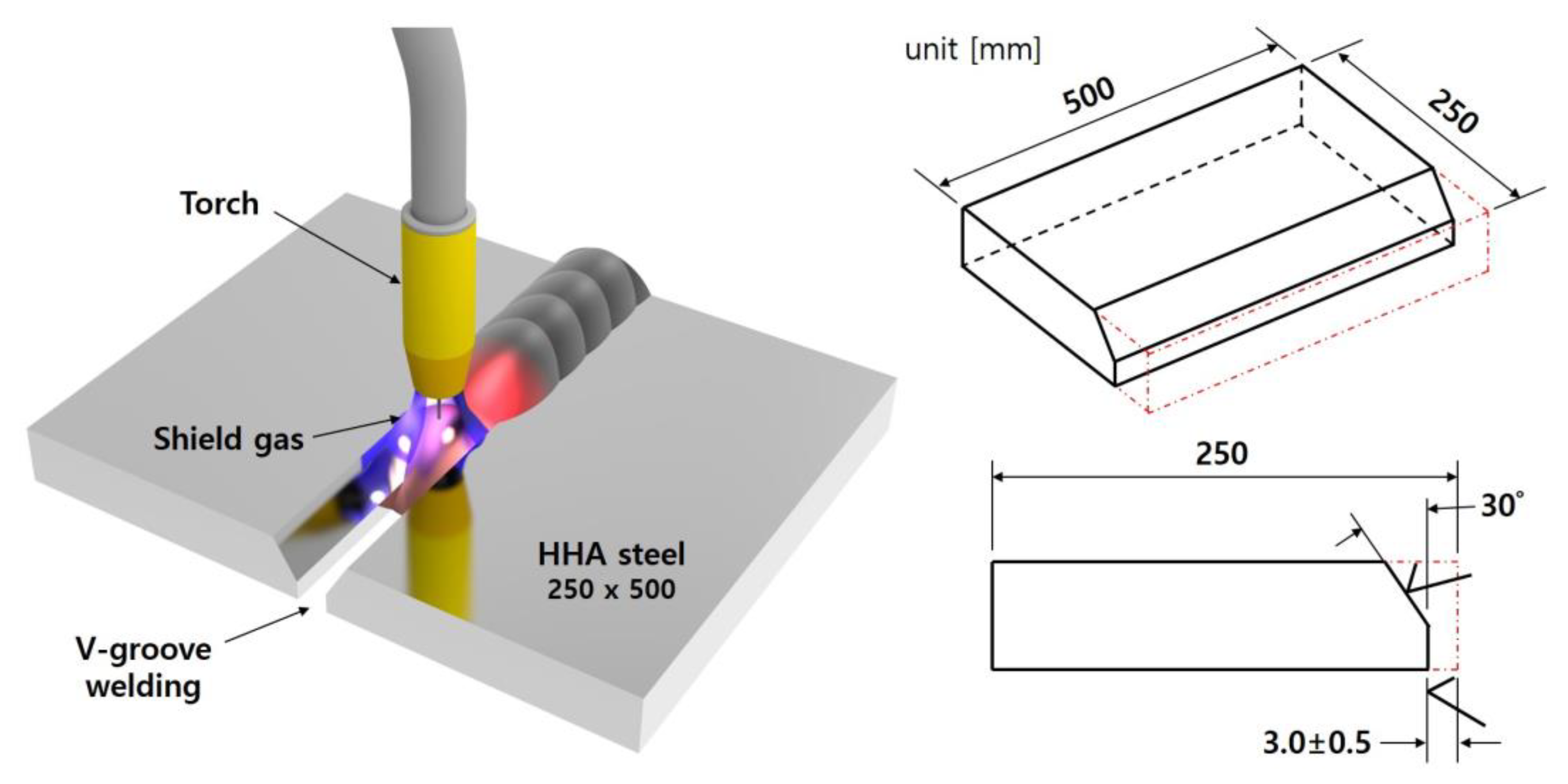
2.1. Experimental Equipment and Materials

To determine the single-pulse GMAW process conditions in this study, 600A class GLC 603 QUINTO welding equipment and QUINTO 6-axis welding robots (Cloos, Haiger, Germany) were used. The base material used in the experiment was 12 t (12 mm) of a domestic HHA plate with a Vickers hardness of 460–510 HV and a tensile strength of 1600–1700 MPa. The welding material was a solid wire, and the welding material used in the manufacturing of domestic submarines was applied. Additionally, the FCAW process was considered using a flux-cored wire equivalent to the tensile strength of the solid wire. Table 1 and Table 2 list the mechanical and chemical properties of the welding materials used, respectively. A previous study on an ER120S-G foreign HHA plate was selected as the test material [24,25,26,27]. For the welding specimen, a 250 mm × 500 mm V-groove specimen was prepared, multi-pass welding was performed, and the welding test was performed by processing it to the dimensions shown in Figure 1.

2.2. Experimental Method

Preheating before welding is recommended to prevent hydrogen embrittlement and cracking in HHA plates. Experiments were conducted in compliance with the preheating temperature (150 °C) of foreign-made HHA plates. Preheating was performed using a preheating torch, and ceramic backing was performed to smooth the formation of the back bead. The applied weld joint was a butt joint, and the section inspection, tensile, impact, and hardness were evaluated according to the TACOM standard, which is the standard of the Defense Industry and Logistics Command of the United States [28,29,30,31,32]. Torch weaving was performed during welding to improve the joining quality.

2.3. Test and Evaluation Standards

Specimens were manufactured in accordance with the TACOM requirements; defects were evaluated for compliance to the GMAW groove-welding standards. For cross-section inspection, after polishing the cross-section of the welding specimen, etching was performed using a 3% nital (3% HNO3 to 97% ethyl alcohol) solution. The weldment, heat-affected zone (HAZ), and fusion line of the etched cross-section were visually confirmed. The tensile test was conducted using the specimen size specified in the TACOM standard and the standard supported by the equipment at a test speed of 3 mm/min. In the standard, 15 mm thickness was taken in the direction perpendicular to the welding line and two repeated experiments were performed. The Vickers tests were performed for the hardness test, and the diamond shape indenter was used. In the Vickers tests, the hardness profile was confirmed using HV1, and the hardness values were measured at intervals of 2 mm in the weld zone, HAZ, and base metal. In the impact test, the Charpy test was performed at low temperatures and room temperature. The impact test was repeated three times. The specimen production and testing were evaluated in compliance with ASTM standards.

2.4. Welding Conditions

To select a welding shielding gas for HHA plates, a mechanical evaluation was conducted using argon-gas-based O2 2% and CO2 5%. The final selected conditions are listed in Table 3. The ratio of the shielding gas and the detailed heat input conditions were determined based on the selected welding shielding gas.

3. Mechanical Characterization

3.1. Evaluation of Mechanical Properties for Application to O2 and CO2 Shielding Gases

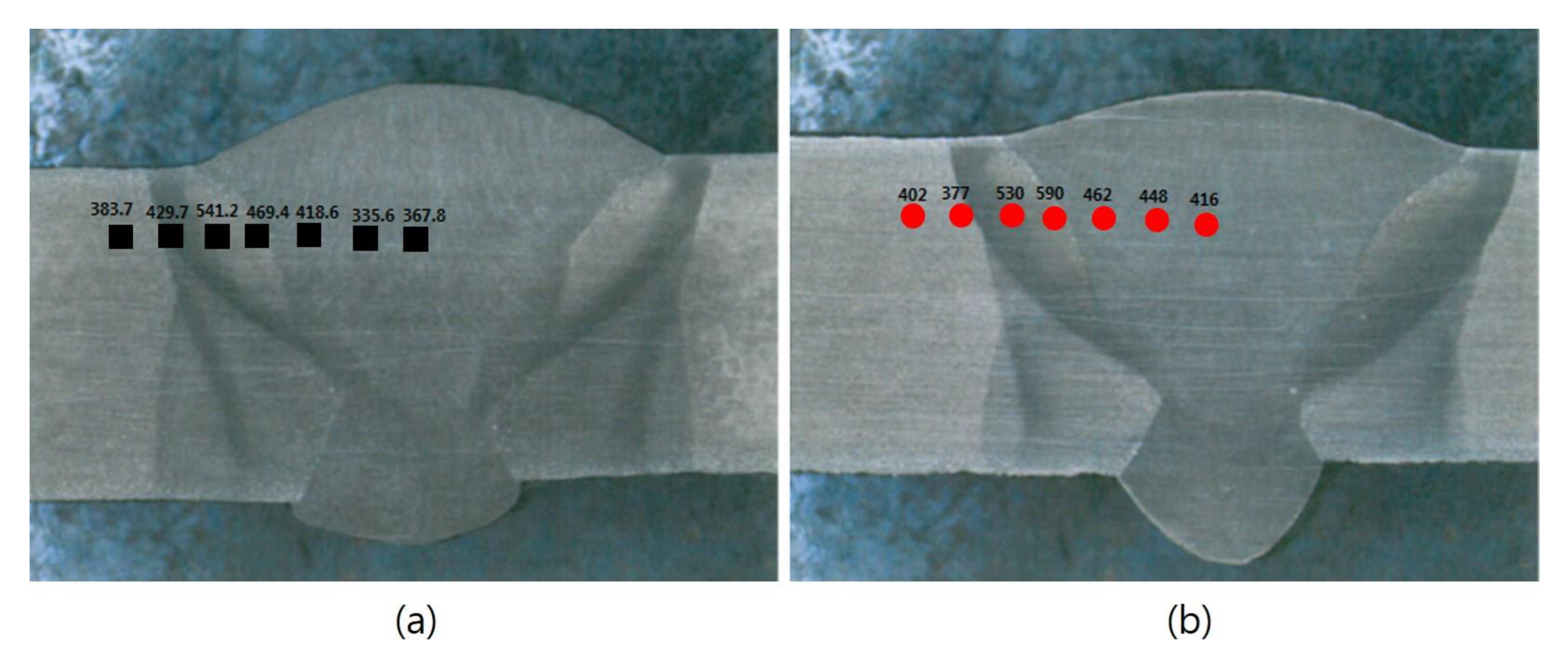
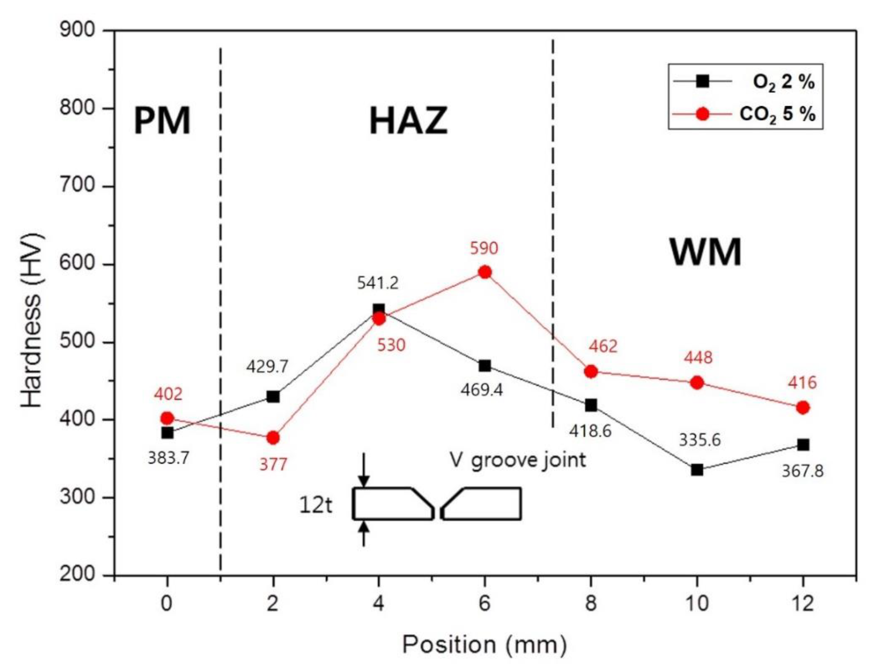
3.1.1. Cross-Section Analyses and Hardness Distribution Confirmation Result

The maximum hardness value increased when O2 was used as the shielding gas rather than CO2 when the hardness profile of the cross-section was assessed. However, the hardness of the welded part was confirmed to be high when CO2 shielding gas was used under all conditions. A high-hardness value near the fusion line in the butt joint is judged to indicate hardened tissue, and the hardness profile pictures and graphs of the butt joint are shown in Figure 2 and Figure 3. No singularity was identified under all conditions during the hardness test or during the visual inspection of pores and cracks in the cross-section.

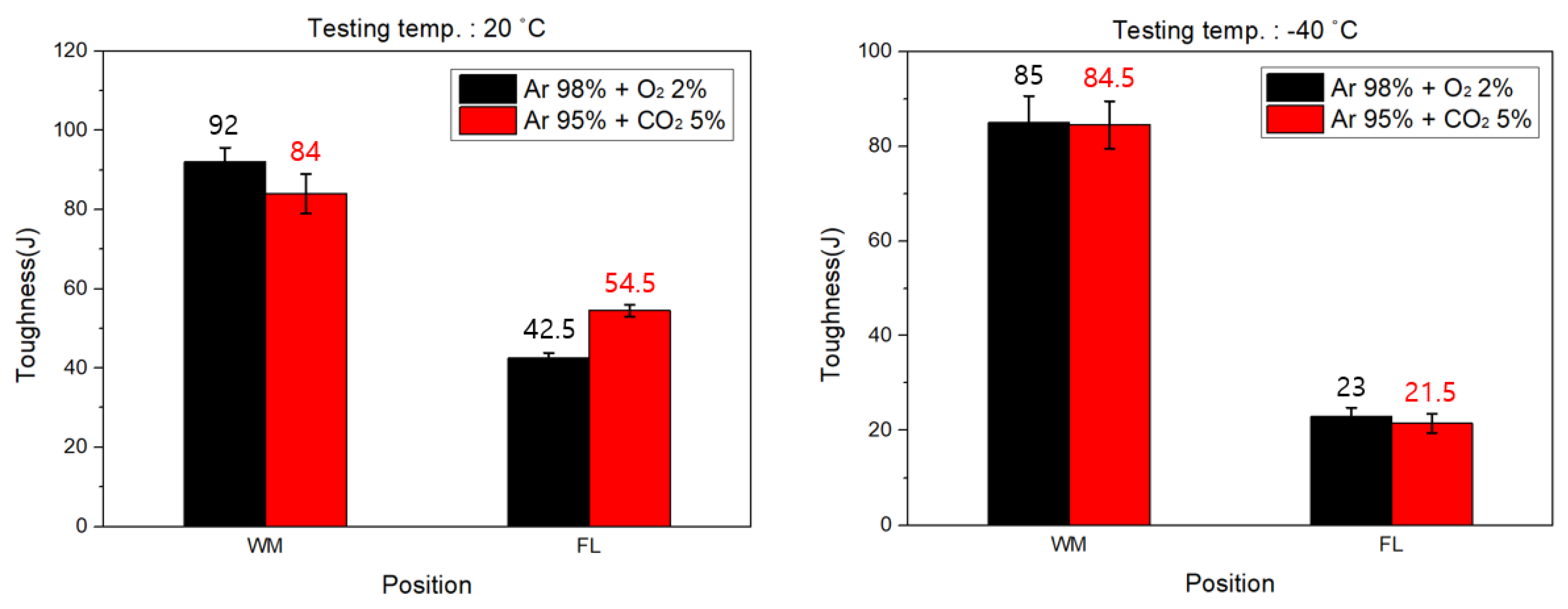
3.1.2. Impact Test Results

The Charpy impact test was carried out twice, once at low temperature (−40 °C) and once at room temperature (20 °C). The room temperature and low temperature impact values of the weld zone were confirmed to be higher than the minimum Charpy impact value of the base material in MIL-DTL-46100E. It was confirmed that the impact value of the fusion line was higher when using 5% CO2 shielding gas rather than O2 2% condition. This is because CO2 creates a narrow and deep arc due to its high energy density. Therefore, due to the high heat input relative to the area, the welding zone and the fusion line under the CO2 condition, where the thermal effect is significant, have high hardness and impact values. Figure 4 shows a graph summarizing the results.

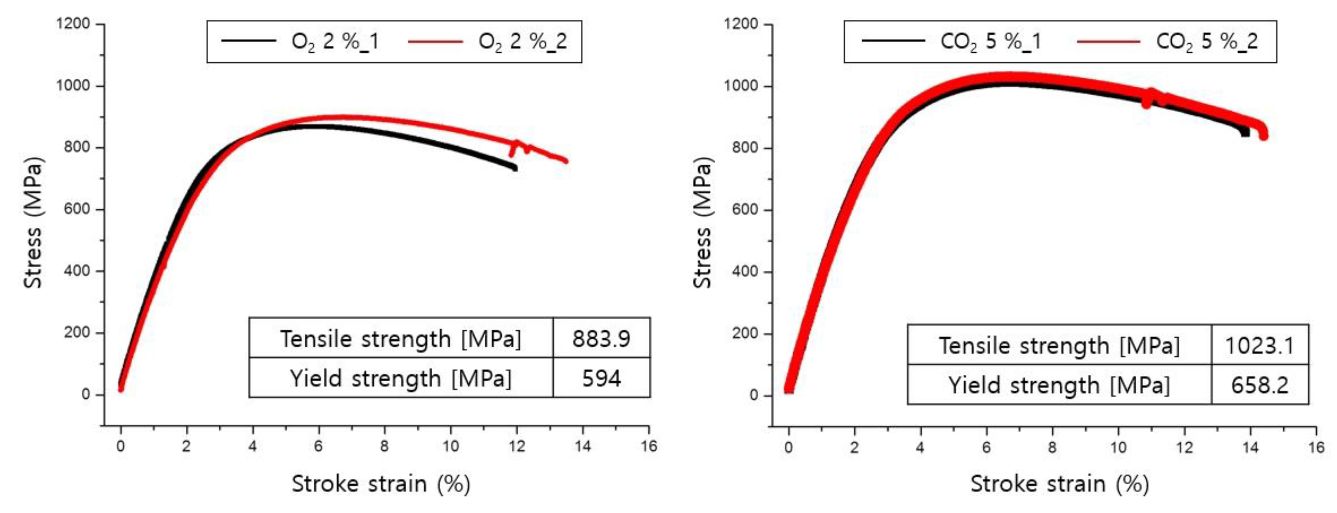
3.1.3. Tensile Test Results

A tensile test was performed twice for each shielding gas condition, according to the standard. The findings indicate that when CO2 shielding gas was used, the tensile strength of the welded part increased by 139.2 MPa compared to the O2 shielding gas application conditions. The tensile test results based on the tensile strength of the used welding material showed an increase in tensile strength of 193.1 MPa. Figure 5 shows the tensile test results.

3.2. Evaluation of Mechanical Properties According to CO2 Shielding Gas Ratio and Heat Input in GMAW and FCAW

Based on the basic experiment for selecting the shielding gas, the conditions of the final pulse GMAW were determined by testing the detailed conditions according to the shielding gas and heat input, as listed in Table 4. In addition, the FCAW process, which is characterized by low-hydrogen embrittlement by forming slag, was added to the experimental conditions to compare the amount of spatter and mechanical strength with the welding process of GMAW [33,34,35].

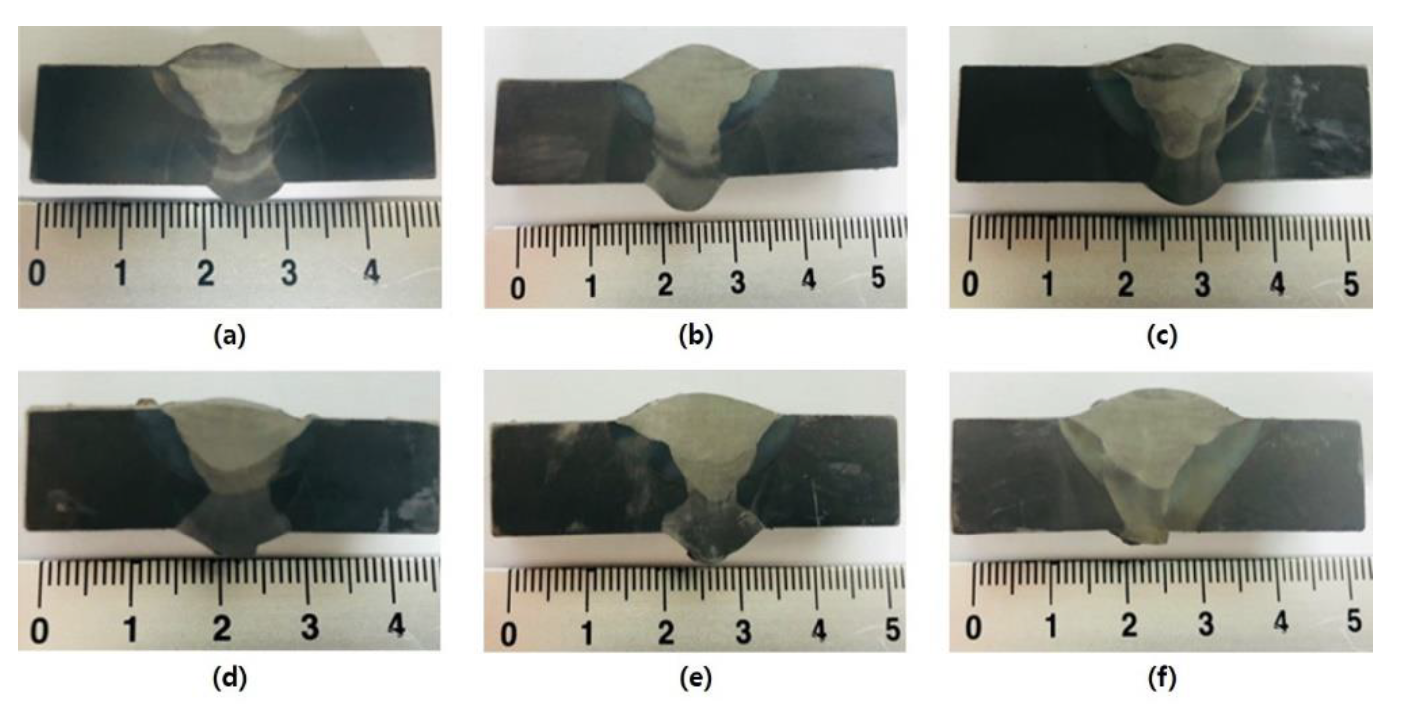
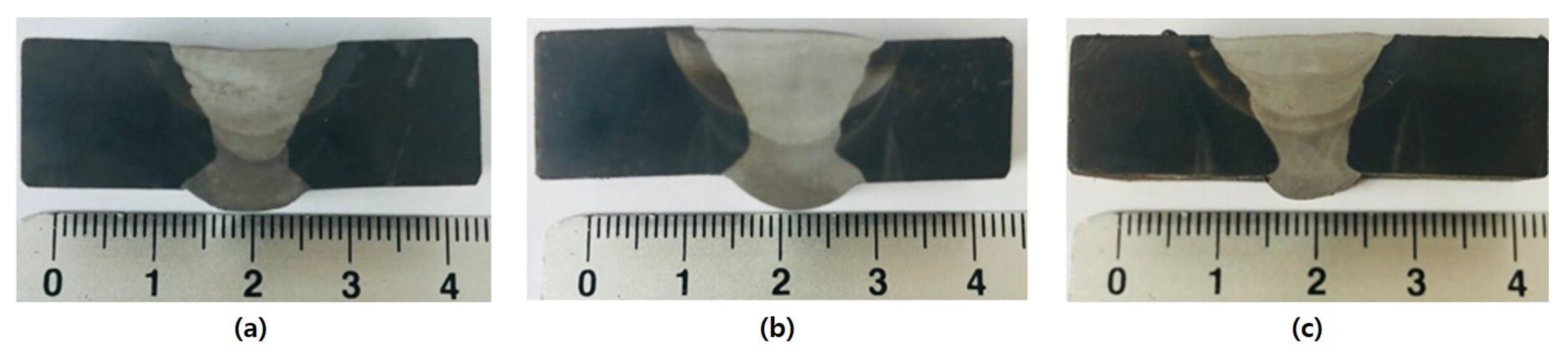
3.2.1. Cross-Section Analyses Results

Cracks and pores were examined according to changes in the heat input and shielding gas. Usually, argon shielding gas increases arc stability and forms a good looking bead. However, when argon shielding gas is used, it is used in combination with a CO2 shielding gas, which generates an arc with high density through the thermal pinch effect because it has low penetrability. Because of the butt joint cross-section analyses, as shown in Figure 6, when the content of CO2 gas increased, it was confirmed that a deep and wide welded part formed. When the CO2 content decreased and the argon gas content increased, a relatively high surface bead and a narrow penetration width were formed. As the heat input increased, the area of the heat-affected and weld zones increased, and pores and cracks were not observed.
The FCAW weld’s cross-sectional analyses confirmed that there were no pores or defects in the weld in relation to the heat input and that the width of the weld increased as the heat input increased. Figure 7 shows the results of the cross-sectional analyses of the butt joint and demonstrates that the size of the welded part of the butt joint changed relatively little depending on the amount of heat input.

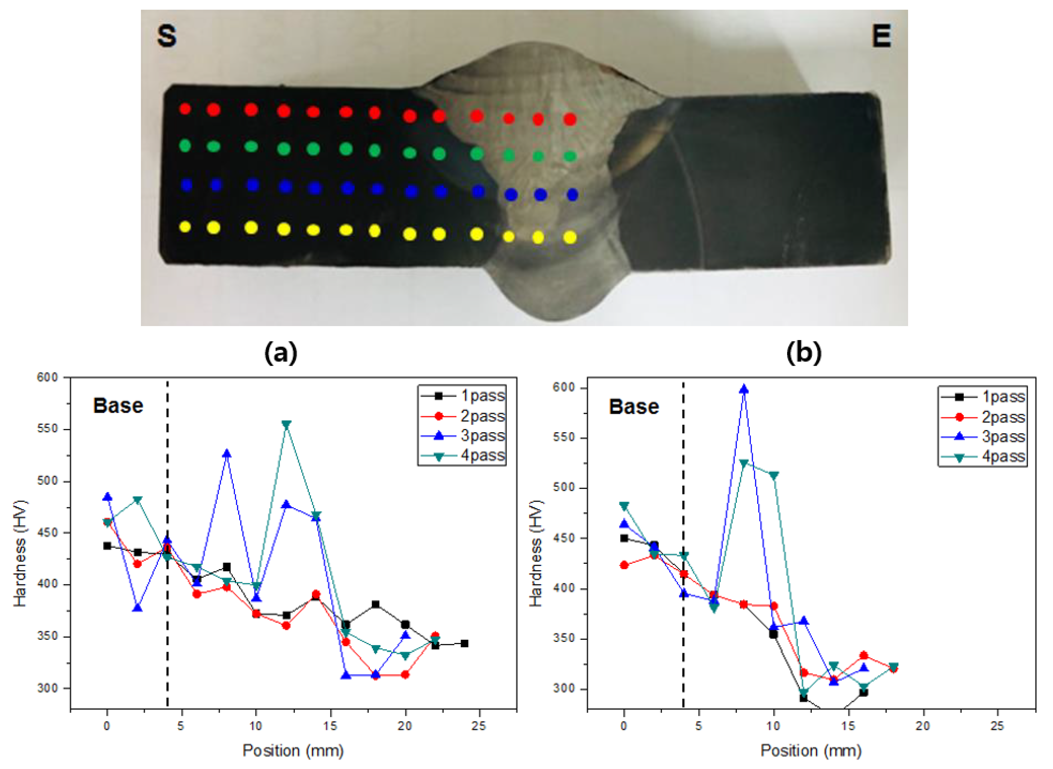
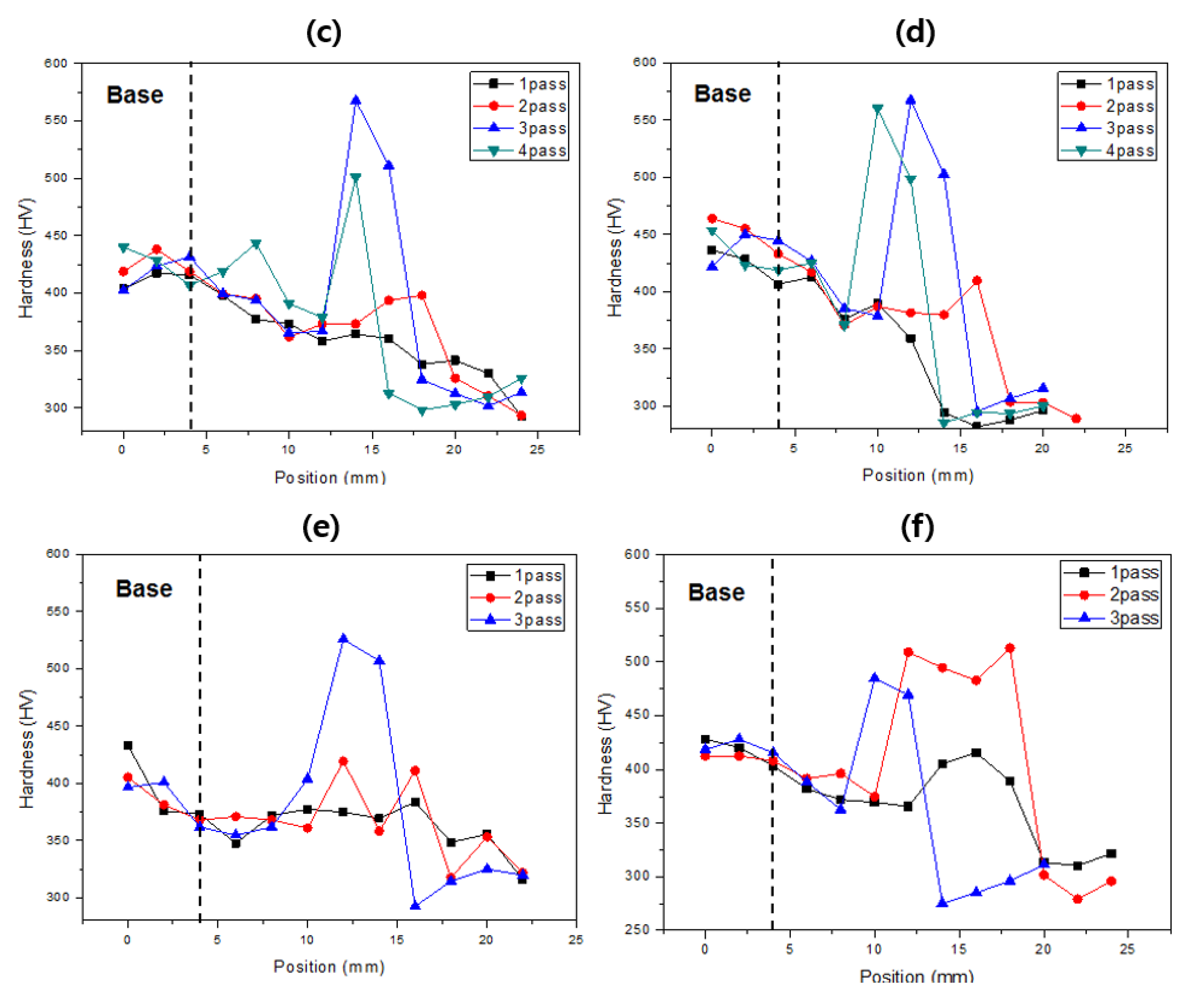
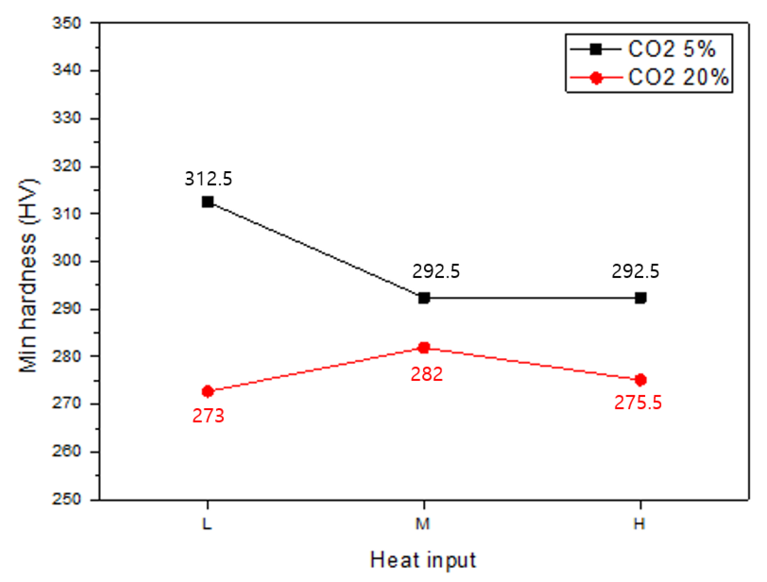
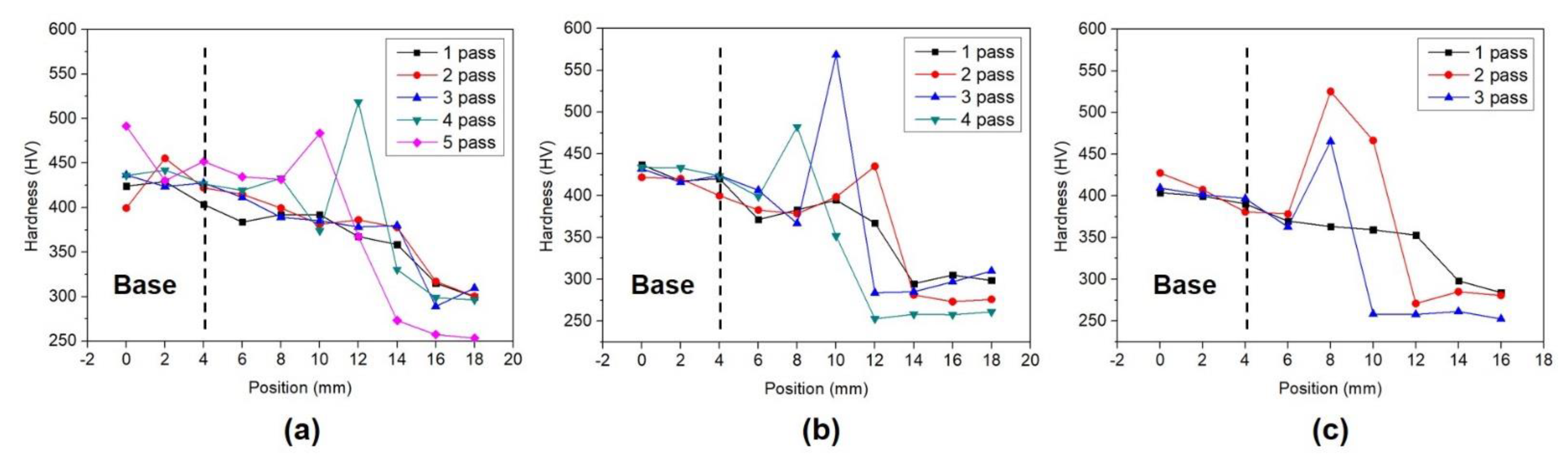
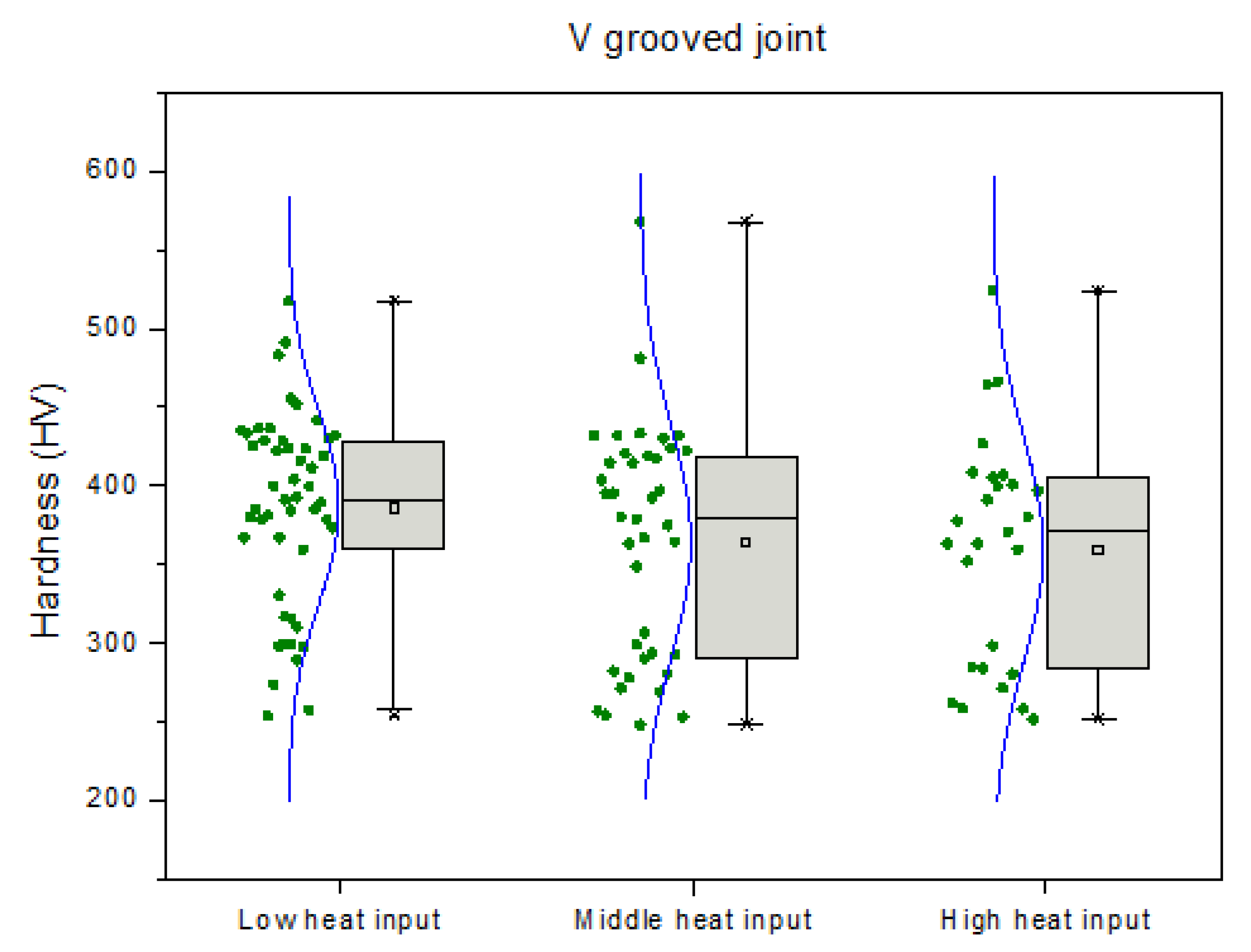
3.2.2. Hardness Analyses Results

The hardness distribution of the specimen was measured according to the amount of shielding gas and heat input. Figure 8 shows the hardness distribution under each condition. It was observed that the hardness of the HAZ tends to increase in all specimens. The hardness of the weld zone was lower than that of the base material and HAZ. The minimum hardness was relatively high in the CO2 5% condition; the minimum hardness tends to decrease as the amount of heat input increases. Figure 9 shows the minimum hardness measurement results for the weld. If the CO2 shielding gas content increases, an arc with more energy is generated, and a high heat input is applied to the welding zone, which increases the cooling time. Owing to the slow cooling rate of the welded zone, a coarse metal structure was generated, and a relatively good hardness value was exhibited under the condition of CO2 5%.
The HAZ’s trend to harden rapidly was reduced because the FCAW method demonstrated slightly lower hardness than the GMAW process. The hardness distribution was similar to that of GMAW. Figure 10 and Figure 11 show that, similar to GMAW, the hardness of the weld decreased as the heat input increased.

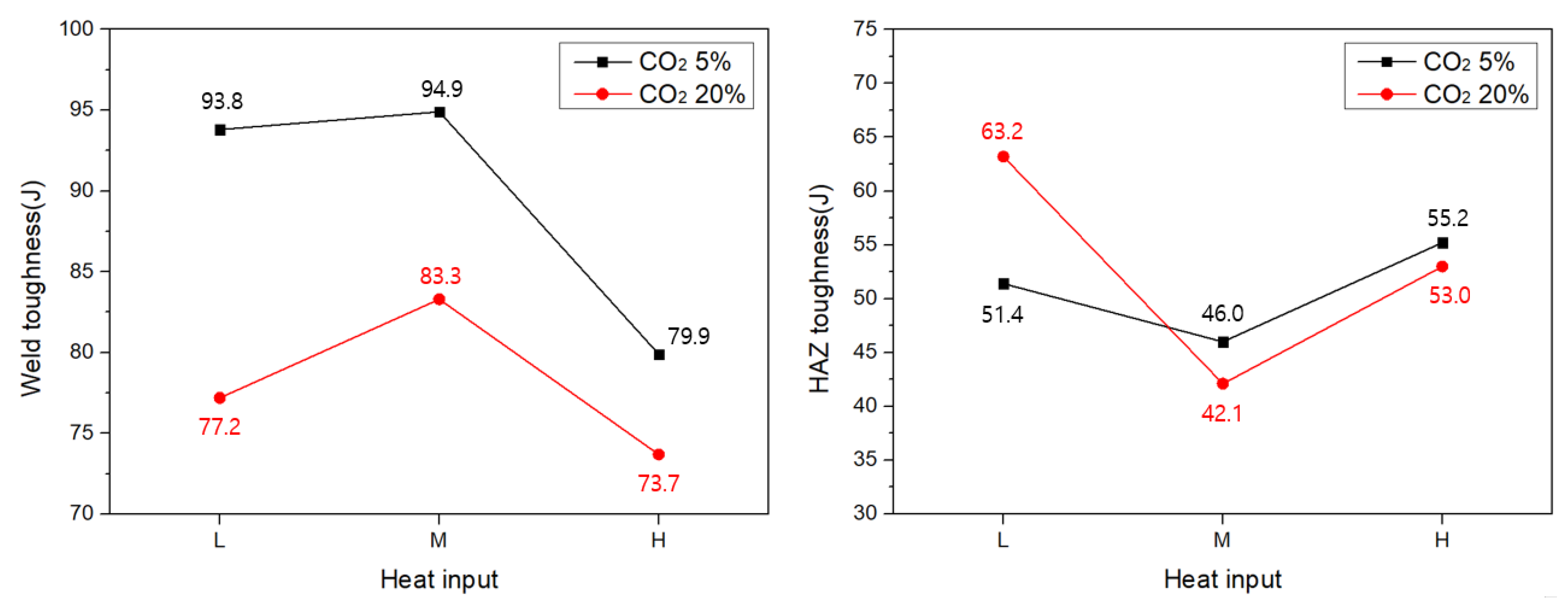
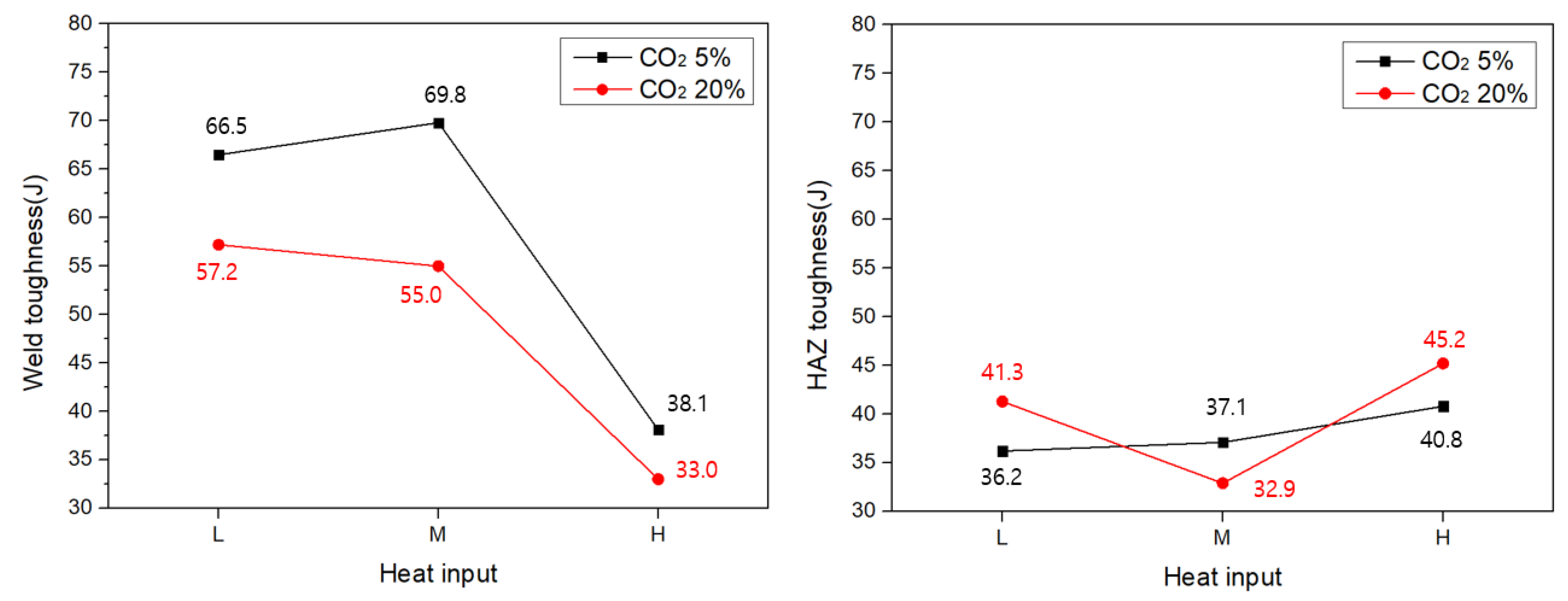
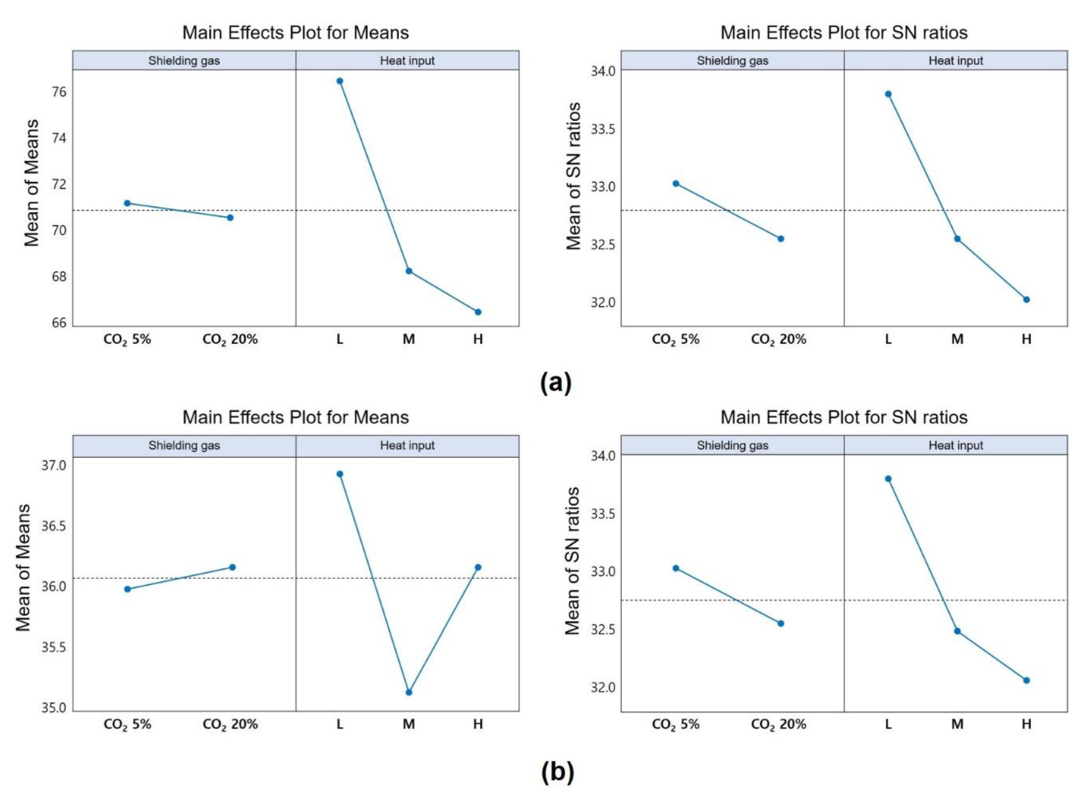
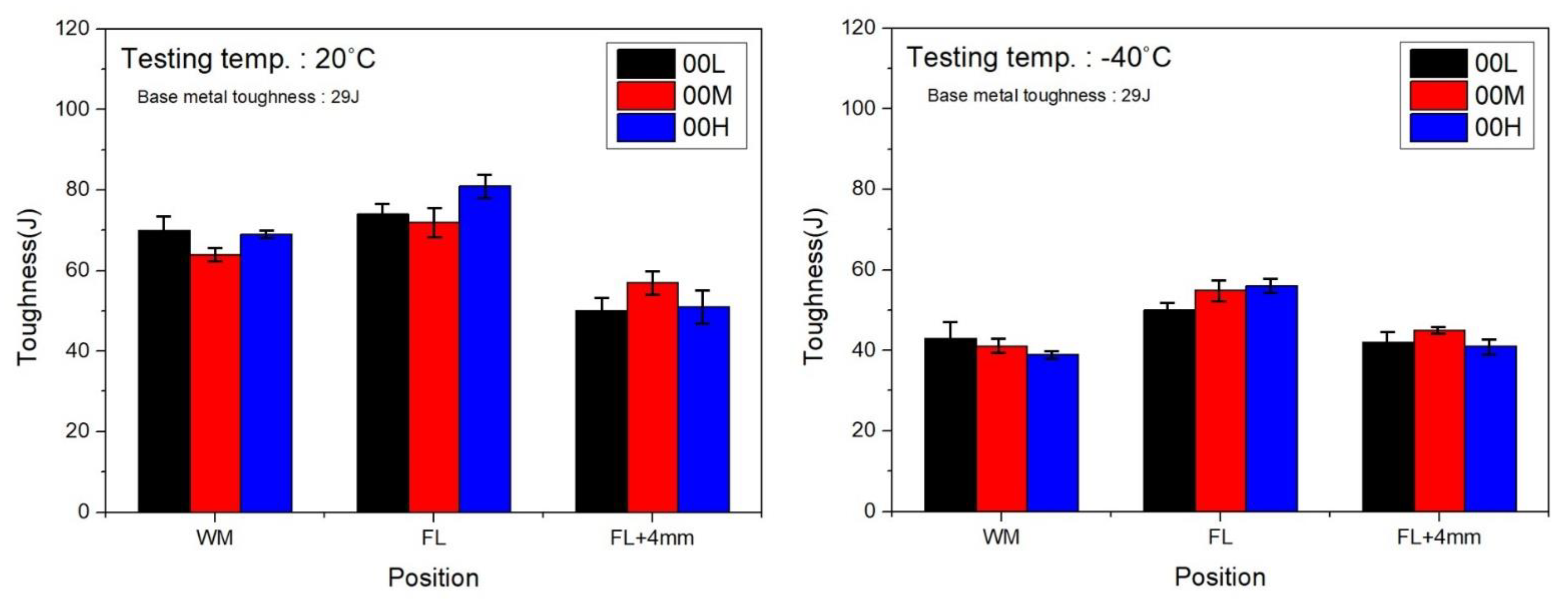
3.2.3. Impact Test Results

Impact tests were carried out based on the amount of shielding gas and heat input. They were performed on the weld zone and affected zone based on the previous hardness distribution results. The heat-affected zone is a softened zone owing to the heat effect of the welding heat source, and the toughness value is highly likely to decrease; therefore, the results were analyzed through an impact test. Figure 12 and Figure 13 show the impact test results at room temperature and in a low-temperature environment, respectively.
As shown in Figure 14, based on the welding impact test results at room temperature (20 °C) and low temperature (−40 °C), the net characteristics of the Taguchi design of experiments (the higher value is the optimal condition) were applied to determine the trend and signal-to-noise (SN) ratio according to the variables. The change in the shielding gas exhibited little change in the shock value. The change in the shock value at room temperature was large when the amount of heat input was changed. Furthermore, under the low heat input condition, a high impact value was confirmed. When the SN ratio was examined, there was no difference in the SN ratio according to the change in the shielding gas, and a high SN ratio was confirmed under the low heat input condition. Because of the low-temperature impact test, it was possible to validate the high impact value under the conditions of 5% CO2 and low heat input. When compared to the impact value at room temperature, the change in the shielding gas showed a large change in impact value. Regarding the SN ratio, a high SN ratio was confirmed under the condition of CO2 5% and low heat input, and the optimal impact value was confirmed under the condition of low heat input CO2 5%. This result has the same cause as the hardness measurement result according to the heat input and CO2 content. The amount of heat input applied to the weld and the degree of coarsening of the metal microstructure affect the cooling rate.
However, the weld area to which FCAW was applied showed a higher average impact result in locations where the mechanical strength decreased, owing to heat softening. Therefore, the overall impact result was somewhat lower than that of GMAW. The FCAW’s impact test results and graphs are shown in Figure 15.

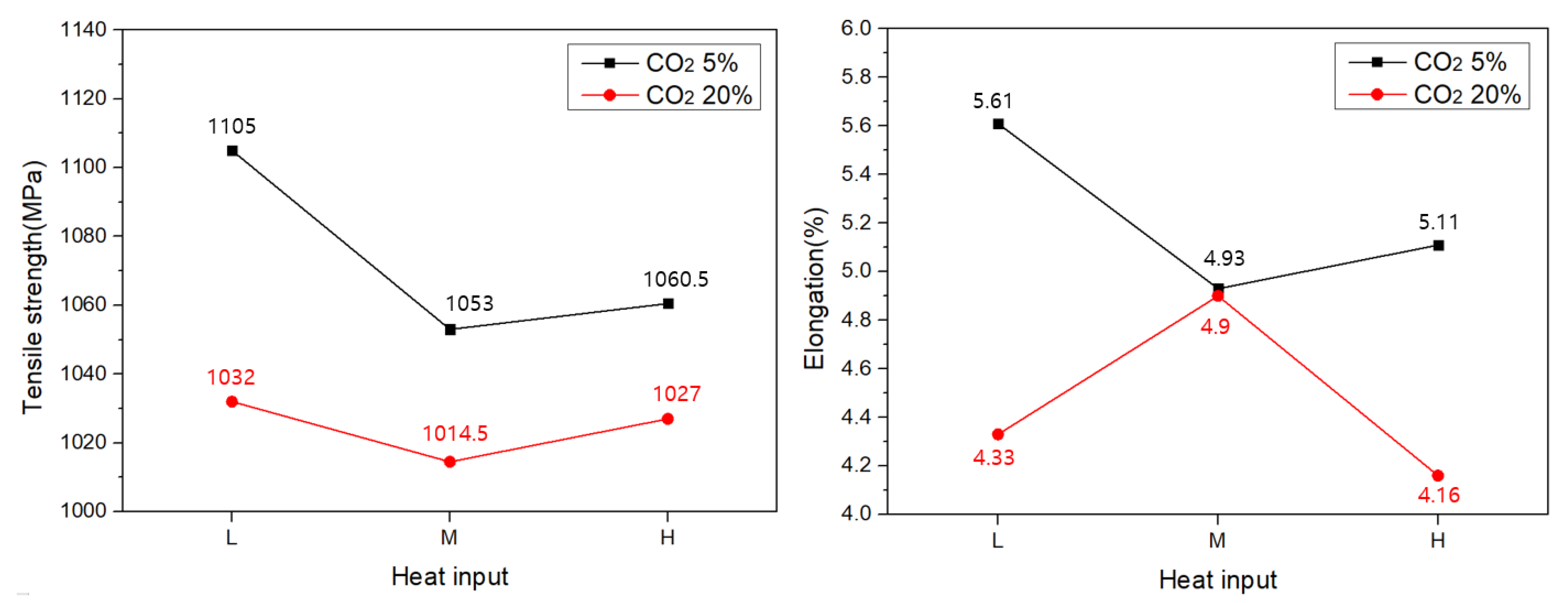
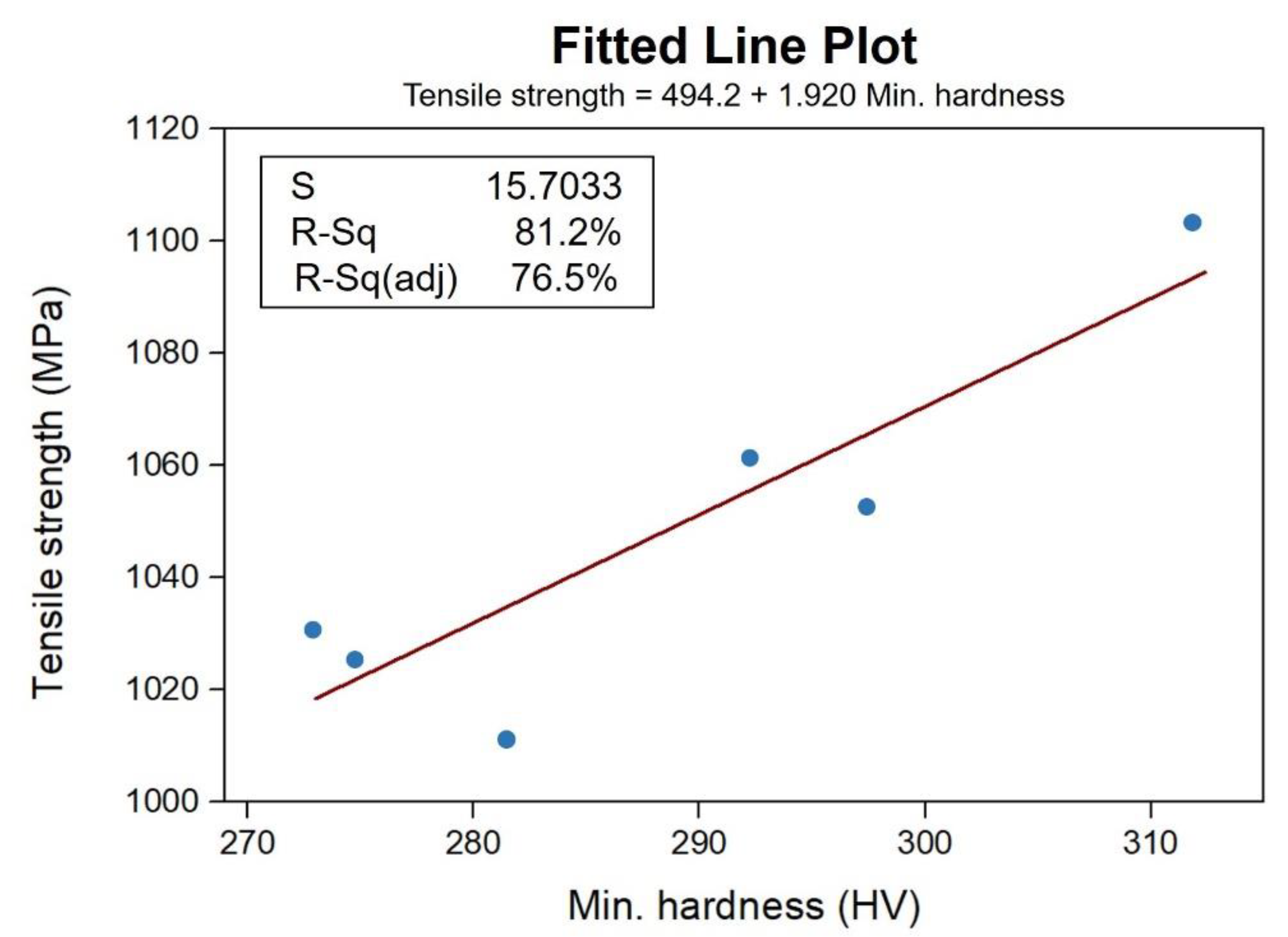
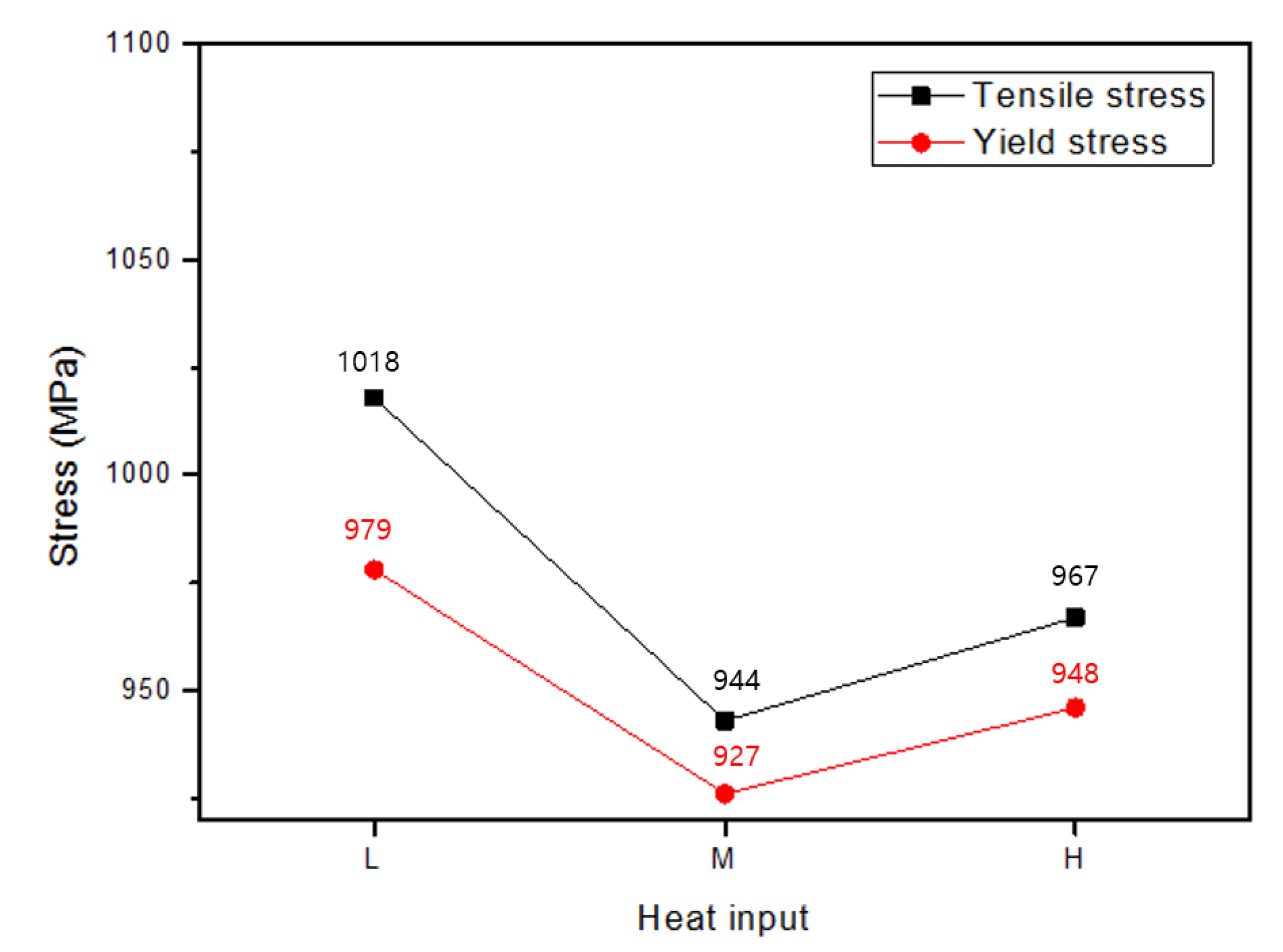
3.2.4. Tensile Test Results

Figure 16 shows the graph of the tensile test results and the resulting values. Usually, under excessive heat input, the mechanical strength of the weld deteriorates, owing to softening and a slow cooling rate. Similarly, in this experiment, it was confirmed that the higher the heat input, the higher the CO2 gas content and the lower the tensile strength. Based on the results of the tensile strength under heat input and shielding gas conditions, the relationship between the minimum hardness and tensile strength was confirmed, as shown in Figure 17, and the results confirmed that the minimum hardness and tensile strength were proportional.
Because of the FCAW tensile test, a higher tensile strength was confirmed compared to that of the applied welding material. Compared to GMAW, the tensile strength was lower, but the elongation was higher. Figure 18 shows the results of the FCAW tensile test. Similar to the tensile strength trend in GMAW, the tensile and yield strengths tended to decrease as the amount of heat input increased.

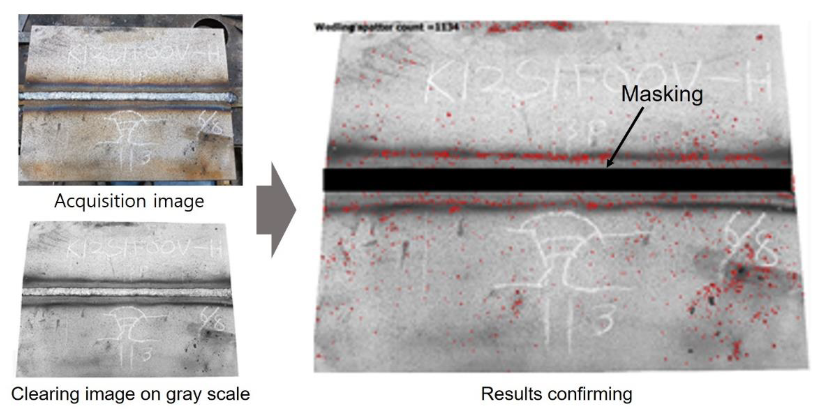
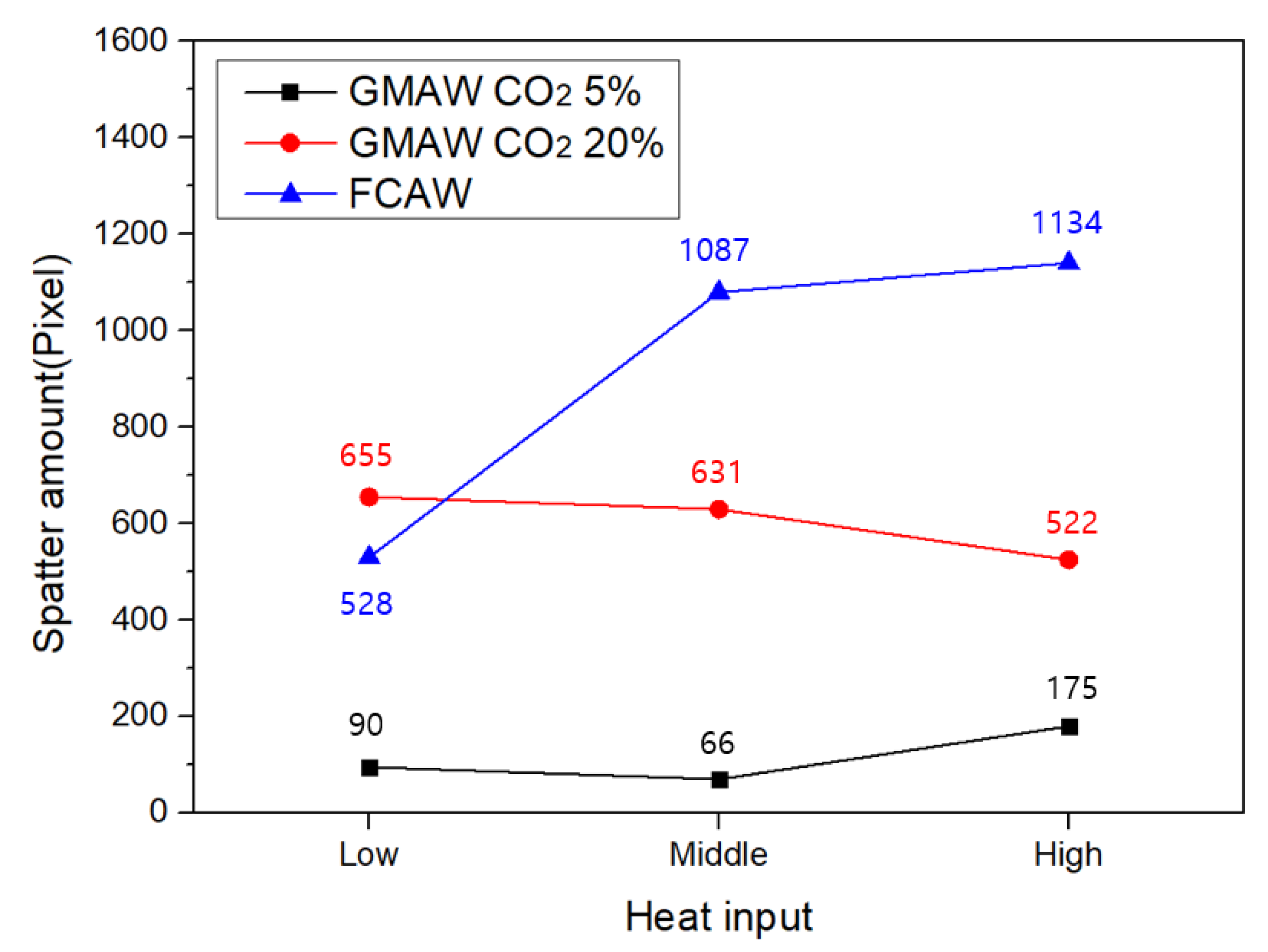
3.3. Weld Spatter Image Analyses

The results show that high mechanical properties were exhibited under low heat input welding conditions using the CO2 5% shielding gas. The soundness of a welded part is an important quality indicator after welding, and the amount of welding spatter is representative. Therefore, spatter image analyses were performed using Labview by taking exterior images of the HHA plates after welding [36,37,38,39]. The image analyses process was performed as shown in Figure 19. A filter is applied to increase the sharpness of the spatter image. The x and y coordinate values of the spatter detected on the filter on the image file were confirmed by the software. The brightness of the spatter image was extracted based on the brightness value, and the extracted spatter was displayed as a red border. As shown in Figure 20, the low heat input welding condition and the shielding gas CO2 5% condition showed the highest surface integrity, and it was confirmed that most of the spatter occurred under the FCAW high heat input condition. The higher the shielding gas content and the higher the heat input, the greater the effect of vaporization and diffusion during the melting of the filler material, resulting in a large number of spatters. In the case of the FCAW process, a large amount of spatter was generated using a welding wire containing flux that generates slag.

4. Conclusions

The mechanical properties and soundness of the welded appearance were investigated to select the type, content, and heat input conditions of single-pulse GMAW shielding gas for HHA plates.
First, the mechanical properties of the weld were analyzed using CO2 5% and O2 2% shielding gas. Cross-sectional analyses of the HHA plate showed no defects at the butt joint. As a result of the impact test, when CO2 5% shielding gas was used, the impact value was relatively improved compared to O2 2%. This is because CO2 creates a narrow and deep arc due to its high energy density. Therefore, the impact value at the fusion line is high because the area affected by heat is relatively small. As a result of the tensile test, the tensile strength was confirmed when 5% CO2 shielding gas was used instead of 2% O2.
An experiment was conducted to determine the gas content and heat input for welding in GMAW and FCAW processes based on CO2 shielding gas. The hardness distribution confirmed that the hardness decreased as the heat input and CO2 content increased. As the heat input and CO2 content increased, a broader and deeper weld bead was formed. As a result of the impact test at room temperature and low temperature, the MIL-DTL-46100E standard was satisfied, and a sufficient toughness value compared to the base material was confirmed. As the heat input and CO2 content increased, the tensile strength and yield strength decreased, and it was confirmed that the minimum hardness and tensile strength results were proportional. A large amount of welding spatter and slag is generated during FCAW, so spatter and slag treatment is essential for each pass. Industrial applications may be limited due to reduced productivity. As a result of image processing used to verify spattering after welding, it was confirmed that low heat input welding using CO2 5% shielding gas showed the highest surface integrity. It was confirmed that spatter occurred the most under the high heat input condition of FCAW. Therefore, welding conditions and bulletproof performance are expected to be improved in the case of a single GMAW of HHA steel.

Author Contributions

Conceptualization, Y.C.J.; Methodology, H.J.S., Y.C.J. and Y.T.C.; Investigation, H.J.S., B.W.S. and Y.-C.K.; Writing—original draft preparation, H.J.S., Y.C.J., B.W.S., S.-T.H., Y.-C.K. and Y.T.C.; Writing—review and editing, H.J.S., Y.C.J. and Y.T.C.; Visualization, H.J.S., B.W.S. and S.-T.H.; Supervision, Y.T.C.; Project administration, Y.T.C. All authors have read and agreed to the published version of the manuscript.

Funding

This research was supported by “Regional Innovation Strategy (RIS)” through the National Research Foundation of Korea (NRF) funded by the Ministry of Education (MOE) (2023RIS-003). This work was supported by the National Research Foundation of Korea (NRF) grant funded by the Korea government (MSIT) (No. 2019R1A5A8083201).

Data Availability Statement

Not applicable.

Acknowledgments

This research was supported by “Regional Innovation Strategy (RIS)” through the National Research Foundation of Korea (NRF) funded by the Ministry of Education (MOE) (grant no. 2023RIS-003). This work was supported by the National Research Foundation of Korea (NRF) grant funded by the Korea government (MSIT) (grant no. 2019R1A5A8083201).

Conflicts of Interest

The authors declare no conflict of interest.

References

  1. Zhou, W.; Cleaver, C.J.; Dunant, C.F.; Allwood, J.M.; Lin, J. Cost, range anxiety and future electricity supply: A review of how today’s technology trends may influence the future uptake of BEVs. Renew. Sustain. Energy Rev. 2022, 173, 113074. [Google Scholar] [CrossRef]
  2. Joost, W.J. Reducing Vehicle Weight and Improving, U.S. Energy Efficiency Using Integrated Computational Materials Engineering. JOM 2012, 64, 1032–1038. [Google Scholar] [CrossRef]
  3. Prifti, J.J.; Squillacioti, R.; Cellitti, R. Improved Rolled Homogeneous Armor (IRHA) Steel Through Higher Hardness; United States Army Research Laboratory: Adelphi, MD, USA, 1997. [Google Scholar]
  4. Jeong, Y.; Kim, C.; Lee, S.; Jung, Y.; Park, C.; Lee, B.; Park, T.; Kim, H.; Cho, Y.T. Welding technical trend of high hardness armour steel for combat vehicle. J. Korea Inst. Mil. Sci. Technol. 2019, 22, 299–310. [Google Scholar] [CrossRef]
  5. Balakrishnan, M.; Balasubramanian, V.; Madhusuhan Reddy, G.M.; Sivakumar, K. Effect of buttering and hardfacing on ballistic performance of shielded metal arc welded armour steel joints. Mater. Des. 2011, 32, 469–479. [Google Scholar] [CrossRef]
  6. Cho, H.H.; Shin, Y.C.; Yi, H.J. STUD welding on high hardness armor steel of KWV. J. Korea Inst. Mil. Sci. Technol. 2016, 19, 567–573. [Google Scholar] [CrossRef]
  7. Lim, H.S.; Lee, J.M.; Song, Y.B.; Kim, H.K.; Hwang, B.C. Effect of tempering temperature on the microstructure and mechanical properties of ARMOX 500T armor plate. Korean J. Mater. Res. 2017, 27, 357–361. [Google Scholar]
  8. Robledo, D.M.; Gomez, J.A.S.; Barrada, J.E.G. Development of a welding procedure for MIL A 46100 armor steel joints using gas metal arc welding. Dyna 2011, 78, 65–71. [Google Scholar]
  9. Kuzemikova, L. An Investigation of the Weldability of High Hardness Armour Steels. Ph.D. Thesis, University of Wollongong, Wollongong, Australia, 2013. [Google Scholar]
  10. Gedeon, S.A.; Catalano, J.E. Reduction of M1 Weld Fabrication Costs: The Effect of Weld Shielding Gas Composition; US Army Material Technology Lab: Watertown, MA, USA, 1998.
  11. Madhusudhan Reddy, G.M.; Mohandas, T.; Papukutty, K.K. Effect of welding process on the ballistic performance of high-strength low-alloy steel weldments. J. Mater. Process. Technol. 1998, 74, 27–35. [Google Scholar] [CrossRef]
  12. Alkemade, S.J. The Weld Cracking Susceptibility of High Hardness Armour Steel; Defence Science and Technology Organization: Sydney, Australia, 1996; p. 24.
  13. Arif, N.; Chung, H. Alternating current-gas metal arc welding for application to thick plates. J. Mater. Process. Technol. 2015, 222, 75–83. [Google Scholar] [CrossRef]
  14. Bai, X.; Zhang, H.; Wang, G. Modeling of the moving induction heating used as secondary heat source in weld-based additive manufacturing. Int. J. Adv. Manuf. Technol. 2015, 77, 717–727. [Google Scholar] [CrossRef]
  15. Magudeeswaran, G.; Balasubramanian, V.; Madhusudhanreddy, G.M. Hydrogen induced cold cracking studies on armour grade high strength, quenched and tempered steel weldments. Int. J. Hydrog. Energy. 2008, 33, 1897–1908. [Google Scholar] [CrossRef]
  16. Magudeeswaran, G.; Balasubramanian, V.; Reddy, G.M.; Balasubramanian, T.S. Effect of welding processes and consumables on tensile and impact properties of high strength quenched and tempered steel joints. J. Iron Steel Res. Int. 2008, 15, 87–94. [Google Scholar] [CrossRef]
  17. Magudeeswaran, G.; Balasubramanian, V.; Madhusudhan Reddy, G.M. Effect of welding processes and consumables on high cycle fatigue life of high strength, quenched and tempered steel joints. Mater. Des. 2008, 29, 1821–1827. [Google Scholar] [CrossRef]
  18. Kwak, Y.; Lee, S.H.; Kang, M. Effects of Shielding Gases on the Weldability of Laser Welded Austenitic Stainless Steel. J. Weld. Join. 2022, 40, 525–532. [Google Scholar] [CrossRef]
  19. Cui, S.; Pang, S.; Pang, D.; Tian, F.; Yu, Y. The Microstructure and Pitting Corrosion Behavior of K-TIG Welded Joints of the UNS S32101 Duplex Stainless Steel. Materials 2023, 16, 250. [Google Scholar] [CrossRef]
  20. Veiga, F.; Suarez, A.; Aldalur, E.; Artaza, T. Wire arc additive manufacturing of invar parts: Bead geometry and melt pool monitoring. J. Meas. 2022, 189, 110452. [Google Scholar] [CrossRef]
  21. Dinovitzer, M.; Chen, X.; Laliberte, J.; Huang, X.; Frei, H. Effect of wire and arc additive manufacturing (WAAM) process parameters on bead geometry and microstructure. Addit. Manuf. 2019, 26, 138–146. [Google Scholar] [CrossRef]
  22. Srivastavva, S.; Garg, R.K.; Sachdeva, A.; Sharma, V.S. Distribution of Residual Stress in Wire-Arc Additively Manufactured Small-Scale Component: Single- Versus Multi-Level Heat Input. J. Manuf. Sci. Eng. 2022, 145, 021008. [Google Scholar] [CrossRef]
  23. Seo, B.W.; Kim, D.-Y.; Kim, C.; Kim, S.; Cho, Y.T. Development of seam tracking device in asynchronous tandem welding with arc sensing. Sci. Rep. 2022, 12, 18637. [Google Scholar] [CrossRef]
  24. Garzon, C.M.; Giraldo, J.E. Numerical and experimental analysis of microstructure evolution during arc welding in armor plate steels. J. Mater. Process. Technol. 2009, 209, 1688–1700. [Google Scholar] [CrossRef]
  25. Cabrilo, A.; Geric, K.; Jovanovic, M.; Vukic, L. Weldability and impact energy properties of high-hardness armor steel. J. Mater. Eng. Perform. 2018, 27, 1281–1295. [Google Scholar] [CrossRef]
  26. Bassett, J. Laser welding of high hardness armour steel. Sci. Technol. Weld. Join. 1998, 3, 244–248. [Google Scholar] [CrossRef]
  27. Naveen Kumar, S.; Balasubramanian, V.; Malarvizhi, S.; Hafeezur Rahman, A.; Balaguru, V. Influence of microstructural characteristics on ballistic performance and its mode of failure in shielded metal arc welded ultra-high hard armor steel joints. Trans. Indian Inst. Met. 2021, 74, 909–921. [Google Scholar] [CrossRef]
  28. US Department of Defense. MIL-A-12560H—Armor Plate, Steel, Wrought, Homogeneous; US Department of Defense: Washington, DC, USA, 1990.
  29. US Department of Defense. MIL-A-46100D—Armor Plate, Steel, Wrought, High Hardness; US Department of Defense: Washington, DC, USA, 1988.
  30. Australian Department of Defence Australian Defence Standard: Discovery Eye Foundation: Australia 8030, Rolled Armour Plate, Steel (3–35 mm); Australian Department of Defence: Canberra, Australia, 2005.
  31. UK Ministry of Defence. UK Defence Standard, DEF STAN 95–24, Armour Plate, Steel (3–160 mm); UK Ministry of Defence: London, UK, 2004.
  32. US Army Tank-Automotive and Armaments Command. Tacom Drawing 12479550, Ground Combat Vehicle Welding Code-Steel; US Army Tank-Automotive and Armaments Command: Warren, MI, USA, 2006. [Google Scholar]
  33. Pickin, C.G.; Williams, S.W.; Lunt, M. Characterisation of the cold metal transfer (CMT) process and its application for low dilution cladding. J. Mater. Process. Technol. 2011, 211, 496–502. [Google Scholar] [CrossRef]
  34. Schieril, A. The CMT process a revolution in welding technology. Weld. Word. 2005, 49, 38. [Google Scholar]
  35. Azar, A.S. A heat source model for cold metal transfer (CMT) welding. J. Therm. Anal. Calorim. 2015, 122, 741–746. [Google Scholar] [CrossRef]
  36. Schweier, M.; Heins, J.F.; Haubold, M.W.; Zaeh, M.F. Spatter formation in laser welding with beam oscillation. Phys. Procedia 2013, 41, 20–30. [Google Scholar] [CrossRef]
  37. Ersoy, U.; Hu, S.J.; Kannatey-Asibu, E. Observation of arc start instability and spatter generation in GMAW. Weld. Res. 2008, 4, 51–56. [Google Scholar]
  38. Era, T.; Ueyama, T. Spatter reduction in GMAW by current waveform control. Weld Int. 2007, 21, 496–501. [Google Scholar] [CrossRef]
  39. Tan, Z.; Fang, Q.; Li, H.; Liu, S.; Zhu, W.; Yang, D. Neural network based image segmentation for spatter extraction during laser-based powder bed fusion processing. Opt. Laser Technol. 2020, 130, 106347. [Google Scholar] [CrossRef]
Figure 1. Specimen dimensions.
Metals 13 00303 g001
Figure 2. Hardness test results in butt joint with variation of shielding gas: (a) O2 2%, 14.0~15.5 kJ/cm; (b) CO2 5%, 12.8~17.7 kJ/cm.
Metals 13 00303 g002
Figure 3. Hardness test results with variation of shielding gas.
Metals 13 00303 g003
Figure 4. Toughness results of HHA1 butt joints at room temperature (20 °C) and low temperature (−40 °C).
Metals 13 00303 g004
Figure 5. Tensile test results in HHA1 butt joint with O2 and CO2 gas.
Metals 13 00303 g005
Figure 6. Cross-sectional view analysis of GMAW with CO2 5% and 20% shielding gas and heat input in butt joint (a) 05L; (b) 05M; (c) 05H; (d) 20L; (e) 20M; (f) 20H.
Metals 13 00303 g006
Figure 7. Sectional view analyses of FCAW weld with CO2 5% and 20% shielding gas and heat input in butt joint: (a) 00L; (b) 00M; (c) 00H.
Metals 13 00303 g007
Figure 8. Hardness analyses of GMAW with CO2 5% and 20% shielding gas and heat input in butt joint: (a) 05L; (b) 20L; (c) 05M; (d) 20M; (e) 05H; (f) 50H.
Metals 13 00303 g008aMetals 13 00303 g008b
Figure 9. Minimum hardness analyses of GMAW with CO2 5% and 20% shielding gas and heat input in weldment.
Metals 13 00303 g009
Figure 10. Hardness analyses results of FCAW weld with CO2 5% and 20% shielding gas and heat input: (a) 00L; (b) 00M; (c) 00H.
Metals 13 00303 g010
Figure 11. Hardness analyses results of FCAW with heat input in butt joint.
Metals 13 00303 g011
Figure 12. Toughness results of GMAW with CO2 5% and 20% shielding gas and heat input at room temperature (20 °C).
Metals 13 00303 g012
Figure 13. Toughness results of GMAW with CO2 5% and 20% shielding gas and heat input at low temperature (−40 °C).
Metals 13 00303 g013
Figure 14. Taguchi results of GMAW with CO2 5% and 20% shielding gas and heat input: (a) Room temperature (20 °C); (b) Low temperature (−40 °C).
Metals 13 00303 g014
Figure 15. Toughness results of FCAW with CO2 5% and 20% shielding gas and heat input at room temperature (20 °C) and low temperature (−40 °C).
Metals 13 00303 g015
Figure 16. Tensile test results of GMAW with CO2 5% and 20% shielding gas and heat input.
Metals 13 00303 g016
Figure 17. Relation between tensile strength and min hardness results of GMAW.
Metals 13 00303 g017
Figure 18. Tensile test results of FCAW with CO2 100% shielding gas and heat input.
Metals 13 00303 g018
Figure 19. Weld spatter image analyses and image processing.
Metals 13 00303 g019
Figure 20. Results of image-processed welding spatter.
Metals 13 00303 g020
Table 1. Mechanical properties of solid and flux cored wire.
Solid WireFlux Cored Wire
Tensile strength (MPa)830864
Elongation (%)1219
Table 2. Chemical properties of solid and flux cored wire (wt%).
CMnSiNiMoSP
Solid wire0.061.480.0033.420.570.0030.002
Flux cored wire0.031.690.392.660.670.0060.010
Table 3. Welding condition for determination of shielding gas.
Welding
Mode
Shielding GasJointHeat Input
(kJ/cm)
GMAW
(3pass)
Ar 98% + O2 2%Butt14.0~15.5
Ar 95% + CO2 5%Butt12.8~17.7
Table 4. Welding conditions for heat input and shielding gas composition.
Welding
Mode
Shielding GasJointHeat Input
(kJ/cm)
Specimen
Name
Pass
GMAWAr 95% + CO2 5%ButtL11.1~12.605L4
M13.3~16.905M4
H19.2~20.605H3
Ar 80% + CO2 20%ButtL10.6~13.620L4
M14.2~16.820M4
H17.6~20.620H3
FCAWCO2 100%ButtL10.0~13.000L5
M15.1~16.700M4
H17.4~19.300H3
Disclaimer/Publisher’s Note: The statements, opinions and data contained in all publications are solely those of the individual author(s) and contributor(s) and not of MDPI and/or the editor(s). MDPI and/or the editor(s) disclaim responsibility for any injury to people or property resulting from any ideas, methods, instructions or products referred to in the content.

