Review

A Review of Top-Submerged Lance (TSL) Processing—Part I: Plant and Reactor Engineering

1
TU Bergakademie Freiberg, Institute of Nonferrous Metallurgy and Purest Materials (INEMET), Leipziger Straße 34, 09599 Freiberg, Germany
2
Department of Engineering Technology and Didactics, DTU Engineering Technology, Technical University of Denmark, Lautrupvang 15, 2750 Ballerup, Denmark
3
TU Bergakademie Freiberg, Institute of Energy Process Engineering and Chemical Engineering (IEC), Reiche Zeche, Fuchsmühlenweg 9 D, 09599 Freiberg, Germany
*
Author to whom correspondence should be addressed.
Metals 2023, 13(10), 1728; https://doi.org/10.3390/met13101728
Submission received: 31 July 2023 / Revised: 9 September 2023 / Accepted: 14 September 2023 / Published: 12 October 2023
(This article belongs to the Special Issue Metal Extraction/Refining and Product Development)

Abstract

:
Part I of this series of papers focuses on plant and reactor engineering aspects of the TSL reactor technology. A general flowsheet is presented, while emphasis is given to the definition of different reactor zones in terms of fluid dynamics and occurring reactions. Then, the technical advantages of TSL processing, such as feed flexibility and high conversion rates (due to induced turbulence), low dust generation, and low fugitive emissions, are explained. In addition, the reactor is analyzed part by part, also taking into account patent literature, focusing on furnace design, settling furnaces for molten phase disengagement, feeding systems regarding input material streams such as concentrates and fuels, vessel cooling arrangements, off-gas system, and aspects associated with the refractory lining. Furthermore, specific focus is given to the centerpiece of the TSL reactor, i.e., the reactor lance. Associated developments have focused on establishing a slag coating to hinder lance wear, i.e., the development of cooling mechanisms (e.g., use of fluid-cooled lance and shroud arrangements), the increment of O2 enrichment within the incoming air stream, and influencing of fluid dynamics (e.g., O2 conversion at the lance tip, bubble formation, and bath splashing). Finally, comprehensive tables concerning process developments and commissioned TSL plants are provided thus concluding Part I of the review.

1. Introduction

Smelting refers to the extraction of metals from a concentrate by a process involving heating and melting. The word is etymologically related to the German word “Schmelzen” [1]. Different mechanisms such as oxidation or reduction can occur regarding the material of interest. The goal is to extract the desired metal from the primary or secondary material. During the process, the unwanted/rejected materials can segregate and form slag. On the other hand, some species may be highly volatile, i.e., exhibit a low boiling point and high vapor pressure, thus escaping the reactor via the gas phase. The primary goal is to recover as many of the materials of value as possible during the smelting process. The furnaces utilized to carry out the metal extraction require different temperature levels and oxidizing or reducing atmospheres. The latter two variables are used for “process mapping”, as shown in Figure 1.
The name “TSL” itself explains that the furnace consists of a lance immersed in the slag from the top of the furnace. J.M. Floyd invented the TSL technology in 1970 at CSIRO in Australia. Initially, it was named “high-temperature submerged combustion,” then SIROSMELT. This technology was later distributed to other license holders in the 1990s, making it global. From a reactor engineering perspective, TSL processing has distinct differences in comparison to other smelting furnaces. For example, a key component for a flash smelter is the concentrate burner which brings into contact dried concentrate to be oxidized with oxygen-enriched air. Furthermore, tuyere furnaces rely on a series of discrete nozzles in typically horizontal furnaces, like the Noranda-Teniente furnace. On the other hand, for overhead lance injection processes such as the Mitsubishi process, no submersion of the lance occurs. The TSL reactor is vertical and relies on an efficient lance design for gas and/or fine particle injection combined with overhead feeding. The lance is immersed in the bath and blows within the slag phase. When taking into account copper matte smelting, these different reactor engineering arrangements lead to distinct reaction mechanisms and fluid dynamics. Hence, for copper flash smelting, matte-slag formation reactions occur in flight. For Noranda-Teniente furnaces the oxygen-enriched air is blown to the matte phase leading to direct matte oxidation [3]. Within the TSL reactor oxidation processes often occur indirectly. In the case of copper matte smelting, matte oxidation proceeds through the slag component Fe2O3/dissolved magnetite. Upon matte oxidation, Fe+3 is reduced to Fe+2 within the slag, while Fe+3 is regenerated through the interaction of the slag with gaseous oxygen originating from the lance. The contact between the slag and matte phase is crucial here and is assured by the turbulence induced by gas injection with the use of the submerged lance. TSL reactor-associated processing mechanisms are discussed in Part II of this series of papers.
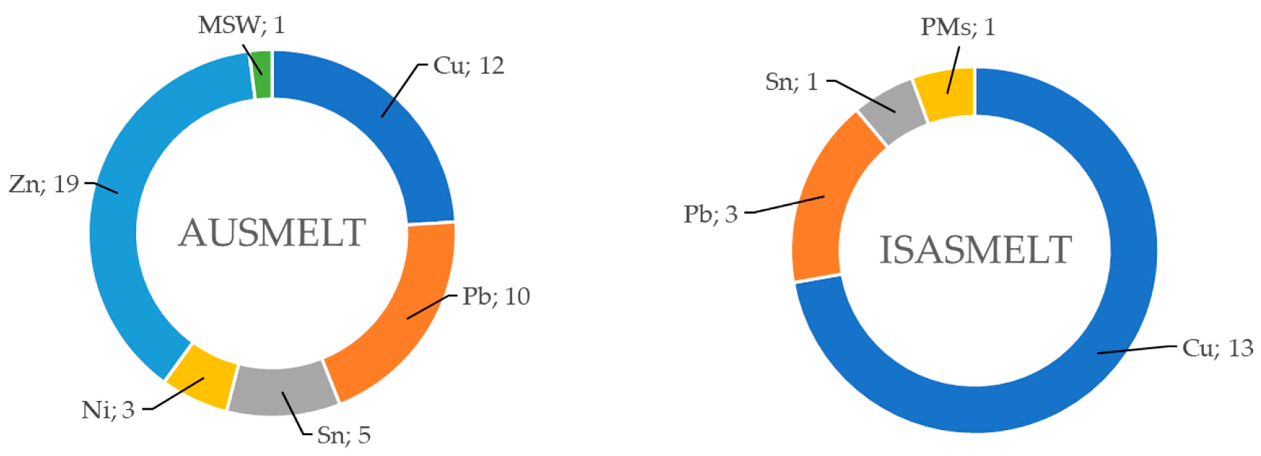
Currently, there are two major license holders for TSL technology:
  • Metso: AUSMELT technology (Note: Metso Corporation and Outotec merged in June 2020 and formed Metso. The new name (Metso) is therefore used throughout this article).
  • Glencore: ISASMELT technology (Note: Glencore acquired Xstrata in May 2013).
A layout of a TSL plant and a block diagram including concentrate blending, oxygen plant, heat recovery, an ESF for matte/slag settling/separation, and off-gas streamflow are shown in Figure 2.
TSL is a bath smelting technology with a vertical cylindrical furnace and a central lance injecting fuel and air (oxygen-enriched, up to and in some cases exceeding 80%) into the slag bath [5]. The limitation of oxygen enrichment is that nitrogen is required to transfer sufficient momentum to splash the slag (as a mass transfer carrier). The lance can be operated under oxidizing, neutral, or reducing conditions by setting the λ value to control the slag chemistry at the lance tip and gas-rise region of the slag bath. This is true since the λ value directly relates to the global PO2 within the vessel, the latter being further influenced by the feed rate of reductants (e.g., coal) and further feed materials (that can react to consume oxygen) such as sulfide concentrates [5]. During its operation, the lance is covered by a solidified slag layer caused by splashing in the furnace, which protects the lance from rapid corrosion. This coating is caused by local cooling of the slag due to the gas flow occurring within the lance. As a result, the slag becomes saturated with magnetite in the vicinity of the lance, which leads to a magnetite layer solidifying on the lance surface. The depth of lance penetration into the slag depends on the application (typically 800–2000 mm in an industrial-scale TSL) [
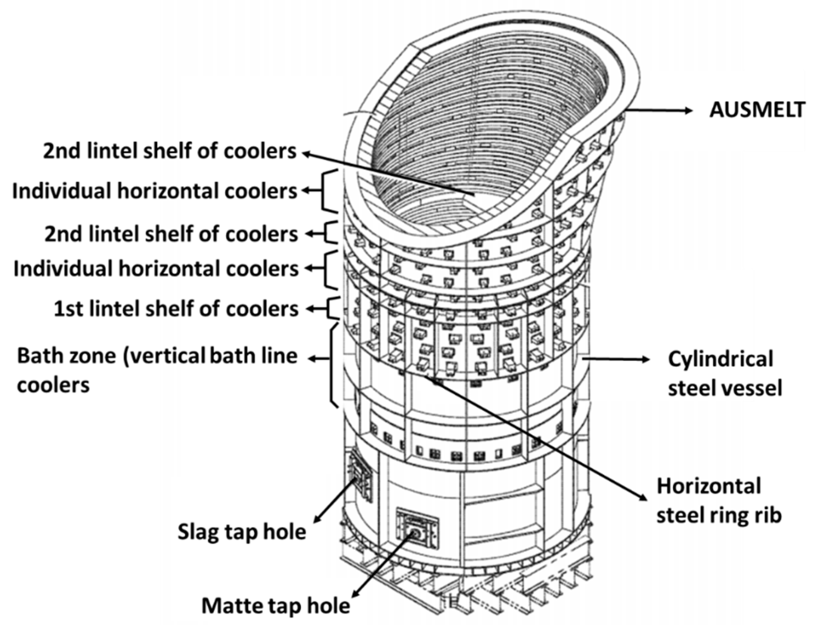
6]. A schematic representation of the two TSL furnace designs is shown in Figure 3.
For continuous smelting and converting operations employing TSL technology, AUSMELT and ISASMELT use ESFs [9] and RHFs [10], respectively. These furnaces “separate” matte from slag and act as a holding vessel in the case of continuous operation upstream (e.g., copper concentrate smelting) and batch operation downstream (e.g., matte converting). AUSMELT uses an “underflow weir”, which allows the molten bath to flow continuously to the ESF or further downstream unit operation via the weir spout (overflow). Elaborating further regarding the weir, burner ports are implemented within the hood (roof), and the design also utilizes cooling elements and a pyrometer (monitoring tapping temperatures). This method allows the molten bath to flow without the need for classical tapping and associated disadvantages (e.g., use of a mud gun and drilling operations). Using a weir, the bath level can be kept constant since the operation is based on the overflow principle. A few disadvantages associated with using a weir could be due to solidified slag freeze within the weir ports (during matte/bullion tapping) and more refractory wear at the bath level (i.e., due to stable bath height, the effect of splashing and turbulence is concentrated at the bath surface peripheral). More than 35 AUSMELT TSL reactors are equipped with a weir in various smelting applications associated with copper, lead, and zinc residue smelting operations [11]. One example of an ESF has been shown to be rectangular and consisting of several electrodes [9]. On the other hand, ISASMELT typically taps out to settling furnaces intermittently or continuously through a water-cooled taphole using semi-automated mechanical equipment [12]. The latter may be of the RHF type, i.e., cylindrical in shape. RHFs are refractory lined and equipped with burner ports to maintain the temperature [10]. As mentioned in the same reference, the RHF can be tilted to enable matte and slag to discharge at appropriate locations. Pictures of a weir and rotary furnace before and upon installation are shown in Figure 4 and Figure 5, respectively.
An example of a general TSL process flowsheet is shown in Figure 6, where numerous TSL (AUSMELT) reactors are used to treat zinc residues at Korea Zinc, South Korea (>1 million tpa feed throughput). This flowsheet can be employed to treat and recover valuable metals from zinc residues and various other zinc-bearing materials. The process achieves high recovery rates of Zn, Pb, Cd, In, Ge, Au, and Ag, among other elements, which report to the fumes emitted while producing a slag that meets TCLP requirements. As proven by Korea Zinc, the benign slag produced can be safely discarded or used as a construction material [13].
Considering digitization and process logic controls for TSL operation, AUSMELT industrial plants use Metso’s ACT platform to monitor and forecast its TSL operations. The ACT platform can be coupled with the HSC Chemistry and HSC SIM module (flowsheet modeling), which helps estimate the process efficiency, yield, and environmental footprints. On the other hand, Glencore uses two control platform providers, namely Yokogawa (which contains various DCSs, SIS, PLCs, and RTU) and Emerson (DeltaVTM) for their ISASMELT operations [14,15].

2. TSL Technology Application to the Production of Metals

Due to its high flexibility (as discussed in the above sections), a wide range of metals have been extracted using TSL technology. For example, TSL plants are associated mainly with the primary and secondary metallurgy of tin, copper, lead, zinc, nickel, and PGMs. Zinc recovery is mainly associated with the treatment of residues, while PGM recovery is widely related to WEEE feed and is combined with the secondary metallurgy of copper or lead (exceptions are primary PGM production facilities like ACP in South Africa). The statistical data (from 2023) shown in Figure 7, Table 1 and Figure 8 are presented for the two major license holders (Metso and Glencore). The above two companies have a combined market of more than 98% of global TSL technology [6,16,17,18]. Both Figure 7 and Figure 8 show clearly, both in terms of feed throughput capacity and installed units, that applications associated with Cu have been dominant, followed by those associated with Pb and Zn. It should be noted that the mentioned feed throughput per annum in Figure 8 represents the TSL capacity during commissioning, which later would have been modified by the client. All TSL installations by Metso and Glencore are shown in the Appendix A. There are various smaller TSL applications in addition to those installed by Metso and Glencore. An example is a smaller industrial TSL, smelting e-waste by Shan Poornam Metals (https://shanpoornammetals.com/) (accessed on 30 July 2023), Malaysia which processes 4000 tpa of e-waste. This is a reference by SMS GmbH, Germany (https://www.sms-group.com/de-de) (accessed on 30 July 2023). Further companies, such as Hatch Küttner (https://www.kuettner.com/en/about-us) (accessed on 30 July 2023) offer TSL furnaces in their portfolio.

3. TSL Technology

In this section, some of the pilot-scale TSL facilities around the world are shown in Table 2 to provide an understanding of their scale and auxiliaries. However, pilot TSL plants from CSIRO (Melbourne, Australia), and Eramet (Paris, France) are not included as no information could be obtained. Such pilot-scale facilities are typically used to understand the process, thermodynamics, and slag chemistry and to develop new technologies that could improve the industrial TSL process, especially for new and complex feed materials [20,21]. An illustration of the TSL pilot plant facility located at INEMET, TUBAF in Freiberg, Germany is shown in Figure 9.

4. Part-by-Part Examination of the TSL Reactor and Discussion of Its Attributes

The authors [25] provided a comparison of different bath smelting technologies, focusing on industrial plants and their properties (mechanism, vessel size, feed type, and capacities). Although a detailed comparison with other technologies is beyond the scope of the article, it is useful to discuss TSL attributes [6] while examining the reactor part by part, as realized below.

4.1. Material Feeding

A TSL furnace accepts different types of feed concentrates with different particle sizes through overhead feeding. The feed can be pelletized, sintered, or granulated before entering the furnace. Depending upon the material, the feed can be premixed with fluxes or fuel reductants. Feeding can ultimately occur through an overhead belt conveyor through a dedicated port, as shown in Figure 10. It should be noted that the feed cannot be fed (through the overhead feed port) if it is too fine and bone dry (i.e., with a low moisture content) because it could bypass the furnace via the off-gas duct. Moist, granulated feed material has a positive effect concerning the achievement of low dust loads to the off-gas system; however, the related moisture is a heat sink within the furnace which leads to a higher off-gas volume and energy requirement [25].

4.2. Type of Fuel

Most primary smelting TSLs operate on natural gas, and secondary smelting TSLs operate on carbon-based fuels. The TSL can also operate on heating oil (e.g., the pilot-scale furnace at TUBAF, Germany). Gaseous and liquid fuels are injected through the lance. Depending on the smelting conditions of TSL, the air may be enriched with oxygen [6].

4.3. Dimensions of the Furnace

The furnace dimensions depend on the license holder, but the typical industrial size of the TSL furnace is 13–16 m in height and 7–10 m in width. The furnace is constructed from steel alloy lined with refractory bricks. As the furnace is vertical, it does not need much floor space (shown in Figure 11a). Nevertheless, a settling furnace (e.g., ESF or RHF) is additionally required apart from the TSL smelter for phase separation, which adds to the footprint requirement [26].

4.4. TSL Reaction Zones

The furnace typically has the following main reaction zones [6]:
(i)
The combustion region lies at the tip of the lance, where the fuel and air react. The PO2 in the surrounding slag is adjusted, as discussed previously. Combustion starts at or within the submerged part of the lance.
(ii)
The gas-rise region above the tip of the lance, where gases are generated and further react with each other and the slag. The gas rises in the form of bubbles, which interact with the slag at the bubble-slag interface.
(iii)
The splash-cascade region, where the liquid slag is ejected above the slag bath and where splashing liquid interacts physically and chemically with upward-flowing gases.
(iv)
The post-combustion region, where the air is injected into the splash region of the gas space above the bath. This “above-bath” region is found within the TSL furnace. Air injection occurs from a dedicated lance gas path termed “shroud gas”. Heat recovery occurs in this region as energy from oxidized gases is transferred to splash slag drops returning to the bath region, as discussed below.
(v)
The bath (slag) region is significantly beneath the lance tip level, which is quiescent compared with the violently agitated top region of the bath.
(vi)
The metal or matte phase region during continuous tapping generally occurs after the smelting process (outside the furnace) within a settling furnace; see the above discussion on ESF and RHF units, where metal/matte is transported, settled down, and tapped. During intermittent operation, when settling occurs within the TSL furnace, this region forms below the bath (slag) region.
The degree of turbulence is of importance to occurring chemical reactions. It is linked to mixing time in the bath. Mixing time has been defined through cold model experimental work (discussed in Part II of this series of papers), as the time period starting from the release of a determined tracer and ending when the concentration of the tracer at a particular point within the mixed liquid reaches 95% of the final concentration in the vessel. Adjusting gas flow, bath depth, lance diameter, and position in the bath allows the degree of turbulence (mixing intensity) and splashing in the furnace to be controlled [28,29].

4.5. TSL Freeboard and Off-Gas System

Localized hot spots at the top of the TSL may affect the refractory lining, creating obstacles for the off-gas stream and damaging the lance. Moreover, it is hypothesized that when the liquid-gas bubble explodes (e.g., splashing or at the surface of the bath) or due to the fallback of accretions from the roof into the bath, pressure differentials within the TSL freeboard can be triggered, affecting the downstream gas cleaning section. In Figure 12, it can be observed that the furnace exhibits different temperatures at different positions. The bottom section refers to the temperatures just above the molten fayalitic slag bath (at 1300 °C), which is about 1000 °C, and the temperatures decrease from the bottom to the top section of the furnace (i.e., off-gas duct). It is also interesting to observe that different positions in the same planar zone exhibit temperature gradients due to off-gas flow dynamics.
The “smooth” design of gas-flow systems in TSL reactors allows all the off-gases and dust to flow accordingly, which helps to efficiently recover heat in the waste heat boiler and collect the dust. However, the design of the TSL uppermost section may allow all the gases and dust to flow out of the reactor aerodynamically or create a type of “re-circulation zone” [29]. The latter could lead to refractory damage, and feed material entrapment, and hence is undesirable. Furthermore, due to splashing, the roof of the TSL furnace is covered with slag/feed material, which hinders the smooth flow and creates hot spots in the freeboard. Hence, in a small number of TSL furnaces, a “combustion-melting” process is employed using a burner at the inner surface of the roof or by adding additional equipment to the feed port so that the “splash-solidified” material is re-melted within the furnace. A further example of the interplay between fluid dynamics and process chemistry is discussed in the article [30]. Sticky sulfates of different metal species form in different locations of the TSL boiler radiation section. The shape of the boiler section (riser/downer) is designed to minimize horizontal surfaces and accretion build-up. Methods, designed to avoid accretions within the heat exchange surfaces of the convection section of the boiler, conceived in the context of flash smelting, such as adding a liquid or gas to “extinguish” molten particles in the aperture to the radiation section, or within the radiation section and in the case of oxidative gases to bring about sulfation, e.g., CuSO4 formation, within the radiation section (as opposed of this happening in the convection section) have been considered transferrable to TSL smelters [29].

4.6. Refractory Lining

The inner lining of the TSL shell is lined with refractory bricks or may be cooled through copper jackets, thus creating a direct freeze-lining of the slag bath, a phenomenon similar to the protective coating formed on the lance surface. The TSL technology employs various lining/cooling arrangements, including pure refractory systems, refractory backed by stave coolers, an interleaved refractory plate cooler lining, and cooled copper hot face designs [31]. Examples of side wall coolers are shown in Figure 13. The refractory lining also holds several thermocouples, which measure the temperature of the slag, matte, and cooling blocks. New technologies have been developed which are integrated into the refractory lining. The real-time bath level, for example, can be monitored using a continuous EMLI system [32] and infrared optical fiber temperature measurements. The refractory life depends on the operating conditions and, of course, the temperature, as shown in Figure 14. The figure depicts the effect of different heat balance steady-state conditions between the cooling arrangements and the furnace slag leading to a decreasing freeze-lining thickness with increasing temperature. According to the authors, a further reason for increased wear is the increased solubility of MgO in the slag at higher temperatures. Unfortunately, the source of Figure 14 [33,34] does not disclose the type of slag, other than that it is associated with an ISASMELT application. Finally, the arrangement of refractory bricks located in different zones of the TSL furnace is shown in [35] by RHI Magnesita. The typical composition of the refractory bricks at different positions in the TSL is listed in the Appendix A.

4.7. Lance Design and Burn-Back

The lance is considered the heart of TSL technology. The lance feeds the air (or O2-enriched air), fuel, and/or additives into the system and is the source of smelting. The lance and its components (e.g., swirlers, gas/solid paths, and nozzles) influence the hydrodynamics of the melt, which affects major process parameters such as the reaction kinetics, heat transfer, splashing, surface area between gas and slag phases, among others. A typical lance design is shown in Figure 15, including fuel, air, and shroud air inlets and flow paths. Additionally, due to the harsh bath conditions (such as turbulence in the bath and higher lance tip temperatures), the tip of the lance (which is submerged in the bath) erodes frequently (burn-back). To reduce the operational downtime (replacing the lance typically takes 1–2 h), new lance tips are welded to the eroded lance, as shown in Figure 16.

5. TSL Lance Patent Selection and Development Aspects

In 2005, J. M. Floyd gave a talk at the TMS conference [6] and wrote an article titled “Converting an Idea into a Worldwide Business Commercializing Smelting Technology”, in which he summarized 30 years of TSL development at CSIRO. An impression of an early-day TSL reactor pilot plant is given in Figure 17. In the article, he described his invention’s journey from lab-scale to industrial trials, associated challenges (such as lance tip blockage, among others), and the most significant contributors to development from 1973 to 1981, and while starting up–AUSMELT in 1981. In the first year of AUSMELT, J.M. Floyd consulted three companies concerning the technology–ATS, Aberfoyle Ltd., and MIM, Australia. The first overseas assignment was with Bamangwat Concessions Ltd., Botswana: a lance was trailed in the bath of a Ni-flash smelter to remove accretions and assist Co recovery. A large pilot plant was designed, built, commissioned, and operated for several months at Olympic Dam (Copper-Uranium Mine), Australia. Finally, the success story of TSL global commercialization was presented [6].
A patent named “Recovery of Tin from Slags”, filed by John Millice Floyd and Glen Waverley (US 3905807), is presented here in the interest of timeline continuity, as it is one of the early works regarding TSL-based processing. It presents the production of tin as a three-stage process. In the first stage, a low-grade tin concentrate is smelted and partially reduced to attain tin and iron in the stannous and ferrous states, or in other words, obtaining a slag rich in FeO and SnO (20–50 wt.-% Sn). In the second stage (hardhead) a Fe-Sn alloy (10–60 wt.-% Fe) is used to produce crude tin metal (<2 wt.-% Fe) via the reaction: SnO (slag) + Fe (metal) → Sn (metal) + FeO (slag). The authors foresaw that the advantage of a TSL-type furnace would lie in the third step of the process, aimed at producing the hardhead Fe-Sn alloy and an Sn-lean discard slag (0.5–2 wt.-% Sn). Slag reduction in a reverberatory furnace requires the slag to be granulated and mixed with a carbonaceous reductant at a high temperature of 1400 °C. By contrast, in this invention, slag is reduced in the third step by injecting reducing gases through a lance, e.g., CO + H2. The high concentration of the reductant species in the bubbles and their large interface area with the slag, the ability to co-utilize solid reductants (entrained through the lance) that regenerate gaseous reductant species (e.g., CO2 + C = 2 CO) and are well mixed in the slag lead to two main process advantages [38]:
(i)
Liquid tin-rich slag can be utilized with no need to granulate and mix with carbonaceous reductant before the TSL reactor.
(ii)
Temperatures below 1300 °C are deemed sufficient to produce a tin-lean discard slag.
Before the invention of the modern TSL furnace, lances were used in the 1960s to inject enriched oxygen into the bath using a side-blowing technique with water-cooling (US 3411716, [39] and US 3313535, [40]). These lances were primarily used for the steelmaking process. Below, selected TSLs are presented from the point of view of technological development.
John M. Floyd and Glen Waverley patented the “Submerged Injection of Gas into the Liquid–Pyrometallurgical Bath” (US 4251271), describing a method of injecting gas into a pyrometallurgical bath. The gas is injected through a lance with an interior “elongated member.” If the lance is designed to inject gas only, then an “elongate member” in the form of a “solid rod” may be utilized. This is the case, for example, for conversion operations. This rod is used to fix the swirler, which provides turbulence concerning the gas flow (see Figure 18, left-hand side). Alternatively, if the intention is to accommodate for fuel injection or the addition of smelting material, then the “solid rod” shown on the left-hand side of Figure 18 becomes hollow, which leads, for example, to the lance design shown on the right-hand side of the same figure. The central tube, equipped with an atomizing nozzle at its end, is used to add fuel oil, for example. According to the inventors, the intermediate gas duct between the airflow duct and the fuel injection pipe can be used for “powdered material which can be transferred within a stream of conveying air”. At the discharge end, gas comes into contact and reacts with a molten mass of slag. The above motion results in the lance being splash-coated with molten slag, a phenomenon also discussed previously. The formation of SO2 in the off-gas is also discussed; in such cases, the lance may be constructed of steel (less than 2 mm thick). The gas velocities are in the range of 0.35–1 Mach within the swirler/lance. Thereafter, the lance was called “SIROSMELT” [41].
In 1993, John M. Floyd obtained a patent (US 5251879) on a shrouded lance, which he describes as a lance comprising a first elongated tube extending through an elongated tubular shroud. This lance is used for the top-submerged fluid injection into a liquid bath comprising slag or having slag on its surface. The first central tube could be of the same design as the lance discussed in the previous paragraph, allowing fluids and/or entrained particles and/or fuel to be injected. The shroud defines a flow passage for a coolant such as air. The above is shown in Figure 19 and is discussed in detail in the aforementioned patent [42]. The authors mention that in use, the coolant gas cools the lance and discharges above the bath. In contrast, the central tube (SIROSMELT lance) discharges into the bath. A shroud coolant gas flow aims to counteract lance tip erosion induced by excessive heat transfer, which allows gases within the lance to become too hot. This, in turn, enables reactions between the metal and bath and between the gas and metal. Such phenomena occur:
(i)
When the temperature of the gases within the lance exceeds 400 °C.
(ii)
At a high turndown ratio, e.g., operating below 1200 Nm3/h for a lance designed for 3000 Nm3/h. In general, a large lance length or diameter and the absence of a slag coating led to situations of overheating and lance tip erosion.
For example, when operating in a certain proximity of the slag liquidus temperature, a slag coating layer may form due to solidification. As further discussed in [42], a TSL copper smelter operating at 1300–1400 °C (slag liquidus temperature 1150–1250 °C) generates a slag coating of 10–20 mm. If, however, the temperature increased to 1500–1600 °C, then rapid wear of the SIROSMELT lance would occur due to the absence of a slag coating and the high process temperature. Hence, a lance design with a shroud allows some of the above challenges to be resolved since it cools the central tube (SIROSMELT lance) and works against lance overheating. A method was further proposed to create a solidified slag layer on the lance by lowering its tip to slightly above the slag layer while blowing gas through both the lance and shroud. After this is achieved, the lance tip is lowered into a submerged position. Finally, the shroud gas can be used as a post-combustion gas, e.g., while oxidizing gases were resulting from zinc fuming (CO, H2, Zn), thus recovering heat without re-oxidizing the bath [42]. As discussed above, this occurs because splashed slag, heated through oxidation, returns to the slag bath.
A patent (US 5308043) by J. M. Floyd et al. relates to a new lance for top-submerged injection into a metallurgical bath which enables work to be carried out under extreme temperatures in the bath [44]. In particular, a SIROSMELT lance is not suitable for smelting and reducing iron-containing feed materials to produce metallic iron such as pig iron or iron with less carbon than pig iron. The temperature, oxygen enrichment, and bath composition required would cause rapid lance failure. When the lance is examined from the center outwards, as shown in Figure 20, the following flow paths can be noted [44]:
(i)
The fuel supply pipe is equipped with a baffle that allows the fuel flow to diverge outwards to the flow of oxygen-containing gas.
(ii)
The next passage or bore is used to inject the oxygen-containing gas flow. A two-pitch helical swirler is used, which enhances fuel/oxygen-containing gas mixing at the tip. The tip is a continuation of the bore at a half angle of 10–20° and “acts to prevent blockage from solidified slag”.
(iii)
Neighboring the bore for oxygen-enriched air is a passage for a coolant fluid (e.g., water or steam) that descends up to the upper wall of the lance tip and then ascends and exits the lance. This allows the lance to be continuously cooled in a closed loop.
(iv)
A shroud pipe neighbors this closed cooling circuit, discharging coolant oxygen-containing gas above the bath; the benefits of a shroud pipe have been already discussed, also in conjunction with the oxidation of post-combustion gases.
(v)
Finally, a closed-type cooling circuit may be utilized to protect the shroud pipe. The lance tip is further designed using a suitable steel alloy to ensure minimum wear.
A patent (US 5505762) by [45] showed a method of submerged injection with a lance where the oxygen flow is allocated along the innermost gas path, i.e., within the oxygen conduit shown in Figure 21. This contrasts with most lance types, where the innermost passage is taken up with combustible species. Instead, fuel gas or powdered coal passes through the annular space between the inner tubular member and the oxygen conduit (middle passage). This combustible stream comes into contact with air/oxygen-enriched air flowing in the outermost lance passage via horizontal and angular ports located on the inner tubular member or through its bottom section. The dashed lines extending from the inner tubular surface represent an enlargement of the inner tubular member to increase the velocity of the gas flowing at the outermost passage of the lance and enhance cooling, an aspect that is typically achieved by swirlers. The end of the oxygen conduit is located before the end of the outer tubular member, thus creating a combustion chamber. A classical SIROSMELT lance (see Figure 21, right-hand side), where the oxygen/enriched air flowing in the outermost lance passage also cools the slag to maintain the protecting slag coating layer, cannot achieve a higher level of oxygen enrichment than 35%. According to the author, this would have led to the tip of the lance burning back. With the proposed lance, oxygen enrichment up to 60% O2 or 70% O2 was achieved, accompanied by no or minimal lance tip erosion. The overall oxygen enrichment content can be regulated through the oxygen conduit. In this manner, the load can also be controlled by changing the oxygen flow within the oxygen conduit and the fuel flow. Load control is hence independent of the cooling function of the outermost lance passage utilizing air/oxygen-enriched air. Different experiments were conducted to test the above lance, at the aforementioned oxygen enrichment levels, with different lance materials (such as 304 stainless steel, 253 MA, and chromed steel), temperatures between 1300 °C and 1450 °C, fuels (e.g., natural gas) and applications (slag smelting and copper smelting). A different embodiment (not shown) discusses the possibility of providing lateral movement to the lance outlet streams [45].
Tenova Pyromet, South Africa (WO 2017195105 A1) came up with an invention for introducing a process gas into a TSL furnace using an improved lance and lance tip design. The term “process gas” is used in this invention to describe air, oxygen-enriched air, and nitrogen-enriched air. The lance is characterized by the fact that its tip contains multiple discrete flow passages. The authors’ motivation was that typical lance arrangements (shown in previous paragraphs), where process gas is typically injected through an annular region surrounding fuel injection, are not optimum for a TSL. The reason for this is that, in accordance with referenced modeling results, this typical process of gas injection leads to splashing, which in turn may lead to blockage of the gas exit and feed ports of the furnace and may damage the furnace roof, as discussed in previous sections of this article. The lance tips shown in Figure 22 are designed to hinder the formation of big bubbles (through several injection points) and avoid intense splashing as a result [46].
Metso (US 2016/0265848 A1) was granted a patent for a top-submerged injection lance for enhanced submerged combustion. The lance has two concentric pipes. The oxygen-containing gas flows through the annular passage between them. The innermost pipe of the lance may be used to supply feed materials such as concentrate, fluxes, and reductants to be injected into a slag layer of the bath or used as fuel. The upper part of the lance is cooled by injecting oxidizing gas into an annular space and shroud tube. The novelty of this invention lies in the “flow modifying device,” shown in Figure 23, which comprises a solid cone ring equipped with helical vanes. The cone ring constitutes a helical passage of decreasing radial width. As a result, this device imparts an inward motion to the oxidizing gas, which enables it to mix appropriately with the fuel descending through the central bore. Since the outer pipe must be cooled, a narrow annular pipe is allowed so that a gas curtain is formed and cools the outer pipe. As is often the case, the inner (fuel pipe) ends before the outer pipe. Typically, the outer pipe extends 1000 mm beyond the end of the inner pipe. In the case of Figure 23, this creates a combustion chamber that starts below the “flow modifying device” and the end of the bore for fuel flow. A further interesting point about the lance in Figure 23 is that small swirlers are applied in the outer gas path dedicated to an oxidizing gas, as opposed to a long swirler that extends through most of the gas path, as in the case of Figure 20 [47].
A further invention from Metso (AU 2012/276276 A1), shown in Figure 24, addresses the issue of compensating for wear and back burning to the outer pipe. The lower end of the inner pipe is set at a level relative to the lower end of the outer pipe, as required by the process at hand. The relative positions of the inner and outer pipes are longitudinally adjustable to enable the length of the mixing chamber to be maintained at the desired setting. They are adjusted via a dedicated drive. This can compensate for the lower end of the outer pipe wearing and burning back [48].
A patent by Metso (US 9771627 B2) describes a lance with a shroud that is longitudinally adjustable relative to the outer pipe. A typical large TSL reactor lance will have an outer diameter of 200–500 mm or larger, and the height is about 10–15 m. The lower end of the outer pipe is immersed to a depth of about 300 mm or more in a molten slag phase of the bath. The longitudinal movement is enabled by a drive, as shown in Figure 25. The shroud design allows the telescopic movement of the outer sleeve to adjust the length. According to the patent authors, being able to control the position where the shroud gas is discharged relative to the melt level and lance tip has following the advantages [49]:
(i)
The atmosphere above the bath can be controlled, from reducing to oxidizing.
(ii)
The amount of energy that is recovered in the splashing zone due to oxidation of post-combustion gases can be controlled. Hence, if the shroud exit is close to the bath level, then post-oxidation will happen in the proximity of the splashing zone, and heat will be retained in the bath. Of course, the opposite is true if the shroud flow path is at its uppermost position.
(iii)
The degree of cooling of the bottom part of the lance can be varied. The lance can be cooled to maintain the formed slag coating at all shroud outlet gas positions; however, cooling is most intense when the shroud is close to the melt surface/lance tip, despite the occurrence of post-combustion reactions.
(iv)
Finally, the positioning of the shroud gas outlet can be considered a type of “staging” operation, making it possible to control NOx, dioxins, labile sulfur, and further process gas species.
A fluid-cooled lance for TSL injection is patented by Metso (US 9829250 B2), where both the annular passages of the shroud and the inner lance are cooled with coolant fluid. Otherwise, the lance and shroud arrangements are typical. Also, in this patent, the carbonaceous fuel is added from the central pipe, which ends before the adjacent oxygen-containing pipe, creating a mixing/combustion chamber. Returning to the lance and shroud, it is shown that coolant fluid moves downwards through a larger passage, accelerates at the end wall of the lance and shroud, respectively, and continues at that velocity upwards within the inner surface of the pipes in contact with the furnace atmosphere. The above principle allows the lance and shroud outer surfaces to be cooled efficiently, most likely enhancing slag solidification on the surface. The above is clearly shown on the left-hand side of Figure 26. The same principle is also presented on the upper right-hand side of the same figure. The passage for the coolant fluid again surrounds the passage for the oxygen-containing gas flow. However, the flow is only accelerated in the vicinity of the lance tip. Finally, the term “baffle” is used in the above patent to describe the interface between the downflow and up-flow coolant passages for the shroud and the “main” lance. In the lower right-hand part of Figure 26, different baffle geometries are presented [50].

6. Further Patents

It becomes clear from the discussion above that the lance has been a focus point concerning technology development and patenting activity. Nonetheless, patents have appeared also regarding alternatives and further furnace sections, as discussed within the list below.

6.1. Carbonaceous Slurry Feed

A method of operating a furnace where a slurry containing carbonaceous material is added to a furnace as a fuel and/or reducing agent was patented in 2016 (US 2016/0109123 A1). It represents an alternative to the established lance technology discussed above. Carbonaceous materials such as fuel oils, diesel, natural gas, petroleum coke, metallurgical coke, lignite, or bituminous coal (typically of high calorific value) are added into a furnace as fuel or reducing agent. These materials are typically injected into a metallurgical furnace through a lance or tuyere extending into the interior of the furnace to ensure they are delivered to a reaction zone. This method shows the addition of carbonaceous materials, particularly via a lance employing a series of concentric tubes. Through each of these concentric tubes, one or more materials can be added to the furnace. For instance, if a lance comprises a pair of concentric tubes, the slurry (fluid mixture of a solid and a liquid) may be injected through an inner tube, while other materials (such as air and/or oxygen) may be injected through an outer tube, see Figure 27. It is also stated that this method may be implemented in an electric arc furnace, flash smelting furnace, flash converting furnace, shaft furnace (such as a blast furnace), or lance injection furnace (such as a TSL). In this embodiment, the carbonaceous material that has been pulverized or grounded and may have a d80 of between 5 and 200 µm (more preferably between 5 and 20 µm) [51].

6.2. Feed Port Material Feeding

A method and arrangement for preventing gas from leaving an opening of a vessel were patented (US 10,429,131 B2) by Glencore (ISASMELT). The invention relates to a method and various installation configurations for preventing the egress of gas from the first opening (feed port) of the vessel. The IDFP aims to make the internal furnace pressure much easier to control and significantly improve workplace hygiene in this area. In addition, the inductively sealed feed port lessens the build-up of unburnt concentrate on the vessel wall. Sealing is achieved in that a small flow of pressurized gas is injected through two tubular openings (only one shown in Figure 28), located on opposite sides of the cylindrical body portion. The gas enters a plenum at high velocity and follows a concave surface downwards into the vessel. This causes air to be sucked through the solid feed material feed chute and between the support feet (forming air curtain) and prevents gas from escaping. The flange essentially divides the part of the insert of Figure 28 that is outside/inside the furnace [52].

6.3. Temperature Measurement

This is an important aspect of process control. One patent from Metso (WO 2014167532A1) is for a temperature-measuring apparatus for a top-submerged lancing installation. This invention is used to measure the temperature of a molten slag within a molten bath. The lance includes a pyrometer device with at least one sensor head part mounted on the top-submerged injecting lance (see Figure 29) [53].

6.4. Splash Protection Device

Finally, another patent (US 7,625,423 B2) presents a splash protection device intended to prevent the melt from splashing through to the radiation section of the waste heat boiler due to the turbulence caused by ejecting gases through a lance. The device consists of saturated water/steam flow pipes enclosed within a copper block. The invention relates to a copper converting operation where an oxidizing gas is blown through a lance. Schematically, the splash protection device is shown to be located at the top of the TSL furnace on the side of the gas outlet. The water/steam flow (at >5 bar) is part of the steam generation scheme. Hence, the splash protection device acts as an evaporation surface [54].

6.5. Cooling Arrangements

One method of cooling a furnace specifically for high-temperature processes under oxidizing conditions (PO2 > 10−9 atm) was patented in 2012 (US 2012/0018122 A1). This method includes an outer shell made from metal, one or more cooling channels formed on or joined to the outer shell, and a furnace lining. The furnace lining comprises a backing lining with a highly thermally conductive layer which is positioned between the inner wall of the outer shell and a working lining. The backing lining may include a graphite lining or a graphite-containing lining. The rate of heat transfer through the backing lining is sufficiently high to form a protective freeze on the backing lining if the working lining wears off [55].
An improved design of the vertically oriented steel-shelled vessel (AUSMELT/ ISASMELT) based on lintel shelf coolers has been patented (US 2018/0003440 A1). The formation of a lintel shelf (see Figure 30), by placing horizontal coolers side by side above the bath region, provides support with the help of the surrounding steel structure (i.e., supporting the weight of components on the top section of the TSL, e.g., refractory lining, shell, and coolers). More than one lintel shelf can be applied above the bath region, while a splash protection device can also be integrated. The fact that the lintel shelf carries the weight above it essentially lightens the burden (in terms of supporting weight) on the vertical coolers within the bath section. As a result, greater refractory corrosion can be tolerated within the bath region, which is a harsh environment in terms of refractory wear [56].

6.6. TSL Furnace with More Than One Compartment

A patent from Metso (WO 87/03010) for a TSL reactor discussed the possibility of placing two essentially different unit operations in a single vessel. It is related to the direct smelting of zinc sulfide materials and is shown below. A water-cooled wall extends through the freeboard (gas phase region of the vessel) and is immersed within the slag. An oxidizing gas is fed (through one or several submerged lances) into the first compartment, where zinc reacts with the slag to produce zinc oxide. SO2 is also produced. The zinc-oxide-rich slag is transferred through a slit to a second compartment. Zinc oxide is then reduced by adding reductants and using a SIROSMELT lance. The lance submersion enables the slag to circulate and mix between the two zones. In summary, zinc-oxide-rich slag, SO2-rich flue gases, and potentially fumes containing lead are produced within the first compartment. In contrast, zinc fumes are produced in the second compartment when reductants are fed into this zone. The furnace tapping system allows slag and any metal phase produced to be tapped. The above schematic is shown on the left-hand side of Figure 31. On the right-hand side of the same figure, the flowsheet is shown. Crude zinc is recovered in a lead splash condenser. The gases are cleaned and oxidized, and heat is recovered, while fumes are recycled to the feed. Some bullion production will take place, although not shown in Figure 31 [57].

7. Conclusions and Summary

The lance of the TSL reactor is the centerpiece of the system. In summarizing its role, it can be noted that gas, liquid, and solid fuels, and fine (dried) concentrate can be supplied through the lance in combination with feed materials through the overhead port discussed above. By controlling their ratio with the oxygen-enriched airflow through the lance, the global PO2, which strongly influences the products of any metallurgical process, is defined. The arrangement of flows within the lance is critical; typically, the oxidant gas flow occurs within the outermost lance flow passage, thus cooling the lance, therefore maintaining a frozen slag layer on the lance surface hinders lance burn-back. The above process is aided by swirlers which increase the velocity of the oxidant gas flow and enhance heat transfer. Protecting the lance via fluid cooling, combined with the use of shroud air, has been proposed as an option associated with the high-temperature, low partial pressure of oxygen applications, as in the case of ironmaking. In addition, enrichment of the partial pressure of oxygen, combined with dry feeding through the lance, is critical from the point of view of minimizing off-gas flow, energy requirements, and CO2 footprint [58], as discussed in Part II of this series of papers based on copper pyrometallurgical production. A method to allow for higher levels of oxygen enrichment of 70 vol.-% is by adding an oxygen supply pipe at the center of the lance. Further lance-associated developments of interest are the positioning of a pyrometer on the lance to measure bath temperature, features that direct fuel flow from the inlet pipe towards the oxidant flow at the outer pipe or vice versa (e.g., through the use of helical vanes) for better oxidant-fuel contacting, or “nozzle-type” arrangements to control bubble size forming at the lance tip. The possibility of altering the position of the shroud pipe allows for its function to be adjustable, i.e., to cool the lance tip and “return heat” to the furnace when its position is close to the bath surface or solely act only as the air supply of post-combustion when its position is raised. Contrary to the above discussion, slurry feeding through a lance has also been proposed.
The refractory is cooled by various copper-based cooling arrangements while allowing the formation of a freeze-lined slag layer; nonetheless, the process temperature is critical to refractory stability. Post-combustion reactions can also be driven through non-lance-related arrangements at the top of the furnace. At the same time, the riser-downer radiation section of the boiler is designed to minimize the build-up of accretions, especially of sulfates. The bath can be removed from the TSL through a continuous weir or through intermittently or continuously operated tapholes leading the bath to an ESF or an RHF, which require a heat source and are of use in terms of disengagement of phases, e.g., of matte and slag. In total, 68 TSL operations were listed in 2023 concerning an array of primary and secondary metallurgical processes (related to copper, tin, lead, nickel, zinc, and PGM recovery), demonstrating the applicability of the technology.

Author Contributions

A.K.: conceptualization, methodology, literature survey, investigation, visualization, and writing–original draft preparation. M.A.R.: supervision, formal analysis, and resources. M.S.: supervision, formal analysis, and validation. M.R.: supervision, project administration, and funding acquisition. M.G. and A.R.: supervision and review. A.C.: supervision, resources, and writing–reviewing and editing. All authors have read and agreed to the published version of the manuscript.

Funding

The authors would like to thank the funding agency–BMBF, Germany–for supporting the research done at TUBAF, Germany, within the framework of the CIC-Virtuhcon (Grant numbers: 03Z22FN11 and 03Z22FN12) between the years 2015 to 2022.

Data Availability Statement

No new data were created or analyzed in this study. Data sharing is not applicable to this article.

Acknowledgments

The authors would like to thank Glencore, Australia (S. Nikolic, B. Hogg, M. Prince, S. Nicol), Metso, Australia (R. Matusewicz; J. Hoang; D. Wilson), P. Voigt (Redwood Materials, USA), and M. Bakker (Pyrometallurgy Specialist, Australia) for providing information on TSL technology as well as valuable comments and suggestions about this document. We thank Christoph Zschiesche, Glencore Nordenham for supporting the lead author (Avinash Kandalam) to complete and submit this series of articles during his full-time work in the industry.

Conflicts of Interest

Markus A. Reuter has the patent on Top-Submerged Injection Lances (US 9528766) issued to Outotec Oyj. Markus A. Reuter has the patent on Lances for Top-Submerged Injection (US 9771627) issued to Outotec Oyj. Markus A. Reuter has the patent on Fluid-Cooled Lances for Top-Submerged Injection issued to Outotec Oyj. Markus A. Reuter was previously employed by Outotec (AUSMELT) Australia and Finland (2006–2015). Alexandros Charitos was employed by Outotec GmbH & Co. KG in Germany between 2011 and 2018 in the field of fluidized bed roasting technology. Avinash Kandalam started working full-time as a Process Engineer at Glencore Nordenham in March 2022. The authors have made every effort to provide an unbiased review.

Nomenclature

Acronyms
ACTAdvanced Control Technology (Metso commercial software)
ACPAnglo Converter Process/Plant
ATSAssociated Tin Smelters, Australia
BMBFBundesministerium für Bildung und Forschung (The German Federal Ministry of Education and Research)
CECircular Economy
CIC-VirtuhconCenter for Innovation and Competence-Virtual High-Temperature Conversion
CFDComputational Fluid Dynamics
CSIROCommonwealth Scientific and Industrial Research Organization
DCSDistributed Control Systems
EMLIElectromagnetic Level Indicator
ESFElectric Settling Furnace
EUEuropean Union
HFOHeavy Fuel Oil
HSC ChemistryEnthalpy (H), Entropy (S), and Heat Capacity (C)–Thermodynamic software (Metso commercial software)
HSC SIMFlowsheet Modeling Software (Metso commercial software)
IDFPInduced Draft Feed Port
INEMETInstitute for Nonferrous Metallurgy and Purest Materials
MIMMount Isa Mines, Australia
MSWMunicipality Solid Waste
N/ANot Available
PGMPlatinum Group Metals
PLCProgrammable Logic Controllers
PMPrecious Metals
RHFRotary Holding Furnace
RTURemote Terminal Unit
RLERoasting–Leaching-Electrowinning
SISSafety Instrumented System
S/NSerial Number
SPLSpent-Pot Lining
SKS processShuikoushan (oxygen bottom-blown copper smelting process)
TBDTo be Determined
TCLPToxicity Characteristic Leaching Procedure
TMSThe Minerals, Metals and Materials Society
tpatons per annum
TSLTop-Submerged Lance
TUBAFTechnische Universität Bergakademie Freiberg
WEEEWaste Electrical and Electronic Equipment
WHBWaste Heat Boiler
Symbols
%Percentage
λLambda (represents the oxygen-to-fuel ratio at the lance tip)
°CDegrees centigrade
wt.-%Weight percentage
Nm3/hNormal cubic meters per hour
PO2Partial pressure of oxygen

Appendix A

Appendix A.1. ISASMELT and ISACONVERT Technology

Table A1. Number of ISASMELT and ISACONVERT furnaces commissioned around the world as of 2023 [6,59].
S. No.CommissionedClientFeed TypeLocationThroughput (tpa)
11983Mount Isa Mines LimitedLead primaryMount Isa, Australia60,000
21985Mount Isa Mines LimitedLead Slag reductionMount Isa, Australia40,000
31987Mount Isa Mines LimitedCopper primaryMount Isa, Australia120,000
41991AGIP Australia Pty Ltd.Copper/nickel primaryRadio Hill, Australia60,000
51991Mount Isa Mines LimitedLead primaryMount Isa, Australia60,000
61991Britannia Refined MetalsLead secondaryNorthfleet, UK30,000
71992Mount Isa Mines LimitedCopper primaryMount Isa, Australia1,000,000
81992Freeport McMoRan MiamiCopper primaryArizona, USA700,000
91996VedantaCopper primaryTuticorin, India500,000
101997Umicore Precious MetalsCopper/lead secondaryHoboken, Belgium360,000
112000Metal Reclamation Industries #Lead secondaryPulau Indah, Malaysia40,000
122002Yunnan CopperCopper primaryKunming, China800,000
132002Aurubis A.G.Copper secondaryLünen, Germany150,000
142005VedantaCopper primaryTuticorin, India1,200,000
152005Yunnan Metallurgical GroupLead primaryQujing, China160,000
162006Mopani Copper MinesCopper primaryMufulira, Zambia650,000
172007Southern Copper CorporationCopper primaryIlo, Peru1,200,000
182009Yunnan CopperCopper primaryChuxiong, China500,000
192009Yunnan CopperCopper primaryChambishi, Zambia350,000
202011Kazzinc JSCCopper primaryUst-Kamenogorsk, Kazakhstan290,000
212011Yunnan CopperCopper primaryLiangshan, China500,000
222012Kazzinc JSCLead primaryUst-Kamenogorsk, Kazakhstan300,000
232013Yunnan Metallurgical GroupLead primaryHuize, China160,000
242015Kansanshi MiningCopper primarySolwezi, Zambia1,200,000
252019Kansanshi MiningContinuous copper convertingSolwezi, Zambia175,000
262025Atlantic Copper *Copper secondaryHuelva, Spain60,000
Note: * Under construction, # Successfully switched to “tin primary” feed in 2020.
Table A2. Different applications of ISASMELT technology in the recycling of metals [60].
S. No.ApplicationPilot-ScaleIndustrial-ScaleTarget
1Processing of roast leach EW Zinc plant residuesYes-Recovery of Pb, Zn, Ag, Ge, and In and reduction of disposable slag
2Fuming of lead blast furnace slagsYes-Recovery of Zn and Pb and production of dischargeable slag
3Processing of lead smelter drossYes-Separation and recovery of Cu and Pb
4Processing of Cu-As residuesYes-Recovery of Cu as copper matte
5Pyrolysis of CCA residuesYes-Recovery of Cu as copper matte
6Fuming of EAF dustYes-Zn and Pb recovery, Halide recovery, production of disposable slags
7Recycling of lead batteriesYesYesPb and Sb recovery, production of disposable slags
8Recycling of copper, lead, PM and PGMYesYesPb and Cu recovery, production of disposable slags
9Copper and PM recyclingYesYesCu and Sn recovery, Zn recovery, PM recovery, and production of disposable slags

Appendix A.2. AUSMELT Technology

Table A3. Number of AUSMELT furnaces commissioned around the world as of 2023 [2,17].
S. No.CommissionedClientFeed TypeLocationThroughput (tpa)
11984Greenbushes Tin Mines NLPrimary tin (Demonstration Plant)Australia1000
21988Sulfide Corporation LimitedISF liquid slag fumerAustralia90,000
31989Broken Hill Associated Smelters (BHAS)Silver (Ag) Rich Retort ResidueAustraliaN/A
41989Hollandse Metallurgische Industrie Billiton B.V. (HMIB)Primary tinArnhem, Netherlands10,000
51992Korea Zinc Company Ltd.QSL liquid slag fumers (2 TSLs) Onsan, Republic of Korea100,000
61992Rio Tinto ZimbabweNickel leach residuesEiffel Flats, Zimbabwe7700
71993Mitsui Mining and SmeltingISF liquid slag fumers (2 TSLs)Hachinohe, Japan80,000
81995Korea Zinc Company Ltd.Zinc leach residue fumers (2 TSLs) Onsan, South Korea120,000
91995Anglo American Corporation Services LimitedNickel leach residuesZimbabwe10,000
101996Hindustan Copper LimitedAnode slimesIndia72
111996Minsur S.A.Primary tinPisco, Peru40,000
121996Weser Metall GmbHPrimary and secondary leadNordenham, Germany200,000
131997Portland Smelter Services Pty Ltd.Spent-pot lining (SPL)-AluminumPortland, Australia12,000
141999Zhong Tiao Shan NonFerrous Metal CompanyPrimary copper (2 TSLs-smelter and converter)Houma, China200,000
152000Korea Zinc Company Ltd.Secondary leadOnsan, South Korea100,000
162002Amplats Management Services (Pty) Ltd.PGM Converter (granulated low-grade nickel/copper/PGM matte)Rustenberg, South Africa213,000
172002Yunnan Tin Corporation Ltd.Primary tinGeiju, China50,000
182003Hindalco Industries Limited (Birla Copper)Primary copper (2 TSLs-smelting and converting)Dahej, India350,000
192003Anhui Tongdu Copper Stock Co Ltd.Primary copperChina750,000
202003Korea Zinc Company Ltd.Lead tailings fumer (2 TSLs)Onsan, South Korea100,000
212004Korea Zinc Company Ltd.Copper residuesOnsan, South Korea70,000
222005Hindustan Zinc LimitedPrimary leadChanderiya, India85,000
232005KZ Engineering Corporation (Mapo Project)Municipal Waste, incinerator ash, and iron scrapSeoul, South Korea10,000
242006Young Poong CorporationZinc leach Residue Fumers (2 TSLs)Sukpo, South Korea100,000
252006Russian Copper CompanyPrimary copperKarabash, Russia550,000
262007Korea Zinc Company Ltd.Zinc leach Residue Fumers (2 TSLs)Onsan, South Korea120,000
272007Dowa Mining Company Ltd.Secondary copperKosaka, Japan150,000
282008Dundee Precious Metals NamibiaPrimary copperTsumeb, Namibia240,000
292008Chifeng Jinjian Copper GroupPrimary copperChina480,000
302008Jinchuan NonFerrous Metals CorporationNickel/copper concentratesJinchuan, China1,000,000
312009Korea Zinc Company Ltd.Zinc leach Residue Fumers (2 TSLs)Onsan, South Korea120,000
322009Jilin Nickel GroupNickel/copper concentratesJilin, China275,000
332009Young Poong CorporationZinc leach Residue Fumers (2 TSLs)Sukpo, South Korea120,000
342010Korea Zinc Company Ltd.Lead residues (2 TSLs)Onsan, South Korea70,000
352010Daye NonFerrous Metals Co Ltd.Primary copperDaye, China1,500,000
362010Yunnan Tin Corporation Ltd.Primary leadGejiu City, China190,000
372011Global Resources and Materials (GRM)Secondary copperDanyang, South Korea110,000
382012Yunnan Tin Corporation Ltd.Primary copperDatun, China450,000
392013Young Poong CorporationZinc leach Residue Fumers (2 TSLs)Sukpo, South Korea120,000
402013Korea Zinc Company Ltd.Zinc leach Residue Fumers (2 TSLs)Onsan, South Korea120,000
412013Xinjiang Wuxin Copper Co Ltd.Primary copperFukang, China575,000
422013Guangxi China Tin Group Co Ltd.Primary tinLaibin, China32,000
432014Huludao NonFerrous Metals Group Co Ltd.Primary copperHuluduo, China500,000
442014KCM SALead (primary and battery scrap)Plovdiv, Bulgaria117,000
452014Hulunbeier Chihong Mining Ltd.Lead (concentrates and secondaries)Hulunbeier, China110,000
462015Inner Mongolia XingAn Copper and Zinc Smelting LimitedZinc leach Residue Fumer West Ujimqin, China161,000
472015Empresa Metalurgica VintoPrimary tinOruro, Bolivia38,000
482016Korea Zinc Company Ltd.Slag Fumers (2 TSLs)-treating QSL liquid slag Onsan, South Korea100,000
492017Nyrstar Port Pirie Pty Ltd.Lead (concentrates, secondaries, and residues)Port Pirie, Australia580,000
502022PT Timah TbkPrimary tinMuntok, Indonesia60,000
51TBDOJSC SvyatogorPrimary copperSvyatogor, Russia580,000
Note: Nyrstar Port Pirie Lead TSL, Australia has both AUSMELT and ISASMELT TM licenses.
Table A4. Process developments within AUSMELT technology [2,6].
LabLarge Pilot PlantSmall-Scale PilotPatentTheoreticalCommercial
During AUSMELT Development PhaseShrouded Lance System-YesYesYesYesYes
Jet Pump powder injectorYesYes-Yes-Yes
Continuous flow through reactor-----Yes
Lances in flash furnaces-----Yes
During AUSMELT Commercialization PhaseMultiple Furnaces system-----Yes
Multiple Lance FurnaceYesYes-YesYes-
Water-Cooled Lances- YesYes--
Submerged Combustion Systems fired with:
1. Coal--Yes--Yes
2. Heavy Oil--Yes--Yes
3. Natural Gas--Yes--Yes
4. Autogenous Sulfide Smelting--Yes---
During AUSMELT Development PhaseSmelting tin concentrate with Sb and TaYes-Yes-Yes-
Copper concentrate smeltingYes-Yes-Yes-
Copper matter converting-YesYes---
Nickel concentrate smeltingYesYesYes-Yes-
Nickel Matte convertingYes-Yes-Yes-
Laterite nickel smeltingYes-YesYesYes-
Precious metal smeltingYes-Yes-Yes-
Cupellation of retort bullionYes-Yes-YesYes
ISF slag fumingYes-YesYesYesYes
Smelting complex Copper-Gold oreYes-Yes-YesYes
Zinc Concentrate smeltingYes-YesYesYes-
Tin Concentrate smeltingYes-Yes--Yes
Antimony Gold SmeltingYes-YesYesYes-
Smelting complex ores, residues, and concentratesYes-Yes-Yes-
Recycling zinc leach residuesYes-YesYesYes-
Smelting zinc silicate oreYes-Yes-Yes-
During AUSMELT Commercialization PhaseIron makingYesYesYesYesYes-
Spent-pot lining recyclingYes-YesYesYesYes
Mobile phone battery recyclingYes-Yes-Yes-
Electronic waste recyclingYes-Yes-Yes-
Zinc leach residue recycling-----Yes
Nickel-PGM matte conversion--Yes--Yes
Continuous copper matte conversion--YesYes--
Lead concentrate smelting--Yes--Yes
Lead secondaries smelting--Yes--Yes
Lead smelting slag reduction and fuming--Yes--Yes
Nickel leach residue smeltingYes-Yes--Yes
Table A5. Process developments within CSIRO on TSL technology [6].
S. No.ActionLab50-kg RigLarge Pilot PlantSmall-Scale PilotPatentCommercial
1Top-submerged lance reactor systemYesYesYes--Yes
2Water-cooled lance for submerged injection of oxygen/fuel-Yes----
3Air-cooled lance for submerged injection of oxygen/fuel-YesYes-YesYes
4Submerged combustion systems fired with:
a. Natural gasYesYes----
b. Light fuel oil-YesYes--Yes
c. Fine coalYesYesYes---
d. Heavy fuel oil-Yes----
e. LPG-Yes----
5Multiple lance furnace--Yes---
6Lances in reverberatory furnace-----Yes
7Tin slag reductionYesYesYes-YesYes
8Tin concentrate smeltingYesYesYes-YesYes
9Tin ore or concentrate fumingYesYesYes-Yes-
10Reduction of antimonial slag in two stagesYesYes----
11Lead slag reductionYesYes--Yes-
12Lead concentrate smeltingYesYes--Yes-
13Copper smelter and converter slag cleaningYesYesYes---
14Anode furnace slag reductionYesYesYes---
15Copper concentrate smeltingYesYes----
16Matte converting to blister copperYesYes----
17Nickel slag reductionYesYes--Yes-
Table A6. Typical chemical composition of refractory bricks used in TSL technology [35].
Position in the TSLGrade (RHI Magnesita)Composition of the Ceramic Brick in %Refractoriness under Load
MgOAl2O3Fe2O3SiO2CaOCr2O3TiO2K2ONa2OP2O3T (°C)
Upper cylinderRADEX DB6 (Premium)58.06.313.00.30.621.3---->1700
RADEX FM6 (Premium)57.56.713.00.81.021.0---->1700
Lower cylinderRADEX FM5 (Premium)50.08.014.00.90.826.0-----
RADEX OX6 (OXICROM)59.56.013.50.51.319.0---->1700
RADEX VFG (Fused grain)46.313.010.00.40.327.5-----
Tap holeRADEX FG (Fused grain)56.57.513.00.80.821.0---->1700
RADEX FG compact (Fused grain)56.56.010.01.30.625.5---->1700
InsulationMAXIAL 310 (Fireclay bricks)-41.01.554.0--1.7---1300
LEGRAL 35/00.535.02.060.00.4-0.82.80.3-1350
Bottom working liningRADEX FM550.08.014.00.90.826.0-----
RADEX FM657.56.713.00.81.021.0---->1700
RADEX FG5-SR46.09.516.00.60.727.0-----
Bottom permanent liningRESISTAL RA13 (Alumina chrome bricks)1.575.00.56.0-13.0---0.81700
RESISTAL B80 (High alumina bricks)-81.01.713.0--3.2----

References

  1. Habashi, F. Handbook of Extractive Metallurgy; Wiley-Vch: Weinheim, Germany, 1997; ISBN 3527287922. [Google Scholar]
  2. Reuter, M.A. Digitizing the Circular Economy. In Lecture: SUMA; EIT Raw Materials: Berlin, Germany, 2015. [Google Scholar]
  3. Wang, Q.; Guo, X.; Tian, Q. Copper smelting mechanism in oxygen bottom-blown furnace. Trans. Nonferrous Met. Soc. China 2017, 27, 946–953. [Google Scholar] [CrossRef]
  4. Burrows, A.S.; Alvear, G.R.F. Smelting of Kazakhstan Concentrates at Ust–Kamenogorsk Using a Copper ISASMELT™ Furnace. In Proceedings of the Copper, Santiago, Chile, 1–4 December 2013. [Google Scholar]
  5. Wood, J.; Wilson, D.; Hughes, S. A New Era in Smelting Sustainability—Intensification of the Outotec® Ausmelt Top Submerged Lance (TSL) Process for Zinc Production. In Proceedings of the PbZn 2020: 9th International Symposium on Lead and Zinc Processing, San Diego, CA, USA, 23–27 February 2020. [Google Scholar]
  6. Floyd, J.M. Converting an idea into a worldwide business commercializing smelting technology. Metall. Mater. Trans. 2005, 36, 557–575. [Google Scholar] [CrossRef]
  7. Habashi, F. Recent trends in extractive metallurgy. J. Min. Metall. Sect. B Metall. 2009, 45, 1–13. [Google Scholar] [CrossRef]
  8. Schlesinger, M.E.; King, M.J.; Sole, K.C.; Davenport, W.G. Chapter 9 Bath Matte Smelting: Ausmelt/Isasmelt and Mitsubishi. In Extractive Metallurgy of Copper; 2011; Elsevier: Amsterdam, The Netherlands; Volume 5, pp. 155–178. [Google Scholar]
  9. Jun, W.; Yi, L.; Baizhi, C.; Swayn, G.P.; Wood, J.T.; Creedy, S.J. Design and commissioning of an Outotec Ausmelt copper smelter for Daye non-ferrous metals company LTD. In Proceedings of the Cobre, Copper 2013, Santiago, Chile, 1–4 December 2013. [Google Scholar]
  10. Mariscal, L.; Enrique, H. ISASMELT slag chemistry and copper losses in the rotary holding furnaces slag at Ilo smelter. In Proceedings of the 8th International Conference on Molten Slags, Fluxes & Salts, Santiago, Chile, 18–21 January 2009. [Google Scholar]
  11. Metso Outotec. Outotec Ausmelt TSL Furnace Weir. Available online: https://www.metso.com/portfolio/ausmelt-tsl-furnace-weir/ (accessed on 15 October 2020).
  12. Glencore Technology. Glencore Isasmelt—Process Description. Available online: https://www.glencoretechnology.com/en/technologies/isasmelt/how-it-works/process-description (accessed on 12 April 2023).
  13. Creedy, S.; Glinin, A.; Matusewicz, R.; Hughes, S.; Reuter, M.A. Outotec® Ausmelt technology for treating zinc residues. World Met. Erzmetall 2013, 66, 230–235. [Google Scholar]
  14. Metso Outotec. ACT Advanced Process Control. Available online: https://www.metso.com/portfolio/act-advanced-process-control/ (accessed on 24 July 2023).
  15. Glencore Technology. ISASMELT High Productivity Clean Smelting. Proven, Cost-Effective Top Submerged Lance Smelting. Available online: https://www.glencoretechnology.com/en/technologies/isasmelt/ (accessed on 15 April 2023).
  16. Reuter, M.A. Outotec Ausmelt Top Submerged Lance (TSL). Available online: https://www.researchgate.net/profile/Markus-Reuter/publication/270161089_Outotec_Ausmelt_Top_Submerged_Lance_TSL_Lead_ZincCopper_smelting_opportunities_Infrastructure/links/54a1ac030cf257a636037626/Outotec-Ausmelt-Top-Submerged-Lance-TSL-Lead-Zinc-Copper-smelting-opportunities-Infrastructure.pdf (accessed on 2 November 2022).
  17. Matusewicz, R.; Reuter, M.A. The role of Top Submerged Lance (TSL) technology in recycling and closing the material. In Proceedings of the REWAS 2008, Cancun, Mexico, 12–15 October 2008; Springer: Berlin, Germany, 2008. [Google Scholar]
  18. ISASMELT—Glencore Technology. E-Brochure. Available online: https://www.isasmelt.com/en/download/Brochures/isasmeltbrochure.pdf (accessed on 2 September 2022).
  19. Bakker, M. Number of Operating Top Submerged Lance Furnaces around the World as of 2019: Top Submerged Lance Technology: Operation by Country with Respect to Feeds. Available online: https://www.linkedin.com/groups/13509601/ (accessed on 12 July 2019).
  20. Arthur, P.; Edwards, J. ISASMELT™–A Quiet Revolution. In Proceedings of the EMC, Hannover, Germany, 16–19 September 2003. [Google Scholar]
  21. Bakker, M.; Alvear, G.R.F.; Kreuh, F.M. ISASMELT™ TSL–Making a splash for nickel. In Proceedings of the International Symposium Pyrometallurgy of Nickel and Cobalt, Sudbury, ON, Canada, 23–26 August 2009. [Google Scholar]
  22. Kandalam, A.; Kleeberg, J.; Obiso, D.; Stelter, M.; Reuter, M.A. Investigating the temperature profile of the top submerged lance furnace. In Proceedings of the EMC, Düsseldorf, Germany, 23–26 June 2019. [Google Scholar]
  23. Wood, J.; Coveney, J.; Helin, G.; Xu, L.; Xincheng, S. The Outotec® Direct zinc smelting process. In Proceedings of the EMC, Düsseldorf, Germany, 16–22 August 2015. [Google Scholar]
  24. Barrett, K.R. The Isasmelt process. In Erzmetal; GDMB: Lower Saxony, Germany, 1993; p. 46. [Google Scholar]
  25. Errington, B.; Arthur, P.; Wang, J.; Dong, Y. The ISA-YMG lead smelting process. In Proceedings of the PbZn, Kyoto, Japan, 17–19 October 2005; Volume 5, pp. 587–599. [Google Scholar]
  26. Hughes, S.; Reuter, M.; Kaye, A. Ausmelt Developments in Copper; Metalexpo Annual Exhibition: Moscow, Russia, 2007. [Google Scholar]
  27. Abbott, P. Outotec—Smelting Issue 3. Available online: https://www.outotec.com/products-and-services/newsletters/smelting-newsletter/smelting-issue-3--2015/outotec-ausmelt-tsl-furnace/ (accessed on 2 November 2022).
  28. Blenau, K.F. Entwicklung Eines Umwälzenden Aggregats Für Schmelzflüssige Pyrometallurgische Prozesse. Bachelor Thesis, TU Bergakademie Freiberg, Institut für Nichteisen-Metallurgie und Reinststoffe (INEMET), Freiberg, Germany, 2022. [Google Scholar]
  29. Pienimaki, K.; Ahokainen, T.; Hugg, E.; Miettinen, E.; Jafs, M. Method and Apparatus for Processing Process Gases Flowing from a Pyrometallurgical Furnace into a Waste Heat Boiler. U.S. Patent 2016/0223.187 A1, 4 August 2016. [Google Scholar]
  30. Gwynn-Jones, S.; Conradie, P.; Nikolic, S.; Henning, B.; Bakker, M.; Joubert, H.; Francis, B. Using CFD analysis to optimise top submerged lance furnace geometries. In Proceedings of the 12th International Conference on Computational Fluid Dynamics in the Oil & Gas, Metallurgical and Process Industries, Trondheim, Norway, 30 May–1 June 2017. [Google Scholar]
  31. Joubert, H.; Mc-Dougall, I. Designing furnace lining/cooling systems to operate with a competent freeze lining. In Proceedings of the TMS 2019: 148th Annual Meeting & Exhibition Supplemental Proceedings, San Antonio, TX, USA, 27 February 2019; Springer: Berlin, Germany, 2019. [Google Scholar]
  32. RHI Magnesita GmbH. Measurement Solutions—Take Control of Your Process. Available online: https://www.rhimagnesita.com/brochure/measurement-solutions-take-control-of-your-process/ (accessed on 2 September 2022).
  33. Nikolic, S.; Voigt, P.; Glencore Technology, Brisbane, Australia. ISASMELT equipment. One-to-one email communications from Glencore Technology, Brisbane, Australia with the authors. Personal communication, 2019. [Google Scholar]
  34. Nikolic, S.; Hogg, B.; Voigt, P. Freeze Lining Refractories in Non-ferrous TSL Smelting Systems. In Proceedings of the TMS 2019: 148th Annual Meeting & Exhibition Supplemental Proceedings, San Antonio, TX, USA, 27 February 2019; Springer: Berlin, Germany, 2019. [Google Scholar]
  35. RHI Magnesita. Lining Concepts for the Nonferrous Metal Industry. E-Brochure. Available online: https://www.rhimagnesita.com/pt/category_brochure/nonferrous/ (accessed on 29 July 2023).
  36. Reuter, M.A. Digitalizing the circular economy. Metall. Mater. Trans. 2016, 47, 3194–3220. [Google Scholar] [CrossRef]
  37. Glencore Technology. Flowsheet Improvement for the Real World: Lances. Available online: https://www.linkedin.com/company/glencoretechnology/ (accessed on 2 September 2022).
  38. Floyd, J.M.; Waverley, G. Recovery of Tin from Slags. U.S. Patent 3,905,807, 16 September 1975. [Google Scholar]
  39. Stephan, R.C.; Willey, C.M. Oxygen Lance for Steelmaking Furnaces. U.S. Patent 3,411,716, 19 November 1968. [Google Scholar]
  40. Hopkins, D.K. Oxygen-Fuel Lance. U.S. Patent 3,313,535, 16 September 1967. [Google Scholar]
  41. Floyd, J.M.; Waverley, G. Submerged Injection of Gas into Liquid-Pyrometallurgical Bath. U.S. Patent 4,251,271, 17 February 1981. [Google Scholar]
  42. Floyd, J.M. Version 1: Top Submerged Injection with a Shrouded Lance. U.S. Patent 5,251,879, 12 October 1993. [Google Scholar]
  43. Floyd, J.M. Version 2: Top Submerged Injection with a Shrouded Lance. CA Patent Application 002,066,455 A, 19 December 1995. [Google Scholar]
  44. Floyd, J.M.; Wong, K.T.; Chard, I.L. Top Submergable Lance. U.S. Patent 5,308,043, 3 May 1994. [Google Scholar]
  45. Denholm, W.T.; Taylor, R.N. Lance for Immersion in a Pyrometallurgical Bath and Method Involving the Lance. U.S. Patent 5,505,762, 9 April 1996. [Google Scholar]
  46. Francis, B.J.; Joubert, H.; Bakker, M.L.; Nikolic, S.; Gwynn-Jones, S. Lance for Use in a Top Submerged Lance Furnace. International Patent Application Number PCT/IB2017/052692, 9 May 2017. [Google Scholar]
  47. Reuter, M.A.; Matusewicz, R.W.; Xia, J.; Jacobson, N. Top Submerged Injection Lance for Enhanced Submerged Combustion. U.S. Patent 10,077,940, 10 September 2018. [Google Scholar]
  48. Matusewicz, R.; Reuter, M.A. Top Submerged Injection Lances. U.S. Patent 9,528,766, 27 December 2016. [Google Scholar]
  49. Matusewicz, R.; Reuter, M.A. Lances for Top Submerged Injection. U.S. Patent 9,771,627, 26 September 2017. [Google Scholar]
  50. Matusewicz, R.; Reuter, M.A. Fluid Cooled Lances for Top Submerged Injection. U.S. Patent 9,829,250, 28 November 2017. [Google Scholar]
  51. Burrows, A.; Arthur, P. Method of Operating a. Furnace. Patent Application Number 14/782,034, 21 April 2016. [Google Scholar]
  52. Nikolic, S.; Gwynn-jones, S.F.; Woodall, N.R. Method and Arrangement for Preventing Gas from Leaving an Opening of a Vessel. U.S. Patent 10,429,131, 1 October 2019. [Google Scholar]
  53. Matusewicz, R.W.; Grant, J.R. Apparatus for Temperature Measurements of a Molten Bath in a Top Submerged Injection Lance Installation. U.S. Patent 10,018,509, 10 July 2018. [Google Scholar]
  54. Kaschub, H.; Blanke, M. Method for Obtaining Pure Copper. U.S. Patent 7,625,423, 1 December 2009. [Google Scholar]
  55. Joubert, H. Furnace and a Method for Cooling a Furnace. U.S. Patent Application 13/129,092, 26 January 2012. [Google Scholar]
  56. MacRae, A.J. Lintel Shelf Coolers in Vertically Oriented Furnaces. U.S. Patent Application 15/705,152, 4 January 2018. [Google Scholar]
  57. Floyd, J.; William, L.B. Top Submerged Lancing Reactor and Direct Smelting of Zinc Sulphide MATERIALS therein. CA Patent Application CA1308918C, 18 November 1987. [Google Scholar]
  58. Wood, J.; Hoang, J.; Hughes, S. Energy efficiency of the Outotec® ausmelt process for primary copper smelting. J. Miner. 2017, 69, 1013–1020. [Google Scholar] [CrossRef]
  59. Glencore Technology. ISASMELT Technical Papers. Available online: https://www.glencoretechnology.com/en/technologies/isasmelt/knowledge/technical-papers-isamelt (accessed on 2 September 2022).
  60. Alvear, G.R.F.; Nikolic, S. ISASMELT™ for Recycling of Valuable Elements Contributing to a More Sustainable Society. In REWAS 2013: Enabling Materials Resource Sustainability; Springer: Cham, Switzerland, 2013; pp. 100–109. [Google Scholar] [CrossRef]
Figure 1. Typical smelting process conditions of different metals with respect to the partial oxygen pressures, PO2 (not to scale), where SPL is spent-pot lining from the aluminum industry (redrawn) [2].
Metals 13 01728 g001
Figure 2. Schematic of a typical TSL plant layout (featuring ISASMELTTM–the off-gas is dealt with conventionally, i.e., dedusting, wet gas cleaning, and potentially sulfuric acid production) [4] (reprinted with permission).
Metals 13 01728 g002
Figure 3. Schematic representation of the TSL furnace (relabeled) (a) AUSMELT [7] (b) ISASMELT [8] (reprinted with permission).
Metals 13 01728 g003
Figure 4. The AUSMELT outlet weir for hot products is a separate box bolted to a flanged opening in the furnace shell [11] (reprinted with permission).
Metals 13 01728 g004
Figure 5. Rotary holding furnaces installation at Ilo Copper Smelter in Peru [12] (reprinted with permission).
Metals 13 01728 g005
Figure 6. Integrated flowsheet at the Korea Zinc Onsan facility equipped with numerous TSLs, sometimes in series in a continuously operating configuration [13] (redrawn with permission).
Metals 13 01728 g006
Figure 7. Type of metals produced by Metso–AUSMELT and Glencore–ISASMELTTM in 2023 with corresponding TSL units [6,16,17,18].
Metals 13 01728 g007
Figure 8. Global feed throughput capacity (tons per annum) of TSL smelters in 2023 [6,15,17,19].
Metals 13 01728 g008
Figure 9. Pilot-scale TSL facility at INEMET, TUBAF, Germany [22].
Metals 13 01728 g009
Figure 10. Feed input from the top section of the ISASMELT (TSL) [15] (reprinted with permission).
Metals 13 01728 g010
Figure 11. AUSMELT TSL (a) Complete furnace shell. (b) Off-gas offtake transition. (c) Furnace roof–upper section with lance port. (d) Furnace roof–lower section with ports for feed and stand-by burner [27] (reprinted with permission).
Metals 13 01728 g011
Figure 12. (Left): Thermocouples installed inside the pilot TSL (INEMET) at various positions. (Right): The temperature distribution of the TSL furnace (only fayalitic slag system and diesel fuel combustion via the lance) [22].
Metals 13 01728 g012
Figure 13. An example of Tenova Pyromet’s MAXICOOL® sidewall coolers [31] (reprinted with permission).
Metals 13 01728 g013
Figure 14. ISASMELT brick wear trend showing high-temperature operation (triangles) and optimal temperature operation (squares) [34] (reprinted with permission).
Metals 13 01728 g014
Figure 15. (a) Schematic representation of an AUSMELT TSL technology lance. (b) AUSMELT lance mounted on an automated platform (which allows it to be positioned within the molten bath) [36].
Metals 13 01728 g015
Figure 16. Freshly welded tips to replace the worn tip section (featuring ISASMELT/ISACONVERT) (modified) [37] (reprinted with permission).
Metals 13 01728 g016
Figure 17. First CSIRO pilot rig [6] (© Copyright CSIRO Australia).
Metals 13 01728 g017
Figure 18. (Left): Lance for use in conversion operation (no fuel feed). (Right): Lance for submerged injection of air, oil, and fine materials (SIROSMELT lance) [41] (© Copyright CSIRO Australia).
Metals 13 01728 g018
Figure 19. Top-submerged injection with a shrouded lance by J. M. Floyd [43] (redrawn with permission).
Metals 13 01728 g019
Figure 20. Top-submerged fluid-cooled lance (particularly where temperatures above the bath are extreme, e.g., producing metallic iron) [44] (redrawn with permission).
Metals 13 01728 g020
Figure 21. Lance for immersion in a pyrometallurgical bath [45] (© Copyright CSIRO Australia).
Metals 13 01728 g021
Figure 22. Different lance configurations [46] (redrawn with permission).
Metals 13 01728 g022
Figure 23. TSL lance with enhanced submerged combustion [47] (redrawn with permission).
Metals 13 01728 g023
Figure 24. TSL injecting lance with the adjustable relative location of inner and outer pipes [48] (redrawn with permission).
Metals 13 01728 g024
Figure 25. Lance configuration with a movable shroud of top-submerged injection (redrawn) [49] (redrawn with permission).
Metals 13 01728 g025
Figure 26. Fluid-cooled TSL lance [50] (redrawn with permission).
Metals 13 01728 g026
Figure 27. A method for operating a metallurgical furnace in which carbonaceous material is injected through a lance [51] (redrawn with permission).
Metals 13 01728 g027
Figure 28. Top view of an arrangement with one embodiment to prevent gas from leaving the opening of the ISASMELT (relabeled with permission) [52].
Metals 13 01728 g028
Figure 29. Measuring the temperature of a molten bath (redrawn with permission) [53].
Metals 13 01728 g029
Figure 30. Lintel shelf coolers in vertically oriented furnaces (relabeled with permission) [56].
Metals 13 01728 g030
Figure 31. TSL reactor and direct smelting of zinc sulfide materials (redrawn) [57].
Metals 13 01728 g031
Table 1. Number of TSLs operating globally as of 2023 with their operating capacity (tpa) [19].
S/NTSL Feed MaterialAUSMELTISASMELT TM
UnitsCapacity (tpa)UnitsCapacity (tpa)
1.Cu–Primary84,775,000118,390,000
2.Cu–Secondary2260,0001150,000
3.Cu–Matte converter1190,0001175,000
4.Cu–Residues170,000--
5.Pb–Primary & Secondaries61,395,0003620,000
6.Pb–Slag & Residues4370,000--
7.Sn–Primary5265,000140,000
8.Ni–Primary21,275,000--
9.Ni–Matte converter1213,000--
10.Zn–Slag101,040,000--
11.Zn–Residues91,120,000--
12.Precious metals--1360,000
13.Municipal waste110,000--
Total5010,983,000189,735,000
Table 2. Few pilot-scale TSL facilities around the world with their properties.
Company/InstituteLocationTSL Height (mm)TSL Inner Diameter (mm)Through-Put (kg/h)TSL Lance Fuel TypeOff-Gas Unit
Britannia Refined Metals, ISASMELT [20]Gravesend, United Kingdom2000400250HFOWet gas cleaning
TU Bergakademie Freiberg, ISASMELT [22]Freiberg, Germany2500450300DieselEvaporative cooler, de-dusting cyclone followed by off-gas treatment
Metso, AUSMELT [23]Melbourne, Australia1900500400Natural gas/HFO/coal fines, hydrogenDry and wet gas cleaning (with a baghouse filter and two scrubbers)
Glencore Technology, ISASMELT [24]Mount Isa, Queensland, Australia2000400250HFODry and wet gas cleaning (with dedusting equipment, NaOH scrubber)
Disclaimer/Publisher’s Note: The statements, opinions and data contained in all publications are solely those of the individual author(s) and contributor(s) and not of MDPI and/or the editor(s). MDPI and/or the editor(s) disclaim responsibility for any injury to people or property resulting from any ideas, methods, instructions or products referred to in the content.

