Article

Influence of Inner Roller Geometric Parameters on Counter-Roller Spinning with 6061 Aluminum Alloy Tube

College of Mechanical and Electrical Engineering, Shaanxi University of Science & Technology, Xi’an 710021, China
*
Author to whom correspondence should be addressed.
Metals 2023, 13(10), 1720; https://doi.org/10.3390/met13101720
Submission received: 14 September 2023 / Revised: 29 September 2023 / Accepted: 3 October 2023 / Published: 9 October 2023

Abstract

:
The inner roller exerts a supportive and thinning effect on the inner side of the tube during counter-roller spinning. In this paper, the Finite Element Analysis (FEA) model of counter-roller spinning for a 6061 aluminum alloy tube was established based on the ABAQUS/Explicit module. The deformation characteristics and the influence of inner roller geometrical parameters on the tube spinning were analyzed. The results showed that the stress–strain on the outer of the tube was greater than that of the inner, and flaring was more prone to occur in the initial stage of counter-roller spinning compared to traditional mandrel spinning. The order of the effects of geometrical parameters of the inner roller on the roundness error and wall thickness deviation was as follows: nose radius > diameter > front angle. The order of factors influencing the inner and outer spinning force was as follows: diameter > nose radius > front angle. Increasing the diameter of the inner roller can improve the spinning stability and forming accuracy of counter-roller spinning. It was beneficial to improve the forming accuracy when the nose radius of the inner roller was slightly larger than that of the outer roller. The front angle of the inner roller has little influence on the spinning forming accuracy.

1. Introduction

Counter-roller spinning has great advantages in producing large-diameter thin-walled tubular workpieces and has received widespread attention from researchers [1,2,3]. The bottom of the tube is clamped and rotated with a pedestal, while one or more pairs of rollers simultaneously apply compressive force to the surface of the tube, causing the metal to flow axially by reducing the wall thickness [4,5]. Due to the use of integrated forming methods in counter-roller spinning, the processing accuracy and tube strength are greatly improved compared with other forming methods such as rolling and welding [6]. With its high productivity and excellent process flexibility, counter-roller spinning can be widely applied in fields such as aviation, aerospace, and weapon industries [7,8].
In recent years, many researchers have conducted extensive research on the power spinning technology of tubes. Due to the high consumption and long cycle of spinning trial and error, experimental efficiency can be greatly improved by the finite element method [9,10,11]. Yoshihara et al. [12] designed and improved a finite element model of magnesium alloy tube spinning. Takahashi et al. [13] studied the effect of neck length on crack formation during the spinning process through experiments and three-dimensional finite element simulation. Jiang et al. [14] used ball spinning technology to manufacture a composite tube of copper and aluminum and obtained the interface compatibility of the composite tube during ball spinning. Xiao et al. [15] experimentally proved that hot backward flow spinning can improve the mechanical properties of Ni-based superalloy cylindrical parts. Li et al. [16] utilized the distribution law of residual stress cold conventional superalloy spinning. Sundar Singh Sivam et al. [17] optimized the process parameters of an AL 6061-T6 alloy during sheet metal spinning by using the gray correlation method, and this improved the hardness of the as-spun tube. Liu et al. [18] conducted a finite element simulation and an experiment on a 7055 aluminum alloy with three-roller staggered spinning and obtained the as-spun tube with high accuracy. Mandrel-free spinning uses a universal mandrel instead of a specific mandrel, and the forming shape is completely determined by the roller path. It has gradually become a research hotspot and has broad application prospects. Roy et al. [19] researched the process of producing a hemisphere using mandrel-free spinning with commercially pure aluminum AA1070. The influence of the axial feed rate on the shape and thickness change in the hemispheres were studied. Jawale et al. [20] studied the deformation behavior of mandrel-free spinning during the forming of non-axisymmetric geometries and analyzed the stress distribution. Imamura et al. [21] investigated the deformation characteristics in mandrel-free hot spinning during the forming of a conical product with a Ti-6Al-4V alloy plate with small penetration holes. The above research publications show that spinning is a commonly used high-quality forming process for seamless thin-walled metal tubular workpieces.
However, for the large-diameter thin-walled tubes, traditional mandrel spinning is limited by the mandrel size, equipment requirement, and other conditions, which limited the application of tube spinning [22]. Counter-roller spinning has been widely used to form thin-walled metal cylinders with a large diameter. Due to the lack of support from a mandrel, defects such as wrinkles, bulges, and necking are more likely to occur during large-diameter thin-walled tube spinning, which makes it difficult to achieve the expected forming accuracy [23]. Zhu et al. [24] studied the distinction of mandrel and counter-roller spinning for large sheaves via conducting a simulation and an experiment. Counter-roller spinning has greater advantages for large sheaves parts. Xiao et al. [25] found that the distribution of equivalent strains and the percentage of grain refinement of the as-spun parts were more homogeneous via the use of counter-roller spinning than that derived from the use of stagger spinning. Guo et al. [26] studied the influence of process parameters on spinning force during counter-roller spinning. The accuracy of spinning force was verified via an experiment. Zhang et al. [27] and Li et al. [28] developed a finite element model consisting of 2.25 m cylindrical parts via counter-roller spinning using the FORGE code and studied its forming characteristics and laws. Xi et al. [29] used ANSYS software to carry out an orthogonal experimental numerical simulation of counter-roller spinning and studied the influence of process parameters on wall thickness difference and diameter expansion. Sun et al. [30] used the single-factor method to simulate the forming process of large-diameter 30CrMnSiA tubes via counter-roller spinning. The front angle was one of the process parameters considered, and a set of optimal forming process parameters was selected. Zhu et al. [31] studied the influence of counter-roller spinning on spinning speed when processing large pulleys. Li et al. [32] found that under the same process parameters, the forming accuracy error and spinning force of the inner side of the cylindrical part were less than those of the outer side. Zhu et al. [33] defined the roller’s offset position relative to the centerline of the blank section as the roller offset and studied the effects of the roller’s offset position, the tube blank thickness, and thickness reduction on counter-roller spinning. Researchers have carried out various studies on counter-roller spinning from multiple angles; however, their studies lack the comprehensive consideration of the roller’s geometric parameters in the spinning of large-diameter tubular parts. The geometric parameters of the roller have an impact on the spinning deformation behavior, and the production flexibility of counter-roller spinning can be improved by adjusting the inner roller through using different geometric parameters.
The above research publications show that counter-roller spinning is the foremost option for achieving high-quality large-diameter thin-walled tubular parts, but the complex deformation mechanism of the tube also needs more theoretical support. In this paper, we established elastoplastic FEA models by the software ABAQUS/Explicit 6.14 and analyzed the deformation characteristics of counter-roller spinning and traditional mandrel spinning systematically; the influence of inner roller geometric parameters on the roundness error and thickness deviation of as-spun tubular workpieces were revealed, and the variation in the spinning force of the inner and outer was also analyzed, providing a theoretical reference for counter-roller spinning experiments regarding large-diameter thin-walled tubular workpieces and improving the flexibility of spinning.

2. FEA Models and Experimental Procedure

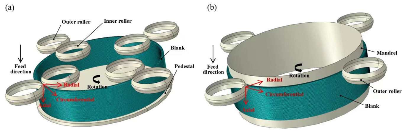
2.1. Establishment of FEA Models for Counter-Roller Spinning and Traditional Mandrel Spinning

In this paper, the elastoplastic models of counter-roller spinning and traditional mandrel spinning were established based on the ABAQUS/Explicit module. The model of counter-roller spinning consists of a pedestal, tubular blank, inner rollers, and outer rollers, as indicated in Figure 1a. The rollers and pedestal were represented by an analytical rigid body, and the tube was considered as a 3D deformable body. The inner diameter, length and thickness of the tubular blank were 400 mm, 100 mm, and 8 mm, respectively. The bottom of the tube and pedestal were fixed, the inner rollers and outer rollers were synchronized and rotated in a planetary fashion around the tube with the rotational speed as 60 rpm. The free rotation of the roller was released so that the roller could be passively rotated when contacting with the tube. The roller feed rate was 1.5 mm/r, and the total thickness reduction was 25%. The geometric parameters of the roller are shown in Figure 2. The geometric parameters of the inner rollers were set as follows: diameter di = 120 mm, front angle αi = 25° and nose radius rρi = 10 mm. The geometric parameters of the outer rollers were set as follows: diameter do = 120 mm, front angle αo = 25° and nose radius rρo = 10 mm.
The FEA model of traditional mandrel spinning was also established with the same process parameters according to counter-roller spinning; meanwhile, the diameter of the mandrel was 400 mm, as shown in Figure 1b. The bottom end of tube and mandrel were fixed, and the outer rollers were rotated in a planetary fashion around the tube.
In addition, the material 6061 aluminum alloy was selected with ρ = 2700 kg/m3, E = 71 GPa, and ν = 0.33, while the constitutive relation was defined by σ = 430.9ε0.14 MPa with the yield stress σs = 346.4 MPa, which was obtained through quasi-static uniaxial tensile testing of the sample at room temperature.
In the FEA model of counter-roller spinning and traditional mandrel spinning, the deformable blank was arranged into 5, 600 and 48 seeds along the radial, circumferential and axial direction, respectively, using the 8-node hexahedral linear reduced integral element (C3D8R), and the total mesh number reached 144,000. The Arbitrary Lagrangian Eulerian (ALE) adaptive meshing technique was adopted to control mesh distortion at each time increment during spinning. The penalty contact method was adopted to simulate the contact between the tube blank/rollers and tube blank/mandrel, and the Coulomb friction law was selected to model the sliding behavior with friction coefficients of 0.05 and 0.2, respectively.

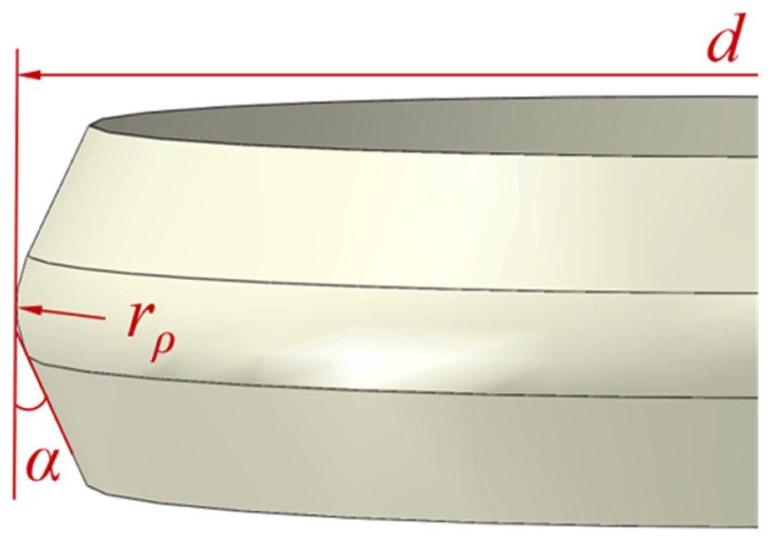
2.2. Design of Numerical Simulation Scheme

The completion of the above FEA models allowed a comparative analysis of the forming characteristics of counter-roller spinning and traditional mandrel spinning, which enabled better exploring the deformation mechanism of the counter-roller spinning and analyzing the influence of the geometry parameters of the inner roller on the tube spinning. Therefore, according to the geometrical parameters of the inner roller in the previous FEA models, the parameter value range was expanded. The geometrical parameters of the inner roller used in the single-factor numerical simulation scheme are shown in Table 1.
In order to explore the significant difference in forming accuracy with the variation of the inner roller geometric parameters, the intermediate value range of the geometric parameters of the inner roller was selected for orthogonal analysis from Table 1. As shown in Table 2, the L9(33) orthogonal numerical simulation scheme was adopted. The variable factors were the diameter, front angle, and nose radius of the inner roller. The outer roundness error, inner roundness error, wall thickness deviation, external spinning force, and internal spinning force were selected as evaluation criteria, and the spinning force was total force due to contact pressure between roller and tube surface.

3. Results and Discussion

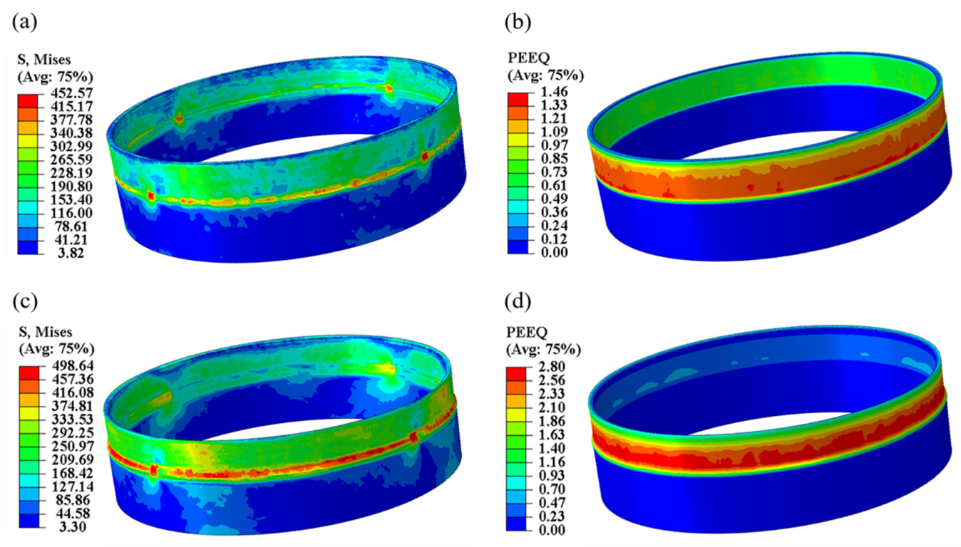
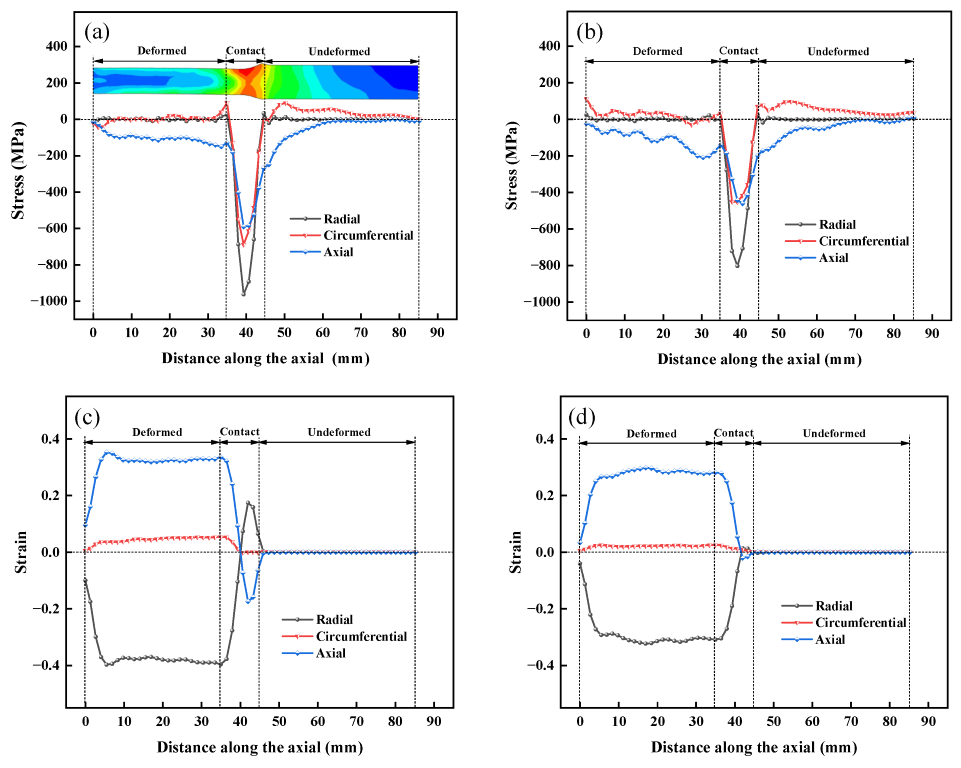
3.1. Stress–Strain Distribution during Counter-Roller Spinning and Traditional Mandrel Spinning

In ABAQUS/Explicit analysis, the mass scaling factor significantly reduces the calculation time of the FEA. The mass scaling factor used for the model was 10,000. The model with the mass scaling factor was verified from the perspective of the energy field to ensure the reliability of the FEA. In general, if the kinetic energy (ALLKE) of the deformed body is less than 10% of the internal energy (ALLIE), it can be determined that the mass scaling factor set in the model is within an appropriate range and the model is valid [34]. The ratio of kinetic energy to internal energy (ALLKE/ALLIE) of the whole calculation process will be output after each numerical simulation to ensure the reliability of each calculation.
Figure 3 shows the stress nephogram on the axial section through the contact zone of counter-roller spinning and traditional mandrel spinning. It can be seen that plastic deformation occurs in the inner and outer layers simultaneously during counter-roller spinning, as the stress is obviously bigger in the contact zone than in other parts, while the stress in the contact zone of traditional mandrel spinning was distinct on the outer layer, which is close to rollers, and the deformation mainly occurred in the outer side of the tube as the inner layer, whose contact with the mandrel was nearly undeformed. Figure 4 shows the stress and strain distribution during the counter-roller spinning and traditional tube spinning with a mandrel. Figure 4a shows the stress of the counter-roller spinning. The maximum equivalent stress was found at the contact zone, and the equivalent stress was distributed in a band shape along the circumferential direction of the contact zone. Figure 4b shows the strain of the counter-roller spinning. The equivalent strain at the outer surface of the blank was greater than the inner surface, and the distribution of equivalent strain values at the inner surface relative to the outer surface was more uniform. Figure 4c,d show the distribution of equivalent stress and strain in traditional mandrel spinning. There was a clearly banded equivalent stress distribution on both sides of the outer contact area of the roller, and there was a relatively small equivalent strain in the deformed area on the inner side of the blank. Compared to counter-roller spinning, the outer roller needs to bear all the thickness reduction during traditional mandrel spinning with the same total thickness reduction while the outer and inner rollers can simultaneously reduce the thickness. Therefore, the equivalent stress and strain outside the blank are more obvious than those of counter-roller spinning.
Figure 5 presents the distribution of stress and strain on the inner and outer sides of the tube through the contact zone along the axial section during counter-roller spinning. As shown in Figure 5a, the contact zones between the outer roller and tubular blank are subjected to significant compressive stress in three directions. The radial stress is maximum, the circumferential stress is greater than the axial stress, and the axial stress is minimum. Figure 5b shows the distribution of stress on the inner side of tube along the axial section. It can be seen that the radial stress is maximum while the circumferential and axial stress are close to each other, and the deformed zone is subjected to circumferential tensile stress, indicating that the diameter tends to expand at the free ending of the as-spun tube. The stress of the inner contact zones is smaller than that of the outer side while the stress fluctuation of the inner deformed zone is larger than that of the outside. Figure 5c,d show the distribution of strain on the outer and inner sides of the tube along the axial section, respectively. It can be seen that the radial strain is the maximum strain, the axial strain is the tensile strain, and the circumferential strain is relatively small. The radial strain on the outer was bigger than that of the inner, indicating that the actual thickness reduction on the outside was bigger than that on the inside while the equal thinning ratio was applied on both sides of tube, wherein the inner and outer rollers also have the same geometric parameters. In the contact zone, the metal pileup that occurred in front of the outer roller was higher than that of the inner side; thus, the outer rollers were subjected to more pressure than inner rollers. As the roller was feeding along the axial direction, the axial force caused compressive strain on the front of the roller.

3.2. Metal Flow during Counter-Roller Spinning and Traditional Mandrel Spinning

Figure 6 shows the material displacement of the counter-roller spinning and traditional mandrel spinning from the perspective of the radial cross-section of the blank when the axial feed to distance was 10, 20, and 30 mm, respectively. During counter-roller spinning (see Figure 6a), when the axial feed distance d of the roller was 10 mm, due to the initial stage of spinning, the material underwent significant deformation, and there was great instability in the metal flow. In counter-roller spinning, the metal in the unformed zone of the tube was prone to flow to the pileup on the outer side. Therefore, the pileup on the outer side of the tube was higher than on the inner side. The metal in the formed zone flowed upwards and tended to shift toward the outside. This result was consistent with the phenomenon of flaring at the free ending of the as-spun tube. In traditional mandrel spinning (see Figure 6b), the metal flowing direction at the free ending of the tube was more prone to mandrel. Compared to counter-roller spinning, the outer roller needs to add a greater thinning on the blank. Therefore, more metal flowed to the pileup below the roller, and a higher metal pileup was generated on the outer side of the blank. As the axial feed distance of the roller increases to 30 mm, spinning has entered a stable period. The metal flow trajectory during counter-roller spinning tended to be symmetrical with the centerline of the tubular blank thickness, which was consistent with the study by Xiao et al. [35]. In the deformed zone of traditional mandrel spinning, the metal flow trajectory tends to be more inclined to the mandrel and tends to be stable. The blank snuggling closely to the mandrel and forming the accuracy of the blank was guaranteed. It can be seen that flaring was more prone to occur in the initial stage of counter-roller spinning compared to traditional mandrel spinning.

3.3. Contact Area during Spinning with Various Geometric Parameters of Inner Roller

Figure 7 shows variation curves of the contact area of the roller with the geometric parameters of the inner roller. Figure 7a shows the evolution of the contact area under the inner roller with various diameters. As the diameter of the inner roller increased, the contact area under the inner roller increased continuously. The inner roller provided better circumferential support for the inner side of the tube, and the contact area of the outer roller was increased. Figure 7b shows the evolution of average contact area of roller with various diameters. The average contact area of the rollers both increased with the increase in diameter. Moreover, the inner average contact area increased more than that of the outer roller. Figure 7c,d show the evolution of the contact area under the inner roller with various front angles. As the front angle of the inner roller increased, the average value of the contact area of the inner and outer roller decreased slightly. However, increasing the nose radius of the inner roller will increase the average contact area of the roller (see Figure 7f). Overall, the diameter of the inner roller has the greatest impact on the contact area, while the influence of the front angle and nose radius was relatively small.

3.4. Spinning Force during Spinning with Various Geometric Parameters of Inner Roller

Figure 8 shows variation curves of the spinning force of the rollers with the geometric parameters of the inner roller. The average value of the spinning force during the steady stage was obtained. As the diameter of the inner roller increased, the contact area under the inner roller increased (see Figure 7b). Therefore, as shown in Figure 8a, the spinning force of the rollers on the tube also increased. Figure 8b shows that the front angle was inversely proportional to the spinning force. As the front angle increased, although the metal surface was more prone to the pileup and increased the feed resistance of the roller during spinning, the overall spinning force gradually decreased due to the decrease in the contact area (see Figure 7d) between the front angle end of the roller and the blank. Figure 8c shows that when the nose radius increased, the internal support of the blank was better and more stable, and the contact area under the inner and outer rollers both increased (see Figure 7f), which in turn caused the spinning force to increase.

3.5. Roundness Error and Wall Thickness Deviation of As-Spun Tube

Figure 9 shows the evolution of the roundness error and wall thickness deviation with the various geometric parameters of the inner roller. The roundness error was calculated by the difference between the maximum and minimum radius on the same section. The wall thickness deviation reflected the relative deviation between the actual value and the ideal value of the wall thickness of the blank, and it was defined as the difference between the maximum and minimum wall thickness on the same section. It was observed that the inner roundness error was close to that of the outer when the diameter of inner rollers was 140 mm or 160 mm (shown in Figure 9a). Increasing the diameter of the inner roller was beneficial for improving the forming precision, as the roundness error and wall thickness deviation decreased with the increase in the inner roller diameter. Figure 9b shows the evolution of roundness error when the front angle increases from 15° to 35°. It can be seen that the error values increased initially and then decreased with the front angle increasing from 15° to 30°. The roundness error increased significantly as the front angle increased from 30° to 35°. An excessive front angle caused significant metal accumulation in front of the roller, causing the metal flow to be unstable. Therefore, the front angle should not be too large, and it was more suitable to choose a front angle within the range of 15–30°. Figure 9c shows the variation of the roundness error and wall thickness deviation with the nose radius. It can be seen that the roundness error and wall thickness deviation gradually decreased when the nose radius increased, indicating that the increase in nose radius promoted the inner roller to have better support for the inner side of the blank, and at the same time, the overlapping part of the motion trajectory of the roller increased and then improved the surface roughness. The roundness error increased sharply when the nose radius was greater than 12 mm; combined with the spinning force curve (see Figure 8c), it indicated that an excessive nose radius would increase the spinning force, which could cause instability of the blank during the counter-roller spinning.

3.6. Significance Level during Spinning with Various Geometric Parameters of Inner Roller

SPSS is one of the commonly used software for statistical analysis of orthogonal experiments [36]. The results of the orthogonal experiment were imported into SPSS 26 software with univariate analysis from the General Linear Model. The fixed factors were the diameter, front angle and nose radius of the roller. The dependent variables were the outer roundness error, inner roundness error, wall thickness deviation, outer spinning force and inner spinning force. The results of the orthogonal experiment are listed in Table 3.
The average value of each factor was calculated, and the influence of the geometric parameters of the inner roller on the dependent variables is shown in Figure 10. The roundness error decreases with the increase in diameter and nose radius of the inner roller, while it increases slightly with the front angle (see Figure 10a). The wall thickness deviation is shown in Figure 10b; it decreases with the increase in roller diameter and nose radius. As the front angle increases, the wall thickness deviation initially decreases and then increases. As shown in Figure 10c, increasing the diameter, front angle and nose radius will increase the spinning force; moreover, the diameter has the most signification influence.
Figure 11 shows the histogram of the significance level during spinning with various geometric parameters of the inner roller. It can be seen that the significance value of the diameter for the spinning force was less than 0.05, indicating that the diameter of the inner roller has a significant impact on the inner and outer spinning force. The order of significance of the geometric parameters of the inner roller on roundness error and wall thickness deviation was as follows: nose radius > diameter > front angle. Obviously, the nose radius of the inner roller had a great influence on roundness error and wall thickness deviation. The order of significance of the geometric parameters of the inner and outer spinning force was as follows: diameter > nose radius > front angle, indicating that the inner roller diameter was mainly affected by the spinning force. The front angle of the inner roller had the least impact during the counter-roller spinning.

4. Conclusions

The deformation characteristics and spinning defects were investigated by FE simulation. The influence of inner roller geometric parameters on counter-roller spinning was analyzed by a single-factor experiment and orthogonal experiment. The following conclusions were obtained:
(1)
During counter-roller forming, when the same geometric parameters were used for the inner and outer rollers, the equivalent stress and strain generated by the outer roller were greater than those of the inner roller. The radial stress was the maximum principal stress, while the axial and circumferential stresses were relatively small. The flaring on the free ending of the tube was more prone to occur in the initial stage of counter-roller spinning compared to traditional mandrel spinning.
(2)
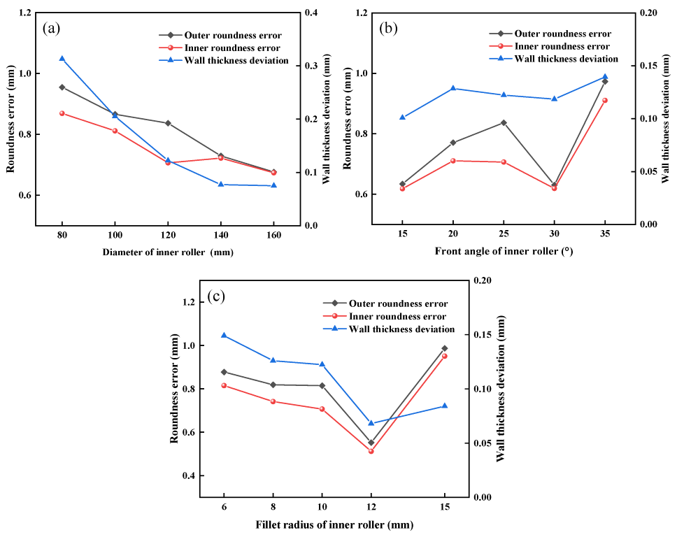
The roundness error and wall thickness deviation decreased with the increase in inner roller diameter and nose radius, indicating that the increase in diameter and nose radius could promote the inner roller to have better support for the inner of the tube blank, while an excessive nose radius would increase the spinning force. It was more suitable to choose a front angle within the range of 15–30°; the roundness error increased significantly as the front angle increased from 30° to 35°, and the excessive front angle caused significant metal accumulation in front of the roller, and the metal flow tended to be unstable.
(3)
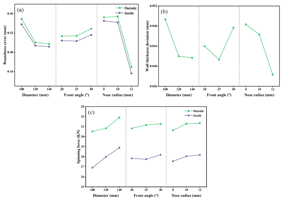
The influence of geometric parameters of the inner roller on forming was analyzed based on orthogonal experiments. The nose radius of the inner roller had a great influence on the roundness error and wall thickness deviation. The diameter of the inner roller mainly affected the inner and outer spinning force. The front angle of the inner roller had the least impact during the counter-roller spinning.

Author Contributions

X.Z.: Methodology, investigation, writing—original draft, writing—review and editing, investigation, visualization, funding acquisition. Z.M.: Methodology, investigation, writing—original draft, data curation. H.Z.: Investigation, data curation. P.W.: Visualization, conceptualization. W.S.: Visualization, supervision, formal analysis. G.Y.: Visualization, conceptualization, formal analysis. All authors have read and agreed to the published version of the manuscript.

Funding

This work was supported by the National Natural Science Foundation of China (No. 51905327) and the Natural Science Foundation of Shaanxi University of Science and Technology (No. 2018BJ-11).

Data Availability Statement

The data that support the findings of this study are available from the corresponding author upon reasonable request.

Conflicts of Interest

The authors declare no conflict of interest.

References

  1. Music, O.; Allwood, J.M.; Kawai, K. A review of the mechanics of metal spinning. J. Mater. Process. Technol. 2010, 210, 3–23. [Google Scholar] [CrossRef]
  2. Xia, Q.; Xiao, G.; Long, H.; Cheng, X.; Sheng, X. A review of process advancement of novel metal spinning. Int. J. Mach. Tools Manuf. 2014, 85, 100–121. [Google Scholar] [CrossRef]
  3. Zhang, L.; Yang, N.; Li, Z.; Tao, J.; Xu, J.; Li, F.; Zhao, S. Progresses and applications of counter-roller spinning technology for metal thin-walled cylinders. China Mech. Eng. 2022, 34, 1–13. [Google Scholar] [CrossRef]
  4. Wong, C.C.; Dean, T.A.; Lin, J. A review of spinning, shear forming and flow forming processes. Int. J. Mach. Tools Manuf. 2003, 43, 1419–1435. [Google Scholar] [CrossRef]
  5. Zhan, M.; Yang, H.; Guo, J.; Wang, X.X. Review on hot spinning for difficult-to-deform lightweight metals. Trans. Nonferrous Met. Soc. China 2015, 25, 1732–1743. [Google Scholar] [CrossRef]
  6. Cao, X.; Zhang, L.; Yang, Y.; Mou, S.Z.; Han, D. Progress of research on counter-roller forming. Hot Work. Technol. 2013, 42, 115–117. [Google Scholar] [CrossRef]
  7. Sun, Y.; Cao, X.; Yang, Y.; Bai, X. Research on study status and development prospects of large-diameter cylinder by counter-roller spinning technology. Aerosp. Manuf. Technol. 2022, 231, 16–22. (In Chinese) [Google Scholar]
  8. Zhang, D.; Zhu, C.; Zhao, S. Progresses of counter-roller spinning equipment and its applications for large-scale tubular components. China Mech. Eng. 2020, 31, 1049–1056. [Google Scholar] [CrossRef]
  9. Xu, Y.; Zhang, S.; Li, P.; Yang, K.; Shan, D.B.; Lu, Y. 3D rigid-plastic FEM numerical simulation on tube spinning. J. Mater. Process. Technol. 1999, 113, 710–713. [Google Scholar] [CrossRef]
  10. Quigley, E.; Monaghan, J. Enhanced finite element models of metal spinning. J. Mater. Process. Technol. 2002, 121, 43–49. [Google Scholar] [CrossRef]
  11. Yang, J.; Ma, S.; Wu, F. Status of appliance and trends of numerical simulation in spinning technique. Mod. Manuf. Technol. 2011, 1, 130–133. [Google Scholar] [CrossRef]
  12. Yoshihara, S.; Mac Donald, B.; Hasegawa, T.; Kawahara, M.; Yamamoto, H. Design improvement of spin forming of magnesium alloy tubes using finite element. J. Mater. Process. Technol. 2004, 153–154, 816–820. [Google Scholar] [CrossRef]
  13. Takahashi, Y.; Kihara, S.; Nagamachi, T.; Higaki, K. Effects of neck length on occurrence of cracking in tube spinning. Procedia Manuf. 2018, 15, 1200–1206. [Google Scholar] [CrossRef]
  14. Jiang, S.; Zhang, Y.; Zhao, Y.; Zhu, X.; Sun, D.; Wang, M. Investigation of interface compatibility during ball spinning of composite tube of copper and aluminum. Int. J. Adv. Manuf. Technol. 2017, 88, 1–8. [Google Scholar] [CrossRef]
  15. Xiao, G.; Zhu, N.; Long, J.; Xia, Q.; Chen, W. Research on precise control of microstructure and mechanical properties of Ni-based superalloy cylindrical parts during hot backward flow spinning. J. Manuf. Processes 2018, 34, 140–147. [Google Scholar] [CrossRef]
  16. Li, Z.; Shu, X. Residual stress analysis of multi-pass cold spinning process. Chin. J. Aeronaut. 2022, 35, 259–271. [Google Scholar] [CrossRef]
  17. Sivam, S.S.S.; Saravanan, K.; Harshavardhana, N.; Kumaran, D. Multi response optimization of setting input variables for getting better cylindrical cups in sheet metal spinning of Al 6061—T6 by Grey relation analysis. Mater. Today Proc. 2020, 45, 1464–1470. [Google Scholar] [CrossRef]
  18. Liu, G.; Li, J.; Yang, Y.; Cao, X.; Sun, Y. Study on the high-strength spinning forming of 7055 aluminum alloy cylindrical parts. Light Alloy Fabr. Technol. 2022, 50, 55–61. [Google Scholar] [CrossRef]
  19. Roy, B.K.; Korkolis, Y.P.; Arai, Y.; Araki, W.; Iijima, T.; Kouyama, J. A study of forming of thin-walled hemispheres by mandrel-free spinning of commercially pure aluminum tubes. J. Manuf. Processes 2021, 64, 306–322. [Google Scholar] [CrossRef]
  20. Jawale, K.; Loukaides, E.G. An investigation of mandrel-free spinning. Procedia Manuf. 2019, 29, 145–152. [Google Scholar] [CrossRef]
  21. Imamura, Y.; Ikawa, K.; Motoyama, K.; Iwasaki, H.; Hirakawa, T.; Utsunomiya, H. Deformation characteristics of Ti-6Al-4V plate in mandrel-free hot spinning. Procedia Manuf. 2018, 15, 1207–1214. [Google Scholar] [CrossRef]
  22. Zhu, E.; Cui, X.; Guo, L.; Ouyang, D. Simulation of power spinning forming process for TB6 titanium alloy cylindrical part. Forg. Stamp. Technol. 2023, 48, 126–134. [Google Scholar] [CrossRef]
  23. Sun, S.; Chen, Q.; Yang, C.; Zhang, Y. Characteristics and development of spinning technology. Alum. Fabr. 2021, 1, 8–11. [Google Scholar] [CrossRef]
  24. Zhu, C.; Zhao, S.; Li, S.; Fan, S. Comparison of mandrel and counter-roller spinning methods for manufacturing large sheaves. Int. J. Adv. Manuf. Technol. 2019, 100, 409–419. [Google Scholar] [CrossRef]
  25. Xiao, G.; Xia, Q.; Cheng, X.; Zhou, Y. Research on the grain refinement method of cylindrical parts by power spinning. Int. J. Adv. Manuf. Technol. 2015, 78, 971–979. [Google Scholar] [CrossRef]
  26. Guo, Y.; Li, M.; Huang, T.; Wang, D.; Zheng, H.; Luo, W.; Li, Y.; Gao, W.; Zhao, X. Research on counter-roller spinning force based on finite element simulation and experiment. In IOP Conference Series: Materials Science and Engineering; IOP Publishing: Bristol, UK, 2019; Volume 563, p. 042069. [Google Scholar] [CrossRef]
  27. Zhang, D.; Li, F.; Li, S.; Zhao, S. Finite element modeling of counter-roller spinning for large-sized aluminum alloy cylindrical parts. Front. Mech. Eng. 2018, 14, 351–357. [Google Scholar] [CrossRef]
  28. Li, F.; Zhu, C.; Shen, Y. Characteristics and rules of counter-roller flow-forming of large tube. J. Netshape Form. Eng. 2022, 14, 11–18. [Google Scholar] [CrossRef]
  29. Xi, Q.; Fan, W.; Lv, W.; Chen, D.B. Orthogonal test of counter roller spinning by numerical simulation. Form. Stamp. Technol. 2016, 41, 154–158. [Google Scholar] [CrossRef]
  30. Sun, Y.; Han, D.; Yang, Y.; Zhao, S. Research on precision of spinning forming of large diameter 30CrMnSiA cylinder. China Met. Equip. Manuf. Technol. 2018, 53, 89–94. [Google Scholar] [CrossRef]
  31. Zhu, C.; Meng, D.; Li, F.; Dong, Y. The Spinning Speed Influence on the Counter-Roller Spinning Process. In Proceedings of the 2022 International Conference on Control, Robotics and Informatics (ICCRI), Danang, Vietnam, 2–4 April 2022; pp. 73–76. [Google Scholar] [CrossRef]
  32. Li, F.; Zhao, S.; Zhu, C.; Zhang, P.; Jiang, H. Influence of process parameters on the forming results of large-sized cylindrical parts during counter-roller spinning. J. Adv. Mech. Des. Syst. Manuf. 2022, 16, 1–13. [Google Scholar] [CrossRef]
  33. Zhu, C.; Li, F.; Dong, Y.; Zhao, S.; Lv, J.; Meng, D. The rollers’ offset position influence on the counter-roller flow-forming process. Metals 2022, 12, 1471. [Google Scholar] [CrossRef]
  34. Han, Z.; Tao, H.; Liu, L. Finite element simulation study on power spinning of sylindrical parts. Mach. Des. Manuf. 2006, 11, 137–139. [Google Scholar] [CrossRef]
  35. Xiao, G.; Xia, Q.; Cheng, X.; Zhou, Y. Metal flow model of cylindrical parts by counter-roller spinning. Procedia Eng. 2014, 81, 2397–2402. [Google Scholar] [CrossRef]
  36. Deng, Z.; Yu, P.; Chen, L. Application of SPSS software in orthogonal experimental design and result analysis. Comput. Study 2009, 5, 15–17. [Google Scholar] [CrossRef]
Figure 1. FEA model of counter-roller spinning and traditional mandrel spinning: (a) counter-roller spinning, (b) traditional mandrel spinning.
Metals 13 01720 g001
Figure 2. Geometric parameters of roller.
Metals 13 01720 g002
Figure 3. Stress nephogram on axial section through contact zone of counter-roller spinning with traditional mandrel spinning.
Metals 13 01720 g003
Figure 4. Stress–strain distribution of counter-roller spinning and traditional mandrel spinning: (a) stress of counter-roller spinning, (b) strain of counter-roller spinning, (c) stress of traditional mandrel spinning, (d) strain of traditional mandrel spinning.
Metals 13 01720 g004
Figure 5. Distribution of stress and strain through the contact zone along the axial of the tube during counter-roller spinning: (a) stress of the outside, (b) stress of the inside, (c) strain of the outside, (d) strain of the inside.
Metals 13 01720 g005
Figure 6. Metal flow in cross-section of blank produced by counter-roller spinning and traditional mandrel spinning: (a) counter-roller spinning, (b) traditional mandrel spinning.
Metals 13 01720 g006
Figure 7. Variation curves of the contact area with the geometric parameters of the inner roller: (a) area with diameter, (b) average area with diameter, (c) area with front angle, (d) average area with front angle, (e) area with nose radius, (f) average area with nose radius.
Metals 13 01720 g007
Figure 8. Variation curves of the spinning force with the geometric parameters of the inner roller: (a) diameter, (b) front angle, (c) nose radius.
Metals 13 01720 g008
Figure 9. Variation curves of the roundness error and wall thickness deviation with the geometric parameters of the inner roller: (a) diameter, (b) front angle, (c) nose radius.
Metals 13 01720 g009
Figure 10. Influence of geometric parameters of the inner roller on dependent variables: (a) roundness error, (b) wall thickness deviation, (c) spinning force.
Metals 13 01720 g010
Figure 11. Significance level of geometric parameters of the inner roller.
Metals 13 01720 g011
Table 1. Geometric parameters of inner roller in single-factor numerical simulation scheme.
ParametersValue
Diameter di/mm80, 100, 120, 140, 160
Front angle αi/(°)15, 20, 25, 30, 35
Nose radius rρi/mm6, 8, 10, 12, 15
Table 2. L9(33) orthogonal numerical simulation scheme.
GroupDiameter di/mmFront Angle αi/(°)Nose Radius rρi/mm
1100208
21002510
31003012
41202010
51202512
6120308
71402012
8140258
91403010
Table 3. The results of the orthogonal experiment.
GroupOuter Roundness Error/mmInner Roundness Error/mmWall Thickness Deviation/mmOuter Spinning Force/KNInner Spinning Force/KN
10.5860.5810.05129.66526.372
20.6090.5950.05030.92126.852
30.4530.4380.04731.01327.513
40.4930.4880.04430.81628.089
50.4350.4270.03131.03027.981
60.5730.5670.05130.67027.856
70.4620.4440.03732.01629.062
80.4990.4880.04331.54528.436
90.5310.5430.04532.15029.199
Disclaimer/Publisher’s Note: The statements, opinions and data contained in all publications are solely those of the individual author(s) and contributor(s) and not of MDPI and/or the editor(s). MDPI and/or the editor(s) disclaim responsibility for any injury to people or property resulting from any ideas, methods, instructions or products referred to in the content.

