1. Introduction
Threaded fasteners, such as bolts and screws, are mechanical connections used to join two or more components. Because of their low cost, high durability, and flexibility in assembly and disassembly, these joints have found widespread use in aerospace and automotive engineering [
1,
2,
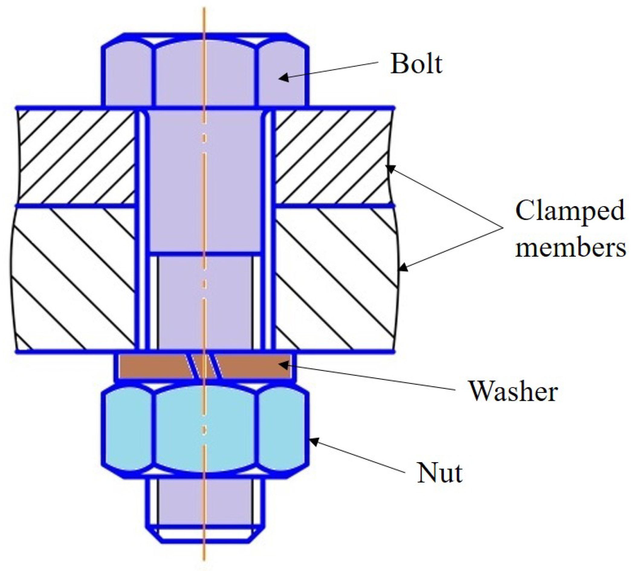
3]. Therefore, these are appropriate for applications that require maintenance or repair. A bolt, nut, and washer are the standard components of a bolted joint (
Figure 1).
Together, they produce a clamping force on the parts being joined. Considering the clamped materials, the loading conditions, and the surrounding environment, bolted joints can be designed and optimized for specific uses. These are less expensive than other mechanical connections, such as adhesives or welds, and are most commonly used to join metal components. However, they can also be utilized for joining wood, plastic, and composite materials.
The primary drawback of bolted joints lies in the fact that the inclusion of screws and nuts adds weight to the entire system, which is generally undesirable in automotive and aerospace applications. As a result, significant research efforts are directed towards exploring alternative joining solutions, such as welding and adhesives. However, these alternative solutions do not allow for easy disassembly, a crucial requirement for the maintenance of many systems. Furthermore, bolts are frequently used in conjunction with other methods to ensure an adequate Safety Factor (SF). Consequently, optimizing bolted joints becomes of paramount importance to ensure that system performance is achieved without introducing excessive additional weight.
The term ‘bolted joint optimization’ refers to the process of selecting the optimal design, material, and tightening procedure to achieve the joint’s intended performance and reliability. During the optimization process, numerous factors are considered, including the loads and stresses to which the joint will be subjected, the material characteristics of the connected components, the environmental conditions, and the desired service life of the joint. Bolt type, diameter, length, thread shape, bolt layout, as well as the quantity of bolts, determine the optimal bolted joint design. The process of optimization may also involve selecting the best order for tightening bolts with the appropriate tightening method and the correct fastener torque or tension level. The ultimate goal of fastened joint optimization is to provide an efficient and robust connection that complies with design specifications and provides a high level of safety and performance. This is usually achieved by defining an appropriate Safety Factor (SF), the value of which typically varies between 1.5 and 3, according to the application of the joined system. In addition, by allowing for smaller bolts and fewer fasteners while still maintaining joint strength, optimized bolted joints can help reduce the total weight and cost (for instance, fuel consumption reduction in the automotive field) of the system.
Optimizing bolted joints is of paramount importance in various real-world applications to ensure safety, reliability, and cost efficiency. Optimization plays a pivotal role in the aerospace and automotive industries when designing and manufacturing structures, engine blocks, chassis, and suspension systems, with the aim of enhancing performance while ensuring safety. There have been instances recorded where improper tightening of fasteners and uneven load distribution have led to fatalities and injuries [
4,
5].
The optimization of bolted connections relies on a model of the mechanical behavior of the joint. These models can be constructed using well-established knowledge in the field of mechanical engineering or advanced and sophisticated tools, such as Artificial Intelligence (AI)-based algorithms. Generally, models of bolted joints are developed through three approaches: analytical models, Finite Element Analysis (FEA), and experimental campaigns.
Analytical models adopt a simplified representation of the real system, in order to calculate the stresses and deformations acting on the bolts and, as a consequence, on the entire structure. These simplifications allow for solutions to be obtained in a short time, but may fail to include relevant aspects of the real system.
Due to its versatility, FEA allows researchers to calculate more complex systems and include multiple physical effects in the model. For this reason, FEA has extensively been used during the optimization of bolted joints. The results obtained through this method are highly influenced by the choice of mesh type and size. Different mesh types affect the accuracy, convergence, and computational efficiency of the analysis. Finer mesh with higher number of elements would provide more accurate results by capturing complex geometry features instead of a coarse mesh. On the other hand, an excessive number of elements may negatively affect the convergence rates, simulation cost and analysis efficiency.
Experimental tests are widely adopted in the study of bolts, as they are the only way to observe all the real phenomena affecting the performance of the joint. In the literature, researchers have used different factors for their studies depending on the response variable and applied loading conditions. The most prominent factors during bolt optimization were bolt layout, preload, bolt class, material of plates, friction coefficients, bolt diameter, bolt length, and bolt quantity. Most of the studies in the literature adopt a full-factorial Design Of Experiment (DOE) approach. Nonetheless, this approach may result in a high number of tests when several factors and levels are considered. Therefore, several researchers adopt Taguchi’s method to reduce the number of tests [
6].
This paper summarizes the different optimization strategies available in the literature. The most prominent factors for optimizing bolted joints (
Figure 2), including bolt layout, bolt stresses/shape, bolt tightening strategies/sequences, diameter, and length, are considered in the paper. The goal is to provide an overview of the literature and highlight future aspects.
3. Optimization of Bolt Layout
The layout of a bolted joint refers to the arrangement and positioning of the bolts and other joint components. It is a crucial part of the joint design since it affects the joint’s performance and reliability. The bolted joints’ layout can influence how loads are distributed across the joint. Optimizing the layout makes it possible to ensure that the loads are distributed evenly, which can help reduce the risk of fatigue failure, cracking, or other forms of damage. Joint strength, stiffness, and durability can all be increased through layout optimization even for a reduced strength of any single bolt. With an appropriate layout, one may reduce the size and number of bolts used to secure a joint, which could minimize weight and cost.
In a study, Khurshid [
8] investigated the displacement and stress distribution due to shear load on a four-bolted model. The study utilized numerical and experimental techniques, where four M16 steel bolts were arranged in different layouts (
Figure 3).
The bolts and the members were made of structural steel with Young’s modulus of 210 GPa. The findings indicated that layout ‘A’ led to lower stresses due to the broader bolts spread from the center. Furthermore, the stresses were not uniformly distributed across all bolts, and the bolt closer to the edge of the applied load experienced higher stress levels. Moreover, he developed a layout factor (
) to find the best-optimized bolt positions. From the analysis of different bolt layouts, it was found that the bolts closer to the loading edge are critical and depend on the distance from the edge and the centroid. This layout factor is only valid for bolts with equal spacing. The bolt layout factor (
) is given in Equation (
1), a higher value of
has more load on the critical fastener and vice versa [
9].
where
;
;
;
n the number of bolts;
E is the edge distance;
is the distance from the centroid to the critical bolt.
The impact of bolt layout on the dynamic stiffness of a hobbing machine column was examined using ANSYS software. The findings revealed that increasing the number of bolts enhanced the natural initial four-order eigenfrequency and improved dynamic stiffness. However, the study demonstrated that adding more bolts could not necessarily result in better outcomes. As the number of bolts increased, the added value of natural frequency decreased, and eventually, the natural frequency became almost constant. Among the three layouts tested, the front-to-back arrangement under the constraint of eight bolts was found to be the most effective. Nevertheless, the difference in the dynamic stiffness value of the natural frequency was less than one percent, suggesting that the influence of bolt arrangement on the column’s dynamic stiffness could be ignored [
10]. In another study [
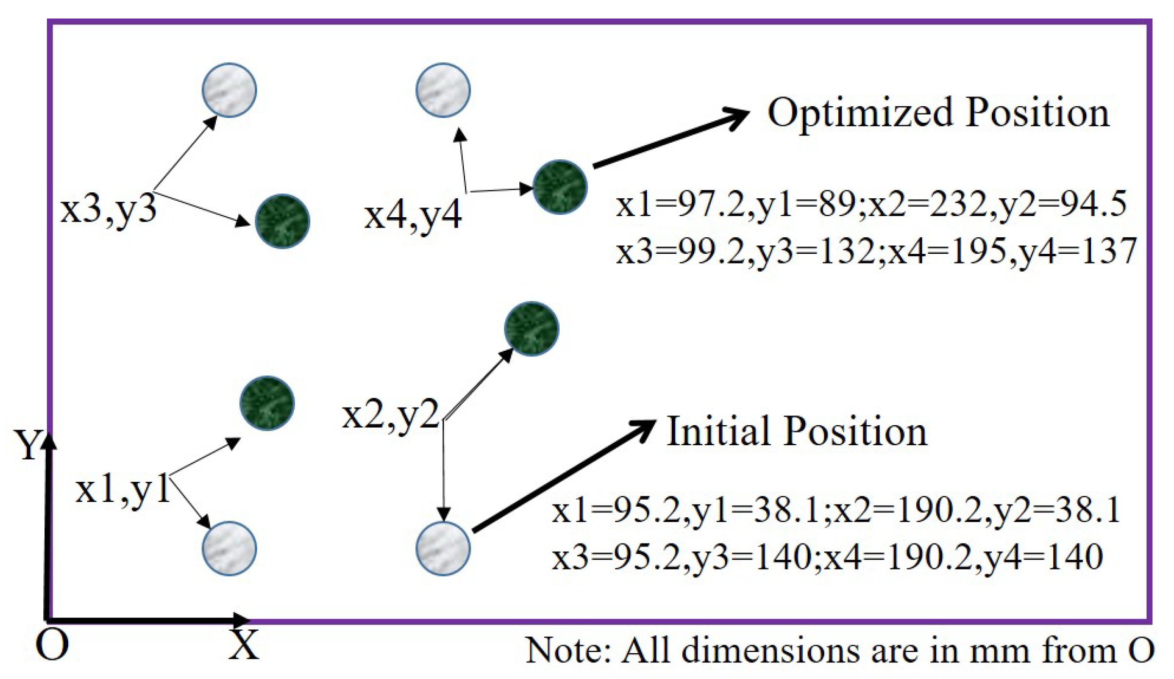
11], a bending load was applied to a pinned joint cantilever member to investigate the distribution of stresses. A Genetic Algorithm (GA) coupled with the ANSYS FEA tool was used to model the problem. The research results concluded that uniform distribution of stresses could be achieved by preventing stress concentrations, and the GA was more efficient. Moreover, the wider the layout of bolts from the center, the greater the strength. Similarly, the genetic algorithm was used to optimize the screws layout to minimize the acceleration/vibrations in an electronic circuit component. MATLAB was used to optimize the bolts’ position, and PATRAN conducted FEA analysis. The results from the optimization showed a 67% reduction in the acceleration from 43.9 m/s
2 to 14.4 m/s
2 (
Figure 4) [
12].
Using a nonlinear 3D FEA model, the effect of the circular bolt pattern on the behaviour of an extended end-plate connection was discussed. It was deduced that the circular pattern improves the connection strength and enhances the energy dissipation capability of the system compared to the rectangular pattern (
Figure 5). This phenomenon is the result of the circular connection’s improved distribution of bolt forces [
13].
Tan et al. [
15] carried out a study with a close topic. The impact of bolts in rows was investigated. Experiments indicate that the actual capacity per bolt decreases when the number of bolts in a row increases. This is called the ‘row effect’ on strength. In another study, the row spacing and bolt spacing effects on 6 and 4 bolts were considered for wood–steel connections. Based on the findings, the average ultimate test load increased by 15% when bolt spacing increased from 4d to 8d for configurations with two rows of two bolts. However, the estimated capacity increased by 75%, and the predicted acceptable design value improved by 47% as the bolt spacing increased [
16]. A single- and double-row fastener configuration were compared for a pressure vessel design without changing other parameters. The double-row fastener is proven to be more robust, and fastener stresses were lowered compared to their strength. The single-row design increased peak fastener loading by 15% and the seal-opening gap by 44%. Moreover, the greater number of bolts was more effective in increasing the damping [
17]. To further explore their impact on the induced prying forces, bolt forces, and force total-deformation responses for extended end-plate connections, a parametric analysis was done on various column flange thicknesses and bolt patterns (circular and rectangular). From the results, the circular bolt pattern is more ductile and exhibits lower secondary prying forces compared to the rectangular one [
14].
The complex potential theory, variational formulation, and genetic algorithm have been used to create an analysis tool to determine the best bolted lap joint designs [
18]. Laminate thickness, layup, bolt location, bolt flexibility, and bolt size were considered design variables, while strength was an objective function. In conclusion, the best and worst variable-size bolt configurations were suggested to withstand the shear load. It was observed that the strength would be higher if bolts were of different sizes and placed apart from the centroid. Similarly, a tool was developed to optimize the bolt locations to equalize the shear load on 3- and 4-bolted models [
19]. The optimization was done using insight software, and validation was performed through FEA analysis. Initially, the stress analysis was performed on given locations, and then locations were changed to obtain an equal load distribution on each bolt. It was observed that the force difference between the first critical and last bolt reduced significantly with the new optimized locations.
A new partheno-chaos genetic algorithm (PCGA) is proposed by combining the partheno-genetic algorithm (PGA) and chaos genetic algorithm (CGA) to optimize the bolt layout to reduce the stresses at the hole edge of aircraft wings [
20]. Compared with the original bolt layout design, the maximum hole edge stress is decreased by 31% under a surface pressure load of 30 MPa. After the optimization, the number of bolts was decreased by 10%, and the maximum equivalent stress of the rib and skin decreased by 23.36% under severe conditions. The Response Surface Methodology (RSM) optimization was applied to find the best hole positions to minimize the stresses in wooden laminated veneer lumber (LVL) composites (
Figure 6). At the initial bolt-hole position, the maximum stress was approximately 23.2 MPa, while the optimized stress value was 20 MPa. Consequently, the maximum stress was reduced by roughly 16% [
21].
In addition, a method based on a linear regression approach to determine a bolt spacing formula for bolted flange joints was presented. It relies on an analytical model derived from the theory of circular beams on a linear elastic frame. Equation (
2) suggests a generic formula based on flange dimensions (Af, Bf), thickness (tf), and gasket-to-flange stiffness ratio (Eg/Ef). A reasonably accurate estimation of the bolt spacing (H) was determined while testing it against five different bolted joint sizes [
22].
Oinonen et al. [
23] found the optimized bolt layout for bracket-to-beam joints subjected to an eccentric shear load. The FEA results revealed that the optimized pattern has evenly distributed loads, and the load at the critical fastener has been reduced to 20% of the initial pattern. The ductility factor of the staggered bolt pattern could be increased from 6.06 to 14.17 without lowering resistance for cruciform stubs under tensile loading, according to a comparison with parallel bolt patterns [
24]. A method for determining the overall yield resistance in tension for top-and-seat angle joints (TSA) of a 1/4-cruciform stub with a staggered bolt pattern for stiffened angle connections has been presented (
Figure 7). The result from the study makes it feasible to specify the angle thickness and bolt type in practical design, and it would be preferable to have an initial stiffness calculation method with stiffeners having a staggered bolt pattern [
25].
In another study, where a cruciform stub with four bolts in a row was proposed, it was concluded that the stub thickness and bolt gauge impact the plastic resistance more than the bolt spacing [
26]. The different layouts, in-line, rectangular, and circular, were studied to minimize the tensile stresses in the T-stub connections. The FEA analysis was performed in ANSYS, and the results were validated experimentally. The findings revealed that the rectangular pattern shows the least tensile stress compared to the other two patterns [
27]. The optimization analysis using artificial neural networks for bolt spacing and arrangements was made using FEA for composite joints. The joint could withstand the most force with the least spacing between bolts. The two horizontal and vertical arrangements were used, and in horizontal alignment, the stress concentration occurred between the two notches [
28].
Certain areas in a structure could require more joints to withstand the loads. A study was conducted to uniformly distribute the load over the different bolted joints without compromising the overall stiffness of the structure. The results of the initial and final layouts were compared, and it was deduced that the optimized design has the minimum load difference between critical bolts and other [
29]. To minimize the number of fasteners in an aircraft assembly, three optimizing algorithms, Local Variations (LV), Mesh Adaptive Direct Search (MADS), and Simulated Annealing (SA), were used. The findings showed that SA could not be used since its random character does not produce reliable results for optimization analysis. MADS and the local variations (LV) technique have demonstrated suitability by enhancing the current fastener pattern for all available gaps [
30]. The screw layout optimization analysis was performed on the titanium metal plate to solve the fatigue fracture problem in the femoral bone. A total of four plans with different layouts (
Figure 8,
Table 1) were presented to minimize stress concentration. Finally, an optimum layout (plan 4) was created to improve the fatigue strength of the clamped system and lower the system’s failure probability [
31].
Further, a combination of genetic algorithm and geometric nonlinear finite element analysis were presented to optimize the lug location and bolt pattern in an eccentrically loaded multi-fastener connection to minimize the Von-Mises stress [
32]. From the findings, when the load is applied at an angle of
/4 from horizontal, the optimal connection arrangement produces a maximum stress value that is noticeably lower than the initial configuration.
In their study, Lu et al. [
33] used the gray wolf algorithm to optimize the arrangement of nickel steel plate connectors with a bolt pattern in a triangular configuration. In this study, a structural model for a multi-bolt connection was developed using the ABAQUS software. The surface stress of the connection was analyzed before and after optimization, aiming to validate the effectiveness of the gray wolf algorithm in optimizing the layout of nickel steel flat bolt connections. The findings indicate that when subjected to a force of 15 kN, the optimized upper side nickel steel plate exhibits a reduction of 73.1 MPa in peripheral stress, representing a 24% optimization rate compared to the original bolt structure layout. Additionally, the bolt stress experiences a decrease of 47.7 MPa, corresponding to a 12.5% optimization rate. Furthermore, it is observed that for loads below 18 kN, both the upper nickel steel plate and bolt group exhibit an optimization effect exceeding 10%. The optimization effect diminishes as the load exceeds 18 kN, and the nickel steel plate surpasses its yield limit when the load exceeds 21 kN.
The most important results from the studies in this section may be summarized as:
Most of the researchers used genetic algorithms for optimisation;
The most widespresad software tools are MATLAB for analytical solutions, and ANSYS for numerical simulations;
The layout with a broader spread of bolts from the centroid for rectangular components has shown better results;
For angle beam connections, the circular bolt patterns were found to be more effective when compared to rectangular designs;
The optimal bolt layout, bolt size, and number of bolts dependend on the applied load.
4. Optimization of Bolt Stresses
Stress concentration in bolted joints refers to the phenomenon where the stress levels in the region around a bolt hole or a threaded portion of a bolt are much higher than in the surrounding areas. This is because a hole is drilled through a plate, or a threaded part is added to a bolt, and the object’s shape changes abruptly. The stress concentration factor is determined by a number of variables, including the diameter of the bolt and the thickness of the plate. The sensitivity to this concentration depends on the type of material being used. Material failures, including cracking or fracture, can occur due to the high stress concentration in bolted joints. Optimization of stress concentration in bolted joints is essential for several reasons. First, reducing stress concentration may improve the life of bolted joints and the durability of a structure or machinery. Second, a more uniform distribution of stresses across the bolted joint can contribute to higher load-sharing capabilities and enhanced overall performance if stress concentrations are kept to a minimum. Lastly, improving stress concentration can lead to designs that are more cost-effective, because not thick flanges or expensive materials would be needed to handle high loads. So, engineers can make structures and tools safer, more reliable, and more cost-effective by optimizing the way stress is concentrated in bolted joints. Bolted connections are often subjected to dynamic loading, which can lead to fatigue failure. There are three common failure modes for bolts: under the head, at the thread runout, or in the thread at the nut face. To improve the fatigue life of bolts, there are three main approaches: improving joint stiffness, improving load distribution along the thread, and minimizing stress concentration in the bolt through shape optimization. The stress concentrations that affect the geometry of bolts are one of the main factors limiting their fatigue life strength. As suggested by Pilkey’s study [
34], one of the primary limitations to fatigue life strength in bolts is the stress concentrations that affect its geometry; specifically, 65% of bolt failures occur at the engagement section between the bolt and nut, 20% at the thread run-out, and 15% in the fillet between the shank and bolt head (
Figure 9).
Most threads have a circular root shape, which is seldom optimal. A study was conducted to optimize stress concentration at the thread root, and the shape was modified into an elliptical shape based on the super ellipse. Optimization results are presented for bolts of sizes M8 to M24. The influence of the nominal size was minimal on the design variables, and a stress level increase ranging between 7% and 9% was noted by Niels L Pedersen [
35]. Further, Niels L Pedersen [
36] used FEA analysis to optimize the shape of bolts and reduce stress concentration by introducing an elliptical profile instead of a circular fillet under the head and at the thread’s root. The study found that this new profile reduced stress by a significant amount.
Zhou et al. [
37] performed a combined shape and stiffness optimization study to ensure uniform contact stress distribution. The study used ANSYS and optimized material stiffness and shape as variables to minimize stress concentrations. A similar study was done to look at the stress distribution in Buttress and ACME threads for different symmetrical models, such as those with grooves added to the bolt and nut, steps added to the nut, grooves on the bolt with or without grooves, smaller diameters, taper added to the nut, and grooves on the bolt. These models were designed in 3D, analyzed, and validated using 2D models created to reduce stress concentration. A total of seven different models were tested in ANSYS under tension and bending loading. Model 4: a step is added to the nut with no grooves on the bolt, or the nut was considered optimal (
Figure 10) for both threads with minimal stress concentration factor Kt of 2.05 [
38].
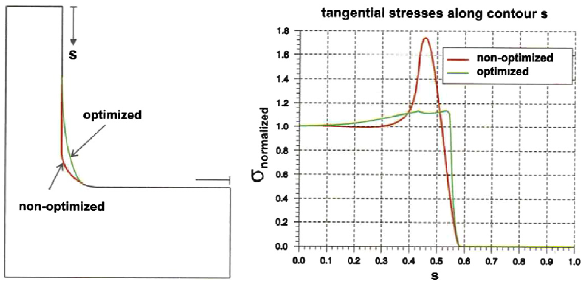
Taylor et al. [
39] proposed a new local curvature method to minimize the stress concentration at the fillet (
Figure 11). They suggested the variable radius curvature at a
radius fillet. The results revealed a decrease in stress concentration by a factor of 2.
Using the finite element method (FEM), progressive quadratic response surface modeling (PQRSM), and the growth-strain method (GSM), the stress concentration in bolt–nut connectors was studied. PQRSM and GSM reduced both the optimized shapes by a maximum of 55%, 59%, and 69%, respectively, compared to the base model, with GSM providing better stress control than PQRSM [
40]. Shape optimization was studied under the bolt head fillet for M12 bolts to minimize the stress concentration by introducing a double circular arc fillet. The genetic algorithm with FEA analysis was used to optimize the stress concentration for fatigue loadings. It was observed that the stress concentration was reduced by 14% compared to the standard circular fillet [
41]. The fillet designs have a higher tensile and bending stiffness with a lower stress concentration factor for both tensile and bending loads, while undercut designs have lower tensile and bending stiffness and higher stress concentration factors [
42].
The method of Maduschka [
43] represents the thread as annular collars with the same properties along the engaged threads. A theoretical model was developed based on Maduschka’s model to study the effect of the washer’s size on the load and stress distribution of screw threads. Later, the theoretical model was validated using FE analysis for M27 screws. The findings demonstrated that increasing the washer’s internal diameter can minimize the peak load and the maximum stress, hence increasing the washer’s strength and fatigue life with minimal effort and expense [
44]. In their study, Yang et al. investigated the effect of proper washer size on the stress distribution of gasketed flanged joints. The optimal washer width could be useful not only to prevent leakage but also to increase the compressive stress and the bolts’ service life [
45]. It was proposed that the new thread runout design would have a substantially longer lifespan than designs proposed by other authors. The shape optimization was performed using ANSYS to improve the fatigue life for M12 × 1.75 mm class 10.9—left-handed threaded cap screws [
46].
The mechanical properties of the bolt threads can be improved through different heat treatment processes. Two sets of fasteners made of 36NiCrMo and 42CrMoV have undergone deep rolling and shot peening to improve fatigue life [
47]. The outcomes demonstrated a favorable effect of deep rolling on fatigue, particularly for the 42CrMoV steel. Contrarily, the outcome of shot-peening was highly dependent on the set of parameters used, and it might either improve or deteriorate the fatigue life in response to the level of induced surface roughness [
48]. A study conducted by Croccolo et al. [
49] examined the impact of shot-peening and lubrication conditions on the performance of 42CrMoV screws subjected to several tightening passes. The findings of the research indicate that the use of lubricant is effective in achieving tightening with small shots and high-impact energy. Conversely, under dry circumstances, using larger shots and lower-impact energy results in significantly low friction coefficients that closely resemble those attainable when lubricants are utilized.
In addition, Fini et al. [
50] studied the fatigue response of bolted joints under various operational conditions. In general, tightening the fasteners at yielding point improved the fatigue response of screws, even though for stress amplitudes higher than 250 MPa, class 8.8 untightened screws were found to have a better fatigue response. The ANOVA analysis and Fisher’s test revealed that there was no statistically significant impact of class 12.9 screws on the fatigue behavior of the yielding method.
Furthermore, a deep rolling process can modify the microstructure at the thread interface, thus enhancing the fatigue life of a bolted joint (
Figure 12). After rolling, the fatigue life of the fasteners increased by approximately 113%, demonstrating the comprehensive effect of these microstructure modifications [
51].
Optimization of a thread root undercut in the roller of the planetary roller screw using FEM was performed. The three root geometries, straight, elliptical, and triangular, were applied at the thread root to minimize the Huber–Mises–Hencky (HMH) stress function. The most optimized geometry was triangular with a 50% reduction in the HMH stress, followed by the straight cut with a 48% HMH reduced stress [
52]. The shape optimization of the pin/lug connection is examined [
53] using a simple elliptical shape instead of the traditional circular one. The results showed an 18% reduction in stress concentration for the elliptical shape pin. Moreover, the stress concentration is highly sensitive to the pin and hole clearance. Gracco et al. [
54] studied the effects of thread shape on the pull-out strength of mini screws for orthodontic applications. The following four thread designs (
Figure 13): buttress,
joint profile, rounded, and trapezoidal were used. The buttress reverse thread shape in the control group consistently exhibited the highest pull-out strength values.
A similar 3D FEA method was presented to evaluate the effect of stress concentration for different thread shapes in bone structures. The study demonstrated that the Von Mises concentration at supporting bone structure was unaffected by using various thread form patterns. However, different thread profiles result in different compressive stress concentrations [
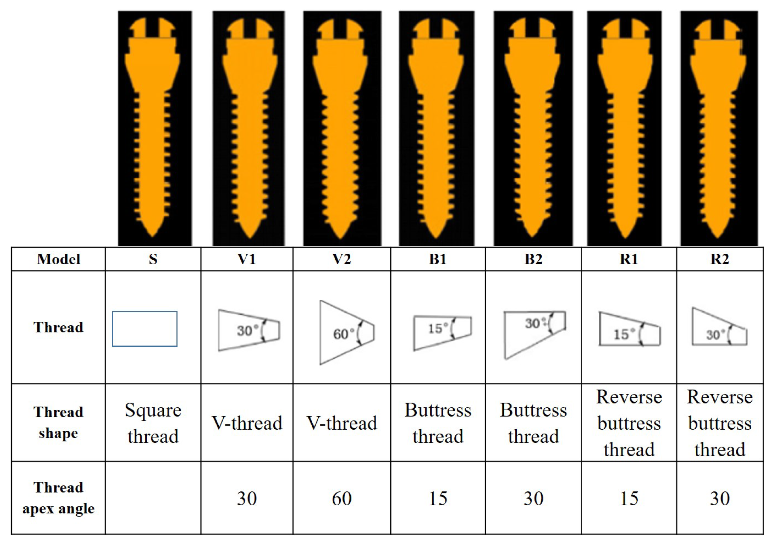
55]. Furthermore, research revealed the effect of mini-screws thread shape on the stress distribution under a torque load. A 6 Nmm torque load was applied while seven thread forms (
Figure 14) (S, V1, V2, B1, B2, R1, and R2) were created. The equivalent stress (EQV) values were in the following order: V1 > V2 > B1 > R1 > R2 > B2 > S. As far as the maximum displacement of the mini screw (Max DM) was concerned, the order was S > B2 > R1 = V1 > B1 > V2 > R1. The Model R2 was the most suitable thread shape that offered a torque force [
56].
Furthermore, a study was performed to check the effect of a slight pitch difference between the nut and bolt. The findings demonstrate that a very large pitch difference may degrade the bolt axial force under a specific tightening torque, and a significant pitch difference may also produce a strong prevailing torque with an anti-loosening effect. The ideal pitch difference that would improve anti-loosening and fatigue life was then suggested [
57]. In preloaded bolted joints with varying thread spacing between the bolt and nut, a new model has been given to evaluate the thread load distribution. A formula is also developed to determine the ideal pitch difference that results in a consistent load distribution, enhancing the joint’s mechanical performance [
58]. Noda et al. [
59] used slightly tapered thread bolts to reduce the stress concentration at the thread’s root. They found that the stress reduced significantly when the thread height was nearer to the bolt head and the nut was closer to the bolt head. Moreover, the results show that the maximum stress is reduced by 20% compared to the standard nut and bolt design. From crack observation in bolt specimens’ cross sections, it was found experimentally that introducing a pitch difference of
α = 15 μm modifies the crack initiation and propagation [
60]. Similarly, for JIS M16 bolt-nut connections, the performance of the fatigue strength improvement was examined analytically and experimentally. Three different root radii with different pitch variations were considered. The fatigue limit of the bolt is increased by more than 30% when the bolt root radius is increased because the stress amplitude and mean stress can be decreased. A good pitch difference also increases the fatigue limit by almost 25%. This is due to the fact that in situations where there is no pitch difference, the crack always starts at No. 1 or No. 2 threads that are close to the bolt head, leading to the bolt’s final failure; however, in situations when there is an appropriate pitch difference, the crack starts at No. 6 or No. 7 threads that are distant from the bolt head [
61].
The most important results from the studies in this section may be summarized as:
In bolt–nut connections, three sections are critical, namely engagement section between bolt and nut, thread run-out, and fillet between shank and bolt head;
Three approaches can improve fatigue life, namely by improving joint stiffness, improving load distribution, and minimizing stress concentration;
Elliptical shapes are more effective than traditional circular shapes in the reduction of stress concentration;
The stresses can also be reduced by enlarging the internal diameter of the washer;
Some studies revealed that the significant pitch difference between nut and bolt might improve the fatigue life and anti-loosening properties of a joint;
Surface treatment processes like deep rolling and shot peening help to minimize stress concentrations and improve the fatigue life.
5. Optimization of Tightening Methods
Bolt tightening refers to applying a specific amount of torque to a bolt or screw to secure it in place and obtain uniform clamping. VDI 2230 and ASME guidelines explain the following tightening methods: torque control, angle control, yield control, momentum control, and hydraulic tensioning [
62,
63]. Despite standard tightening methods, in many cases it is still not possible to obtain the desired pre-load at the end of tightening; therefore, optimization of tightening strategies is necessary for safety, performance, cost-effectiveness, compliance, and efficiency reasons.
Abid et al. [
64] developed an optimized algorithm for gasketed flanged joints to obtain the desired preload based on TCM (torque control method) and SCM (stretch control method). It was observed that the stress values using the optimized algorithm were near the required one with an error of 0–5 MPa compared to manual hit and trial values of 0–50 MPa. Another FEA analysis showed that the SCM is better than the TCM when it comes to the uniform distribution of gasket stress, the highest stress at the hub flange fillet, and the variation in axial bolt stress [
65,
66]. Jung et al. [
67] used a hydraulic torque wrench and pneumatic torque multiplier to tighten the flange bolts with two bolting patterns, legacy pattern and alternative pattern # 3, and ASTM F2482 load-indicating studs were used to measure the loads on their bolts. The study showed that the alternative # 3 bolt pattern with a pneumatic torque multiplier could reduce the assembly time by 54% compared to the legacy pattern. Moreover, the pneumatic torque multiplier has been shown to produce desired bolt load and should be considered a reliable option for faster, controlled torquing.
Benet et al. [
68] analysed the effect of extension tools used for tightening bolts and outlined the best practices for their usage.
Zhou et al. proposed a novel automated method for faastening threaded joints based on visual and force data [
69]. A new tightening machine was made to tighten the bolts for the automobile differential mechanism based on the PLC as a core controller and two screwed shafts by the Profibus-DP communication (
Figure 15). This machine can not only improve the efficiency of automotive assembly but could also improve the pass rate of the differential mechanism [
70].
Several tightening techniques, including JIS B 2251, ASME PCC-1 legacy, ASME alternative #1, #2, and #3, and the three rounds method, were used in an ASME 24" bolted gasketed pipe flanged connection to study the scatter in the axial bolt forces. The leak rate of connections tightened by the JIS B 2251 method was the lowest compared to others; thus, the JIS procedure is the most efficient among others [
71]. Croccolo et al. [
72] investigated the effect of different conditions of lubricant (dry, added oil, Teflon, and ceramic paste) for joints made up of a hexagon socket head screw made of titanium alloy (Ti–6Al–4V), a bush made of aluminum alloy (EN AW 7075 T6) and a steel nut (ISO 4032). Different tightening strategies with 20 retightening have been analyzed using the DOE method and ANOVA. From the study, the ceramic paste showed the best results (
Table 2) in terms of friction coefficients throughout the retightening operations.
A new tightening procedure has been proposed based on the ultrasonic method for the M10 × 60 agrati zinc flake-coated bolt used to fix calipers in a car’s brake system. Firstly, the procedure was applied to the dummy joints, and later tests were performed on the real clippers to enhance the reliability of the previous measurements. The new tightening techniques were evaluated based on the test findings in three areas: embedding resistance, accuracy, and joint security. In this manner, the ideal tightening technique was suggested [
73].
By optimizing the makeup torques using physical test data as input and uniformly distributed preloads as the target function, a significantly more uniform distribution of bolt preloads is achieved. Based on experiments conducted on two different sizes of API flanges, 3-API-15K and 5-API-10K, the variation in the final preload distribution has been reduced to approximately 30% by utilizing the optimized makeup torque distributions [
74]. Adding a preload significantly improves the fatigue life of a dental implant assembly and can generate a more accurate stress distribution on the screw [
75]. An adaptive-gain second-order sliding mode controller (SMC) design was suggested to gain the required pre-load. The results were dramatically improved by applying an adaptive-again algorithm because the second-order SMC’s sliding-surface parameters were the same as the specified control method [
76]. It is further suggested to use an algorithm for a multi-bolt tightening technique that considers elastic interaction and gasket creep relaxation. In the experiment, two cases were considered: without a gasket and with a silicon gasket. When the torque control method is employed, the clamping forces of flange bolts disperse extensively with constant tightening torque [
77].
The three tightening schemes, angle tightening method, torque twice tightening method, and torque-angle twice tightening method, were compared experimentally. Comparing the degree of attenuation of the axis force after 24 hours to the axis force’s dispersion rate reveals that the torque-angle twice tightening procedure is the optimal solution [
78].
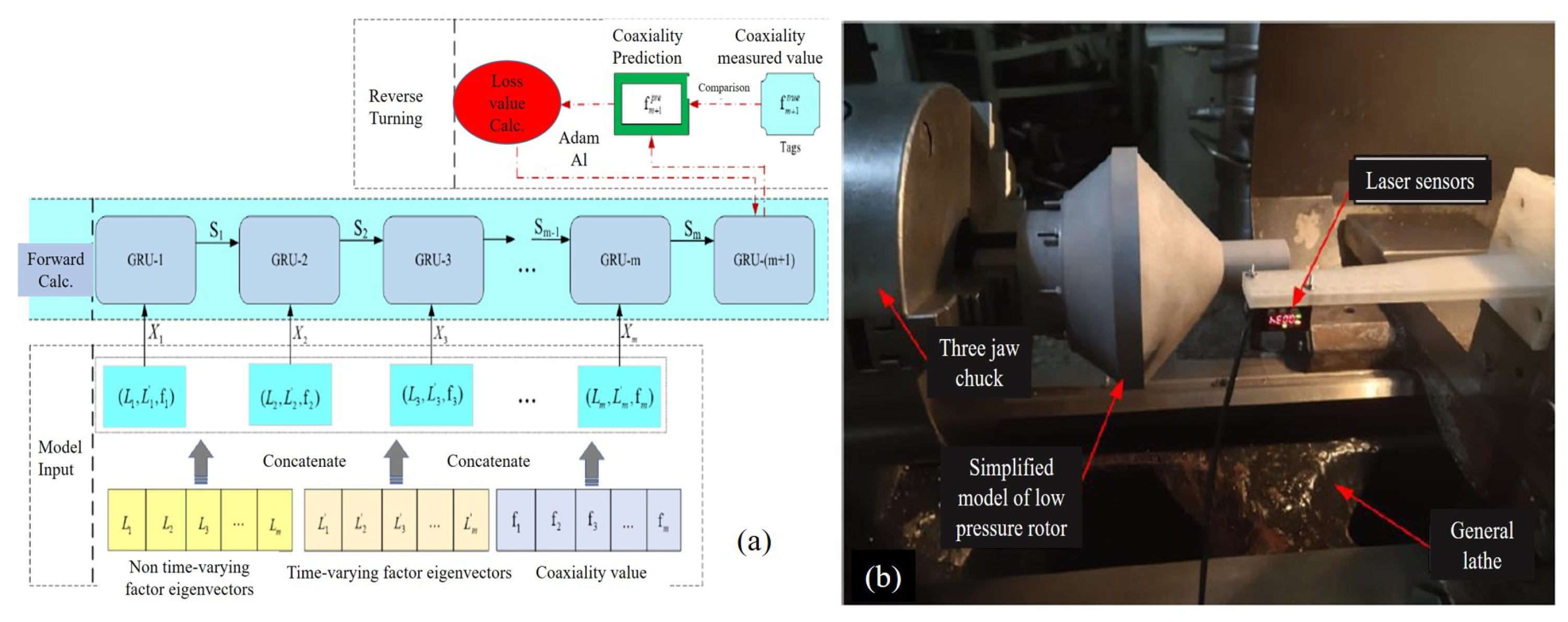
To predict co-axiality (
Figure 16) in the bolt-tightening process for the aero-engine rotor, a semi-physical simulation optimization method based on GRU (gated recurrent unit) network was developed (
Figure 17).
Initially, the elastic interaction matrix was established using simulation data from finite elements. Finally, the bolt preload force was examined as an optimization variable, co-axiality and stiffness as an optimization target, and the tightening torque and preload force of the placed bolts as assembly-process constraints [
79]. Research on the bolted flange tightening technique for contact stiffness of joint surface was done by Zuo et al. [
80]. To improve the tightening method, a correlation model between the initial bolt pre-tightening force and the contact stiffness of the bolted flange is applied. Following optimization, the minimum contact stiffness increased by 6%, while the joint surface’s average and minimum contact stiffness increased by 5%.
It is well known that, when compared to the torque method, bolt tensioners offer more accuracy and uniformity in the final tightening load. Therefore, research on the hydraulic tensioner has been carried out to demonstrate how the tightening load may be calculated from the tension load that has been applied and to suggest a strategy for improving and securing the tightening process [
81]. In order to build a consistent interdependency with the initial clamp load, which is crucial in the process of bolt tightening, a study was conducted on the technique for controlling and analyzing the tightened fastener’s joint distortion and strain fields [
82]. In high-pressure bolted flange vessels, bolts of sizes M70 to M150 are used to prevent failure. In the range of 300 Ton-force (3 MN), a significant amount of force will be applied to each bolt. A so high load cannot be applied by hand-operated wrenches. Therefore, a Hydraulic Bolt Tensioner (HBT) (
Figure 18) was designed and analyzed both analytically and numerically to tighten the bolts with minimum stress-induced.
After several iterations, the stress level was reduced from 3760 MPa in the first iteration to 159 MPa in the fourth iteration [
83]. The effective tensile coefficient, the ratio of the needed clamping force to the initial tension supplied by a hydraulic tensioner, is the most crucial component in the operation of HBT. In one study, using the finite element method, an axisymmetric elastic contact was used to evaluate the tightening process. The coefficient values were assessed for various surface contact design cues [
84]. A simple but comprehensive technique was used to calculate the effective tensile coefficient by applying a useful equation to determine the coefficient’s magnitude. Additionally, the relationship between effective tensile coefficient and grasp length was investigated, taking the effects of the latched plate’s Young’s modulus into account, and the results were compared using experiments and the FEM technique [
85].
A novel tightening tool was invented that directly and accurately controls the bolt’s preload. The tightening tool is made up of a smart wrench and a system for processing signals. The wrench features a PZT sensor that is intelligently integrated into the socket and an electric tripping structure that makes sure the desired preload can be managed effectively. The average preload error was approximately 2%, validating the accuracy and effectiveness of the new tightening tool [
86]. In addition, a few techniques employing variations in electrical resistance properties have been implemented for monitoring fastener tightness [
87].
Foissac et al. [
88] developed a smart tightening method for aeronautical bolted assemblies based on the neural networks. The study compares the performance of smart tightening based on a neural network with epistemic or arbitrary dispersions and conventional tightening. This strategy makes it possible to obtain an accurate estimation of the preload by taking epistemic dispersions into account during the training of the neural network.
The most important results from the studies in this section may be summarized as:
VDI 2230 and ASME guidelines suggested following five tightening methods; torque control, angle control, yield control, momentum control, and hydraulic tensioning;
Few researchers have reported that the torque-angle method is the optimal solution;
The bolt tensioner provides better accuracy and homogeneity in the final tightening load than the torque method;
To minimize the load scatter, multiple tightening passes are recommended;
In high-pressure bolted flange vessels, a Hydraulic Bolt Tensioner (HBT) is used instead of a hand tightening tool.
6. Optimization of Tightening Sequences
Tightening a bolt ensures the joint remains stable and does not loosen over time due to vibration or other external forces. When a bolt is tightened, it stretches and creates a clamping force on its securing components (
Figure 19). The torque or tension required to tighten a bolt depends on factors such as the size and grade of the bolt, the materials being joined, and the desired clamping force. For example, Xuande et al. investigated the particular phenomena determining the effective preload in the case of bolted composite parts [
89].
Over-tightening or under-tightening a bolt can both result in issues such as joint failure, fatigue, or thread damage, so it is important to follow appropriate tightening procedures and use the correct tools and techniques for the specific application.
Optimizing the bolt tightening sequence is important to ensure the joint is appropriately clamped and minimize the effects of elastic interaction [
90]. When multiple bolts are used to fasten a joint, the order in which they are tightened can affect the distribution of the clamping force and the overall stiffness of the joint. As a result, improper tightening sequence can lead to stress concentrations and bolt failure or joint failure. In addition, it is worth noting that tightening all bolts simultaneously is a strategy to prevent criss-cross or elastic interaction phenomena. However, this approach is feasible only when dealing with a limited number of bolts and relatively straightforward geometries. Furthermore, the use of specialized tools is necessary to execute simultaneous tightenings. When confronted with the challenge of tightening a large number of bolts with irregular geometries, simultaneous tightening becomes impractical. Consequently, there is a necessity to resort to a sequential tightening approach in such cases.
Bolt relaxation, is another phenomena that leads to the gradual loss of tension or preload in a bolted joint over time when it is subjected to a constant load or when temperature changes occur. This phenomenon occurs due to the material properties of the bolt and the interaction between the bolt, the nut, and the clamped components. Bolt relaxation can lead to a reduction in the clamping force applied to the joint, potentially compromising the integrity and performance of the assembly. The negative effects of bolt relaxation could be avoided by inspecting the bolt pre-load after a specific intervals of time [
91].
Two well-known optimization techniques are the elastic interaction coefficient method (EICM) and the inverse sequence method (ISM). The EICM method assumes a linear relationship between the load variations of the tightened bolts and the final preload. The elastic interaction coefficient matrix depicts the relationship, which differs for various tightening patterns. Usually, this matrix is obtained by experimental measurements or finite element (FE) modeling. The EICM method is valid only for linear systems. When the bolted joint has a nonlinear behavior, such that produced with a nonlinear gasket material, the matrix of elastic interaction coefficients depends on the extent of gasket compression; thus, this method cannot be used in this particular case. The ISM method analyzes the sequence of bolt loosening from the final stage of bolt loading to its initial state. Starting from the final state, where each bolt has attained a specified preload, the bolts are individually and sequentially loosened to their original state. In other words, the algorithm begins with the final, uniform state of bolt loading and proceeds by loosening each bolt in the reverse order of the tightening sequence. The ISM method applies to linear and nonlinear systems and can be numerically simulated.
During bolt tightening, the attained final load in the bolts is frequently different from the target value due to several factors, including the friction scatter caused by the torque–preload relationship, the embedding of the mating surfaces, and the rotational flexibility of the flanges [
92]. It is well-established that elastic interaction and cross-talk (
Figure 20) are the most significant contributors to scattering [
93,
94,
95,
96].
ASME PCC-1 suggests a number of tightening sequences to minimize the dispersion caused by elastic interaction. A new alternative to the legacy tightening sequence/pattern PCC-1 was also proposed to increase the efficiency and reduce the tightening time and pass [
97]. Similarly, a method for optimizing a tightening sequence for wind generator flange joints is proposed based on a metamodel concept incorporating the EICM and ISM methods. The ISM technique is used for the first pass of an optimized two-pass sequence, while the EICM method is used for the second pass. During the second pass, the system is thought to be linear. The metamodel is designed for flanges with metal-to-metal contact. A total of 20 bolts were analyzed in MATLAB software, and finite element analysis validated the model. It was found that the load distributed uniformly on all bolts, and loosening could be prevented [
98,
99].
The star tightening sequence pattern (
Figure 21) has been used for pipe flanges, ASME B16.5 and ASME B16.47 flanges (NPS 26 inches and above), heat exchangers, and other applications. ASME PCC-1 is another tightening sequence guideline that covers many tightening patterns, including the modified star bolting pattern as an alternative assembly pattern #1 [
100]. A new Tetraparametric Assembly Method (TAM) was introduced to avoid checking preload after every tightening pass using the concept of elastic interaction method [
101]. The model was built in FEA, and the experimental test bench did validation. 20 bolts were used in the test and tightened by the star pattern, with the help of a hydraulic torque wrench. This methodology can measure the final load without measuring after each tightening, thus minimizing cost and time. Furthermore, Nassar et al. [
102] developed a non-linear FEA model to obtain the target preload using sequential and star tightening patterns with single and multi passes tightening. It was concluded that when the tightening passes increased, the loading scatter diminished and approached 97% of the desired with three passes. Further, a few bolts were overtightened by 38% due to the system’s nonlinearity, but it did not cross the yielding.
Based on Markov theory, most commonly, the elastic interaction coefficient, reverse sequence, four-parameter, and elastic interaction stiffness/flexibility methods are used to optimize the preload distribution of bolt flange connections. After optimization, the stress distribution on the bearing surface is comparatively uniform, with a 35.2 MPa reduction in the maximum concentrated stress and a 19.18% reduction in the dispersion degree of stress distribution [
103]. The contact stiffness of bolted assembly structure varies with the bolt-tightening sequences, reported by Wang [
104].
A quality factor (Q) has been created to obtain the required torque according to standard EN1591-1 using a hydraulic torque wrench and three tightening sequences based on the HPIS Z 103 TR, the alternative pattern #1 of ASME PCC-1:2010, and the Legacy cross-pattern of ASME PCC-1:2010. It has been noted that the quality factor (Q), when applied to the initial rounds of the two different tightening techniques, grows more quickly with the round number and practically stabilizes after the application of round 4 [
105].
A new SH-Method tightening sequence was introduced for metal to metal contact (MMC) to clamp bolted flange joints [
106]. According to the ANSYS calculation results, the SH-Method requires fewer tightening rounds, tightening operations, and moving numbers to achieve the target bolt force, and bolt load dispersion is lower for an MMC flange joint when compared to the star pattern and alternative pattern in ASME PCC-1 (
Figure 22). Further, a novel methodology for bolt tightening optimization was proposed based on a digital twin system to improve the efficiency of aerospace engines. In this study, for the first time, two robots were used to tighten the aerospace engine instead of traditional manual tightening. This method makes it uniform, improves bolt residual pre-tightening force after assembly, and reduces the aerospace engine’s stress and deformation [
107]. Similarly, Grzejda et al. [
108] investigated the effect of different tightening sequences on the preload distribution for linear and nonlinear multi-bolted connections. It can be concluded that as a result of tightening subsequent bolts, the preload in bolt No. 1 decreased by less than 8% after the second cycle and by less than 5% after the third tightening cycle in the case of the SB-NL system model, and by less than 9% after the second cycle and by less than 6% after the third tightening cycle in the case of the SB-L system model.
According to Ji et al. [
109], the diagonal tighten was better than the serial tighten for the non-uniform degree of deformation of the valve in the fluid bag, and when compared to the interval load, the optimal solution of the uniformity of deformation of the valve for load at the same time was good. Moreover, a study was conducted to determine the loading scatter due to the tightening sequence in the gasket-flanged bolted joints. The results revealed that the loading scatter decreased with the increase in the number of tightening passes, and it can also be reduced by changing the tightening sequence from diagonal to opposite one. Moreover, the scatter was higher when a harder gasket was used [
110].
The effect of three different tightening sequences on the preload (Fp) of M72 bolts of offshore wind turbine has been studied with one additional tightening pass [
111]. The study showed that the tightening order does not affect the final (Fp) value of the first bolt, which can be tightened in any order. All bolts reached the needed (Fp) value after a second tightening pass in the same order. Abid et al. [
112] studied the combined effect of the tightening procedure, tightening sequence, and a number of tightening passes to obtain the desired final preload using 3D FEA analysis. Since bolts are tightened individually, considering elastic interactions, the bolt preload scatter was at its highest when employing the torque control method. The process of tightening the bolt significantly impacts how the bolt behaves when bent. Each bolt exhibits different bending behavior while applying the torque control method. In the stretch control method, bolts that are stretched together exhibit the same bending behavior.
Using an FBG-enabled smart bolt, comparative research of European, C Chinese, and American codes on bolt tightening sequence (
Figure 23) was performed. The pre-load distribution of different tightening sequences was studied experimentally using two rectangular steel plates with sixteen 8.8-grade bolts. The study revealed no significant difference between the three tightening sequences, and using Chinese code can achieve more uniform distribution and less load scatter [
113].
A very interesting study was conducted at the University of Texas, where a tightening tool equipped with a camera was used to detect the bolt location and to identify the most suitable tightening sequence based on artificial intelligence (AI). The developed program is comparatively easy to set up, and the operator does not need to test different algorithms for tightening sequences and locations and can identify all the test cases correctly, thus achieving an accuracy of 100% [
114].
Xioreng et al. [
115] studied the effect of the screw-tightening sequence of dynamic compression plate (DCP) used in orthopedics based on stress distribution. In the idealized finite element analysis models of the femoral diaphysis with DCPs, two screw-tightening sequences for the six-hole plate and six sequences for the eight-hole plate were tested. The results in terms of Von Mises stress revealed the same stress distribution at the end for all the tightening sequences; therefore, there is no need to worry the surgeon about the tightening sequence.
Zhu et al. [
116,
117] developed an analytical model to predict and optimize the bolt load on an NPS 4 class 900 weld neck bolted flange joint. The suggested model is based on the theory of circular beams on linear elastic foundations. It can be used to optimize the initial bolt tightening to obtain a uniform final preload with minimum tightening passes in criss-cross and sequential patterns. The maximum scatter for the criss-cross pattern is approximately 18.5%, whereas it is about 11% for the sequential pattern. Additionally, Zhu et al. [
118] proposed a novel tightening sequence methodology based on the analytical model mentioned previously. Two ways were presented to achieve a uniform load with as few tightening passes as possible. A second tightening pass is needed if the load applied to a bolt during the first tightening pass is more than its yield. This means that an ideal two tightening passes are taken into account. The results show that the highest overshoot is usually less with two tightening passes than with a single tightening pass.
Yuan et al. [
119] introduced an innovative method for detecting bolt looseness, employing deep learning techniques and acoustic recognition. The researchers utilized a conventional neural network, specifically a Convolutional Neural Network (CNN), to extract pertinent information from images. Furthermore, they conducted a numerical investigation to assess how the initial prestress levels affect the vibrational frequency of bolted joints. The results of this study highlight the remarkable precision of the proposed methodology in identifying cases of bolt looseness. In addition, the research team developed an iOS application for practical, real-world applications involving acoustic vibration analysis.
The most important results from the studies in this section may be summarized as:
The elastic interaction coefficient method (EICM) and inverse square method (ISM) are the two most well-known optimization techniques;
Elastic interaction and cross-talk are the most significant contributors to load scattering;
The effect of cross-talk can be minimized by applying multiple tightening passes;
The most widely used bolt tightening sequencing patterns are given by ASME PCC-1:2010 standard for flanges joints;
The Chinese codes give a more uniform distribution of loads in comparison to American and European codes.
7. Optimization of Bolt Size
The proper size of the fastener ensures that the joint can withstand the required load and that the connection will remain secure and safe over time. If the fastener size is insufficient, it may fail under a large load or shear force, causing a safety risk. If the size of the fastener is excessively large, overly high weight and expense may arise from the chosen design. To achieve an equilibrium between reliability and efficiency, it is essential to optimize the size of the fastener. In addition, the optimal fastener size depends on the material of the joint, the operating conditions, and the surrounding environment. All of these factors must be considered when choosing the appropriate bolt size for a particular application.
Christian et al. [
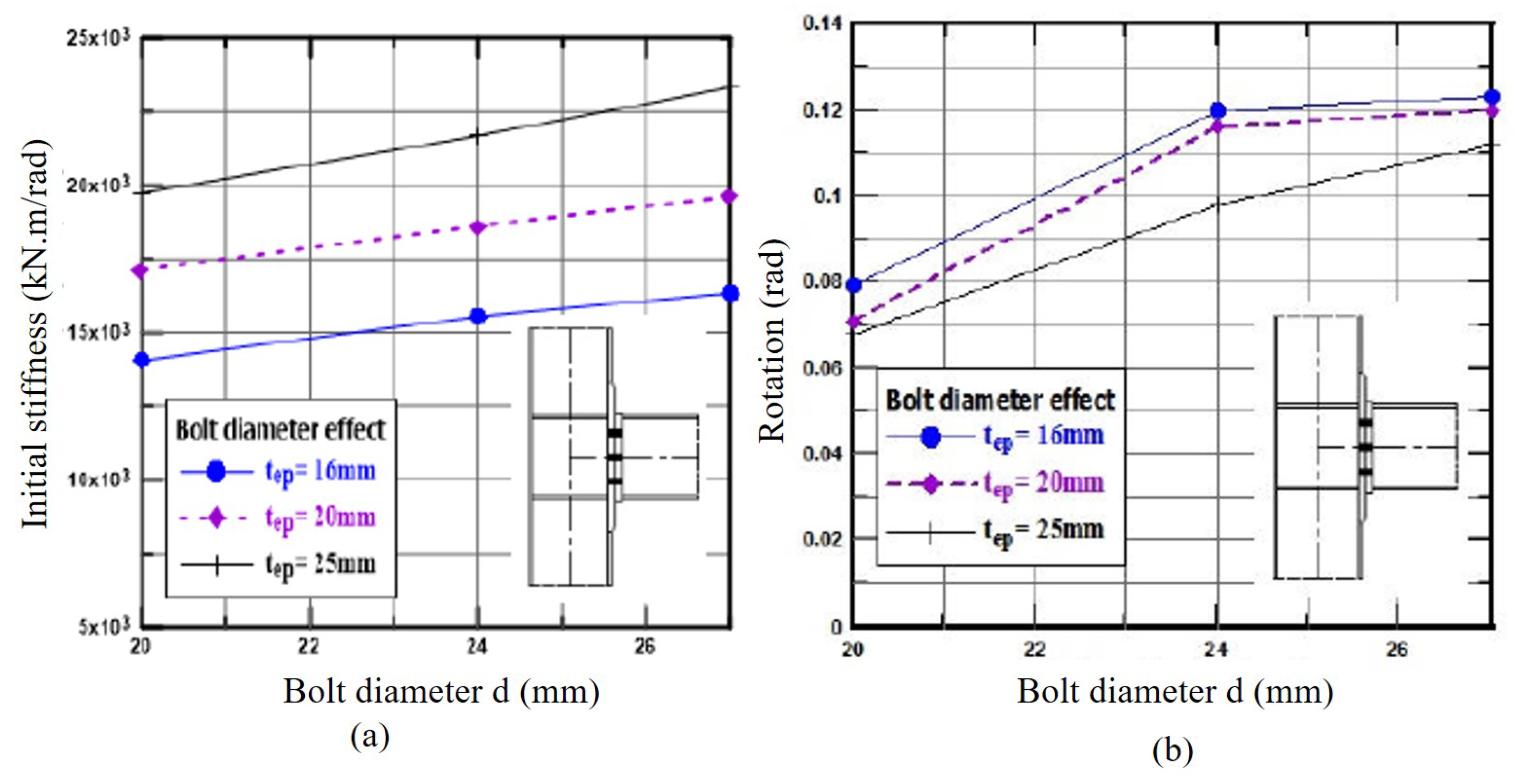
120] studied the effect of bolt diameter and plate thickness to minimize the weight and cost and maximize the safety factor for steel and composite plates. The optimization was conducted in MATLAB using a genetic algorithm to investigate the different factors. A total of 14 bolts of different sizes and layouts were used for higher safety, lower cost, and price. Finally, they found an optimized number of bolts, layout, and diameter to obtain the desired results. Furthermore, the effect of bolt diameter and plate thickness was examined for endplate steel connections. It has been observed that increasing the bolts’ diameter and the end plate’s thickness increases both the initial stiffness and the ultimate moment. By increasing the diameter of the fastener from 20 to 24 mm (
Figure 24), the maximum torque and rotational capacity increase by approximately 14% and 63%, respectively, [
121].
Moreover, the finite element analysis of 20- and 30-mm bolt diameters was performed on the steel plates of thickness 4.7 and 8 mm to check the initial and final stiffness of the plates. The study, which included shank and thread bolted connections, highlighted that the threads reduces the initial stiffness due to the bolt threads cutting into the connected plat but increases the final stiffness [
122]. The bolt grade and both sizes also affect the members’ initial stiffness [
123].
Through the use of ANSYS software, a procedure for selecting optimal configurations of both bolt size and number has been implemented. When optimizing bolted joints, the essential parameters to consider are the bolt size and the number of bolts. Considering that bolts are available in discrete sizes (e.g., M4, M5, M6, etc., for metric bolts), there is only one optimal combination of bolt size and bolt number that will maximize the joint’s efficiency under a given force [
124]. Others have investigated the effect of bolt size on the assembly nut factor for bolt diameter from 1/4 inch to 2 inches. The two anti-seize products (Molybdenum and Nickel) and bolt materials (ASTM A193-B7 and ASTM A193-B8M) were used. The results produced helpful information while choosing the bolt size [
125].
Schnupp et al. [
126] studied the effect of the bolt head with the minimum diameter specified by the standard ASTM F1852 on A325 and A490 strength bolts. The 534 bolts were tested with minimum and manufacturer’s diameter, and the results show that both diameters can bear the same pretension. Moreover, the washers can be removed if the bolt head diameter is equal to the size of the washer. Furthermore, the effect of the bearing surface diameter of M16 bolts on steel plates was investigated to ensure the uniform distribution of pressure. The bearing surfaces of 24, 27, 30, 32, 34, and 36 mm in diameter were used (
Figure 25), and the results calculated by ultrasonic technique revealed that the load distribution was more uniform for higher diameters due to the larger bearing surface [
127].
The bolt stiffness increases significantly with the increase in diameter and has a minor change with the increase or decrease in external loads. Furthermore, the member’s stiffness rises as the bolt’s diameter rises; this rise in member stiffness owing to the rise in bolt diameter can be attributed to the rise in the washer face area. For the 24-mm bolt, the stiffness decreased by 4.4, 4, and 3.7 percent when steel members were replaced with aluminum members for the 12/20, 16/20, and 20/20-mm member thickness combinations, respectively. In contrast, the stiffness decreased by 7.5, 7.4, and 7.1 percent when steel was replaced with cast iron for the same bolt and member combination. Changing from steel to cast iron over aluminum members caused a 7.8, 7.6, and 7.4-percent decrease in bolt stiffness [
128]. According to the findings of others, the initial stiffness of the end-plated connection improves along with an increase in either the bolt diameter or the end-thickness [
129].
Further, Griza et al. [
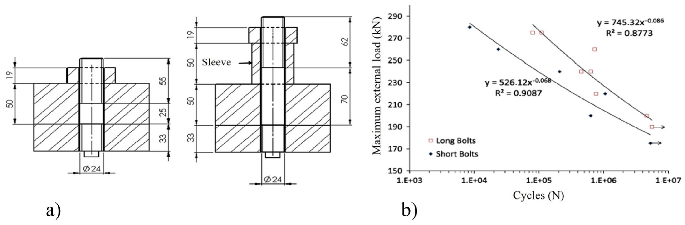
130] investigated the effect of stud length on the fatigue strength of M24x3 class 8.8 by introducing a slim spread sleeve. The study revealed that increasing the length of the fastener, while maintaining the same tightening torque, tends to increase the fatigue strength of the joint (
Figure 26). It indicates that the effect of reducing the bolt stiffness by increasing its length is more pronounced than the effect of reducing the member’s stiffness by introducing a thin spread sleeve.
Liu et al. [
131] developed a model Weibull distribution theory to investigate the effect of bolt diameter on the bearing strength of carbon fiber-reinforced polymer (CFRP) laminates. According to research, the bearing strength of CFRP laminates decreases as the diameter of the bolt hole increases, and vice versa. Moreover, under the same bolt-hole diameter, the change in specimen thickness has no apparent impact on the specimen’s bearing strength. This phenomenon occurs because laminates of two thicknesses have different layup patterns.
The effect of bolt holes on the shear load for a single lap joint was studied. The results revealed the bolt-hole clearance of less than 1 mm could cause stress concentration, and increasing the gap causes a decrease in tension force capacity or axial rigidity. Moreover, it is observed that the maximum shear forces in bolts take place on the middle bolts [
132]. In another study, the effect of bolt diameter, length, and thread pitch on fatigue loading was investigated. Grade 10.9 flange fasteners of the following sizes, M12 × 1.25 × 130, M12 × 1.25 × 80, and M14 × 1.5 × 80, according to the International Organization for Standardization (ISO), were used. The study indicates that a representative S-N curve can be proposed for bolts of the same material in terms of size, length, load amplitude, and varied preload, ranging from elastic to plastic region tightening [
133].
A mathematical expression was derived to predict the behavior of bolts at elevated temperatures. The bolts of different sizes of grades 10.9 and 8.8 were used in heating regions of temperatures up to 500 °C. The results showed that the mechanical properties of both grades remain unchanged at a temperature of 250 °C, and it reduced dramatically when the temperature ranges from 400 to 500 °C. Moreover, grade 10.9 steel bolts, compared with grade 8.8 bolts, had better performance after exposure to the heating–cooling cycle due to their chemical composition [
134].
In another study, researchers used artificial neural networks (ANNs) to create a MATLAB tool capable of estimating the moment-rotation backbone and self-centering behavior of extended endplate connections with shape memory alloy (SMA) bolts. In addition, the research involves conducting optimization studies using a multiobjective genetic algorithm. The objective is to minimize the utilization of materials such as steel and SMA, while simultaneously enhancing the connection-response properties, including stiffness, strength, and ductility. The findings of the study indicate that in order to enhance the moment and rotation capacity of shape memory alloy (SMA) connections, it is necessary to use larger bolt diameters and higher maximum transformation strains for SMA bolts [
135].
The most important results from the studies in this section may be summarized as:
The maximum torque and rotational capacity can be increased by increasing the bolt’s diameter;
The load distribution is more uniform when using larger diameter bolts due to the larger bearing surface;
The bolt and member stiffness increases with the increase in bolt diameter;
The fatigue life of the joint can be increased by increasing the length of the bolt/stud;
The mechanical properties of the bolts decrease at elevated temperatures.
8. Conclusions
Several types of optimization techniques for threaded fasteners have been reviewed. The literature shows that five major optimizing algorithms, i.e., the genetic algorithm, neural networks, Taguchi methods, response surface method (RSM), and design of experiment (DOE), were used to optimize the different parameters of bolted joints. Most of the analytical modeling was performed in MATLAB and Excel, and numerical analysis in the ANSYS and ABAQUS software.
From the existing research, it can be deduced that bolt layout optimization is crucial to obtain a uniform distribution of the load and using fewer bolts to reduce the cost and weight of the system. Layout optimization can be performed for the sake of maintaining stiffness, reducing stresses, or lowering deformations. It is also crucial to reduce the loading scatter and prevent the critical bolt from failing. However, limited literature is available regarding the use of different bolt sizes bearing the same geometry; most researchers have used the same size and bolt grades. In the future, different bolt materials, sizes, and grades can be assessed for joining similar or dissimilar materials, composites, and for plastics.
Great efforts have been made to minimize the stresses at the critical areas of a bolt, i.e., fillet under the head, bolt shank run-out, and first engaged thread. Various new shapes and variable pitches for threads have been introduced instead of given standards to minimize the stress concentration and to distribute the applied load evenly. However, the researchers focused on optimizing the shape, and very few worked on reducing stresses by changing the material’s stiffness. For future cases, stiffness variation and shape optimization can be merged to achieve optimal stresses. Different material processing techniques can also be investigated to improve the mechanical properties by avoiding stress concentration.
To date, different bolt-tightening strategies are available in the literature provided by the standards. Many researchers have developed tightening tools to avoid issues associated with elastic interaction and load scatter. Unfortunately, the available tightening methods are time-consuming, and pre-loads cannot be measured directly. Therefore, time-efficient tightening tools are required with built-in load and torque measuring devices.
Another key point emerging from this review is the need for a proper tightening sequence to avoid preload loss due to the elastic interaction of bolts. Inappropriate tightening sequences cause bolt loss, which leads to fatigue failure. The literature sums up the different tightening sequences that give uniform load distribution and minimize the load scatter. Most of the available literature deals with the tightening sequences of the flanged bolted joints, and very few studies have discussed the tightening of plates, which must be considered in the future.
As for the size and grade of the bolt, the literature highlighted bolts of different sizes and lengths. The bolt size mainly affects the stiffness and load distribution over the clamping members, but larger size bolts can cause an increase in weight and cost. The length of bolts depends on the thickness of the joined plates, but it can be altered by introducing sleeves to improve fatigue life. However, most studies from the literature discussed the same type and material of bolts applied to a single geometry. It could be interesting to investigate bolts of different materials and sizes being applied to the same single geometry.
The designer must account for all the optimization techniques to obtain efficient joints in light of the above. There is a limit to optimizing all parameters analytically and experimentally due to cost and time. Therefore, there is indeed a need for the development of numerical assessment tools that consider all input parameters and enable a fully optimized design.


 ,
, 


