Article

Modeling and Analysis of Metal Liquid Film Flow Characteristics during Centrifugal Spray Forming

1
School of Mechatronics Engineering, Henan University of Science and Technology, Luoyang 471003, China
2
Joint Engineering Research Center for Abrasion Control and Molding of Metal Materials, Henan University of Science and Technology, Luoyang 471003, China
3
School of Materials Science and Engineering, Henan University of Science and Technology, Luoyang 471003, China
*
Authors to whom correspondence should be addressed.
Metals 2023, 13(10), 1687; https://doi.org/10.3390/met13101687
Submission received: 1 September 2023 / Revised: 26 September 2023 / Accepted: 2 October 2023 / Published: 3 October 2023
(This article belongs to the Special Issue Light Alloy and Its Application II)

Abstract

:
Liquid films are an important part of liquid metal granulation in the process of centrifugal spray forming. The size of the granulated particles has an important influence on the density, grain size and microstructure uniformity of the deposited blanks. The particle size is closely related to the flow characteristics of liquid films. Therefore, enhancing our understanding of the flow characteristics of liquid films can provide guidance for forming blanks. In this study, force analysis of a liquid film on the surface of a high-speed rotating centrifugal disc used in centrifugal spray-forming technology was carried out using D’Alembert’s principle and Newton’s law of viscosity. Then, combined with the principle of mass conservation, a theoretical model of the smooth flow of the liquid metal film was established. The experimental values obtained by Leshev were compared with our values to verify the correctness and accuracy of the model. Through the model, the influencing factors of the liquid film flow were obtained, such as the centrifugal disc speed, centrifugal disc radius, inlet volume flow rate and kinematic viscosity. Taking A390 aluminum alloy as the research object, the influence of the process parameters on the thickness, velocity and trajectory of the liquid film was revealed theoretically, and the relationship between the process parameters and the trajectory length and liquid film thickness was clarified. Modeling and analysis can not only help us to understand the flow of a liquid film, but also help us to predict the relevant parameters, which is convenient for the accurate and rapid regulation of the process to obtain the desired flow parameters. Therefore, the research content of this paper is of great significance for the preparation of billets with a uniform microstructure and excellent mechanical properties.

1. Introduction

Centrifugal spray-forming technology uses the centrifugal force provided by a high-speed rotating centrifugal disc to granulate a film-like metal [1,2], and the granulated droplets are deposited on a moving substrate to form a metal blank with a refined microstructure and uniform chemical composition [3,4]. The microstructure and related mechanical properties of the deposited blank [5,6,7] are mainly determined by the size, temperature and speed of the atomized droplets, and the atomization process [8,9,10] is closely related to the flow behavior of the liquid film. Therefore, it is of great significance to study the flow behavior of liquid films for the preparation of high-performance blanks.
It is very difficult to measure the flow behavior of a liquid film on the surface of a high-speed rotating centrifugal disc [11,12,13]. Therefore, research on the flow characteristics of liquid films is mostly carried out using theoretical and simulation methods. Yubin Wang [14] used the method of computational fluid dynamics to analyze the hydrodynamic behavior of a liquid in a rotor–stator spinning disc reactor. The results showed that the average liquid velocity increased with the increase in the rotational speed, volume and radial radius. The average radial velocity increased with the decrease in the rotational speed, volume and radial radius. Zhao [15,16,17] obtained a simplified equation set by analyzing the force of a fluid and combining the dimensionless relationships of the velocity, radius and angular velocity. When solving the equation set, the relationship between the liquid film thickness and velocity and radius was obtained using a discrete method. Based on the order-of-magnitude analysis and the film hypothesis, the Navier–Stokes equation was simplified by Wang Dongxiang [18,19]. A theoretical model of the liquid film flow characteristics in a turntable area after a hydraulic jump was established, and the thickness and velocity of a liquid film after a hydraulic jump were obtained. Sisoev’s study [20] found that air-induced shear force may cause fluctuations in the surface of the film, but that the average liquid film thickness will not change significantly, and the liquid film in the center and edge regions of the turntable has an approximately steady-state flow. In summary, the existing research lacks a detailed exploration of the liquid film flow process. Therefore, the aims of this paper were to study the liquid film flow behavior and reveal the formation mechanism and variation law of the liquid film flow.
It is difficult to obtain the required data using the conventional test equipment for forming liquid films with a high-temperature liquid metal [21], and experimental research encounters problems with high costs and difficulties in traversing a wide range of test parameters. Therefore, a steady-state flow model of a liquid film was established by using D’Alembert’s principle, Newton’s viscosity law and the mass conservation principle. The flow characteristics of the A390 aluminum–silicon alloy were solved and calculated using Matlab software. The influence of the process parameters on the liquid film thickness, velocity and trajectory was revealed, and the relationship between the process parameters and trajectory length and liquid film thickness was clarified. The research results can not only help us to understand the flow behavior of the liquid film, but also predict the relevant parameters. The predicted values can provide a theoretical basis for obtaining the required flow parameters and lay a foundation for the study of liquid film granulation into particles.

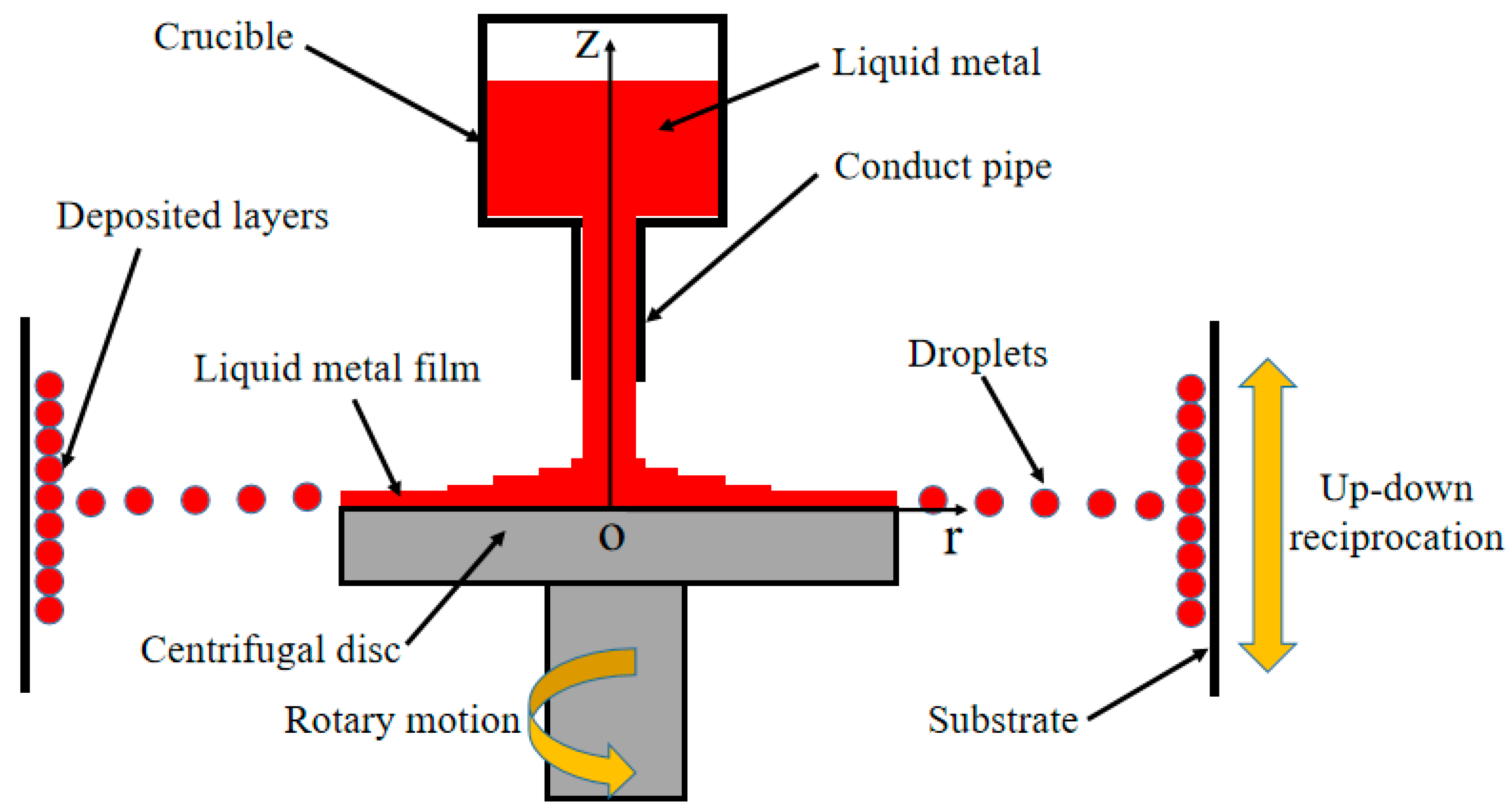
2. Principle and Condition Assumption of Centrifugal Spray-Forming Technology

2.1. Formation Principle of Liquid Metal Film

Figure 1 is a schematic diagram of centrifugal spray deposition for blank preparation [22]. The centrifugal force provided by the liquid metal centrifugal disc atomizes the film-like metal, and the atomized droplets are deposited on a moving substrate in order to prepare a blank with a certain size. For the convenience of expression and subsequent calculation, the reference frame is fixed on the centrifugal disc, and the cylindrical coordinate system r θ z is introduced [23,24,25]. The coordinate origin of the cylindrical coordinate system coincides with the center of the centrifugal disc, as shown in Figure 1. The liquid flows vertically along the negative direction of the z-axis to the surface of the centrifugal disc rotating around itself at an angular velocity and rapidly spreads into the liquid film under the action of centrifugal force. In a specific flow state, there will be a hydraulic jump phenomenon. Because the liquid flow near the hydraulic jump is in a strong turbulent state, it is difficult to theoretically characterize the liquid film flow in the hydraulic jump region. Therefore, this paper aimed to conduct a theoretical analysis of liquid film flow with a steady-state flow.

2.2. Condition Hypothesis

The molten metal is regarded as a Newtonian, incompressible, isothermal fluid [26], and the spreading process of the liquid film is assumed to be as follows [17,18,27]:
(a)
The temperature of the liquid film on the surface of the centrifugal disc does not change.
(b)
Considering that the liquid film is thin, the internal pressure of the liquid film and the pressure on the surface of the liquid film are regarded as the environmental pressure.
(c)
The liquid film has a steady-state axisymmetric flow, so the velocity and pressure do not change with θ .
(d)
The axial velocity is much smaller than the radial and circumferential velocities, so the influence of the axial velocity of the liquid film is ignored.
(e)
There is no slip between the liquid film and the surface of the centrifugal disc, that is, the contact part of the liquid film and the centrifugal disc rotates with the centrifugal disc.
(f)
The gravity and other inertial forces on the liquid film on the centrifugal plate are neglected compared with the centrifugal force and viscous force.

3. Modeling of Liquid Film Flow Characteristics

The main forms of motion of the liquid film on the centrifugal disc are circular motion along the disc surface and linear motion sliding from the center to the edge of the disc. A fluid element is taken at any radial coordinate r , circumferential coordinate θ and axial coordinate z . The radial size of the fluid element is d r , the circumferential size is r d θ and the thickness is d z . The volume of the fluid element is as follows:
d V = r d θ d r d z
Figure 2 is a schematic diagram of the fluid element motion on the surface of the centrifugal disc. The coordinate system r - θ - z rotates with the centrifugal disc, and the motion and force of the liquid film correspond to the dynamic coordinate system (non-inertial system). According to D’Alembert’s principle, the centrifugal force d F on the fluid element is as follows:
d F = ρ [ w × ( w × r ) + 2 w × u θ ] d V
where F is the centrifugal force (vector), N ; ρ is the density of the liquid metal, kg / m 3 ; w is the rotation angular velocity (vector), rad / s ; u θ is the relative circumferential velocity (vector), m / s ; r is the radial position (vector), m ; w × ( w × r ) is the implicated acceleration; and 2 w × u θ is the Coriolis acceleration.
The centrifugal force of the fluid element is decomposed along the radial and circumferential directions, and the formulas of the radial component d F r and circumferential component d F θ are obtained as follows:
d F r = ρ ( r w 2 + 2 w u θ ) d V
d F θ = 2 ρ w u r d V
where u r and u θ are the radial velocity and circumferential velocity of the fluid element relative to the centrifugal disc, m / s ; w is the rotation angular velocity of the centrifugal disc, rad / s ; and F r and F θ are the radial component and circumferential component of the centrifugal force, N .
In practice, the circumferential velocity of the fluid element is much smaller than that of the centrifugal disc [24]. Therefore, the influence of u θ can be neglected, and d F r is approximately as follows:
d F r ρ r w 2 d V
According to Newton’s law of viscosity and assumptions, the following formulas can be obtained:
d P θ = d P r = 0
μ u r θ = τ θ r
μ u r z = τ z r
μ u θ z = τ z θ
In Formulas (7)–(9), τ is the shear stress, N, where the first subscript letter indicates the direction perpendicular to the surface, and the second subscript letter indicates the stress direction, where τ θ r = 0 ; μ is the dynamic viscosity of the liquid, Pa · s .
The force analysis of the fluid element in the radial and tangential directions is shown in Figure 3. The force balance equation of the fluid element can be obtained through analysis.
d F r + ( τ z r + d τ z r ) r d r d θ τ z r r d r d θ = 0
d F θ + ( τ z θ + d τ z θ ) r d r d θ τ z θ r d r d θ = 0
By substituting F r , F θ , τ z r and τ z θ into Formulas (10) and (11), the equations of the radial velocity and circumferential velocity can be obtained.
μ 2 u r z 2 + ρ r w 2 = 0
μ 2 u θ z 2 2 ρ w u r = 0
On the surface of the centrifugal disc, that is, z = 0 , there is no slip between the centrifugal disc and the liquid film. The boundary conditions are as follows:
u r = 0   , u θ = 0
On the surface of the liquid film, that is, z = h , the shear force between the liquid film and the air is zero, and the boundary conditions are as follows:
u r z = 0 , u θ z = 0
According to Equations (12)–(15), the radial velocity and circumferential velocity of the liquid film on the surface of the centrifugal disc are as follows:
u r = ρ r w 2 μ ( h z z 2 2 )
u θ = ρ 2 r w 3 12 μ 2 ( 8 h 3 z 4 h z 3 + z 4 )
The negative sign of the circumferential velocity in Formula (17) indicates that the direction of motion is opposite to the direction of rotation of the centrifugal disc.
Because the actual liquid film is thin, the liquid film on the centrifugal disc can be treated as a small cylinder. According to the principle of mass conservation, for any radius r on the surface of the disk, the volume flow rate Q can be expressed as follows:
0 h 2 π r u r d z = Q
where Q is the volume flow rate of the liquid, m 3 / s , and h is the liquid film thickness, m .
Combined with Formulas (16) and (18), the calculation formula for the liquid film thickness can be obtained as follows:
h = ( 3 μ Q 2 π ρ r 2 w 2 ) 1 3
From the relationship between the dynamic viscosity and kinematic viscosity, the following can be obtained:
h = ( 3 ν Q 2 π r 2 w 2 ) 1 3
ν = μ ρ
where ν is the kinematic viscosity of the liquid, m 2 / s .
The overall flow trend of the liquid metal on the centrifugal disc is described by the average radial velocity and circumferential slip. The average radial velocity and average circumferential velocity of the liquid film are as follows:
u r a = Q 2 π r h = ( w 2 Q 2 12 π 2 ν r ) 1 3
u θ a = 0 h u θ d z h = 3 r w 5 ( 2 Q 2 3 π 2 ν w r 4 ) 2 3
where u r a is the average radial velocity of the liquid film, m / s , and u θ a is the average circumferential velocity of the liquid film, m / s .
The circumferential slip is expressed as the ratio of the circumferential velocity of the liquid film to the circumferential velocity of the centrifugal disc.
ϕ = | u θ a | r w = 3 5 ( 2 Q 2 3 π 2 ν w r 4 ) 2 3
where ϕ is the circumferential slip.
The change in the vector diameter with time is the velocity, and the time required for the fluid to move from the center of the centrifugal disc to any position can be obtained by using the velocity as an intermediate variable. Furthermore, the rotation angle θ and the trajectory length S can be obtained.
u r a = d r d t = ( w 2 Q 2 12 π 2 ν r ) 1 3
t L = o r ( 12 π 2 ν r w 2 Q 2 ) 1 3 d r = 3 4 ( 12 π 2 ν w 2 Q 2 ) 1 3 r 4 3
θ = t L w = 3 4 ( 12 π 2 ν w Q 2 ) 1 3 r 4 3
S = o r r w t L d r = 9 40 ( 12 π 2 ν w Q 2 ) 1 3 r 10 3
where t L is the time it takes the liquid film to spread from the center to the edge, s ; θ is the rotation angle of the liquid film spreading from the center to the edge, rad ; and S is the length of the liquid film trajectory, m.

4. Numerical Experiment

4.1. Model Validation

In the process of centrifugal granulation, the thickness of the liquid film on the surface of the centrifugal disc is generally about several hundred microns, and it is difficult to accurately measure it using conventional methods. Leshev [25] used the probe method to measure the thickness of a liquid film on the surface of an entire turntable. The experimental conditions are shown in Table 1. Figure 4 shows a comparison between the liquid film thickness calculated using Formula (20) and Leshev’s measurement results [25]. At the edge of the centrifugal disc, the prediction result of the liquid film thickness has high accuracy, which is in good agreement with the experimental measurement, and the error is large near the center of the rotating disc. The model established in this paper is mainly used to predict the liquid film parameters at the edge of the centrifugal disc, so it is considered that the model can be used to predict the flow characteristics of the liquid film.

4.2. Numerical Calculation

Due to the high silicon content of the Al–Si alloy, under the conventional casting process, the primary silicon exhibits a variety of morphologies, such as star, polygon, plate and feather morphologies, and the eutectic silicon is coarse and needle-like [28,29,30], which easily leads to premature crack initiation and tensile fracture, resulting in a decrease in the mechanical properties. In order to overcome the above shortcomings, the centrifugal spray-forming process of the Al–Si alloy was explored. Therefore, the A390 aluminum–silicon alloy was taken as the research object. The chemical composition of A390 is shown in Table 2. When the temperature is in the range of 660 °C to 1000 °C, the kinematic viscosity of the molten A390 changes between 3.8 × 10⁻⁷ m2/s and 11.4 × 10⁻⁷ m2/s.
The parameters used for the numerical calculation are shown in Table 3. In the calculation of Formulas (20), (22) and (24), each formula calculates 15 sets of data, that is, two of the three variables are kept unchanged, with only one of them changed, and the influence of this changed parameter on the liquid film characteristics is analyzed.
In this paper, MATLAB software was used to solve the steady-state model. MATLAB is a commercial mathematics software produced by MathWorks Company in the United States. The version used in this article was MATLAB 9.11. In the calculation, the relevant parameters were input first, then the liquid film thickness was calculated, and finally the calculation speed, trajectory length, etc., were calculated.

5. Results and Discussion

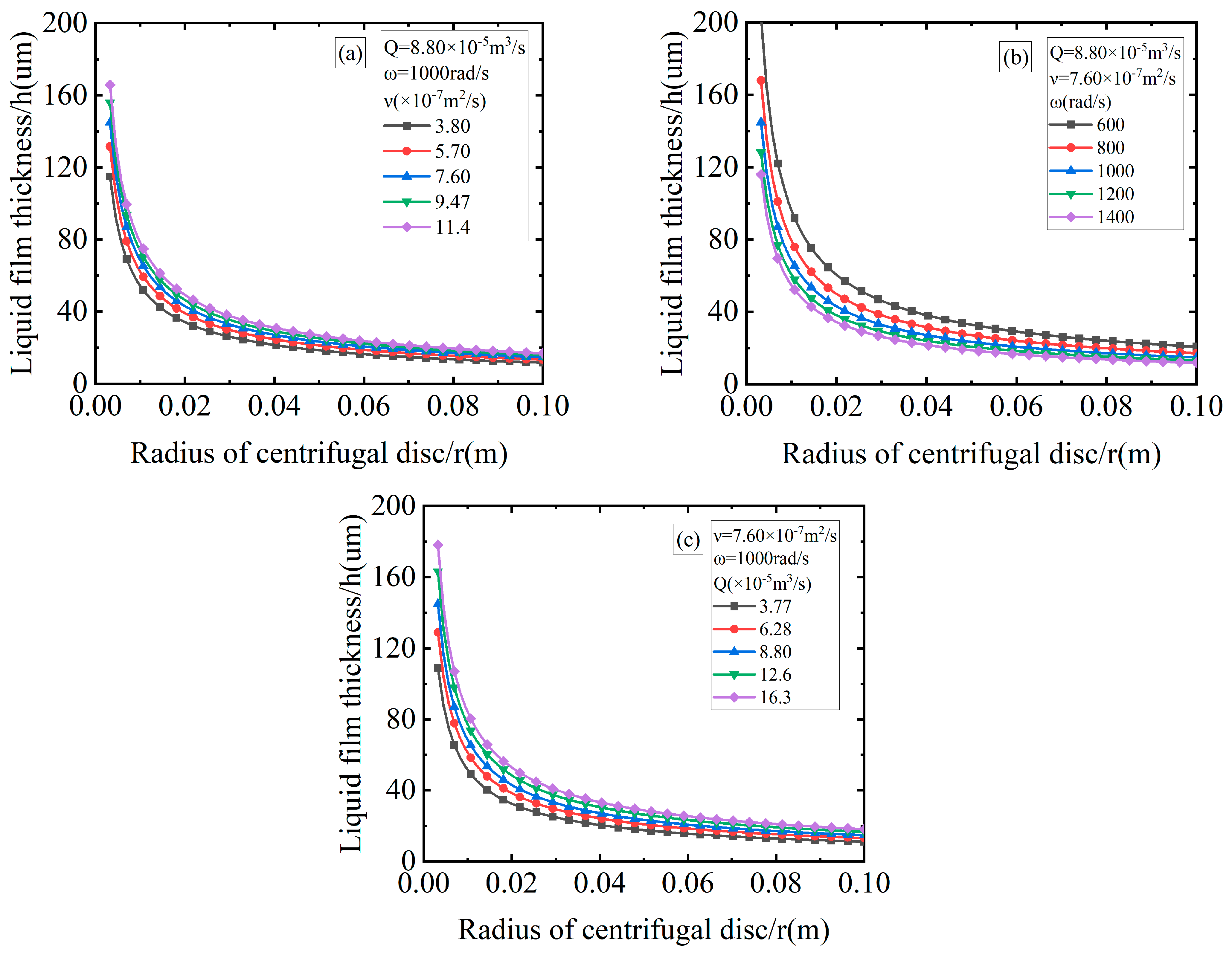
5.1. Analysis and Discussion of Liquid Film Thickness

Figure 5a–c shows the distribution of the liquid film thickness along the radial direction under different kinematic viscosities, different centrifugal disc speeds and different volume flow rates. It can be seen in the figure that the liquid film is thicker at a position closer to the rotation axis, which means that the liquid film has not yet fully spread and is present on the surface of the centrifugal disc in the form of a liquid column. As the liquid film flows outwards along the radial direction, the thickness of the liquid film decreases rapidly and then slowly, which means that the fluid is in a stable flow state. For any specified radius, the liquid film thickness increases with the increase in the volume flow rate and kinematic viscosity, and decreases with the increase in the centrifugal disc rotation speed. When the radius is 0.1 m, as the kinematic viscosity increases from 3.80 × 10⁻⁷ m2/s to 11.4 × 10⁻⁷ m2/s, the liquid film thickness increases from 11.7 μm to 16.9 μm; as the rotation speed of the centrifugal disc increases from 600 rad/s to 1400 rad/s, the liquid film thickness decreases from 20.7 μm to 11.8 μm; and as the volume flow rate increases from 3.77 × 10 −5 m3/s to 16.3 × 10⁻⁵ m3/s, the liquid film thickness increases from 11.1 μm to 18.1 μm. By quantifying the thickness of the liquid film at the edge, it can be concluded that the change in the rotational speed has a more significant effect on the thickness of the liquid film, which indicates that the centrifugal field provided by the centrifugal force at the edge plays a leading role in the spreading of the liquid film.

5.2. Analysis and Discussion of Average Radial Velocity of the Liquid Film

Figure 6a–c shows the distribution of the average radial velocity along the radial direction under different kinematic viscosities, different centrifugal disc speeds and different volume flow rates. It can be seen in the diagram that the average radial velocity value is higher at positions closer to the rotation axis. When the liquid metal hits the center of the centrifugal disc from the inlet, the direction of the fluid’s motion changes rapidly in a short period of time, making the average radial velocity value relatively high. As the liquid film spreads along the radial direction, the average radial velocity first decreases rapidly and then slowly. For any specified radius, the average radial velocity increases with the increase in the volume flow rate, and decreases with the increase in the kinematic viscosity and rotation speed of the centrifugal disc. When the radius is 0.1 m, as the kinematic viscosity increases from 3.80 × 10⁻⁷ m2/s to 11.4 × 10⁻⁷ m2/s, the average radial velocity decreases from 11.9 m/s to 8.3 m/s; as the rotation speed of the centrifugal disc increases from 600 rad/s to 1400 rad/s, the average radial velocity increases from 6.8 m/s to 11.9 m/s; and as the volume flow rate increases from 3.77 × 10⁻⁵ m3/s to 16.3 × 10⁻⁵ m3/s, the average radial velocity increases from 5.4 m/s to 14.4 m/s. By quantifying the thickness of the liquid film at the edge, it can be concluded that the change in the volume flow rate has a more significant effect on the average radial velocity, which indicates that the overflow rate on the surface of the centrifugal disc increases at a large volume flow rate, the energy obtained by the liquid film from the centrifugal disc increases and the spreading to the edge is accelerated.

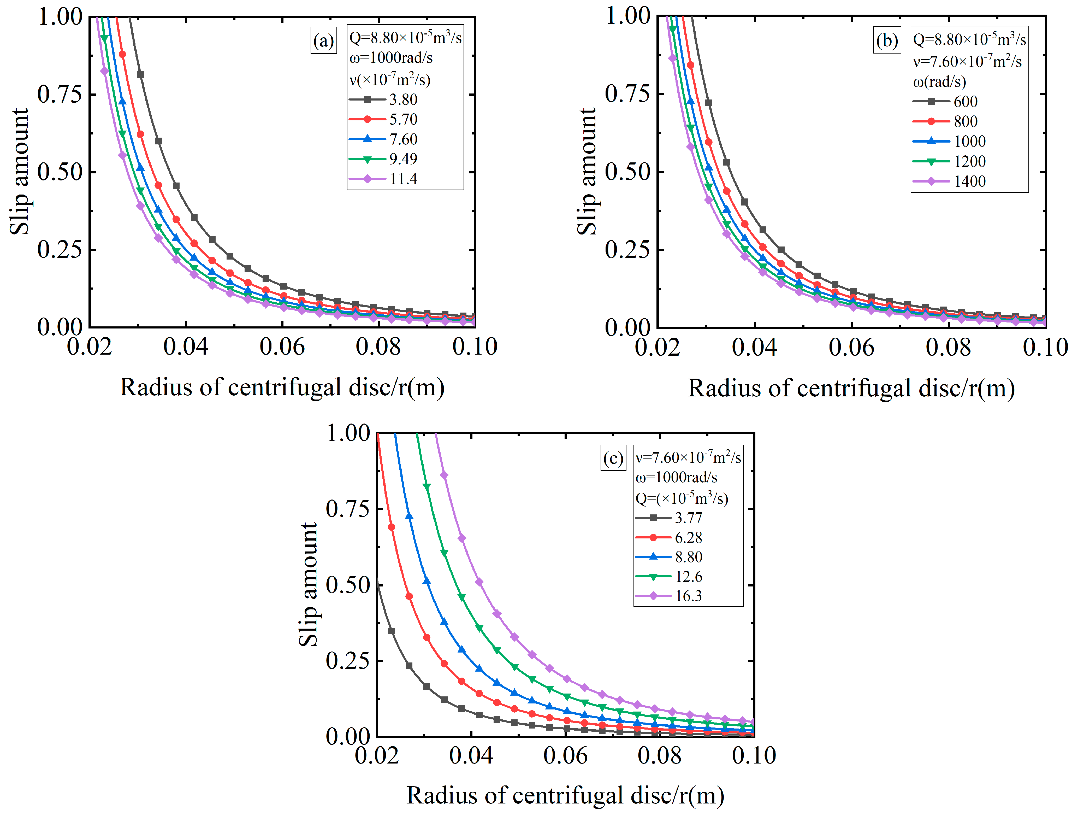
5.3. Analysis and Discussion of Circumferential Slip

Figure 7 a–c shows the distribution of the circumferential velocity slip along the radial direction under different kinematic viscosities, different centrifugal disc speeds and different volume flow rates. It can be seen in the diagram that the closer to the rotation axis, the higher the degree of slip; this is because when the liquid metal hits the center of the centrifugal disc from the inlet, the direction of motion of the fluid changes to the radial direction, and the circumferential component is almost zero. As the liquid film spreads outwards along the radial direction, the sliding degree first decreases rapidly and then slowly to a certain value and remains unchanged, which means that the force in the circumferential direction of the liquid film reaches the viscous force limit. For any specified radius, the degree of slip increases with the increase in the volume flow rate, and decreases with the increase in the rotational speed and kinematic viscosity of the centrifugal disc. When the radius is 0.1 m, as the kinematic viscosity increases from 3.80 × 10⁻⁷ m2/s to 11.4 × 10⁻⁷ m2/s, the slip decreases from 3.44% to 1.66%; as the rotational speed of the centrifugal disc increases from 600 rad/s to 1400 rad/s, the slip decreases from 3.05% to 1.73%; and as the volume flow rate increases from 3.77 × 10⁻⁵ m3/s to 16.3 × 10⁻⁵ m3/s, the circumferential slip increases from 0.7% to 4.9%. By quantifying the thickness of the liquid film at the edge, it can be concluded that the change in the volume flow rate has a more significant effect on the circumferential slip. At the same time, according to the small slip at the edge, the tangential velocity of the liquid film can be approximately considered to be consistent with the tangential velocity of the centrifugal disc.

5.4. Analysis and Discussion of Liquid Film Trajectory

Figure 8a–c shows the trajectory of the liquid film on the surface of the centrifugal disc under different kinematic viscosities, different centrifugal disc speeds and different volume flow rates. In the trajectory diagram, it can be seen that the trajectory of the liquid film is a spiral line. The length of the liquid film trajectory increases with the increase in the kinematic viscosity and rotational speed of the centrifugal disc, and decreases with the increase in the volume flow rate. When the radius is 0.1 m, as the kinematic viscosity increases from 3.80 × 10⁻⁷ m2/s to11.4 × 10−7 m2/s, the rotation angle increases from 6.26 rad to 9.03 rad; as the rotation speed of the centrifugal disc increases from 600 rad/s to 1400 rad/s, the rotation angle increases from 6.65 rad to 8.82 rad; and as the volume flow rate increases from 3.77 × 10⁻⁵ m3/s to 16.3 × 10⁻⁵ m3/s, the rotation angle decreases from 13.87 rad to 5.22 rad. By quantifying the rotation angle at the edge, it can be concluded that the change in the volume flow has a more significant effect on the rotation angle; this is because the larger the volume flow, the greater the radial velocity and circumferential slip, and the rotation angle is reflected in the trajectory.

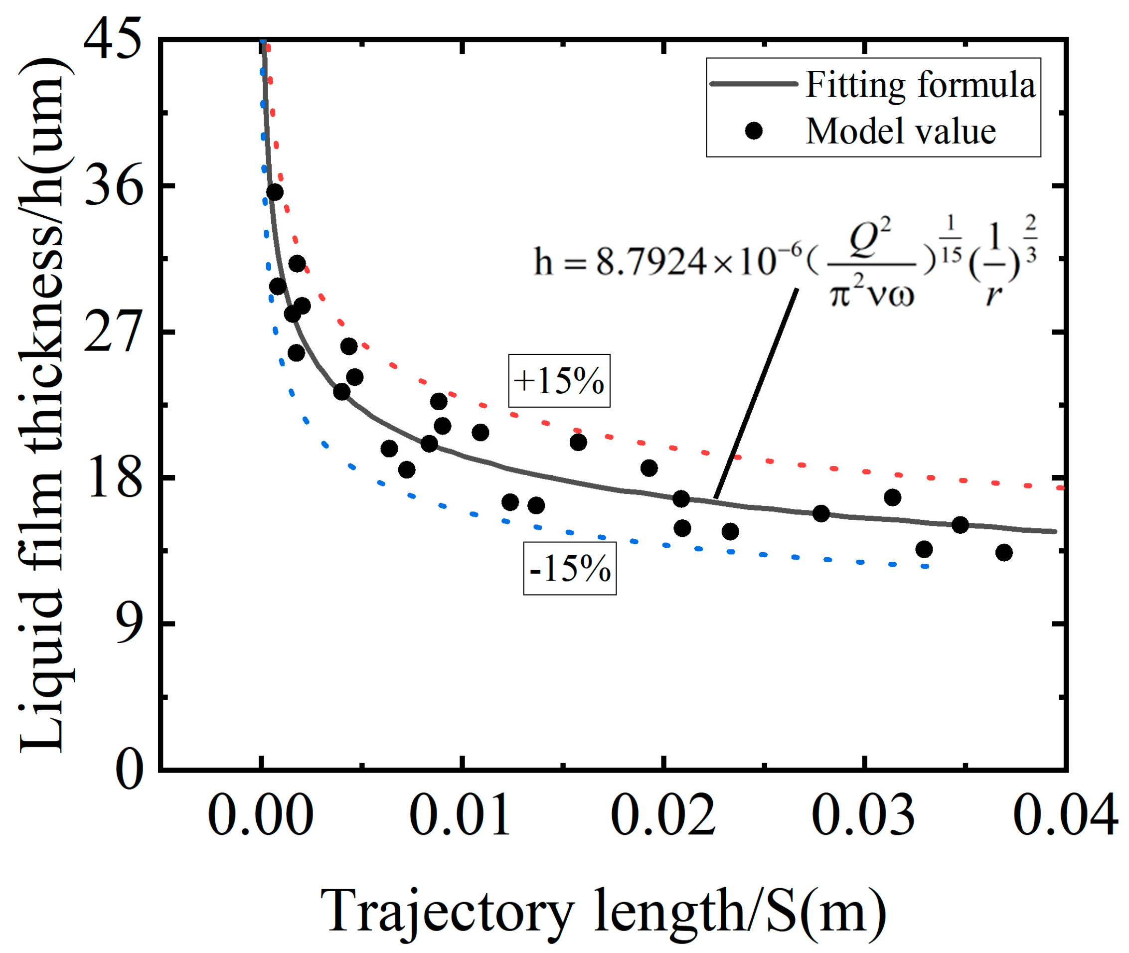
5.5. The Relationship between Liquid Film Thickness and Trajectory Length

Formula (29) can be obtained through the nonlinear fitting of the liquid film thickness and trajectory length.
h = 8.7924 × 10 6 ( Q 2 π 2 ν ω ) 1 15 ( 1 r ) 2 3
Figure 9 shows the relationship between the liquid film thickness and the trajectory length. The thickness of the liquid film decreases with the increase in the length of the trajectory, and the error between the fitted value and the model value is controlled within ±15%. The formula can be used for the design and optimization of the centrifugal disc structure. In the design and optimization, the trajectory length of the liquid film on the surface of the centrifugal disc can be increased to obtain a thinner liquid film, and then a uniform atomized droplet can be obtained.

6. Conclusions

According to the principle of liquid film formation, the cylindrical coordinate system r θ z was introduced. Force analysis of the fluid element was carried out using D’Alembert’s principle and Newton’s viscosity law, and the force balance equation was established. The model of the flow characteristics of the liquid film was obtained through combination with the principle of mass conservation. The model can not only help us to understand how the liquid film flows in the centrifugal disc, but can also help us to predict the relevant parameters. The predicted values provide a theoretical basis for obtaining the required flow parameters and lay a foundation for the subsequent study of liquid film atomization into particles. On this basis, molten A390 aluminum alloy was modeled and analyzed, and the results showed were as follows:
1. The trajectory of the liquid film formed by the liquid metal on the surface of the rotating centrifugal disc is a spiral line. When moving to the edge, the thickness of the liquid film along the radial direction first quickly and then slowly decreases. After the flow enters a stable state, the thickness of the liquid film remains basically unchanged. At the same time, the tangential velocity of the liquid film at the edge can be approximately considered to be the same as the tangential velocity of the centrifugal disc.
2. The effects of the centrifugal disc speed, kinematic viscosity and volume flow rate on the flow characteristics of the liquid film are different. The liquid film thickness increases with an increase in the volume flow rate and kinematic viscosity, and decreases with an increase in the centrifugal disc rotation speed. The average radial velocity and circumferential slip increase with an increase in the volume flow rate, and decrease with an increase in the kinematic viscosity and rotation speed of the centrifugal disc. The trajectory length increases with an increase in the kinematic viscosity and centrifugal disc speed, and decreases with an increase in the volume flow rate.
3. The nonlinear relationship between the thickness of the liquid film and the length of the trajectory was obtained through data fitting. The relationship is as follows:
h = 8.7924 × 10 6 ( Q 2 π 2 ν ω ) 1 15 ( 1 r ) 2 3 .

Author Contributions

Conceptualization, P.L.; methodology: P.L. and B.S.; software, P.L. and L.Y.; validation, P.L.; formal analysis, S.W.; resources, L.Y. and B.S.; writing—original draft preparation, P.L.; writing—review and editing, S.W. and X.L.; visualization, S.T.; supervision, X.L.; project administration, P.L.; funding acquisition, S.W. All authors have read and agreed to the published version of the manuscript.

Funding

This work was financially supported by the National Key R&D Program of China (2020YFB2008400).

Institutional Review Board Statement

Not applicable.

Informed Consent Statement

Not applicable.

Data Availability Statement

Not applicable.

Conflicts of Interest

The authors declare no conflict of interest.

Nomenclature

r radial coordinate/( m )
θ circumferential coordinate/( rad )
z axial coordinate/( m )
d V volume of the fluid element/( m 3 )
d F centrifugal force of the fluid element (vector)/( N )
F centrifugal force (vector)/( N )
ρ density of liquid metal/( kg / m 3 )
w rotation angular velocity (vector)/( rad )
u θ circumferential velocity of the fluid element relative to the centrifugal disc(vector)/( m / s )
r radial position (vector)/( m )
d F r radial force of the fluid element/( N )
d F θ circumferential force of the fluid element/( N )
F r radial component of centrifugal force/( N )
F θ circumferential component of centrifugal force/( N )
w rotation angular velocity of the centrifugal disc/( rad / s )
u r radial velocity of the fluid element relative to the centrifugal disc/( m / s )
u θ circumferential velocity of the fluid element relative to the centrifugal disc/( m / s )
μ dynamic viscosity of the liquid/( Pa · s )
ν kinematic viscosity of the liquid/( m 2 / s )
τ shear stress/( N )
h liquid film thickness/( m )
Q volume flow rate of liquid/( m 3 / s )
u r a average radial velocity of the liquid film/( m / s )
u θ a average circumferential velocity of the liquid film/( m / s )
ϕ circumferential slip
t L Time from center to edge/( s )
S trajectory length/( m )

References

  1. Mandal, S.; Sadeghianjahromi, A.; Wang, C.-C. Experimental and numerical investigations on molten metal atomization techniques–A critical review. Adv. Powder Technol. 2022, 33, 103809. [Google Scholar] [CrossRef]
  2. Ravry, B.; Mathieu, A.; Bernard, F.; Demoisson, F. Atomization regime observation and characterization of an atomized pure zinc rod during centrifugal atomization using a LASER beam. Powder Technol. 2023, 415, 118139. [Google Scholar] [CrossRef]
  3. Hussain, S.; Cui, C.; Mädler, L.; He, L.; Uhlenwinkel, V. Effect of hot gas atomization on spray forming of steel tubes using a close-coupled atomizer (CCA). J. Mater. Process. Technol. 2020, 282, 116677. [Google Scholar] [CrossRef]
  4. Chourasiya, S.K.; Gautam, G. Enhancing the microstructure and tribological performance of spray formed Al alloy by cryorolling. Silicon 2021, 13, 2857–2868. [Google Scholar] [CrossRef]
  5. Rojas, O.; Muñoz, R.; Holguín, J.D.; López, M.E.; Ageorges, H.; Vargas, F. Porosity formation phenomena in glass particles atomised by oxyacetylene flame-spraying: Effect of feedstock powders and atomisation conditions. Ceram. Int. 2023, 49, 14512–14524. [Google Scholar] [CrossRef]
  6. Yin, C.; Lu, Z.; Wei, X.; Yan, B.; Yan, P. High Bending Strength Hypereutectic Al-22Si-0.2Fe-0.1Cu-Re Alloy Fabricated by Selective Laser Melting. Metals 2021, 11, 528. [Google Scholar] [CrossRef]
  7. Dash, S.S.; Chen, D. A Review on Processing–Microstructure–Property Relationships of Al-Si Alloys: Recent Advances in Deformation Behavior. Metals 2023, 13, 609. [Google Scholar] [CrossRef]
  8. Mantripragada, V.T.; Sarkar, S. Prediction of drop size from liquid film thickness during rotary disc atomization process. Chem. Eng. Sci. 2017, 158, 227–233. [Google Scholar] [CrossRef]
  9. Palanti, L.; Puggelli, S.; Langone, L.; Andreini, A.; Reveillon, J.; Duret, B.; Demoulin, F.X. An attempt to predict spray characteristics at early stage of the atomization process by using surface density and curvature distribution. Int. J. Multiph. Flow 2022, 147, 103879. [Google Scholar] [CrossRef]
  10. Gao, Y.; Zhao, Y.; Zhang, G.; Yin, F.; Zhao, G.; Guo, H. Preparation and characterization of spherical diamond magnetic abrasive powder by atomization process. Diam. Relat. Mater. 2020, 102, 107658. [Google Scholar] [CrossRef]
  11. Cherdantsev, A.; Bobylev, A.; Guzanov, V.; Kvon, A.; Kharlamov, S. Measuring liquid film thickness based on the brightness level of the fluorescence: Methodical overview. Int. J. Multiph. Flow 2023, 168, 104570. [Google Scholar] [CrossRef]
  12. Wu, W.; Kong, S.; Xu, X.; Tao, J.; Li, C.; Wang, J.; Su, M.; Yang, H. Simultaneous measurement of liquid film thickness and temperature on metal surface. Spectrochim. Acta Part A Mol. Biomol. Spectrosc. 2021, 257, 119804. [Google Scholar] [CrossRef]
  13. Payri, R.; Salvador, F.J.; Carreres, M.; Moreno-Montagud, C. A computational methodology to account for the liquid film thickness evolution in Direct Numerical Simulation of prefilming airblast atomization. Int. J. Multiph. Flow 2023, 161, 104403. [Google Scholar] [CrossRef]
  14. Wang, Y.; Chen, M.; Jin, Y.; Ouguang, Y.; Li, J. CFD simulation of liquid flow characteristics in a rotor-stator spinning disc reactor. J. Taiwan Inst. Chem. Eng. 2020, 115, 20–27. [Google Scholar] [CrossRef]
  15. Zhao, Y.Y. Analysis of flow development in centrifugal atomization: Part I. Film thickness of a fully spreading melt. Model. Simul. Mater. Sci. Eng. 2004, 12, 959–971. [Google Scholar] [CrossRef]
  16. Zhao, Y.Y. Analysis of flow development in centrifugal atomization: Part II. Disintegration of a non-fully spreading melt. Model. Simul. Mater. Sci. Eng. 2004, 12, 973–983. [Google Scholar] [CrossRef]
  17. Zhao, Y.Y.; Jacobs, M.H.; Dowson, A.L. Liquid flow on a rotating disk prior to centrifugal atomization and spray deposition. Metall. Mater. Trans. B 1998, 29, 1357–1369. [Google Scholar] [CrossRef]
  18. Wang, D.; Ling, X.; Peng, H. Theoretical analysis of free-surface film flow on the rotary granulating disk in waste heat recovery process of molten slag. Appl. Therm. Eng. 2014, 63, 387–395. [Google Scholar] [CrossRef]
  19. Wang, D.; Ling, X.; Peng, H. Simulation of ligament mode breakup of molten slag by spinning disk in the dry granulation process. Appl. Therm. Eng. 2015, 84, 437–447. [Google Scholar] [CrossRef]
  20. Sisoev, G.M.; Matar, O.K.; Lawrence, C.J. Axisymmetric wave regimes in viscous liquid film flow over a spinning disk. J. Fluid Mech. 2003, 495, 385–411. [Google Scholar] [CrossRef]
  21. Ogura, T.; Matsumoto, T.; Miwa, S.; Mori, M.; Hibiki, T. Experimental study on molten metal spreading and deposition behaviors. Ann. Nucl. Energy 2018, 118, 353–362. [Google Scholar] [CrossRef]
  22. Li, P.; Wei, S.; Lei, X.; Yang, L.; Sun, B. Study on Flight Dynamics and Heat Transfer Solidification of Metal Droplets during Centrifugal Spray Deposition Forming Process. Metals 2023, 13, 1446. [Google Scholar] [CrossRef]
  23. Matar, O.K.; Lawrence, C.J.; Sisoev, G.M. The flow of thin liquid films over spinning disks: Hydrodynamics and mass transfer. Phys. Fluids 2005, 17, 412. [Google Scholar] [CrossRef]
  24. Myers, T.G.; Lombe, M. The importance of the Coriolis force on axisymmetric horizontal rotating thin film flows. Chem. Eng. Process. Process Intensif. 2005, 45, 90–98. [Google Scholar] [CrossRef]
  25. Leshev, I.; Peev, G. Film flow on a horizontal rotating disk. Chem. Eng. Process. Process Intensif. 2003, 42, 925–929. [Google Scholar] [CrossRef]
  26. Ho, K.H.; Zhao, Y.Y. Modelling thermal development of liquid metal flow on rotating disc in centrifugal atomisation. Mater. Sci. Eng. A 2004, 365, 336–340. [Google Scholar] [CrossRef]
  27. Sun, H.; Chen, G.; Wang, L.; Wang, F. Ligament and Droplet Generation by Oil Film on a Rotating Disk. Int. J. Aerosp. Eng. 2015, 2015, 1–14. [Google Scholar] [CrossRef]
  28. Zykova, A.; Martyushev, N.; Skeeba, V.; Zadkov, D.; Kuzkin, A. Influence of W addition on microstructure and mechanical properties of Al-12% Si alloys. Materials 2019, 12, 981. [Google Scholar] [CrossRef]
  29. Li, Q.; Xia, T.; Lan, Y.; Zhao, W.; Fan, L.; Li, P. Effect of rare earth cerium addition on the microstructure and tensile properties of hypereutectic Al–20% Si alloy. J. Alloys Compd. 2013, 562, 25–32. [Google Scholar] [CrossRef]
  30. Li, C.; Zhang, X.; Guo, Z.; Li, L.; Shan, Q.; Li, Z. Multi-Phase Structure Control and Interfacial Investigation of TiB2/Hypereutectic Al-Si Alloy. Metals 2023, 13, 933. [Google Scholar] [CrossRef]
Figure 1. Schematic diagram of centrifugal spray deposition for blank preparation.
Metals 13 01687 g001
Figure 2. Schematic diagram of fluid element motion on the surface of the centrifugal disc: (a) side view; (b) top view.
Metals 13 01687 g002
Figure 3. Fluid element force analysis.
Metals 13 01687 g003
Figure 4. Values predicted by the model compared with the experimental values obtained by Leshev [25].
Metals 13 01687 g004
Figure 5. Distribution of liquid film thickness along the radial direction: (a) different kinematic viscosities; (b) different centrifugal disc speeds; (c) different volume flow rates.
Metals 13 01687 g005
Figure 6. Average radial velocity distribution along the radial direction: (a) different kinematic viscosities; (b) different centrifugal disc speeds; (c) different volume flow rates.
Metals 13 01687 g006
Figure 7. Circumferential slip distribution along the radial direction: (a) different kinematic viscosities; (b) different centrifugal disc speeds; (c) different volume flow rates.
Metals 13 01687 g007
Figure 8. Trajectory of liquid film motion: (a) different kinematic viscosities; (b) different centrifugal disc speeds; (c) different volume flow rates.
Metals 13 01687 g008
Figure 9. Relationship between liquid film thickness and trajectory length.
Metals 13 01687 g009
Table 1. Experimental conditions used by Leshev [25].
Working Fluid R / ( m ) ω / ( rad / s ) Q / ( × 10 6 m 3 / s ) ν / ( × 10 7 m 2 / s )
Water0.210.475.331.01
30% glycerol0.210.475.336.25
50% glycerol0.210.475.3310.63
Table 2. A390 chemical constituents (wt%).
Element NameSiFeCuMnMgZnTiAl
Context17.00.54.50.10.550.10.2Balance
Table 3. Parameters of the numerical calculation.
R / ( m ) ω / ( rad / s ) Q / ( × 10 5 m 3 / s ) ν / ( × 10 7 m 2 / s )
0.16003.773.80
0.18006.285.70
0.110008.807.60
0.1120012.69.47
0.1140016.311.4
Disclaimer/Publisher’s Note: The statements, opinions and data contained in all publications are solely those of the individual author(s) and contributor(s) and not of MDPI and/or the editor(s). MDPI and/or the editor(s) disclaim responsibility for any injury to people or property resulting from any ideas, methods, instructions or products referred to in the content.

