
Effects of Graphite Particle Content and Holding Time on the Microstructure and Mechanical Properties of the Graphite/AZ91D Composite
 , , ,
, , ,
Abstract
:1. Introduction
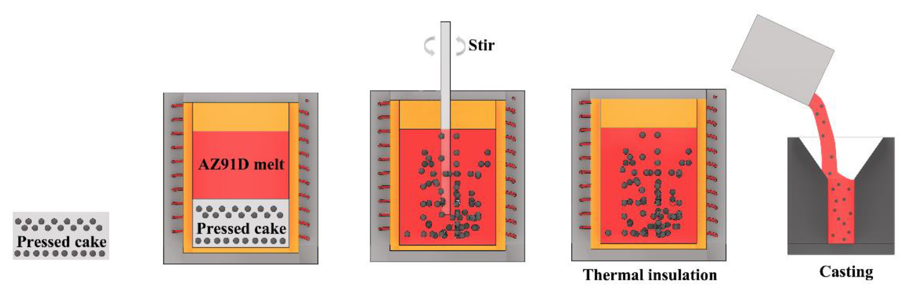
2. Methodology
3. Results
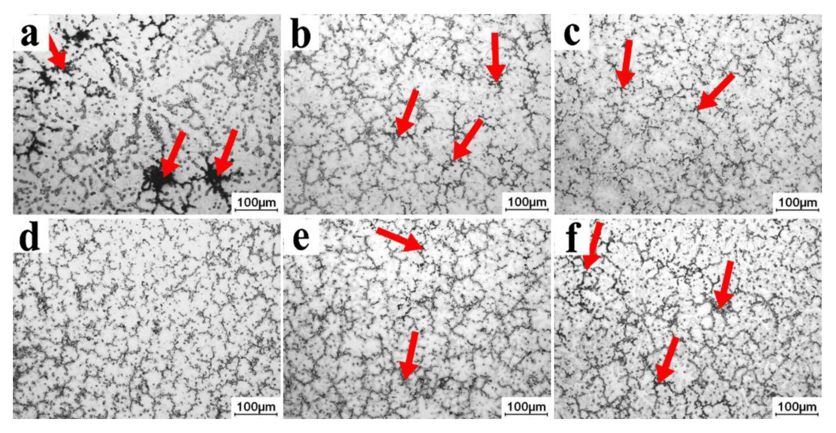
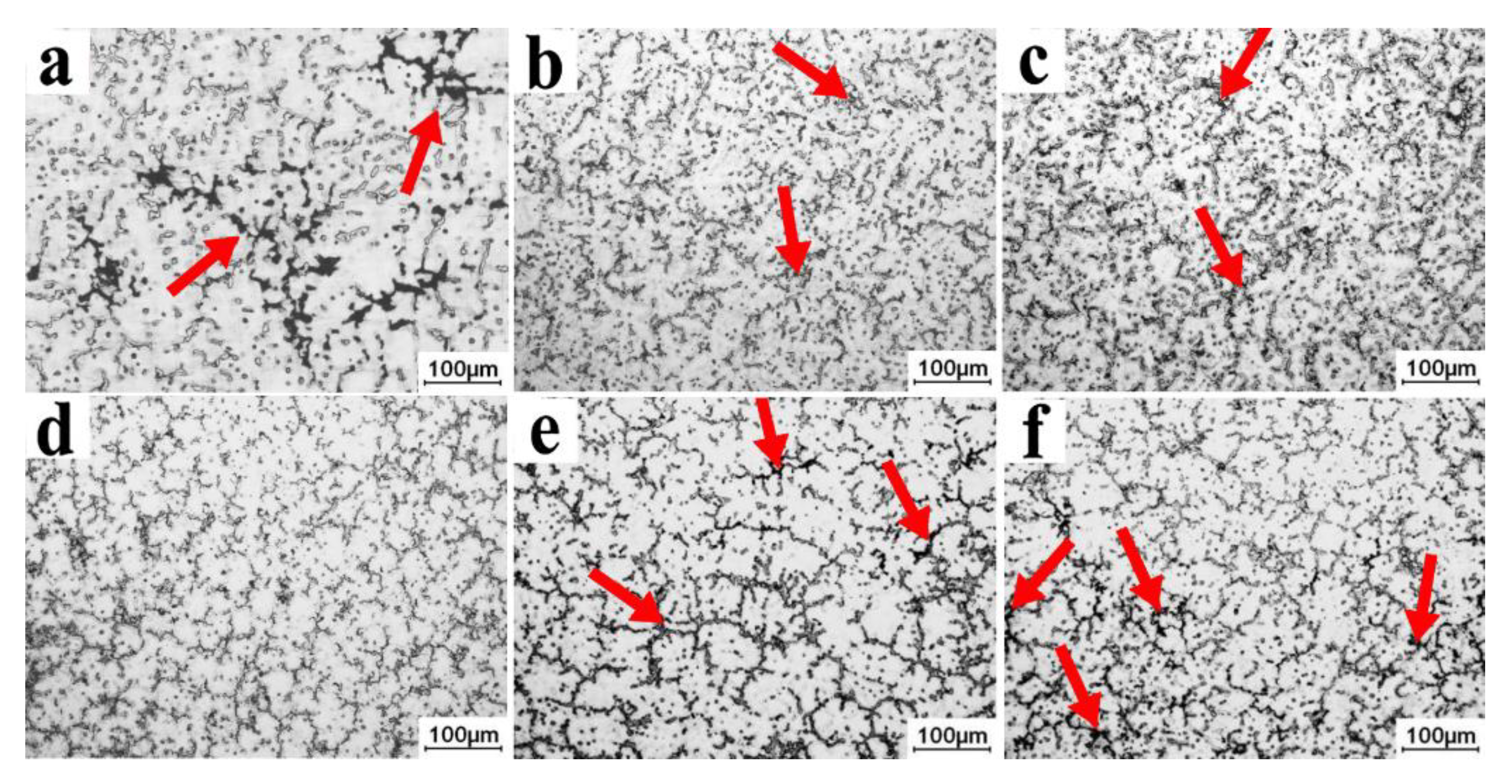
3.1. Effect of Grp Content on the Microstructure
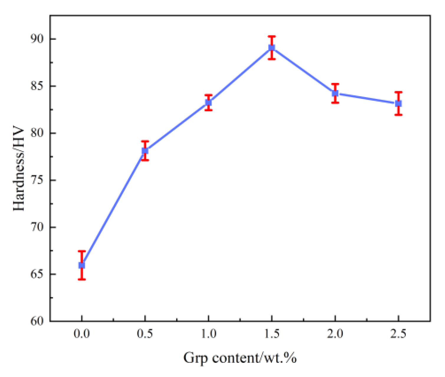
3.2. Effect of Grp Content on Hardness Properties
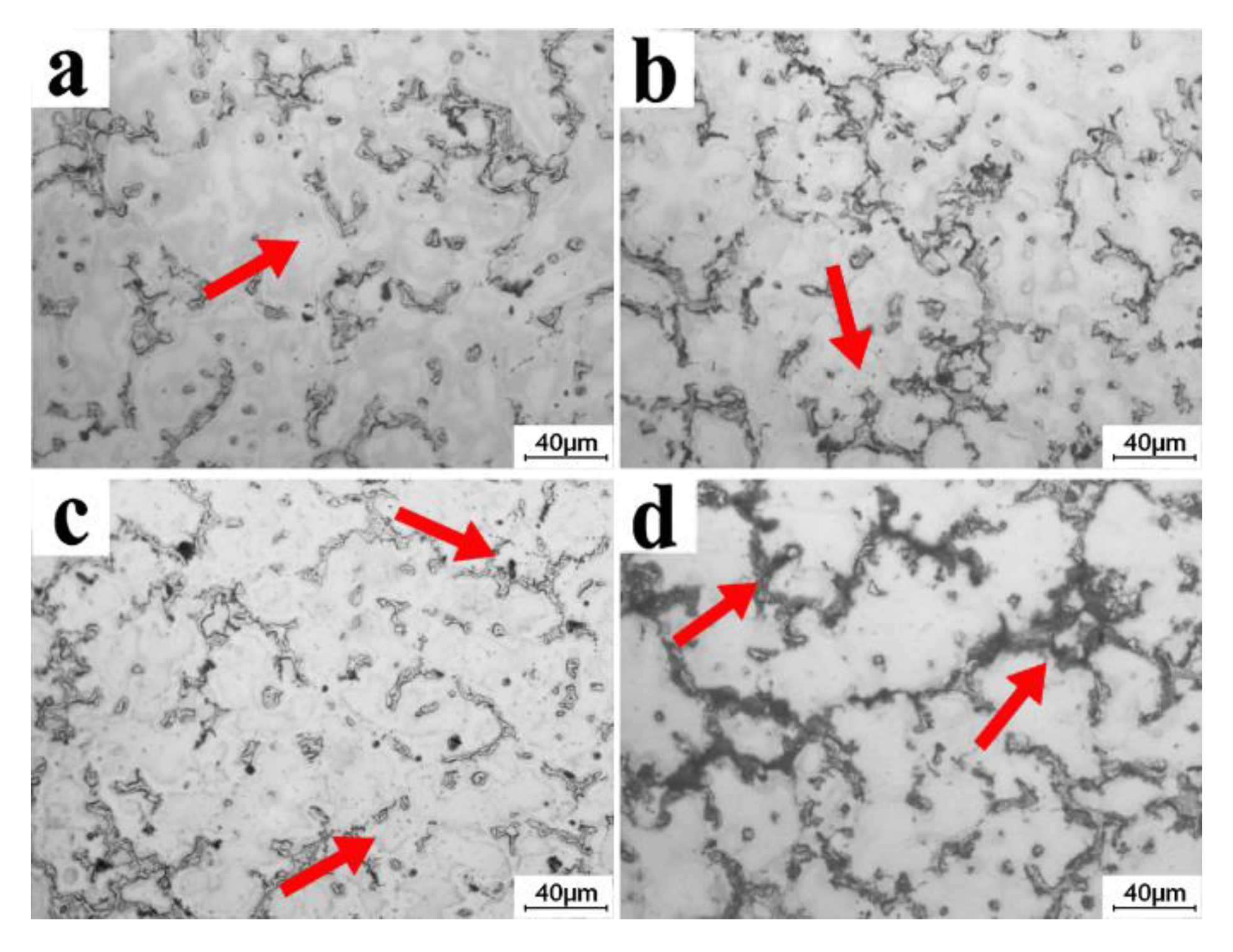
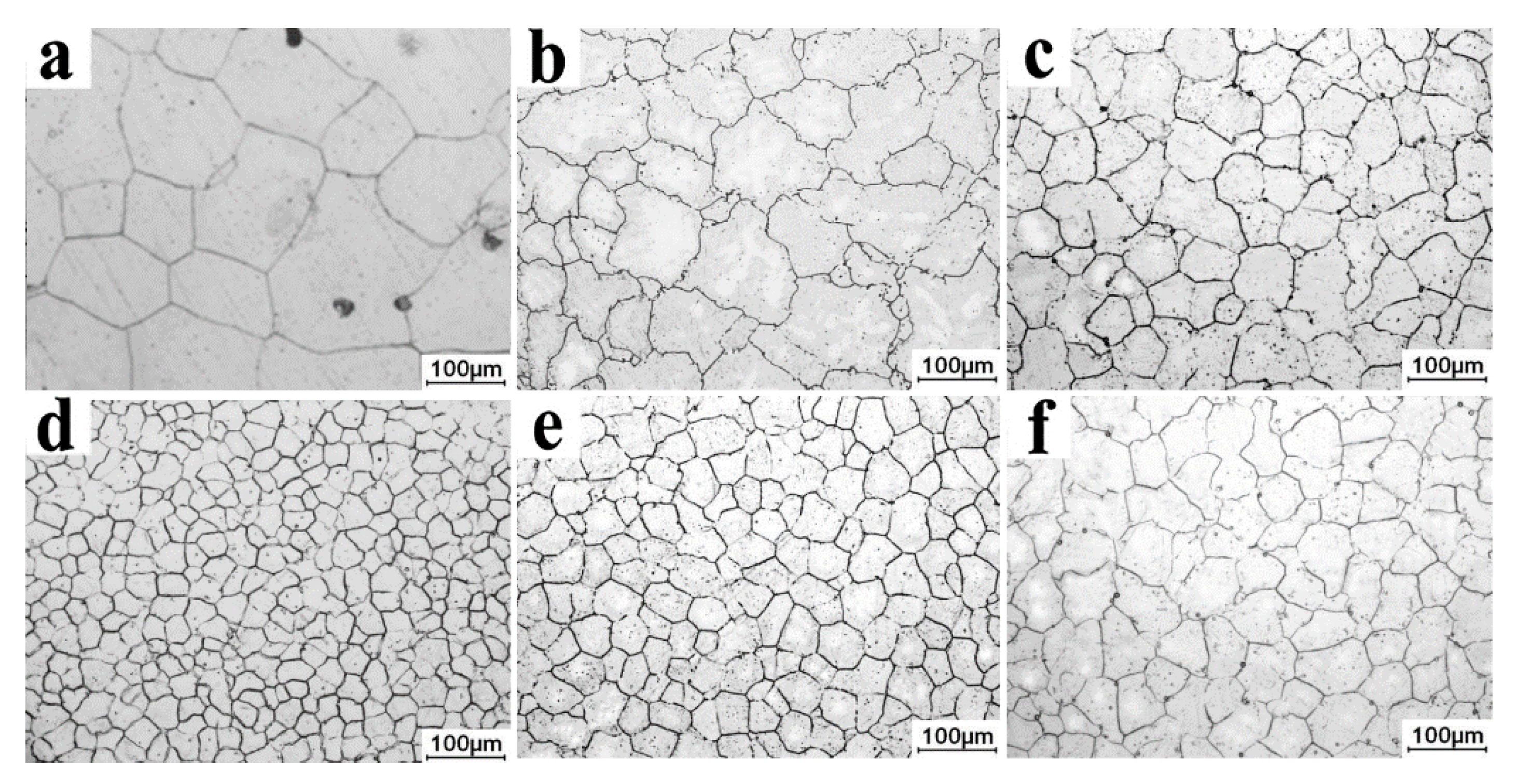
3.3. Effect of Holding Time on Microstructure
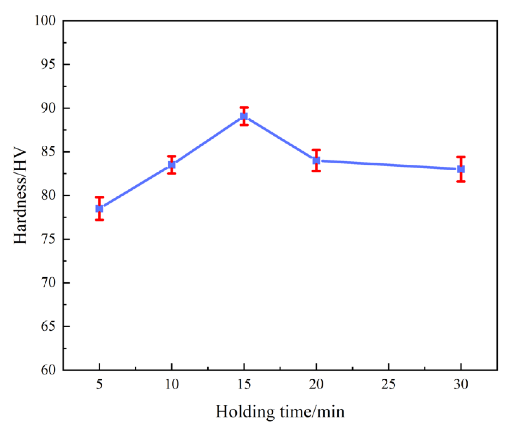
3.4. Effect of Holding Time on the Hardness Properties
4. Discussion
4.1. Grain Refinement of Grp
4.2. Self-Stablizing Effect
4.3. The Relationships between the Solidifying Interface and the Particle
5. Conclusions and Outlooks
Author Contributions
Funding
Data Availability Statement
Acknowledgments
Conflicts of Interest
References
- Zhang, S.; Chen, T.; Cheng, F.; Li, P. A comparative characterization of the microstructures and tensile properties of as-cast and thixoforged in situ AM60B-10 vol% Mg2Sip composite and thixoforged AM60B. Metals 2015, 5, 457–470. [Google Scholar] [CrossRef]
- Chen, L.Y.; Xu, J.Q.; Choi, H.; Pozuelo, M.; Ma, X.; Bhowmick, S.; Yang, J.; Mathaudhu, S.; Li, X. Processing and properties of magnesium containing a dense uniform dispersion of nanoparticles. Nature 2015, 528, 539–543. [Google Scholar] [CrossRef] [PubMed]
- Chen, X.; Geng, Y.; Pan, F. Research progress in magnesium alloys as functional materials. Rare Met. Mater. Eng. 2016, 45, 2269–2274. [Google Scholar]
- Chen, T.; Huang, L.; Huang, X.; Ma, Y.; Hao, Y. Effects of mould temperature and grain refiner amount on microstructure and tensile properties of thixoforged AZ63 magnesium alloy. J. Alloy. Compd. 2013, 556, 167–177. [Google Scholar] [CrossRef]
- Li, J.; Jiang, Q.; Sun, H.; Li, Y. Effect of heat treatment on corrosion behavior of AZ63 magnesium alloy in 3.5 wt.% sodium chloride solution. Corros. Sci. 2016, 111, 288–301. [Google Scholar] [CrossRef] [Green Version]
- Bettles, C.J. Magnesium powder metallurgy: Process and materials opportunities. J. Mater. Eng. Perform. 2008, 17, 297–301. [Google Scholar] [CrossRef]
- Hao, Y.; Chen, T.; Ma, Y.; Li, Y.; Yan, F.; Huang, X. Some key issues and accesses to the application of magnesium alloys. Int. J. Mod. Phys. B 2010, 24, 2237–2242. [Google Scholar] [CrossRef]
- Gupta, M.; Lai, M.O.; Saravanaranganathan, D. Synthesis, microstructure and properties characterization of disintegrated melt deposited Mg/SiC composites. J. Mater. Sci. 2000, 35, 2155–2165. [Google Scholar] [CrossRef]
- Contreras, A.; Lopez, V.H.; Bedolla, E. Mg/TiC composites manufactured by pressureless melt infiltration. Scr. Mater. 2004, 51, 249–253. [Google Scholar] [CrossRef]
- Habibnejad-Korayem, M.; Mahmudi, R.; Poole, W.J. Enhanced properties of Mg-based nano-composites reinforced with Al2O3 nano-particles. Mater. Sci. Eng. A 2009, 519, 198–203. [Google Scholar] [CrossRef]
- Lei, P.; Gang, C.; Zhao, Y.; Huang, K.; Shao, Y. Influence of solution treatment on microstructure and properties of in-situ Mg2Si/AZ91D composites. Trans. Nonferrous Met. Soc. China 2011, 21, 2365–2371. [Google Scholar]
- Deng, K.; Wang, C.; Nie, K.; Wang, X. Recent research on the deformation behavior of particle reinforced magnesium matrix composite: A review. Acta Metall. Sin. (Engl. Lett.) 2019, 32, 413–425. [Google Scholar] [CrossRef]
- Rashad, M.; Pan, F.; Tang, A.; Muhammad, A.; Muhamad, A. Synergetic effect of graphene nanoplatelets (GNPs) and multi-walled carbon nanotube (MW-CNTs) on mechanical properties of pure magnesium. J. Alloy. Compd. 2014, 603, 111–118. [Google Scholar] [CrossRef]
- Liang, J.; Li, H.; Qi, L.; Tian, W.; Chao, X.; Wei, J. Fabrication and mechanical properties of CNTs/Mg composites prepared by combining friction stir processing and ultrasonic assisted extrusion. J. Alloy. Compd. 2017, 728, 282–288. [Google Scholar] [CrossRef]
- Chen, X.; Li, Q.; Chen, J.; Zhu, L. Microstructure and mechanical properties of Mg-Gd-Y-Sm-Al alloy and analysis of grain refinement and strengthening mechanism. J. Rare Earths 2019, 37, 1351–1358. [Google Scholar] [CrossRef]
- Wang, C.; Deng, K.; Bai, Y. Microstructure, and mechanical and Wear properties of Grp/AZ91 magnesium matrix composites. Materials 2019, 12, 1190. [Google Scholar] [CrossRef] [Green Version]
- Wu, Y.; Wu, K.; Deng, K.; Nie, X.; Wang, X.; Hu, X.; Zheng, M. Effect of extrusion temperature on microstructures and damping capacities of Grp/AZ91 composite. J. Alloy. Compd. 2010, 506, 688–692. [Google Scholar] [CrossRef]
- Li, C.; Yang, S.; Luo, G.; Liao, H.; Du, J. Revealing the nuclei formation in carbon-inoculated Mg-3% Al alloys containing trace Fe. Materials 2019, 12, 2478. [Google Scholar] [CrossRef] [Green Version]
- Chen, H.L.; Schmid-Fetzer, R. The Mg–C phase equilibria and their thermodynamic basis. Int. J. Mater. Res. 2012, 103, 1294–1301. [Google Scholar] [CrossRef]
- Coltters, R.G. Thermodynamics of binary metallic carbides: A review. Mater. Sci. Eng. 1985, 76, 1–50. [Google Scholar] [CrossRef]
- Li, K.; Sun, Z.G.; Wang, F.; Zhou, N.; Hu, X. First-principles calculations on Mg/Al4C3 interfaces. Appl. Surf. Sci. 2013, 270, 584–589. [Google Scholar] [CrossRef]
- Viala, J.C.; Claveyrolas, G.; Bosselet, F.; Bouix, J. The chemical behaviour of carbon fibres in magnesium base Mg-Al alloys. J. Mater. Sci. 2000, 35, 1813–1825. [Google Scholar] [CrossRef]
- Viala, J.C.; Fortier, P.; Claveyrolas, G.; Vincent, H.; Bouix, J. Effect of magnesium on the composition, microstructure and mechanical properties of carbon fibres. J. Mater. Sci. 1991, 26, 4977–4984. [Google Scholar] [CrossRef]
- Lu, L.; Dahle, A.K.; StJohn, D.H. Grain refinement efficiency and mechanism of aluminum carbide in Mg–Al alloys. Scr. Mater. 2005, 53, 517–522. [Google Scholar] [CrossRef]
- Presel, F.; Gijon, A.; Hernandez, E.R.; Lacoving, P.; Lizzit, S.; Alfe, D.; Baraldi, A. Translucency of Graphene to van der Waals Forces Applies to Atoms/Molecules with Different Polar Character. ACS Nano 2019, 13, 12230–12241. [Google Scholar] [CrossRef] [PubMed]
- Zhang, A.; Zhao, Z.; Yin, G.; Lin, C. A novel model to account for the heterogeneous nucleation mechanism of α-Mg refined with Al4C3 in Mg-Al alloy. Comput. Mater. Sci. 2017, 140, 61–69. [Google Scholar] [CrossRef]
- Shangguan, D.; Ahuja, S.; Stefanescu, D.M. An analytical model for the interaction between an insoluble particle and an advancing solid/liquid interface. Metall. Trans. A 1992, 23, 669–680. [Google Scholar] [CrossRef]


| Remelting Temperature (°C) | Grp Content (wt.%) | Holding Time (min) | Pouring Temperature (°C) | Protective Gas | Type of Cooling |
|---|---|---|---|---|---|
| 780 | 0.5 | 15 | 740 | SF6 + CO2 | Air cooling |
| 1.0 | |||||
| 1.5 | |||||
| 2.0 | |||||
| 2.5 |
| Remelting Temperature (°C) | Grp Content (wt.%) | Holding Time (min) | Pouring Temperature (°C) | Protective Gas | Type of Cooling |
|---|---|---|---|---|---|
| 780 | 1.5 | 0 | 740 | SF6 + CO2 | Air cooling |
| 5 | |||||
| 10 | |||||
| 15 | |||||
| 20 |
| Position | Molar Fraction/% | |||
|---|---|---|---|---|
| Mg | Al | Zn | C | |
| A | 78.39 | 13.04 | 0.63 | 7.94 |
| B | 55.98 | 36.23 | 1.97 | 5.82 |
| C | 43.13 | 30.24 | 0.25 | 26.38 |
Disclaimer/Publisher’s Note: The statements, opinions and data contained in all publications are solely those of the individual author(s) and contributor(s) and not of MDPI and/or the editor(s). MDPI and/or the editor(s) disclaim responsibility for any injury to people or property resulting from any ideas, methods, instructions or products referred to in the content. |
© 2022 by the authors. Licensee MDPI, Basel, Switzerland. This article is an open access article distributed under the terms and conditions of the Creative Commons Attribution (CC BY) license (https://creativecommons.org/licenses/by/4.0/).
Share and Cite
Gao, X.; Geng, K.; Sun, C.; Zhang, S.; Zhou, J.; Wu, J.; Zhang, X.; Wang, X. Effects of Graphite Particle Content and Holding Time on the Microstructure and Mechanical Properties of the Graphite/AZ91D Composite. Metals 2023, 13, 57. https://doi.org/10.3390/met13010057
Gao X, Geng K, Sun C, Zhang S, Zhou J, Wu J, Zhang X, Wang X. Effects of Graphite Particle Content and Holding Time on the Microstructure and Mechanical Properties of the Graphite/AZ91D Composite. Metals. 2023; 13(1):57. https://doi.org/10.3390/met13010057
Chicago/Turabian StyleGao, Xin, Kejian Geng, Cuicui Sun, Suqing Zhang, Jixue Zhou, Jianhua Wu, Xinfang Zhang, and Xitao Wang. 2023. "Effects of Graphite Particle Content and Holding Time on the Microstructure and Mechanical Properties of the Graphite/AZ91D Composite" Metals 13, no. 1: 57. https://doi.org/10.3390/met13010057