Article

Microstructure Evolution in a GOES Thin Strip

by
Anastasia Volodarskaja
1,
Kryštof Hradečný
1,2,
Renáta Palupčíková
1,2,
Petra Váňová
1 and
Vlastimil Vodárek
1,2,*
1
Faculty of Materials Science and Technology, VŠB—Technical University of Ostrava, 17. listopadu 2172/15, 708 00 Ostrava, Czech Republic
2
Centre for Advanced Innovation Technologies, VŠB—Technical University of Ostrava, 17. listopadu 2172/15, 708 00 Ostrava, Czech Republic
*
Author to whom correspondence should be addressed.
Metals 2023, 13(1), 51; https://doi.org/10.3390/met13010051
Submission received: 24 November 2022 / Revised: 17 December 2022 / Accepted: 20 December 2022 / Published: 24 December 2022
(This article belongs to the Special Issue Texture, Microstructure and Properties of Electrical Steels)

Abstract

:
This paper focuses on the evolution of the microstructure in a grain-oriented electrical steel (GOES) thin strip after casting. After solidification, the microstructure consisted of delta-ferrite. A small fraction of austenite was formed during the cooling of the thin strip in the two-phase region (gamma+delta). Fine Cr2CuS4 particles precipitated in the ferrite and along the delta/gamma interfaces. Laths of primary Widmanstätten austenite (WA) nucleated directly on the high-angle delta-ferrite grain boundaries. The formation of WA laths in both adjacent ferritic grains resulted in a zig-zag shape of delta-ferrite grain boundaries due to their local rotation during austenite nucleation. Based on the EBSD results, a mechanism of the formation of the zig-zag grain boundaries has been proposed. Besides the Widmanstätten morphology, austenite also formed as films along the delta-ferrite grain boundaries. Sulfide precipitation along the delta/gamma interfaces made it possible to prove that austenite decomposition upon a drop in temperature was initiated by the formation of epitaxial ferrite. Further cooling brought the decay of austenite to either pearlite or a mixture of plate martensite and some retained austenite.

1. Introduction

Thin strip casting on a moving belt is a modern, innovative method for producing flat metallurgical intermediate products that is cost-efficient and has low ecological impact [1,2]. This technological process makes it possible to minimize the costs associated with subsequent processes that are used to reduce the thickness of intermediate products in order to attain the final required thickness of products. Recent progress in the optimization of this technology has enabled the production of GOES thin strips [3,4,5,6,7,8,9,10,11].
During the solidification of GOES thin strips, a microstructure consisting of δ-ferrite is created. During the cooling of the solidified thin strips, austenite is formed in a two-phase region (γ+δ), and precipitation processes occur in the ferritic matrix. The austenite created in GOES thin strips may display Widmanstätten morphology [12]. Below the two-phase region (γ+δ), austenite decomposition occurs. In general terms, the austenite decomposition mechanism is dependent on the speed of the cooling of the thin strips, the chemical composition, and the size of austenite islands. In GOES thin strips, austenite decomposition has been observed to be accompanied by the formation of pearlite or martensite [13,14].
It has been proven that WA laths are formed by a displacive mechanism, which is accompanied by carbon redistribution [12]. This austenite morphology has also been observed in duplex and maraging steels [15,16,17,18]. Between the WA and the ferritic matrix, there is an orientation relationship approaching the Kurdjumov–Sachs (K-S) OR: (111)γ//(011)δ and [−101]γ//[−1−11]δ [12,18]. Ameyama et al. [17], studying 25Cr-6Ni duplex steel (mass %), observed that the nucleation of WA occurs on continuous austenite films or on allotriomorphic austenite particles precipitated along ferritic grain boundaries (secondary WA). Studying WA in GOES, Song et al. [12] observed that the main nucleation sites of austenite were located directly at the δ-ferrite grain boundaries, whereas the occurrence of allotriomorphic austenite particles or austenite films along the δ-ferrite grain boundaries was not proven. The results of a study of WA morphology in GOES show that it consists primarily of laths [12]. The analysis of the direction of WA growth in the ferritic matrix found that austenite laths grow along an invariant line <011>γ//<111>α [18]. Parallel WA laths often have approximately the same distances between individual formations; this is believed to be associated with the important role played by diffusion processes in their growth [16]. The results of wave-dispersive X-ray (WDX) microanalysis in [12] indicate that the formation of WA laths in GOES is accompanied not only by carbon redistribution, but also probably by silicon redistribution.
The aim of this paper is to contribute to a deeper understanding of the evolution of the microstructure in GOES thin strips cast on a moving belt. Particular attention is paid to the formation of WA laths, the precipitation of minor phases in δ-ferrite, and austenite decomposition mechanisms.

2. Experiment

The GOES thin strip that was the subject of this study was produced at the Clausthal University of Technology using horizontal casting technology [19]. In this case, molten steel is directed from an intermediate ladle onto a moving water-cooled belt, creating a thin strip (thickness up to 20 mm). In the experiment described here, the strip was 14 mm thick and 300 mm wide. The upper surface of the thin strip was protected by an argon atmosphere during solidification and subsequent cooling. The cooling speed varied through the thickness of the strip. The mean cooling speed on the upper surface of the strip (in the temperature interval 1573–973 K) was approximately 2 Ks−1. The chemical composition of the studied GOES thin strip is stated in Table 1. It corresponds to a GOES variant with increased sulfur content; sulfide particles are utilized as the inhibition phase before the initiation of the secondary recrystallization process, leading to the formation of Goss texture {110}<001> [3,20].
The microstructural parameters were evaluated from longitudinal sections across the entire thickness of the strip; samples were taken from the central part of the strip width. Microstructural characterization was carried out using light microscopy (LM), scanning electron microscopy (SEM), transmission electron microscopy (TEM), and X-ray diffractometry (XRD). XRD measurements were carried out using a Bruker AXS D8 Advance diffractometer equipped with a position sensitive detector LynxEye. The following parameters were applied: radiation CuKα, absorption filter Ni, voltage 40 kV, current 40 mA, step 0.014° in the interval of 2θ angles 40–135°, and digital processing of data using the Bruker Diffract Suite software. The diffraction database PDF-2 was applied for qualitative analysis, and quantification was based on the Rietveld’s method using the software Bruker Topas, version 4.2.
The microstructure of the metallographic samples was revealed by etching in a 2% Nital solution and observing in an Olympus GX51 microscope. The Image-Pro software was used for image analysis. SEM investigations were performed using a Quanta 450FEG microscope equipped with X-ray microanalysis (EDX) and electron backscattered diffraction (EBSD) facilities. EBSD mapping was carried out at an accelerating voltage of 15 kV and a step size of 0.1 μm was applied. The samples for the EBSD analysis were prepared by mechanical grinding and polishing with diamond paste; final polishing was then carried out with colloidal silica (grain size 50 nm). OIM AnalysisTM software was used for the acquisition, Kikuchi diffractogram indexing, and subsequent processing of the EBSD data. Minor phases were studied using a JEM 2100 transmission electron microscope equipped with an X-ray microanalysis (EDX) facility. Investigations were carried out on extraction carbon replicas. An etched metallographic sample was coated with a carbon layer with a thickness of 12 nm. Electrolytic etching in a 7% HNO3 solution in alcohol was applied to release the carbon film from the substrate. The carbon film with minor phase particles was stripped to the water surface and, after a thorough rinse in water, pieces of the carbon film were fished out on the backing grid. The identification of minor phases was performed using a combination of selected area electron diffraction (SAED) and energy-dispersive X-ray microanalysis.

3. Results

3.1. Microstructural Characteristics of the GOES Thin Strip

The inverse pole figure (IPF) orientation map in Figure 1a documents the microstructure through the thickness of the studied strip. The microstructure consists primarily of coarse-grained δ-ferrite and needle-shaped products of austenite decomposition. The austenite in the microstructure was produced during the cooling of the thin strip in the two-phase region (γ+δ), and its decomposition occurred upon a drop in temperature below this two-phase region. Products of austenite decomposition, as determined by image analysis, made up approximately 2% of the total area. The uneven heat extraction across the thickness of the thin strip caused a decrease in the ferritic grain size immediately under the bottom surface of the strip, and also in the region of the final solidification, located approximately ¼ of the way through the thickness of the strip from the top surface. The image quality map is shown in Figure 1b, on which the high-angle and low-angle δ-ferrite grain boundaries are highlighted.
Using light microscopy, the occurrence of numerous subgrains inside the δ-ferrite grains was observed. The EBSD results showed that the mutual disorientation of subgrains is mainly less than 2°. A section of the Fe-Si phase diagram shows that for Fe steel with 2.8 mass % Si, the two-phase region (γ+δ) is located in the temperature interval 1620–1050 K [12]. Using differential scanning calorimetry, when heating the thin strip at a rate of 0.25 Ks−1, thermal effects associated with the formation of austenite are observed in the temperature interval 1093–1125 K [14]. The effects observed in the temperature interval 1442–1510 K are probably connected with the dissolution of austenite and minor phases [14].
The products of austenite decomposition in the studied thin strip were identified as pearlite and martensite. Partial austenite decomposition producing plate martensite led to the retention of a small fraction of retained austenite in the final microstructure. The fraction of retained austenite determined using XRD was close to the detection limit, approximately 0.5 mass %. In view of the low carbon content in the studied GOES, it is evident that the formation of austenite in the δ-ferrite matrix was accompanied by substantial carbon redistribution. Plate martensite occurs in steels with a carbon content higher than approx. 0.6 mass % [21]. The particles created during austenite decomposition were usually needle-shaped; this proves that the original austenite had Widmanstätten morphology. The main nucleation sites of the WA laths were directly on the high-angle δ-ferrite grain boundaries (primary WA); see Figure 1b. In some cases, their formation was accompanied by the local rotation of ferrite grain boundaries. Figure 2 shows a local rotation of the high-angle ferrite grain boundary caused by the nucleation of austenite. In order to achieve the optimum variant of the orientation relationship between WA nuclei and the δ1 ferritic grain, all WA/δ1 interfaces are planar and parallel each to other. The observed rotation of δ-ferrite grain boundaries was probably facilitated by the high temperature of the austenite formation. When the austenite nuclei grew only into one δ-ferrite grain, the formation of parallel WA laths occurred and usually the straightening of δ-ferrite grain boundaries was observed; see Figure 3. Figure 4 shows a transverse section through the WA laths in which austenite decomposition has occurred, either producing plate martensite + retained austenite or transforming the austenite to pearlite.
Small austenite islands displayed high structural stability, and their decomposition did not occur during the cooling of the thin strip. The arrows within a single δ-ferrite grain in Figure 1a indicate the non-parallel needle-shaped products of austenite decomposition. It indicates that WA laths in a single ferritic grain can generally belong to several variants of the K-S OR. In this case, WA laths in the particular δ-ferrite grain nucleated on grain boundary segments with several adjacent ferritic grains; see Figure 1a. When WA laths nucleated on grain boundaries grew into both adjacent δ-ferrite grains, the grain boundaries displayed a zig-zag shape; see Figure 5. Additionally, in some cases, undulating high-angle ferrite grain boundaries were observed in the immediate vicinity of WA decomposition products (Figure 6).
The morphology of the austenite decomposition products in the ferritic matrix indicates that besides austenite with Widmanstätten morphology, continuous austenite films were also formed in the two-phase (γ+δ) region along the δ-ferrite grain boundaries (Figure 7).
The investigations on the thin strip microstructure revealed that discontinuous networks of fine precipitates occurred along the low-angle boundaries of the δ-ferrite subgrains. Fine precipitate particles also occurred inside the δ-ferrite subgrains and formed discontinuous networks in the ferrite along the WA decomposition products. Fine precipitates usually did not occur in the area between these precipitate networks and WA decomposition products. This suggests that the discontinuous networks of precipitates pinned the original γ/δ-ferrite interfaces, and that the initial stage in austenite decomposition led to the creation of epitaxial ferrite; see Figure 6, Figure 7 and Figure 8. This was accompanied by a further increase in the carbon content of the remaining austenite, which was subsequently followed by austenite decomposition to produce pearlite or plate martensite plus some retained austenite. In some cases, both of these products of austenite decomposition were present within a single WA lath.
Figure 8a shows a light microscopy image documenting the needle-shaped products of austenite decomposition. It also shows networks of precipitates that originally pinned the WA/δ interfaces; see the arrows in Figure 8a. Some parts of the original WA laths were transformed to epitaxial ferrite, as is evident from the phase map and the IPF orientation map shown in Figure 8b,c. In cases where the epitaxial ferrite grew into the originally planar γ/δ interface along the δ-ferrite grain boundaries, the high-angle grain boundaries became undulated; see Figure 6.
The original shape of austenite films along δ-ferrite grain boundaries was revealed by the discontinuous networks of fine precipitates. During the decomposition of austenite films along the δ-ferrite grain boundaries, the epitaxial ferrite was first formed, and then the remaining austenite underwent decomposition, producing continuous films of decomposition products along the ferritic grain boundaries. Figure 7 shows a pearlite band, which formed during the decomposition of the austenite film along the δ-ferrite grain boundary.

3.2. Identification of Minor Phases

Figure 9a shows a typical precipitation in δ-ferrite. A TEM study of precipitates in the ferritic matrix using X-ray microanalysis found that these were sulfide particles with varying chemical compositions; see Table 2. Diffraction analysis of fine sulfides showed that they were the face-centered cubic phase Cr2CuS4 with the lattice parameter a = 0.961 nm [22]. The chemical composition of fine sulfides corresponds well with the stoichiometric composition of the Cr2CuS4 phase.
The typical morphology of fine sulfides is shown in Figure 9b. The distribution of the fine sulfide particles in the δ-ferrite indicates that these particles formed in the two-phase region (γ+δ). Sulfide precipitation was observed only in δ-ferrite and along the δ/γ interfaces.
The absence of sulfide particles in the incipient austenite is due to the higher solubility of sulfur in austenite compared with ferrite. Due to kinetic factors, sulfide precipitation did not usually occur in the epitaxial ferrite formed at the beginning of austenite decomposition. EDX analysis of the coarse sulfide particles (which occurred primarily in the region of the final solidification) has revealed a substantially different chemical composition; these sulfide particles contained up to 50 mass % Fe [14].
Besides globular sulfide particles, the ferrite also contained a small quantity of needle-shaped precipitates; see Figure 9a. These particles were identified as cementite. The precipitation of cementite particles occurred as a consequence of the decreased solubility of carbon in δ-ferrite with decreasing temperature. The number density of needle-shaped precipitate particles occurring in the ferritic matrix was very heterogeneous. These particles were usually not present in the close vicinity of the decomposed WA laths.

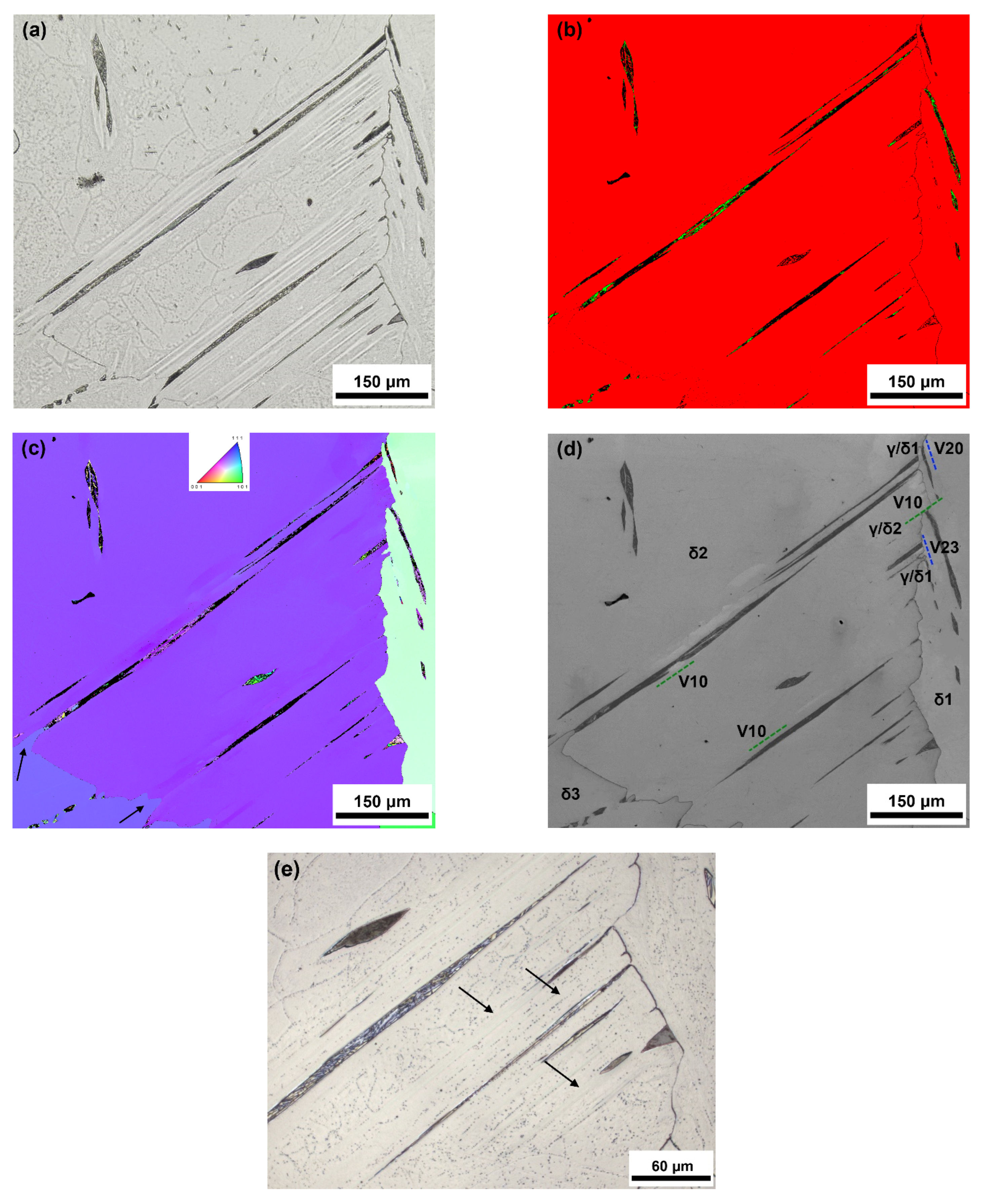
3.3. Crystallography of WA Lath Formation

Assuming an orientation relationship between δ-ferrite and WA approaching the K-S OR [12,18], 24 different orientation variants of WA may theoretically occur within one δ-ferritic grain. All variants of the OR are depicted in a combined stereographic projection (001)γ + <001>δ, shown in Figure 10. The K-S OR variants can be divided into four groups (G1–G4), with each group consisting of six OR variants with identical parallel planes {111}γ and (011)δ [23,24]. The six OR variants making up each G group are represented by the same symbols in Figure 10.
The approximately parallel austenite decomposition products shown in Figure 8a indicate that only one variant of the austenite–ferrite OR was present in a single δ-ferrite grain. The WA laths transformed to pearlite or plate martensite plus retained austenite. The phase map in Figure 8b shows the distribution of retained austenite in the WA decomposition products. The results of the analysis of the OR between the retained austenite and the ferritic grains δ1 and δ2 are shown in Figure 8d. During the nucleation of austenite along the high-angle ferrite grain boundary, its straightening occurred, and the K-S OR variant V13 was found between the austenite and the ferritic grain δ1; see Figure 8d. The K-S OR variant V20 was found between the ferrite and WA laths growing into the grain δ2. The K-S OR variants V13 and V20 belong to the OR groups G3 and G4, respectively. In this particular case, the nucleation of incipient austenite, which led to the creation of the planar interface (−111)γ//(011)δ1 (G3 group), was not accompanied by substantial rotation of the high-angle ferritic grain boundary.
Figure 11a shows a region with the occurrence of needle-shaped WA decomposition products in two adjacent δ-ferrite grains. WA laths nucleated directly at the high-angle δ-ferrite grain boundaries, and the morphology of the austenite decomposition products indicates that each δ-ferrite grain contained parallel WA laths belonging to only one variant of the K-S OR between austenite and ferrite. The decomposition of the WA laths led to the formation of pearlite and plate martensite plus retained austenite. The phase map in Figure 11b shows the presence of retained austenite in regions where plate martensite was formed during the partial decomposition of WA. The IPF orientation maps for the normal direction (ND) and the casting direction (CD) showed that the orientation of retained austenite in ferritic grains δ1 and δ2 was identical.
The results of the EBSD study of the K-S OR variants between retained austenite γ and the ferritic grains δ1 and δ2 are shown in Figure 11d. The K-S OR variant V22 occurred during the austenite nucleation at the high-angle ferritic grain boundary between the austenite and the ferritic grain δ2; see Figure 11c. The nucleation of these austenite particles was accompanied by the rotation of the high-angle ferritic grain boundary to produce parallel planes (11−1)γ//(011)δ2 in the planar γ/δ2 interface. The K-S OR variant V14 occurred during the growth of these WA laths into the ferritic grain δ1. The nucleation of austenite, growing in the form of WA laths into the ferritic grain δ2 at the grain boundary, led to the rotation of this grain boundary to produce the K-S OR variant V14 and parallel planes (−111)γ//(011)δ1 in the planar γ/δ1 interface. In the case of the WA laths growing into the ferritic grain δ2, the K-S OR variant V22 was identified between the retained austenite and the ferritic matrix. The nucleation of austenite particles on both sides of the grain boundary between ferritic grains δ1 and δ2 led to the formation of a zig-zag grain boundary. The variant V14 belongs to K-S OR group G3, while the variant V22 belongs to the K-S OR group G4. The IQ map in Figure 11e depicts the traces of the planar γ/δ1 and γ/δ2 interfaces and the growth directions of the WA laths in grains δ1 and δ2. The trace of the γ/δ1 interface along the ferritic grain boundary is parallel to the direction of WA lath growth in the ferritic grain δ1. Similarly, the trace of the γ/δ2 interface along the ferrite grain boundary is parallel to the growth direction of the WA laths in the ferritic grain δ2. The results of the EBSD analysis indicate that during the nucleation of austenite particles at the δ-ferrite grain boundary, the local rotation of the grain boundary facilitated the occurrence of the same K-S OR variant between the austenite nucleus and one δ-ferritic grain as the K-S OR variant, which existed during the growth of the WA laths into the same δ-ferrite grain; see Figure 11e.
Figure 12a shows parallel needles of decomposed WA laths, which nucleated on the opposite grain boundary segments of the δ2 ferritic grain. The decomposition products are pearlite, plate martensite with some retained austenite, and a significant fraction of WA transformed to epitaxial ferrite (Figure 12a–c). The IPF orientation maps for the normal direction (ND) and the casting direction (CD) showed that the orientation of retained austenite (WA) in the ferritic grains δ1 and δ2 was identical. All parallel laths of WA in the δ2 ferritic grain obeyed the same variant V10 of the K-S OR (Figure 12d). The planar interfaces of these WA laths at the ferritic grain boundary were parallel to the traces of the WA growth in the grain δ1 (Figure 12d). The orientation variant of the K-S OR that existed between the austenite nuclei and the δ1 ferritic grain was determined as V20, and the orientation variant for WA laths growing in the δ1 ferritic grain was V23. Variants V20 and V23 belong to the K-S OR group G4, i.e., (11−1)γ//(011)δ (see Figure 10 and Figure 12d). These WA laths nucleated at the ferritic grain boundary and formed the K-S OR variant V10 between austenite nuclei and the δ2 ferritic grain. The arrows in Figure 12c show the growth of epitaxial ferrite with the orientation identical to the δ3 ferritic grain into WA laths during their decomposition. This resulted in an undulated shape of the ferritic grain boundary. Figure 12e represents a detail of Figure 12a. It is evident that there is no precipitation of fine sulfides in the epitaxial ferrite.
The same variant of the K-S OR for parallel WA laths, which nucleated on the opposite grain boundary segment of the δ2 ferritic grain, indicates that the stresses generated in ferrite during solidification and cooling could play an important role in the selection of orientation variants of the WA laths formed in the two-phase (γ+δ) region.

4. Discussion

During the cooling of the cast GOES thin strip, Widmanstätten austenite laths and austenite films along ferritic grain boundaries formed in the two-phase (δ+γ) region. WA laths nucleated directly on the high-angle δ-ferrite grain boundaries. Intensive precipitation of sulfide particles (Cr2CuS4) along the δ/γ interfaces made it possible to demonstrate that epitaxial ferrite is formed in the initial stage of austenite decomposition. Networks of sulfide particles along the original interfaces between WA laths and δ-ferrite are documented in Figure 6 and Figure 12e. The formation of epitaxial ferrite causes the results of image analysis conducted to determine the fractions of austenite decomposition products in the ferritic matrix to underestimate the real percentage of austenite formed in the two-phase (δ+γ) region. WA laths form via a displacive mechanism, accompanied by carbon redistribution. The formation of epitaxial ferrite facilitated the enrichment of the remaining austenite to reach a eutectoid composition, and the products of austenite decomposition were either pearlite or plate martensite with some retained austenite. The austenite decomposition products were dependent on the local cooling rate, the chemical composition, and the size of the austenite particles. Small austenite islands remained stabilized in the final microstructure.
The presence of retained austenite in regions where partial austenite decomposition to plate martensite occurred made it possible to study the crystallographic parameters of the WA formation. Parallel WA laths nucleated at the ferritic grain boundary and grew either into one ferritic grain or into both adjacent ferritic grains. In the former case, a straightening of ferrite grain boundaries was usually observed. However, when WA laths grew into both adjacent ferritic grains, a zig-zag shape of the δ-ferrite grain boundaries developed. Based on the EBSD results, a mechanism of the zig-zag grain boundaries can be proposed as follows: during the nucleation of austenite on the δ-ferrite grain boundary, the local rotation of the ferritic grain boundary facilitated the occurrence of the same K-S OR variant (or a variant belonging to the same G group of the K-S OR—Figure 10) between the austenite nucleus and one δ-ferritic grain as the K-S OR variant that existed during the growth of WA laths into the same δ-ferrite grain. It can be assumed that a local rotation of ferrite grain boundaries was facilitated by the high temperature of the austenite formation. The preferred variant of the K-S OR during WA nucleation and growth is probably determined by the stresses produced during the process of solidification and cooling of the thin strip. Figure 1a demonstrates that several sets of non-parallel WA laths can form within a single δ-ferrite grain.
WA laths have a similar morphology to the Widmanstätten ferrite (WF) formed during austenite decomposition in structural steels [25,26,27]. Among the differences between these two products is that austenite is harder than ferrite, and there is a reduction in volume when ferrite is transformed to WA. In the case of WF in steels, it has been observed that due to the low driving force of the transformation at a small degree of undercooling, there is a simultaneous and cooperative growth of a pair of WF plates (representing different crystallographic variants of the OR), whose shape deformations are mutually accommodated [28]. This leads to the elimination of the majority of the deformation energy associated with the production of WF. An EBSD study of WA in the investigated thin strip found that the crystallographic orientation within individual WA laths is identical; they exhibit just one variant of the K-S OR. The easier accommodation of shape deformation during the formation of WA may be related to the volume reduction that accompanies the transformation of ferrite to austenite.

5. Conclusions

The microstructure of the GOES-cast thin strip consisted mainly of δ-ferrite, with a small fraction of austenite decomposition products. The evolution of the microstructure in the thin strip after casting can be summarized as follows:
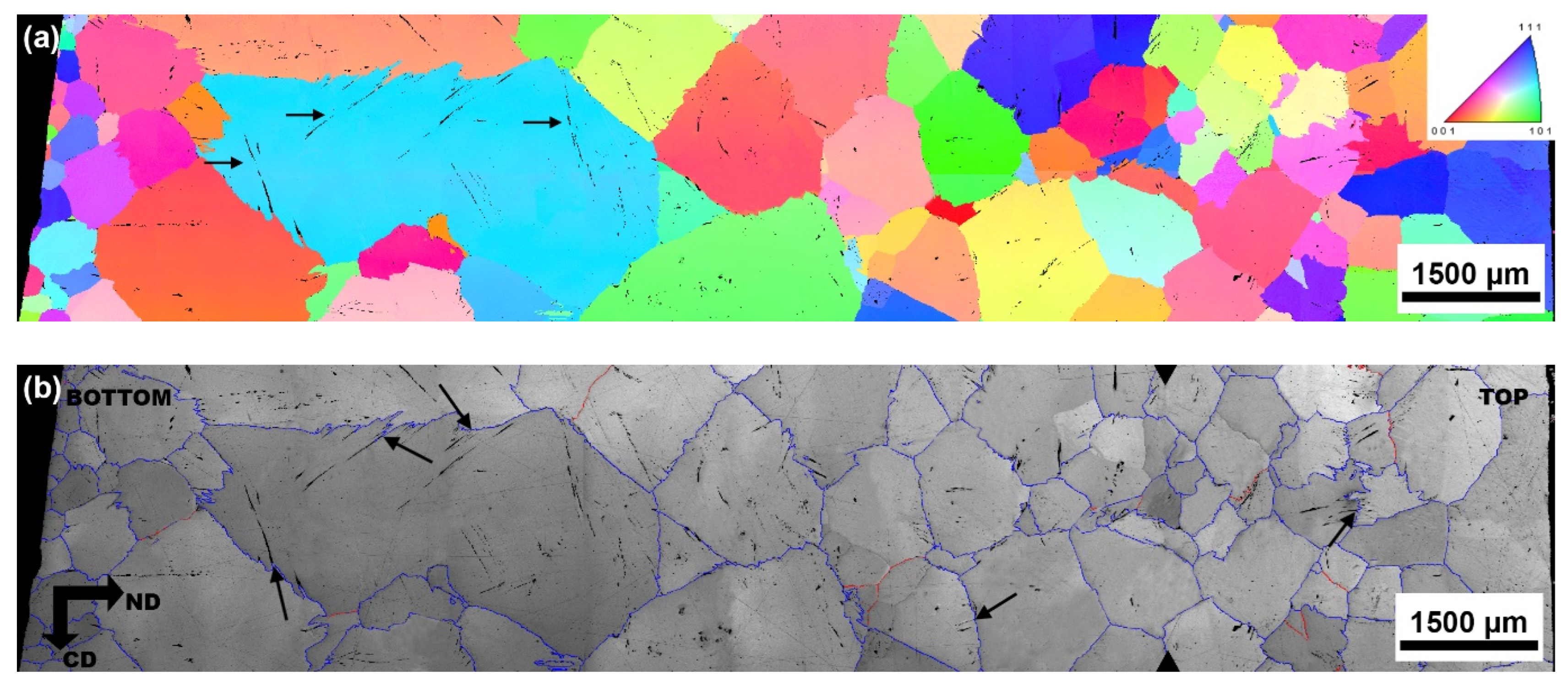
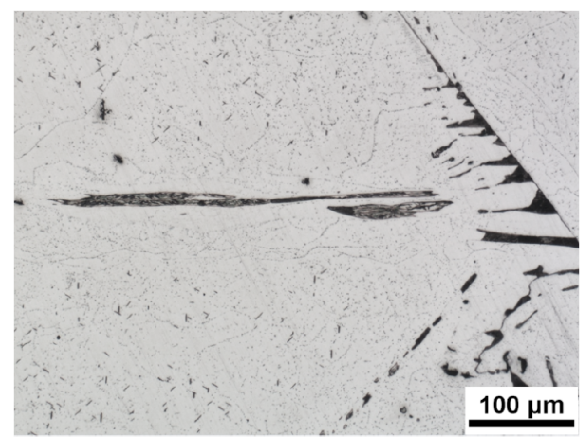
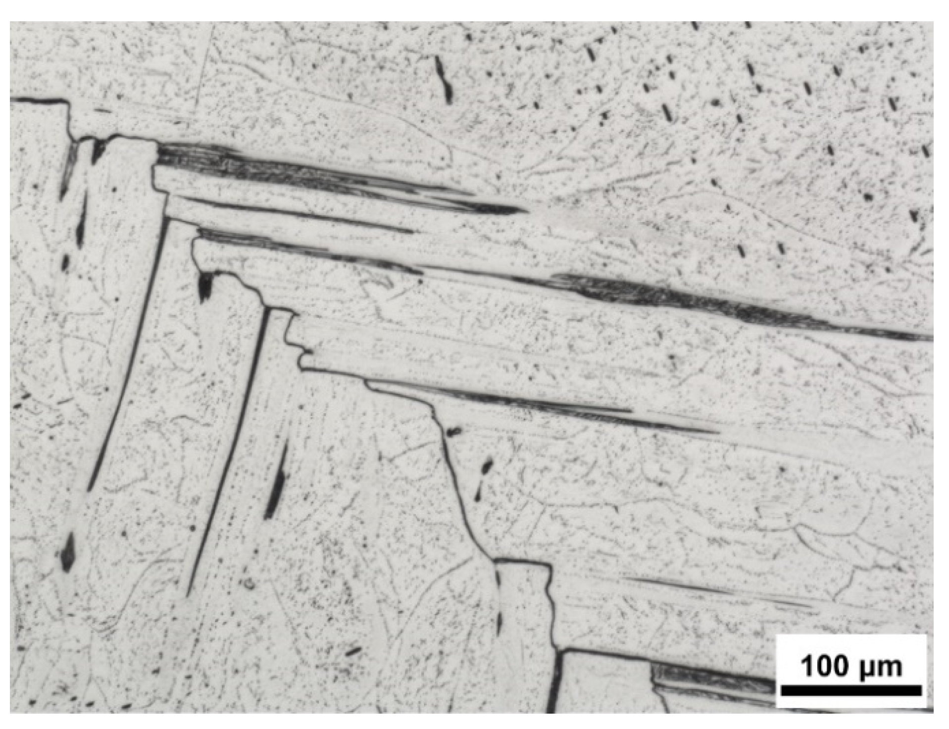
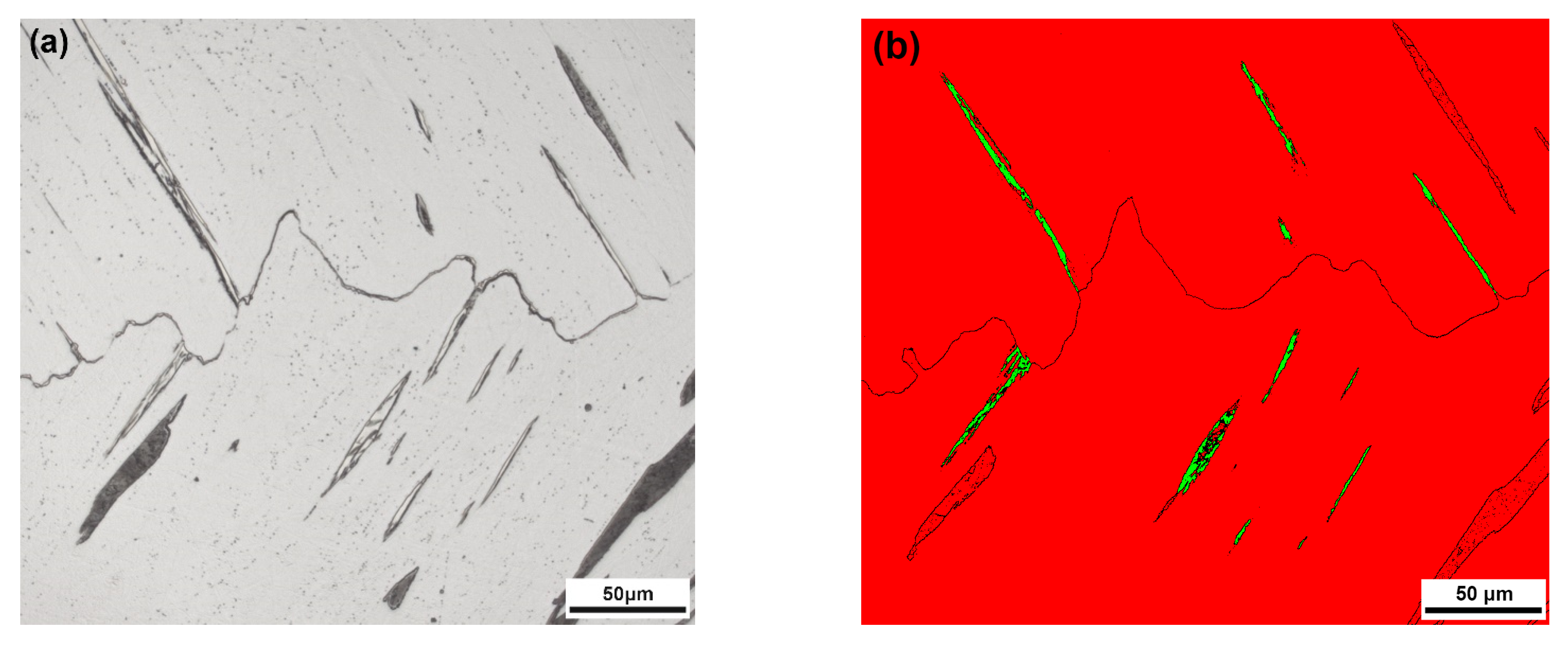
  • The microstructure consisting of δ-ferrite was formed during the solidification of the thin strip. During the cooling of the strip, austenite formed in the two-phase (γ+δ) region, primarily with Widmanstätten morphology. WA nucleated directly on the high-angle δ-ferrite grain boundaries. Additionally, austenite films were formed along some δ-ferritic grain boundaries. Upon a drop in temperature, austenite decomposition occurred, producing two morphologically different products: needle-shaped formations inside the δ-ferrite grains, and thin films along the ferrite grain boundaries.
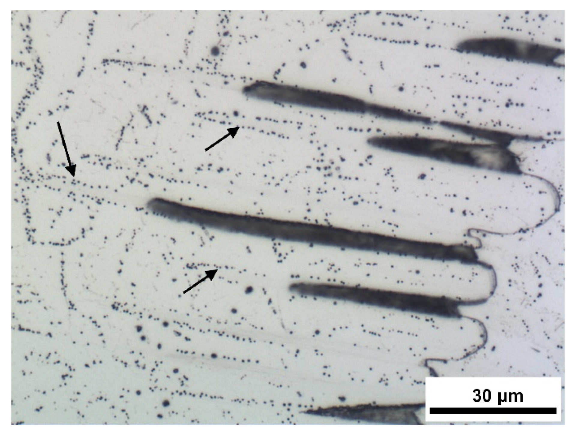
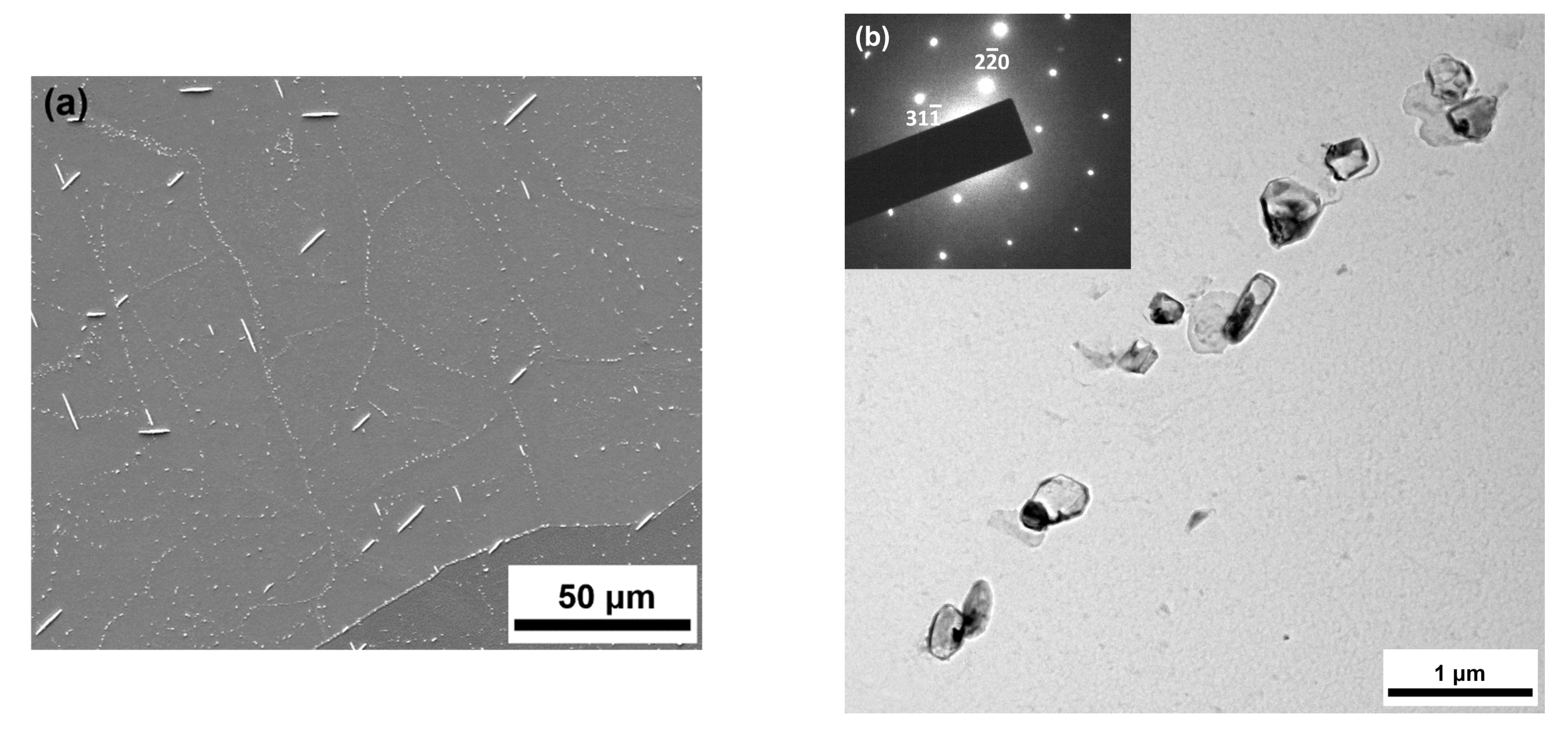
  • In the two-phase (γ+δ) region, the intensive precipitation of fine particles of complex sulfides (Cr2CuS4) occurred. Heterogeneous sulfide nucleation occurred on the ferrite grain boundaries/subgrain boundaries, but also along the δ/γ interfaces.
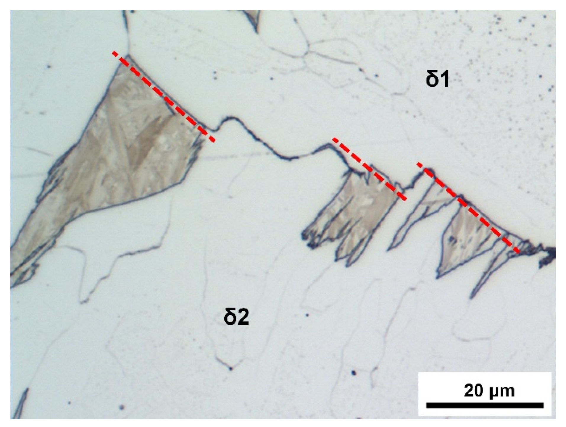
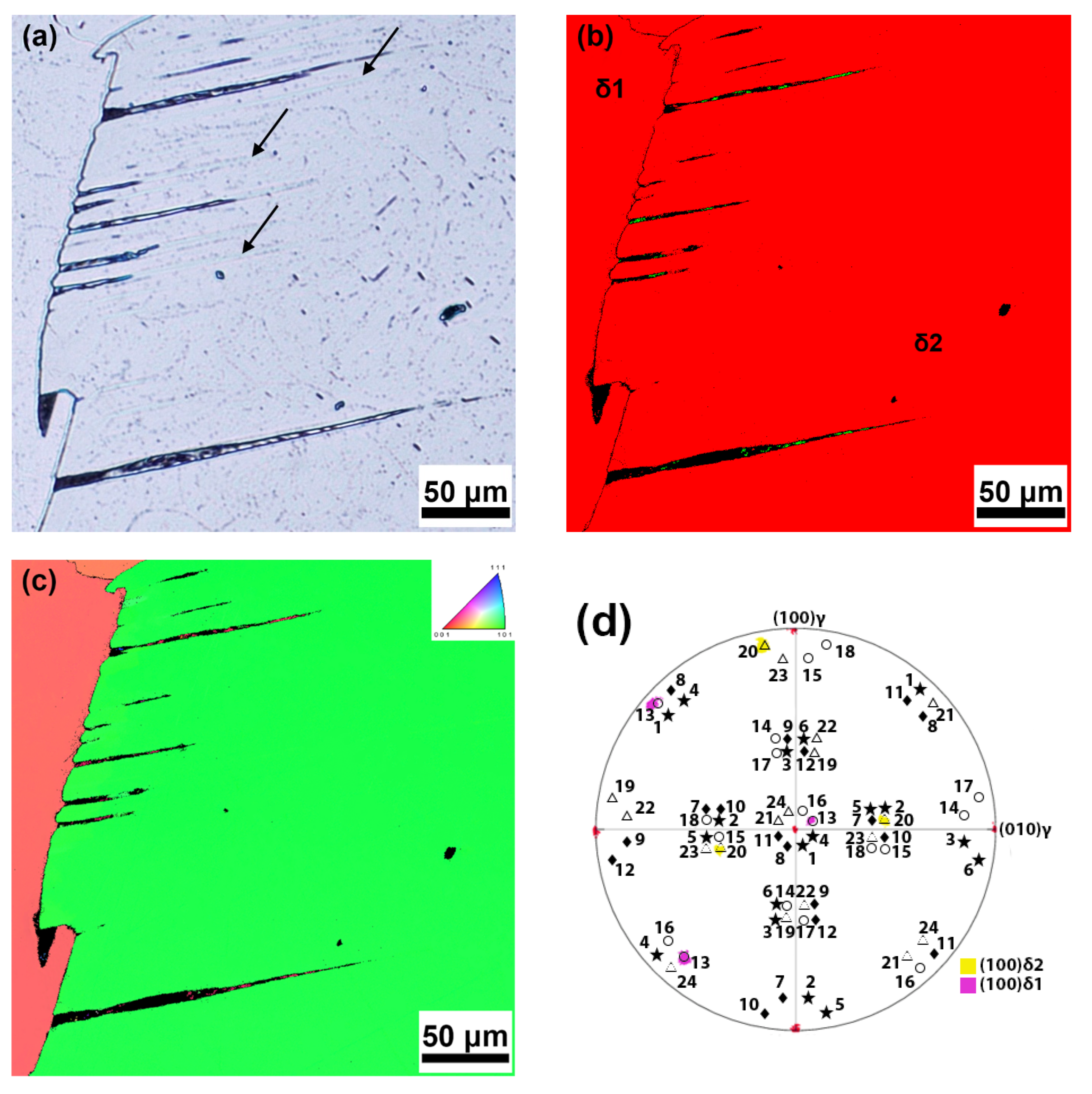
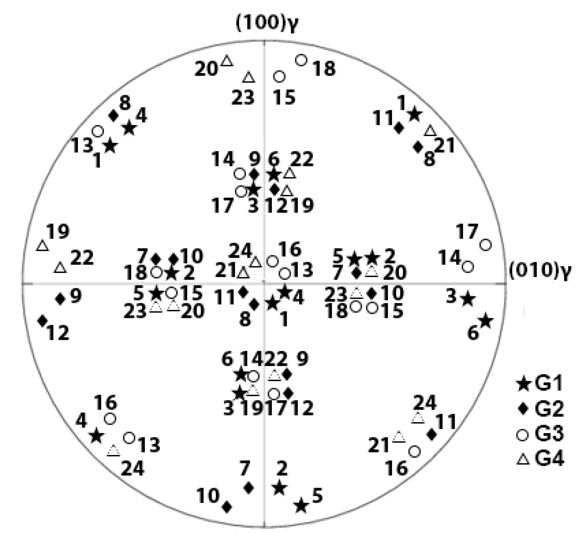
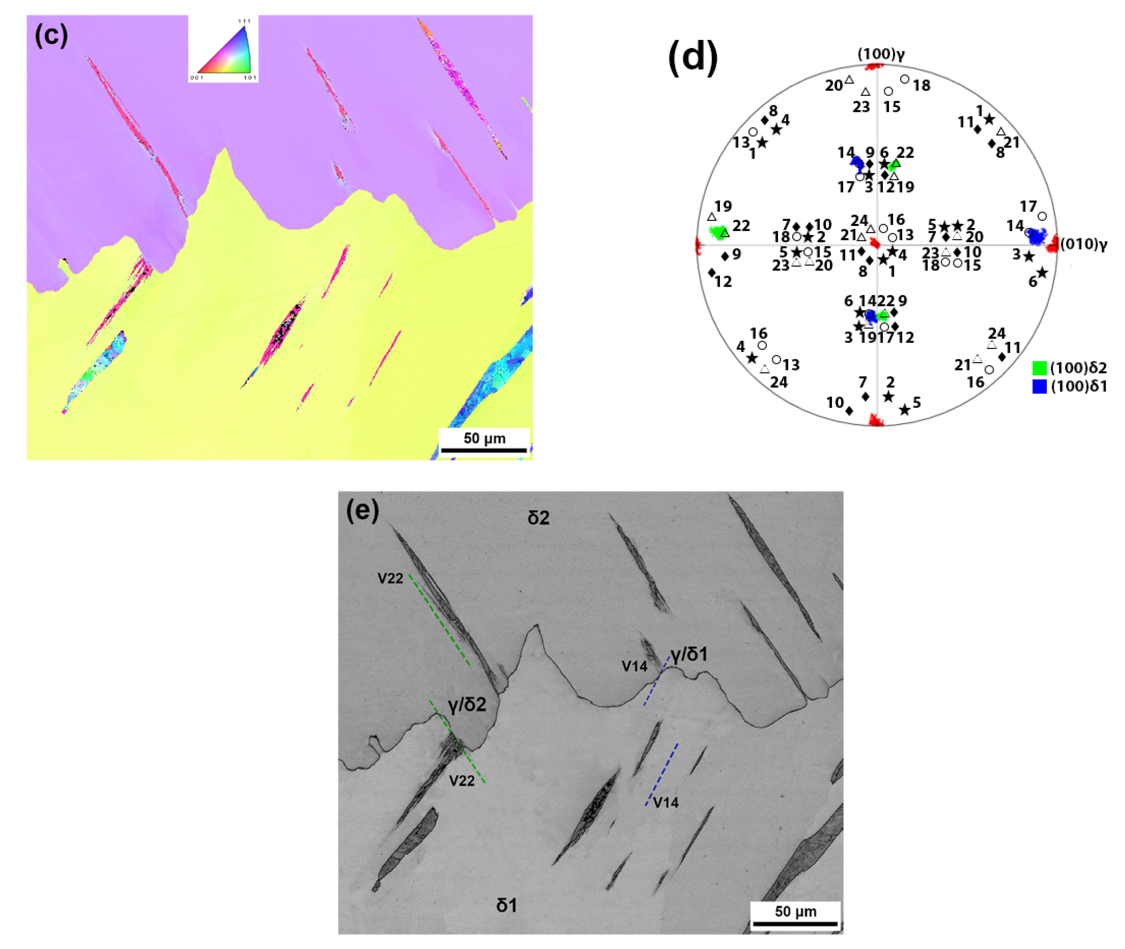
  • The WA lath growth into both adjacent δ-ferrite grains was associated with a local rotation of ferritic grain boundaries, leading to their zig-zag shape. The EBSD investigations proved that during the nucleation of austenite at the δ-ferrite grain boundary, the local rotation of the grain boundary facilitated the occurrence of the same K-S OR variant (or variant belonging to the same group G of the K-S OR) between the austenite nucleus and one δ-ferritic grain as the K-S OR variant that existed during the growth of the WA laths into the same δ-ferrite grain.
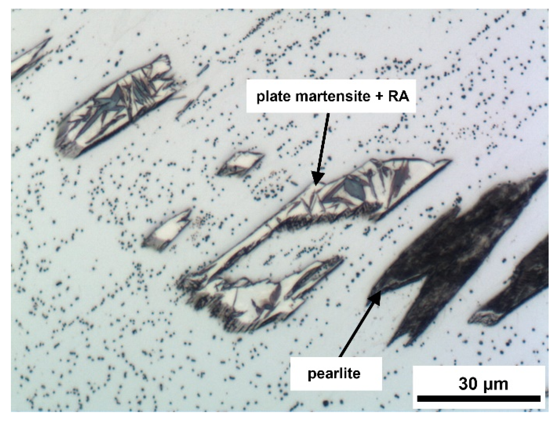
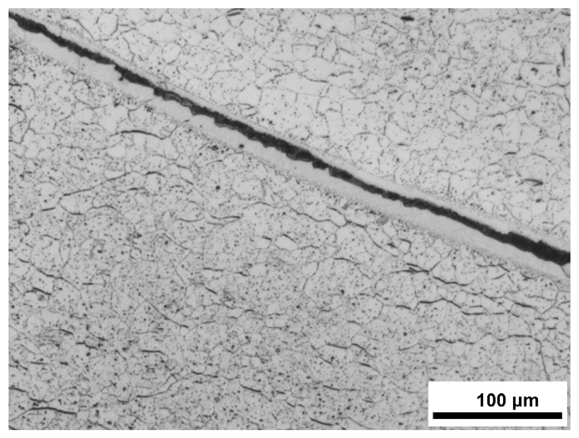
  • In the initial stage of austenite decomposition, epitaxial ferrite formed. This was accompanied by a further carbon enrichment of the remaining austenite. Austenite decomposition subsequently occurred, producing pearlite, or a mixture of plate martensite and some retained austenite.

Author Contributions

A.V.: EBSD investigations, visualization, writing—original draft; K.H.: light microscopy investigations, data curation, writing—original draft; R.P.: EBSD investigations, data curation, writing—original draft, funding acquisition; P.V.: data curation, validation; V.V.: conceptualization, TEM investigations, writing—review and editing. All authors have read and agreed to the published version of the manuscript.

Funding

This research was funded by the Czech Republic and the VŠB-Technical University of Ostrava doctoral grant, the project No. CZ.02.2.69/0.0/0.0/19_073/0016945 and by the European Union and the state budget of the Czech Republic, the project no. CZ.02.1.01/0.0/0.0/17_048/0007373.

Data Availability Statement

Not applicable.

Acknowledgments

The authors would like to thank Carl-Peter Reip, SMS group, GmbH, for providing the experimental material. This paper was an output of the Czech Republic and VŠB-Technical University of Ostrava doctoral grant (reg. no. CZ.02.2.69/0.0/0.0/19_073/0016945) within the Research, Development and Education Operational Programme, project DGS/INDIVIDUAL/2020-026 “Study of phase transformations in cast strips GOES”; project no. CZ.02.1.01/0.0/0.0/17_048/0007373 “Damage Prediction of Structural Materials” within the Research, Development and Education Operational Programme financed by the European Union and from the state budget of the Czech Republic, and project no. SP2022/33 “Study of the relationship between the microstructure and properties of progressive technical materials, degradation mechanisms and behaviour of progressive technical materials in different operating conditions”.

Conflicts of Interest

The authors declare no conflict of interest.

References

  1. Ge, S.; Isac, M.; Gutrie, R.I.L. Progress in Strip Casting Technologies for Steel; Technical Developments. ISIJ Int. 2013, 53, 729–742. [Google Scholar] [CrossRef] [Green Version]
  2. Maleki, A.; Taherizadeh, A.; Hosseini, N. Twin Roll Casting of Steels: An Overview. ISIJ Int. 2017, 57, 1–14. [Google Scholar] [CrossRef] [Green Version]
  3. Liu, H.T.; Yao, S.J.; Sun, Y.; Gao, F.; Song, H.Y.; Liu, G.H.; Li, L.; Geng, D.Q.; Liu, Z.Y.; Wang, G.D. Evolution of microstructure, texture and inhibitor along the processing route for grain-oriented electrical steels using strip casting. Mater. Charact. 2015, 106, 273–282. [Google Scholar] [CrossRef]
  4. Günther, K.; Abbruzzese, G.; Fortunati, S.; Ligi, G. Recent technology development in the production of grain oriented electrical steel. Steel Res. Int. 2005, 76, 413–421. [Google Scholar] [CrossRef]
  5. Fang, F.; Yang, J.; Zhang, Y.; Wang, Y.; Zhang, X.; Yuan, G.; Misra, R.D.K.; Wang, G. Microstructure and magnetic properties of ultra-thin grain-oriented silicon steel: Conventional process versus strip casting. J. Magn. Magn. Mater. 2021, 535, 168087. [Google Scholar] [CrossRef]
  6. Song, H.Y.; Lu, H.H.; Liu, H.T.; Li, H.Z.; Geng, D.Q.; Misra, R.D.K.; Liu, Z.Y.; Wang, G.D. Microstructure and Texture of Strip Cast Grain-oriented Silicon Steel after Symmetrical Asymmetrical Hot Rolling. Steel Res. Int. 2014, 85, 1477–1482. [Google Scholar] [CrossRef]
  7. Song, H.Y.; Liu, H.T.; Lu, H.H.; An, L.Z.; Zhang, B.G.; Liu, W.Q.; Cao, G.M.; Cheng-Gang, L.; Liu, Z.Y.; Wang, G.D. Fabrication of grain-oriented silicon steel by a novel way: Strip casting process. Mater. Lett. 2014, 137, 475–478. [Google Scholar] [CrossRef]
  8. Song, H.Y.; Liu, H.T.; Lu, H.H.; Li, H.Z.; Liu, W.Q.; Zhang, X.M.; Wang, G.D. Effect of hot rolling reduction on microstructure, texture and ductility of strip-cast grain-oriented silicon steel with different solidification structures. Mater. Sci. Eng. A 2014, 605, 260–269. [Google Scholar] [CrossRef]
  9. Wang, Y.; Xu, Y.B.; Zhang, Y.X.; Fang, F.; Lu, X.; Liu, H.T.; Wang, G.D. Development of microstructure and texture in strip casting grain oriented silicon steel. J. Magn. Magn. Mater. 2015, 379, 161–166. [Google Scholar] [CrossRef]
  10. Wang, Y.; Zhang, Y.; Fang, F.; Lu, X.; Yuan, G.; Wang, G. Secondary Recrystallization Behavior in Fe-3%Si Grain-oriented Silicon Steel Produced by Twin-roll Casting and Simplified Secondary Annealing. Metals 2020, 10, 660. [Google Scholar] [CrossRef]
  11. Fang, F.; Hou, D.W.; Zhang, Y.X.; Wang, Y.; Yuan, G.; Zhang, X.M.; Misra, R.D.K.; Guo, Z.H.; Wang, G.D. Improvement of texture and magnetic properties of strip-cast grain-oriented electrical steel by trace Bi addition. J. Mater. Sci. 2021, 56, 11988–12000. [Google Scholar] [CrossRef]
  12. Song, H.Y.; Liu, H.T.; Wang, G.D.; Jonas, J.J. Formation of Widmanstätten Austenite in Strip Cast Grain Oriented Silicon Steel. Metall. Mater. Trans. A 2017, 48A, 1959–1968. [Google Scholar] [CrossRef]
  13. Vodárek, V.; Reip, C.P.; Volodarskaja, A. Microstructure Evolution in Belt-Casted Strip of Grain Oriented Electrical Steel. Key Eng. Mater. 2019, 810, 82–88. [Google Scholar] [CrossRef]
  14. Vodárek, V.; Reip, C.P.; Smetana, B.; Volodarskaja, A. Formation and Decomposition of Widmanstätten Austenite in GOES Belt-casted Strips. In Proceedings of the IOP Conference Series: Materials Science and Engineering, Beijing, China, 19–22 August 2019; Volume 668, p. 012016. [Google Scholar] [CrossRef]
  15. Khan, W.N.; Mahajan, S.; Chhibber, R. Investigations on reformed austenite in the microstructure of dissimilar super duplex/pipeline steel weld. Mater. Lett. 2021, 285, 129109. [Google Scholar] [CrossRef]
  16. Ohmori, Y.; Nakai, K.; Ohtsubo, H.; Isshiki, Y. Mechanism of Widmanstätten Austenite Formation in/Duplex Steels. ISIJ Int. 1995, 35, 969–975. [Google Scholar] [CrossRef]
  17. Ameyama, K.; Weatherly, G.C.; Aust, K.T. A Study of Grain Boundary Nucleated Widmanstätten Precipitates in a Two-Phase Stainless Steel. Acta Metall. Mater. 1992, 40, 1835–1846. [Google Scholar] [CrossRef]
  18. Shek, C.H.; Dong, C.; Lai, J.K.L.; Wong, K.W. Early-Stage Widmanstätten Growth on the Phase in Duplex Steel. Metall. Mater. Trans. A 2000, 31A, 15–19. [Google Scholar] [CrossRef]
  19. Spitzer, K.H.; Rüppel, F.; Viščorová, R.; Scholz, R.; Kroos, J.; Flaxa, V. Direct strip casting (DSC)—An option for the production of new steel grades. Steel Res. 2016, 74, 724–731. [Google Scholar] [CrossRef]
  20. Vodárek, V.; Volodarskaja, A.; Miklušová, Š.; Holešinský, J.; Žáček, O. Precipitation reactions in a Copper-Bearing GOES. Procedia Mater. Sci. 2016, 12, 77–82. [Google Scholar] [CrossRef]
  21. Bhadeshia, H.K.D.H.; Honeycombe, R.W.K. Steels: Microstructure and Properties, 4th ed.; Butterworths—Heinemann: Oxford, UK, 2017; ISBN 978-0-08-100270-4. [Google Scholar]
  22. Pearson, W.B. A Handbook of Lattice Spacings and Structures of Metals and Alloys; Pergamon Press: London, UK, 1958; ISBN 978-1-4832-1318-7. [Google Scholar]
  23. Takayama, N.; Miyamoto, G.; Furuhara, T. Effects of transformation temperature on variant pairing of bainitic ferrite in low carbon steel. Acta Mater. 2012, 60, 2387–2396. [Google Scholar] [CrossRef]
  24. Morito, S.; Tanaka, H.; Konishi, R.; Furuhara, T.; Maki, T. The morphology and crystallography of lath martensite in Fe-C alloys. Acta Mater. 2003, 51, 1789–1799. [Google Scholar] [CrossRef]
  25. Zin, J.; Hillert, M.; Borgenstam, A. Morphology of Proeutectoid Ferrite. Metall. Mater. Trans. A 2017, 48A, 1425–1443. [Google Scholar] [CrossRef] [Green Version]
  26. Cheng, L.; Wan, X.L.; Wu, K.M. Three-dimensional morphology of grain boundary Widmanstätten ferrite in a low carbon low alloy steel. Mater. Charact. 2010, 61, 192–197. [Google Scholar] [CrossRef]
  27. Pereloma, E.; Edmonds, D.V. Phase Transformations in Steels. Volume 1: Fundamentals and Diffusion Controlled Transformations; Woodhead Publishing Limited: Cambridge, UK, 2012; ISBN 978-0-85709-610-4. [Google Scholar]
  28. Bhadeshia, H.K.D.H. Physical Metallurgy of Steels. In Physical Metallurgy, 5th ed.; Laughlin, D.E., Hono, K., Eds.; Elsevier Science and Technology: London, UK, 2014; Volume 3, pp. 2157–2214. ISBN 978-0-444-53770-6. [Google Scholar]
Figure 1. Distribution of austenite decomposition products in δ-ferrite across the thickness of a thin strip; (a) IPF orientation map for normal direction (ND)—the arrows indicate non-parallel products of WA decomposition within a single δ-ferrite grain; (b) IQ map showing high-angle grain boundaries (HAGB—blue, α > 15°) and low-angle grain boundaries (LAGB—red, 2°< α < 15°) of δ-ferrite grains. The arrows show nucleation of WA at δ-ferrite grain boundaries and triangles mark the area of final solidification.
Metals 13 00051 g001
Figure 2. Rotation of a high-angle δ-ferrite grain boundary caused by nucleation of austenite exhibiting the OR with the δ1 grain. WA laths growing into the δ2 grain obeyed the OR with this grain. WA transformed to martensite. LM.
Metals 13 00051 g002
Figure 3. Straight high-angle δ-ferrite grain boundary with WA decomposition products occurring only in one ferritic grain. LM.
Metals 13 00051 g003
Figure 4. Transverse section of decomposed WA laths. Decomposition of WA laths: plate martensite + retained austenite or pearlite. Small WA particles remained stable in the final microstructure. LM.
Metals 13 00051 g004
Figure 5. Original WA laths grew into both adjacent δ-ferrite grains. Nucleation of WA on a δ-ferrite grain boundary was accompanied by a local rotation of parts of the grain boundary to produce zig-zag morphology. LM.
Metals 13 00051 g005
Figure 6. Undulating high-angle δ-ferrite grain boundary in the vicinity of WA decomposition products. The arrows indicate the sulfide networks along the original interface between WA laths and the ferritic matrix. LM.
Metals 13 00051 g006
Figure 7. Band of pearlite formed during decomposition of an austenite film along the δ-ferrite grain boundary. The austenite decay began with the formation of epitaxial ferrite (precipitation-free band). LM.
Metals 13 00051 g007
Figure 8. Decomposition of WA laths producing epitaxial ferrite, pearlite, and plate martensite + retained austenite; (a) the arrows show parts of the original WA laths, which underwent decomposition to epitaxial ferrite; (b) phase map, red = ferrite, green = austenite; (c) IPF orientation map for ND, showing that the epitaxial ferrite has the same orientation as the surrounding δ-ferrite; (d) combined stereographic projection (001)γ + <001>δ for K-S OR variants with inserted EBSD data obtained for both δ-ferrite grains.
Metals 13 00051 g008
Figure 9. Precipitation in δ-ferrite; (a) precipitation of sulfide particles along the subgrain boundaries in δ-ferrite, needle-shaped cementite particles. SE image; (b) precipitation of sulfides in δ-ferrite, zone axis [114]Cr2CuS4, extraction carbon replica. TEM.
Metals 13 00051 g009
Figure 10. (001)γ stereographic projection with <001>δ poles marked for 24 K-S OR variants. <001>δ poles of variants belonging to the same group G are represented with the same symbols. G1: (111)γ//(011)δ, V1–V6, G2: (1 1 ¯ 1)γ//(011)δ, V7–V12, \G3: ( 1 ¯ 11)γ//(011)δ, V13–V18, G4: (11 1 ¯ )γ//(011)δ, V19–V24.
Metals 13 00051 g010
Figure 11. Nucleation of WA on the high-angle δ-ferrite boundary with the occurrence of a zig-zag boundary and growth of WA laths into both grains; (a) precipitation in δ-ferrite, decomposition of WA to pearlite and plate martensite + retained austenite. LM; (b) phase map: ferrite = red, retained austenite = green; (c) IPF orientation map for ND; (d) combined stereographic projection (001)γ + <001>δ for K-S OR variants with inserted EBSD data for both δ-ferrite grains (blue and green) and austenite (red); (e) IQ map with marked traces of the γ/δ1 and γ/δ2 interfaces along the δ-ferrite grain boundary and directions of the WA growth in ferritic grains (V22: green lines, V14: blue lines).
Metals 13 00051 g011aMetals 13 00051 g011b
Figure 12. (a) Growth of parallel WA laths in the δ2 ferritic grain nucleated on the opposite segments of the grain boundary (δ12 and δ23), LM; (b) phase map: red = ferrite, green = retained austenite; (c) IPF orientation map for the normal direction (ND); (d) IQ map with marked traces of the γ/δ1 and γ/δ2 interfaces along the δ-ferrite grain boundary and directions of the WA growth in ferritic grains (V10: green lines, V20 and V23: blue lines); (e) networks of sulfides along the original δ-ferrite/WA lath interfaces and precipitation-free epitaxial ferrite (arrows).
Metals 13 00051 g012
Table 1. Chemical composition of the cast investigated (mass %).
CSMnSiCrAlCu
0.0340.0240.062.810.200.0020.15
Table 2. Results of semi-quantitative EDX analyses of fine sulfides (at. %).
No.SCrMnFeCu
143.333.39.37.56.6
243.632.413.64.55.9
342.134.013.53.47.1
AVE43.033.212.15.16.5
STD0.80.53.02.90.4
AVE is the arithmetic mean and STD is the standard deviation.
Disclaimer/Publisher’s Note: The statements, opinions and data contained in all publications are solely those of the individual author(s) and contributor(s) and not of MDPI and/or the editor(s). MDPI and/or the editor(s) disclaim responsibility for any injury to people or property resulting from any ideas, methods, instructions or products referred to in the content.

