Article

Study on Friction and Wear Properties and Mechanism at Different Temperatures of Friction Stir Lap Welding Joint of SiCp/ZL101 and ZL101

1
State Key Laboratory of Materials Processing and Die & Mould Technology, School of Materials Science and Engineering, Huazhong University of Science and Technology, Wuhan 430074, China
2
CRRC Qishuyan Locomotive & Rolling Stock Technology Research Institute Co., Ltd., Changzhou 213011, China
*
Authors to whom correspondence should be addressed.
Metals 2023, 13(1), 3; https://doi.org/10.3390/met13010003
Submission received: 4 December 2022 / Revised: 17 December 2022 / Accepted: 18 December 2022 / Published: 20 December 2022
(This article belongs to the Special Issue Casting and Forming of Light Alloys)

Abstract

:
In order to achieve the goal of lightening the braking system of urban rail trains, SiCp/ZL101 and ZL101 plates were welded by friction stir lap welding (FSLW) to prepare a new type of brake disc material. The friction and wear properties of the friction-stir-processed composite material were studied at different temperatures (30 °C, 100 °C, 150 °C, 200 °C, 250 °C, 300 °C) to provide a theoretical basis for the evaluation of braking performance. The experimental results showed that the sliding friction processes at each temperature were relatively stable, the friction coefficients did not vary much and the average friction coefficients changed slightly, stabilizing at about 0.4. The wear extent and the depth of wear scars increased with the increase in the temperature, reaching the highest at 150 °C and then began to decrease. At room temperature, the wear forms were mainly oxidative wear and abrasive wear; as the temperature rose, under the cyclic shearing action of the grinding ball, the abrasive debris fell off under the expansion of fatigue cracks and fatigue wear was the main form at this stage. When the temperature reached 200 °C, it began to show the characteristics of adhesive wear; after 250 °C, due to the gradual formation of a mechanical mixed layer containing more SiC particles and oxides on the wear surface, it exhibited high-temperature lubrication characteristics, and the wear extent was equivalent to 35% of the wear extent at normal temperature, indicating that the composite material had good high-temperature friction and wear properties.

1. Introduction

Aluminum matrix composites (AMCs) have the advantages of light weight, high tensile strength, high specific stiffness and specific strength, better fatigue strength, corrosion resistance and a low thermal expansion coefficient, etc. [1,2,3,4,5,6]. They have broad application prospects in electronics, new energy vehicles, aerospace and other fields [7,8,9]. Traditional cast iron and cast steel brake discs are not conducive to improving the braking performance of vehicles due to defects such as heavy weight, poor thermal conductivity and poor fatigue performance [4,10]. Aluminum-based composite materials are ideal substitutes for traditional brake disc materials [4,11]. The application in the brake disk has been widely considered [12]. For example, Venkatachalam et al. [13] prepared Al6082 composite material by stir casting, and verified through performance research that the composite material had a small friction coefficient and wear rate, and could be used to prepare automobile brake discs. Firouz et al. [14] prepared Al-9Si-SiC composite automobile brake discs with 10% and 20% SiC volume fractions by stir casting, and conducted thermal fatigue research. The results showed that the thermal fatigue performance of composite brake discs was better than that of cast iron brake discs. Sadagopan et al. [15] prepared the Al 6061 metal matrix composite brake rotor with 20% SiC volume fraction by stir casting, and verified through experiments that the composite brake disc had better efficiency in terms of braking distance and heat dissipation than the cast iron disc. Daoud et al. [16] prepared the A359 particle composite brake rotor with 20% SiC volume fraction by sand casting, and verified that the AMC brake disc had the advantages of wear resistance and higher thermal conductivity compared with the cast iron brake disc, lighter weight and a more uniform coefficient of friction; these characteristics reduced braking distance and braking noise. In addition, there are many studies on the friction and wear behavior of AMCs. For example, Jin et al. [5] conducted a high-temperature friction and wear test on as-cast SiCp/A356 composites. The results showed that the wear rate of the as-cast SiCp/A356 was very sensitive to temperature changes, and the friction stability decreased sharply with the increase in temperature. Hekner et al. [17] used molecular dynamic simulations to study the nanoscale wear behavior of SiC particle-reinforced AMCs (SiC/Al NCs), and the results showed that the wear mechanism was changed during high temperature.
Particle-reinforced composite castings prepared by traditional casting technology have defects such as uneven particle distribution and large porosity [18,19,20], and do not have high strength and ductility compared with the base material [21], resulting in the inability to fully exert the performance of composite materials. To overcome this problem, Friction Stir Processing (FSP) is widely used in the preparation of composite materials [22,23,24]; through the continuous stirring motion of the stirring tool, the reinforced particles are evenly distributed throughout the matrix, which reduces the porosity and improves the friction and wear properties of the composite [25]. Based on the above research results, this study proposed a new method for the preparation of composite brake discs, which used friction stir welding to lap the AMC sheet on the aluminum alloy substrate, and at the same time used FSP to modify the AMC, to prepare a functionally graded brake disc material with both wear resistance and toughness. At present, there is much research on FSW for AMCs. For example, Avettand-Fènoël et al. [26] reviewed the microstructure, friction stir welding performance and other indicators of the FSW joints of various AMC materials, and proposed ways to improve them. Zuo et al. [27] reviewed the weldability, macrostructure and microstructure of joints, mechanical properties of joints, tool wear and monitoring of SiCp/Al composites, and looked forward to the future development direction. In addition, the research on the use of FSP to prepare AMCs is also a hot topic that has attracted much attention. For example, Vijayavel et al. [28] used FSP to process the surface of the lm25 composite material with a volume fraction of 5% SiC. The experimental results showed that when the shaft-to-shoulder ratio of the stirring pin was 3.0, the obtained equiaxed grains were finer [29] and the microstructures processed at a tool traverse speed of 40 mm/min showed excellent wear resistance. Mohamadigangaraj et al. [30] evaluated the effects of friction stir processing parameters on the properties of A390-10 wt% SiC composite using response surface methodology, and the results showed that the speed of rotation had a higher impact on hardness than other parameters. Kumar et al. [31] investigated the mechanism for improving the tensile properties, wear properties and corrosion resistance of stir-cast Al7075–2 wt.% SiC composites by friction stir processing (FSP); the results showed that nanoparticle-reinforced composites after FSP exhibited better wear resistance than microparticle-reinforced composites. Kurtyka et al. [32] studied the effect of the plastic deformation generated in the FSP process on the concentration and distribution of SiC particles in the cast composite A339/SiCp, and the study showed that the FSP process significantly improved the distribution of reinforced particles in the composite. Butola et al. [33] conducted pin-on-disk friction and wear tests on AA7075–2 wt.% SiC composites prepared by FSP, and the results showed that FSP can produce surface composites with no defects and the uniform distribution of reinforcement materials, which helped to improve the wear resistance of composites. Aruri et al. [34] studied the effect of tool speed on the wear properties of aluminum-based surface hybrid composites manufactured by FSP, and the results showed that reducing the tool speed appropriately could reduce the wear rate of Al-SiC/Al2O3 surface composites. Devaraju et al. [35] studied the effects of rotational speed and reinforced particles such as SiC and Al2O3 on the wear and mechanical properties of aluminum alloy-based surface hybrid composites prepared by FSP, and found that the size of the reinforced particles was reduced, and the wear resistance was greatly improved after FSP. Rana et al. [36] used FSP to prepare Al 7075-T651-B4C surface composite material, and found that the wear resistance of the composite material increased by 100% compared with the base material. The FSW process research on AMCs mentioned in the above research rarely involves the FSLW process. The existing research on the preparation of AMCs by FSP mainly focuses on the optimization of process parameters, and the volume fraction of the reinforcing phase is not high (≤10%). The research on the friction and wear properties of the prepared surface composites is also mainly concentrated on the normal temperature in the environment. Since the sliding friction will generate a lot of heat during the braking process, the temperature of the brake disc will change sharply, which will affect the braking effect (thermal stability, the vibration of the braking system, braking noise, braking safety and so on [37,38]). The above research results rarely involve the influence of temperature on the friction and wear properties of FSPed composite material. The friction and wear properties of this brake disc material at different temperatures are of great significance for exploring the wear mechanism of the brake materials at different temperatures and evaluating their braking performance.
ZL101 has excellent casting performance and good weldability, and is widely used in the preparation and welding of AMCs [39,40,41,42,43,44]. In this study, the 20% volume of the stir-casted SiCp/ZL101 composite sheet and the ZL101 sheet was used for the preparation of the composite material using the FSLW. The friction and wear performances and mechanisms of the SiCp/ZL101 and ZL101 composite material at 30 °C, 100 °C, 150 °C, 200 °C, 250 °C and 300 °C were studied, providing a theoretical basis for the evaluation of the braking performance of the brake disc material.

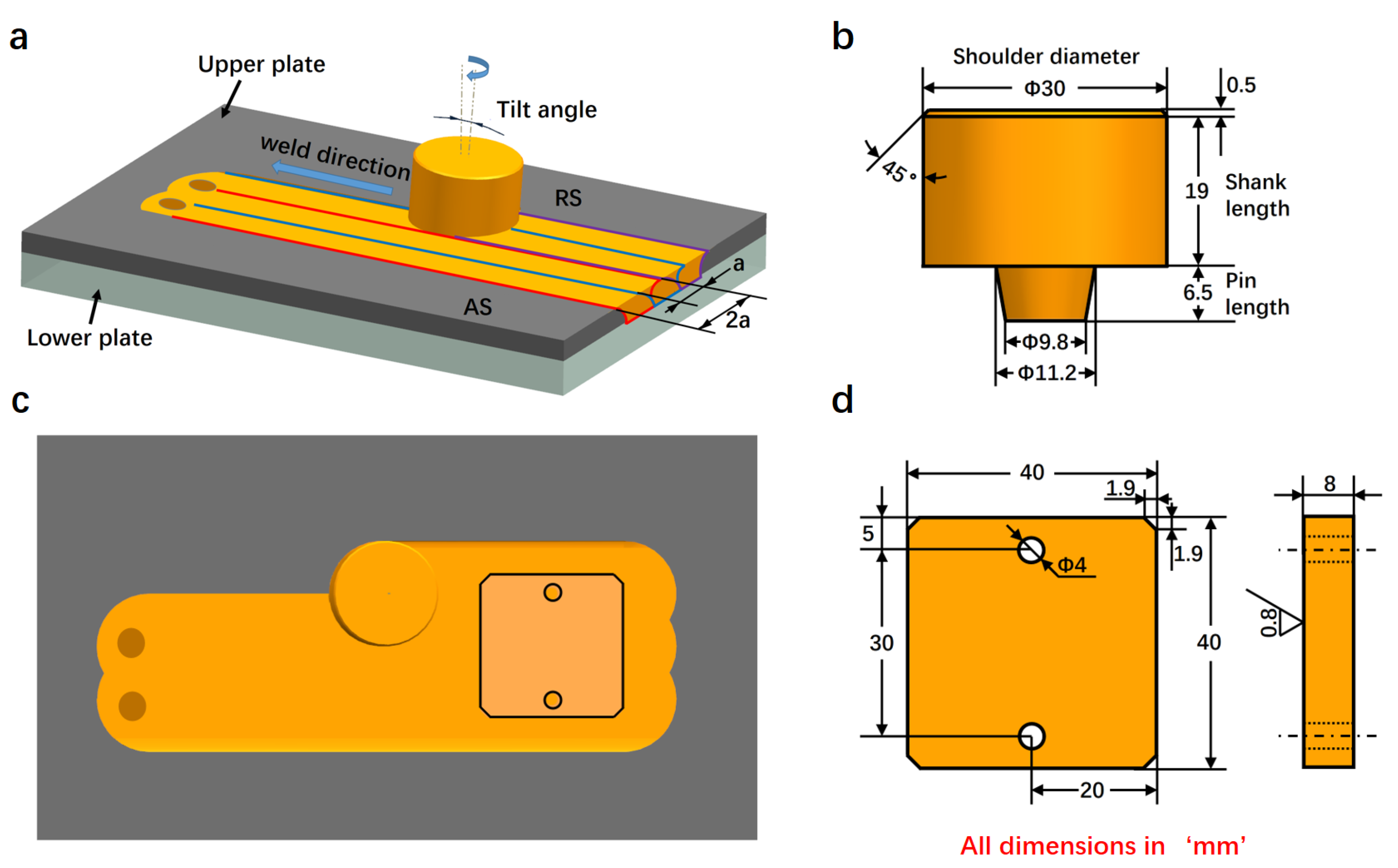
2. Experimental Procedure

2.1. Experimental Materials

In this experiment, the SiCp/ZL101 composite material with 20% SiCp volume fraction was prepared by stir casting method, and the size of the SiC particles was 1000 mesh. The material composition of ZL101 aluminum alloy is shown in Table 1. The prepared composite materials were cut into sheets of size 6 mm × 180 mm × 90 mm by wire cut, ZL101 sheets were cut into sheets of size 9 mm × 180 mm × 90 mm by the wire cut, and the surface roughness of the two sheets was processed to Ra 0.8 by machining technology.
The experimental equipment in this study was a FSW equipment modified from a X35K milling machine from Zhengling (Liuzhou, China), and the FSLW process was adopted to weld SiCp/ZL101 composite plate (upper plate) and ZL101 plate (lower plate) to prepare multiple sets of welding samples. Figure 1a is a schematic diagram of the FSLW process. The overlapping rate of adjacent welding passes was 50%. The detailed welding parameters are shown in Table 2. After the welding samples were prepared, natural aging was carried out for 7 days.
Six friction and wear test specimens were cut from the weld joint of the sample by wire cut. The sampling location is shown in Figure 1c, and the sample size is shown in Figure 1d. The surface roughness of the specimens was treated to Ra0.8 by the machining technology.

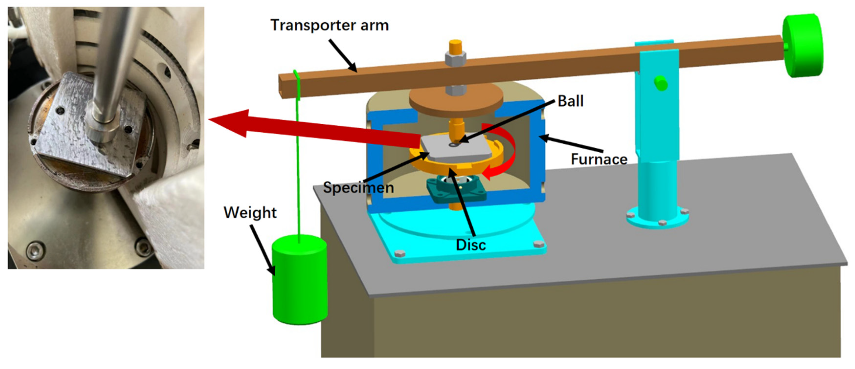
2.2. Friction and Wear Test

The equipment used in this experiment was MMQ-02G ball-on-disk high-temperature friction and wear testing machine from Yihua (Jinan, China), and six specimens were subjected to friction and wear tests in air atmosphere at different temperatures. Figure 2 is a schematic diagram of the experimental device. As can be seen, the specimen was fixed on the rotating disk, and the counter-grinding ball was in contact with the surface of the specimen under the specified load. The distance between the counter-grinding ball and the center of the rotating disc is the friction radius. After the device was heated to the specified temperature in the incubator, the rotating disk drove the friction specimen to perform relative frictional motion with the grinding ball at a specified speed. Si4N3 balls with a diameter of 6 mm were used as the counter-grinding balls, and the test time was 60 min. The test parameters of the six specimens are shown in Table 3. During the experiment, the test parameters such as test force, rotational speed, friction coefficient, temperature, time, etc., were collected and calculated by the computer in real time, and the wear debris was collected after each test.

2.3. Wear Detection and Structural Characterization

After cleaning and drying the friction and wear specimens with alcohol, the MS-M9000 multifunctional friction tester from Huahui (Lanzhou, China) was used to measure the wear extent and wear scar depth of the friction and wear specimens by the surface profile method. Each specimen was measured at four symmetrical parts of the friction ring, and the arithmetic mean value of the four groups of data was taken.
In order to study the microstructure of the wear surface and wear debris, a Quanta 400 scanning electron microscope (SEM) equipped with an energy-dispersive X-ray spectrometer (EDS) (FEI, Eindhoven, The Netherlands) was used to observe the microstructure of the wear surface and wear debris, and the elemental compositions of the wear debris were analyzed by EDS.

3. Results

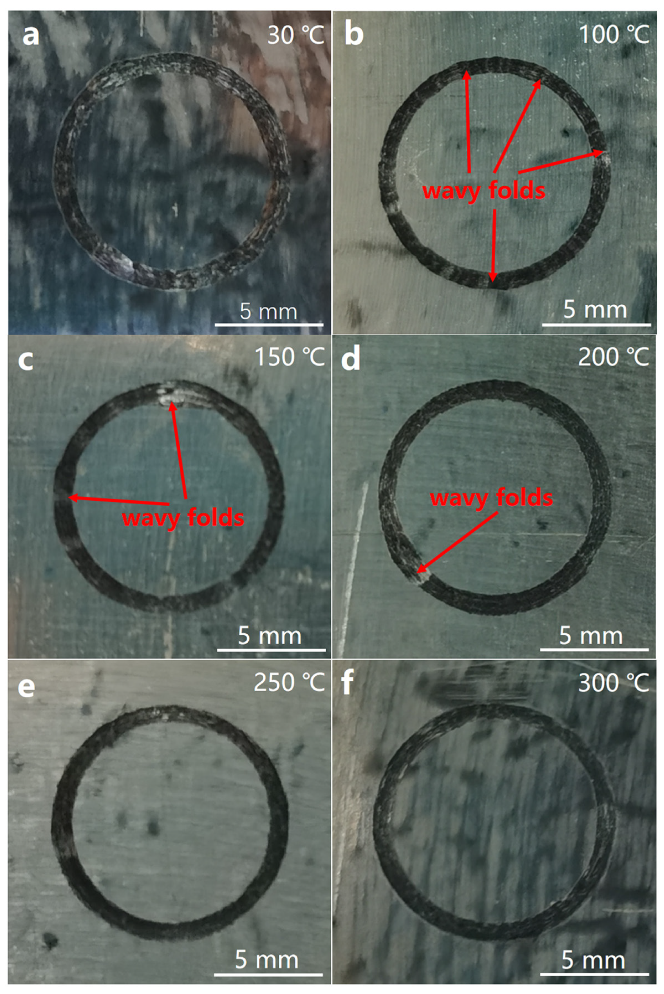
3.1. Macrostructure Morphology of Wear Surface

Figure 3 is a schematic diagram of the macrostructure of the wear surface at 30 °C, 100 °C, 150 °C, 200 °C, 250 °C and 300 °C. As shown in the figure, the wear scar of the 30 °C specimen (Figure 3a) is relatively wide, and the wear surface is rough and uneven, showing a silvery white luster. The wear surface of the specimens from 100 °C to 300 °C is black; the wavy folds caused by extrusion deformation can be clearly observed on the wear surface of the specimen at 100 °C (Figure 3b), and the distribution is relatively dense. The distribution of wavy folds on the wear surface of the 150 °C specimen (Figure 3c) is relatively sparse. The wear surface of the 200 °C specimen (Figure 3d) is relatively flat, with only one obvious wavy fold observed. The wear surfaces of the 250 °C and 300 °C specimens (Figure 3e,f) are relatively flat.

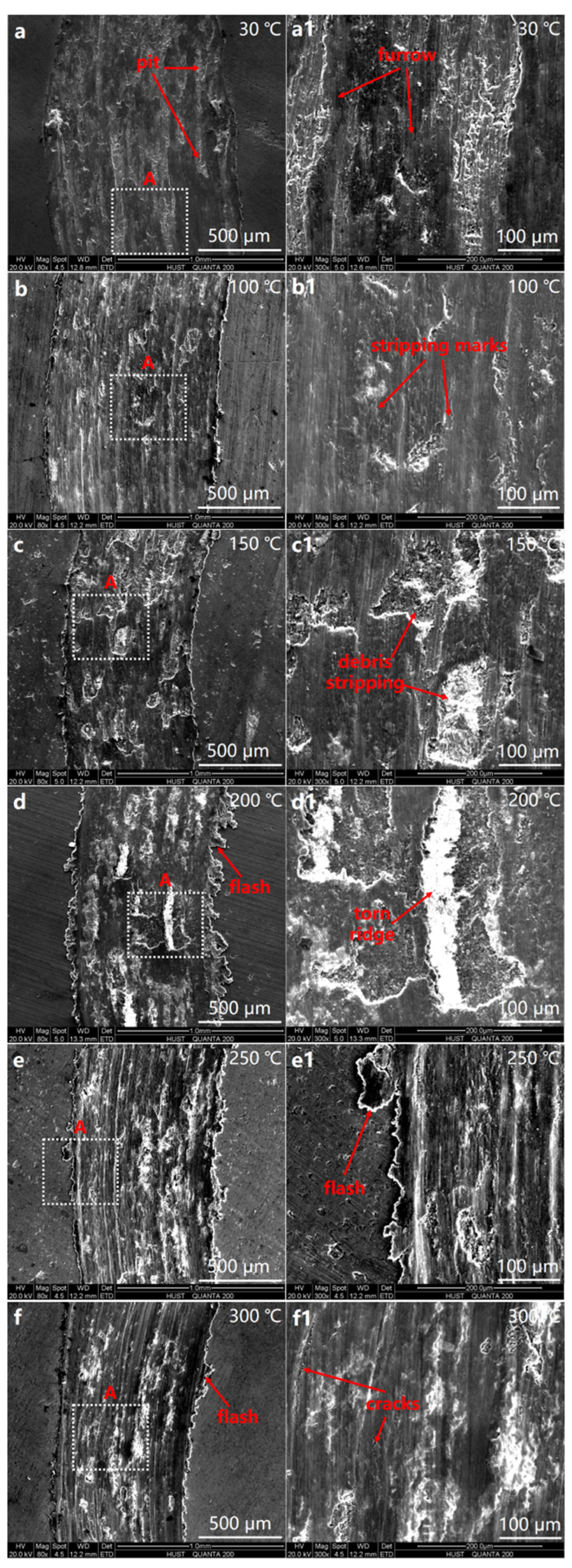
3.2. Microstructure Morphology of Wear Surface

Figure 4 is a schematic diagram of the microstructure morphology of the wear surface at 30 °C, 100 °C, 150 °C, 200 °C, 250 °C and 300 °C. As shown in Figure 4a, there are a large number of pits on the wear surface at 30 °C due to the shedding of wear debris, and these pits are connected to each other, resulting in uneven wear surfaces. The high-magnification image of the SEM (Figure 4a1) shows that there are fine furrows on the surface of the wear scar. The wear surface at 100 °C (Figure 4b,b1) shows obvious traces of plastic deformation due to extrusion, and the amount of wear debris falling off is reduced compared with that at 30 °C, and it begins to show obvious peeling marks. At 150 °C, the amount and area of the wear debris shedding on the wear surface (Figure 4c) increase significantly, and the SEM high-magnification image (Figure 4c1) shows obvious peeling marks. The wear surface above 200 °C shows significant plastic deformation traces. Due to the extrusion of the grinding ball, the metal softened at high temperature overflows at the edge of the wear scar to form an obvious flash-like structure (Figure 4d–f). The high-magnification image of the SEM (Figure 4f1) shows that fatigue cracks are generated on the wear scar surface under the action of cyclic stress.
Figure 5 is a graph of the wear extent curve, wear scar depth curve and average friction coefficient curve at each experimental temperature. As shown in Figure 5a,b, as the temperature increases, the wear extent and wear scar depth first decrease and then increase, and then show a downward trend after reaching the highest level at 150 °C. The wear extent above 200 °C is equivalent to about 35% of the wear extent at room temperature; the wear extent and wear scar depth show the smallest dispersion at 30 °C, and the largest dispersion at 150 °C. As shown in Figure 5c, the average friction coefficient does not show significant differences with the change of temperature, and is stable at around 0.4; the average friction coefficient has the largest dispersion at 300 °C.
Figure 6 is a graph of the friction coefficient changing with time at various experimental temperatures. As shown in the figure, at each experimental temperature, the friction coefficient does not show large fluctuations with time, reflecting a stable friction performance.

3.3. Morphology of Wear Debris

Figure 7 shows SEM micrographs of wear debris at 30 °C, 100 °C, 150 °C, 200 °C, 250 °C and 300 °C. As shown in Figure 7a, the abrasive debris consists of a small amount of large-sized massive abrasive debris and a large amount of powdery abrasive debris at 30 °C. As the temperature increases, the powdery abrasive debris decreases greatly (as shown in Figure 7b). The size of the massive abrasive debris reaches the maximum at 150 °C. As the temperature rises further, the powdery abrasive debris begins to increase, and the size of the debris tends to be consistent (as shown in Figure 7e,f); obvious cracks appear on the surface of the massive wear debris at 150 °C and 200 °C.
An energy-dispersive X-ray spectrometer was used to analyze the composition of the wear debris of 30 °C and 150 °C. As shown in Figure 8, besides the Al and Si elements contained in the matrix material, there are more O elements in the wear debris. Since the grinding balls are Si4N3 ceramic balls with high hardness and stable chemical properties, it shows that the O element in the grinding debris comes from the oxidation of the composite material during the wear process.
An energy-dispersive X-ray spectrometer was used to analyze the composition of the wear debris at 300 °C. As shown in Figure 9, the EDS component analysis shows the presence of Al, Si, O and C. Since the friction and wear experiments were carried out in air atmosphere, the surface of the exfoliated SiC particles was easily stained with the oxide produced by the Al matrix. Therefore, according to the EDS analysis results in Figure 9b, it is judged that the particles in Figure 9a are SiC particles.

4. Discussion

4.1. Effect of Temperature on the Morphology of Wear Scars

The roughness of sliding friction surfaces plays a crucial role in the wear process [45]. When the grinding balls first come into contact with the composite surface, they only make contact at a few rough points where these micro-protrusions cover only a small portion of the surface area. As a result, very high stresses are generated in these small surface areas and wear occurs at these points [46]. Figure 10 is a schematic diagram of the wear surface morphology change from low temperature to high temperature. As shown in Figure 10a, when the temperature is low, the plastic deformation of the contact surface is small, and the uneven contact point cracks and breaks under the cyclic shearing action of the grinding ball; the wear process at 30 °C fits this type (Figure 3a). In addition, due to the higher fracture energy [46], the plastic deformation of the metal caused by wear at 30 °C is small; a silver-white rough wear surface is finally formed. As the temperature increases, the plasticity of the friction surface of the composite material improves; the uneven contact points on the friction surface are fractured due to the large plastic deformation under the sliding shear of the grinding ball and accumulate to the advancing side of the grinding ball. With the increase in accumulation, due to insufficient shear force, the grinding ball will move on over the accumulated metal. Wavy folds are formed on the wear surface under this cyclic friction (as shown at point A in Figure 10b). Since the plasticity of the composite material is further enhanced with the increase in temperature, more metal needs to be accumulated on the advancing side of the grinding ball to generate sufficient shear resistance (Figure 10c). Therefore, the spacing of the wavy folds on the wear surface gradually increases (as shown in Figure 3b–d).
When the temperature reaches 200 °C, the increased plasticity of the composite leads to the improvement of the fluidity, leading to flashing at the edge of the wear scar due to composite spillage (as shown in Figure 4d–f). When the temperature exceeds 250 °C, the wear surface exhibits extensive plastic deformation. Therefore, the wear groove track formed parallel to the sliding direction is relatively clear (as shown in Figure 4e,f).

4.2. Effect of Temperature on Wear Mechanisms

Friction Stir Processing improves the defects in the as-cast composites [25] and promotes the performance improvement of the composites [47]. Figure 11a is the photo of the cross-section of the FSLW joint; Figure 11b is the SEM photograph of the as-cast composite material area at point A not affected by FSP in Figure 11a; Figure 11c is the SEM photo of the nugget area at point B in Figure 11a. As shown in Figure 11b, the SiC particles are agglomerated and unevenly distributed, and there are casting shrinkage defects in the as-cast SiCp/ZL101. The microstructure of the as-cast SiCp/ZL101 is significantly improved after FSP (Figure 11c). The SiC particles are refined and evenly distributed, and casting shrinkage cavities are eliminated. The composite material after stirring is denser, and the wear surface maintains better compactness and continuity [46,48]. Therefore, the friction process at each temperature is relatively stable, and the fluctuation range of the friction coefficient is small. A stable friction coefficient can lead to better braking effects, such as better thermal stability, the reduction of the vibration of the braking system, low noise, controllable braking safety and so on [37,38].
When the friction and wear test was carried out at 30 °C, the micro-protrusions on the surface of the composite material were plastically deformed under the cutting action of the grinding ball and the rotating torque; a large amount of heat was generated locally, resulting in the partial oxidation of the material and it falling off the surface to form wear debris, leading to pitting on the wear surface. This phenomenon exhibited characteristics of oxidation wear. The fine scratches on the wear surface along the sliding direction were mainly caused by the reinforcement particles shed from the matrix [49], indicating that abrasive wear also occurred during the sliding friction process [50]. It is worth noting that the stirred composite materials show very shallow grooves after sliding wear, which may be attributed to the following two factors. First, the SiC particle becomes smaller and has a good interfacial bond with the Al matrix after the stirring treatment. Good interfacial bonding persists at 30 °C and allows load transfer across the particle/matrix interface. Therefore, only a small number of SiC particles fracture and detach from the Al matrix. Secondly, since there is no obvious accumulation of reinforced particles after the stirring treatment [51], the evenly distributed small-sized and high-hardness SiC particles improve the hardness, strength and wear resistance of the composite material [52], which can act as a hard barrier against scratching and plowing by abrasive particles [53]. These two factors lead to the formation of shallow grooves in the wear surface.
The plasticity of the wear surface is improved with the increase in temperature. Figure 12 is a schematic diagram of fatigue crack growth on the wear surface. As shown in the figure, due to the repeated extrusion of the grinding ball, microcracks nucleate at the stress concentration of the friction surface, gradually break through the wear surface, and then grow and connect with each other during the sliding process. Eventually, the surface metal will fall off and become wear debris. This statement is confirmed by the cracks on the wear debris in Figure 7c,d and the pits with irregular edges formed by the shedding of wear debris in Figure 4c1,d1. The wear surface exhibits fatigue wear behavior at this stage. The initiation and growth of the fatigue cracks are further accelerated with the increase in temperature; the size of the wear debris is larger; the wear extent and wear scar depth reach the maximum at 150 °C. The fatigue wear leads to the shedding of large pieces of wear debris at 150 °C (Figure 7c), and the wear surface is rough and uneven. Therefore, the fluctuation range of the friction coefficient becomes significantly larger after 1500s (Figure 6c), which shows significant differences with the friction coefficient curves at other temperatures. As shown in Figure 3c, there were wavy folds caused by plastic deformation on the wear surface at 150 °C. When the surface profiling method was used to detect the wear extent and wear scar depth, if the sampling part was just near the wavy folds, it would cause a large deviation between different measurements. Therefore, the large dispersion of wear extent and wear scar depth at 150 °C can be attributed to the combination of the high roughness of the wear surface and the morphology of the measurement sampling part.
In Figure 4d1, the irregular tear ridges are shown after the wear debris breaks away at 200 °C, and the wear scar depth is significantly smaller, showing the characteristics of adhesive wear [53], indicating that the further improvement of the plasticity of the composite material at high temperature leads to the transition of the wear behavior to adhesive wear. As the temperature further increases, the softening of the Al matrix leads to the cracking or loosening of the SiC particles. As shown in Figure 9, the EDS component analysis of the abrasive debris at 300 °C shows the presence of small-sized SiC particles and oxide particles. Figure 13 is a schematic diagram of the sliding friction process at high temperature. As shown in Figure 13b, these small-sized SiC particles and oxides aggregate between the wear surface and the grinding ball, and gradually form a mechanically mixed layer on the wear surface under the action of cyclic load [54]. Elastic deformation occurs on the wear surface at high temperature [55], and this mechanically mixed layer is more likely to cause shear instability on the sliding friction surface [56,57]. Meanwhile, the wear surface maintains better compactness and continuity due to the denser composite material after stirring [46,48], and is not easily damaged by the shear force of the mechanical mixing layer, which further reduces the severity of the microplowing action caused by interactions between abrasive particles. The combined effect of appealing factors leads to a reduced wear rate at elevated temperatures. On the other hand, the plastic deformation resistance of the composite decreases due to the increase in temperature. The wear debris adhered to the grinding ball forms a clear furrow on the wear surface; the wear does not progress further, due to the lubrication of the high-hardness mechanical mixed layer [58]. Therefore, there were no pits on the wear surface caused by the shedding of large-sized wear debris at 250 °C and 300 °C, and the depth of the wear scars did not continue to increase.

5. Conclusions

(1)
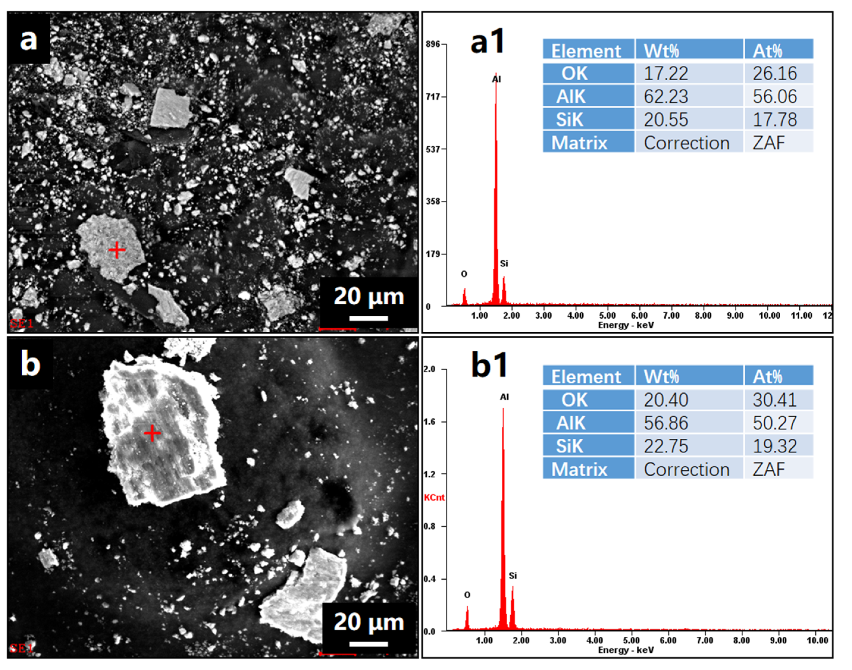
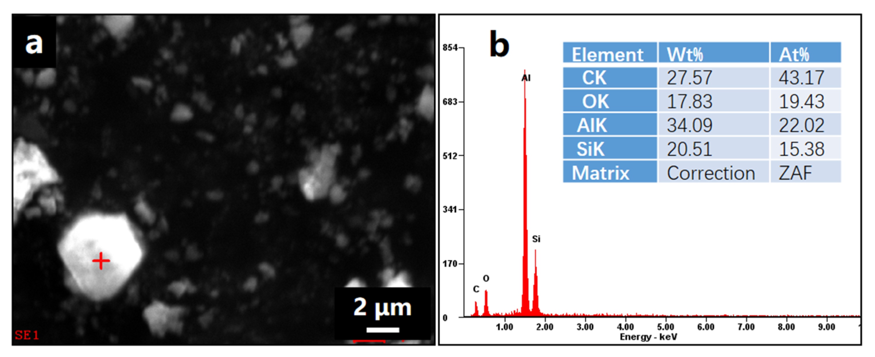
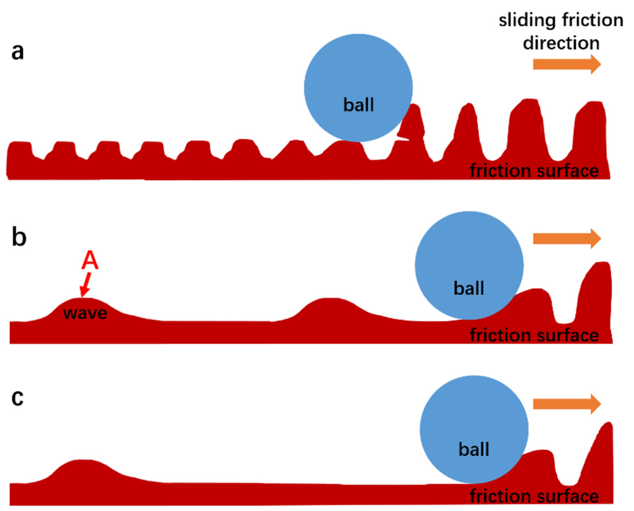
The wear scars of the specimen at 30 °C were relatively wide, and the wear surface was rough and uneven. The wear scars of the specimens at 100 °C to 300 °C were black, and obvious wavy folds could be observed on the wear surface. The distribution of wavy folds was denser and decreased with increasing temperature. The wear surfaces showed significant signs of plastic deformation at temperatures above 200 °C. The size of the wear debris reached its maximum at 150 °C, and obvious cracks appeared on the surface of the wear debris. Then, the powdery abrasive debris began to increase, and the size of the wear debris tended to be consistent. The O element was detected in the wear debris at each temperature.
(2)
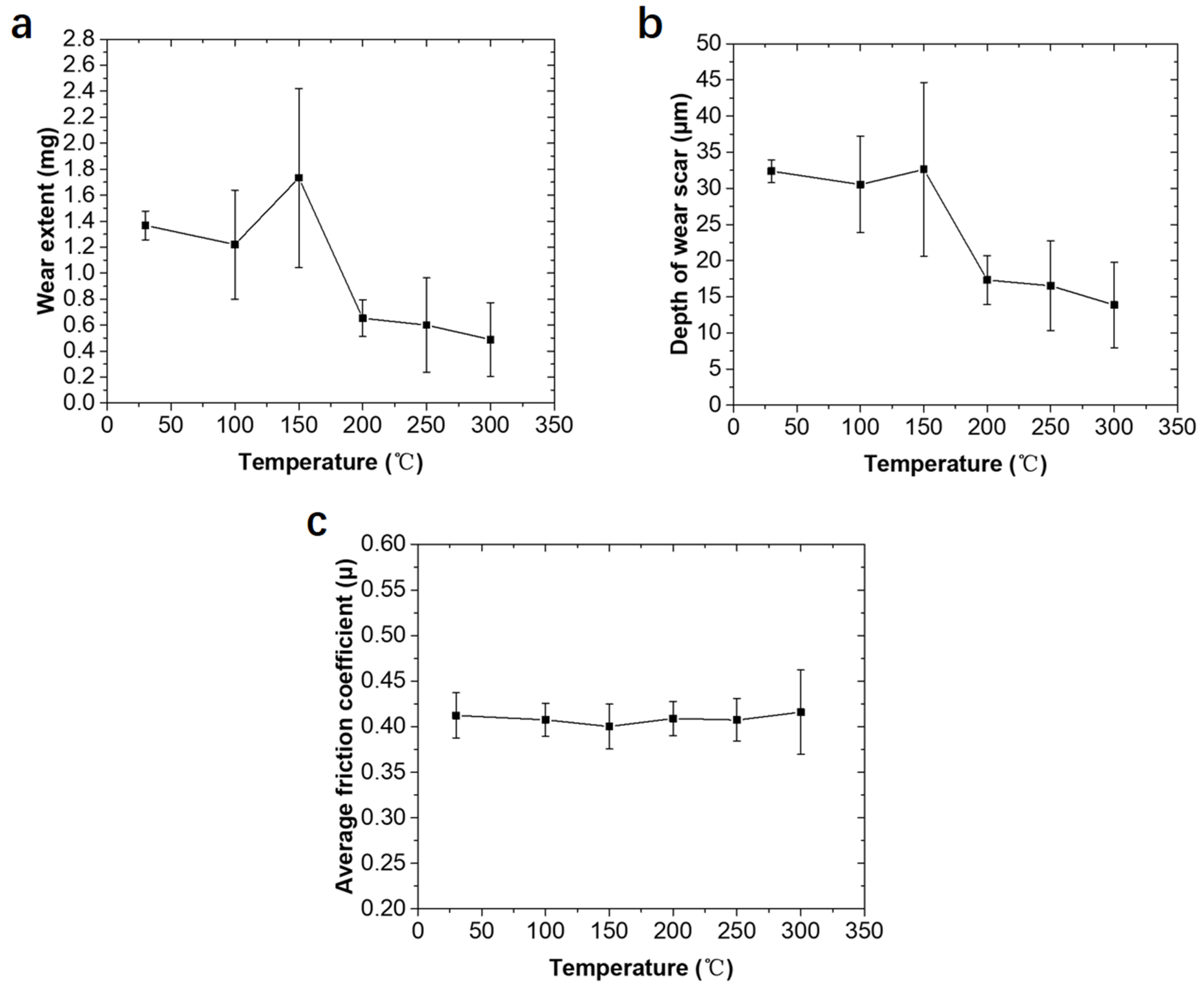
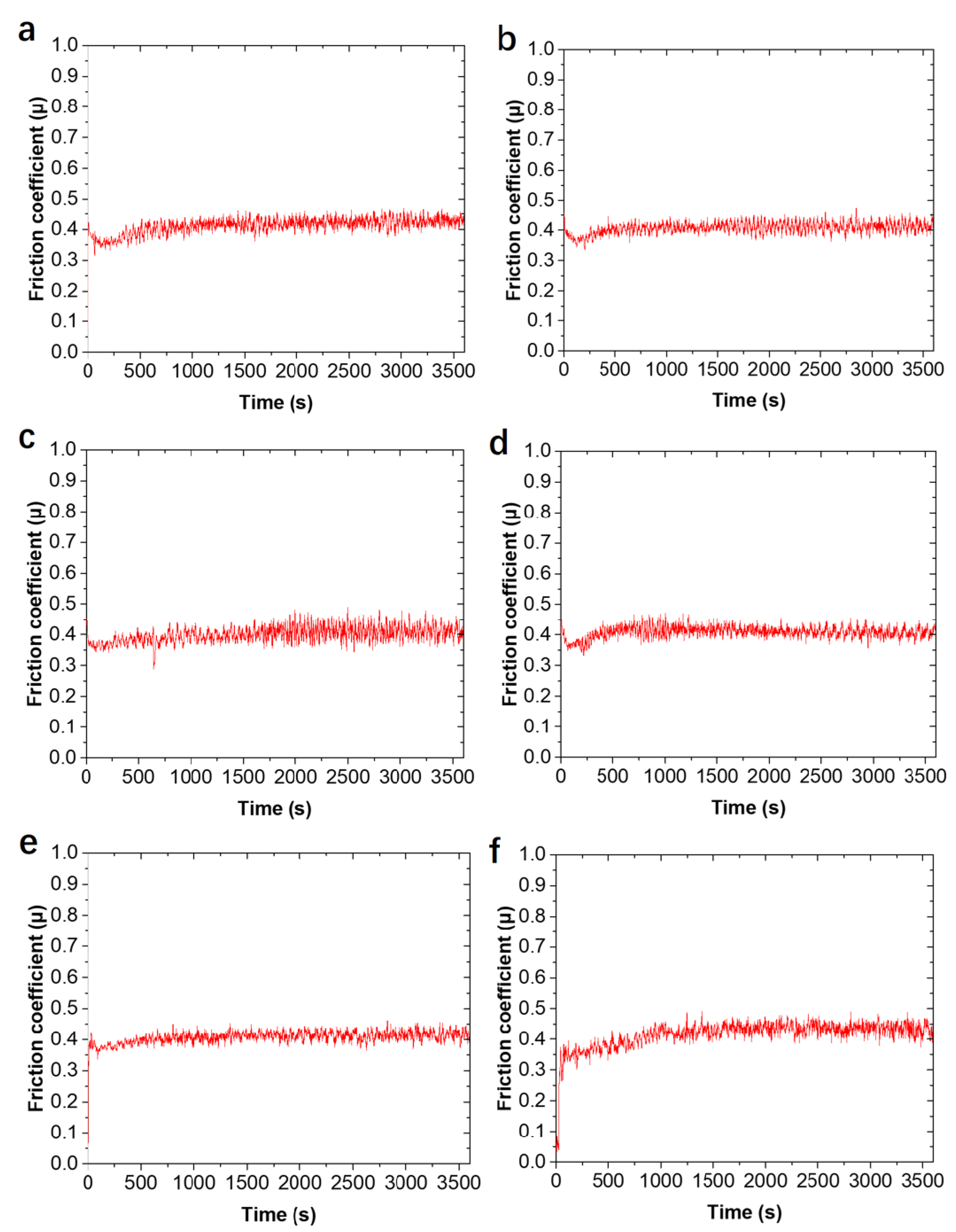
The friction process at each temperature was relatively stable; the friction coefficient did not change much. The average friction coefficient changed slightly and was stable at around 0.4. The wear extent and the depth of wear scars increased with increasing temperature, reaching the highest at 150 °C, and then began to decrease. The wear extent above 200 °C was equivalent to about 35% of the wear extent at room temperature.
(3)
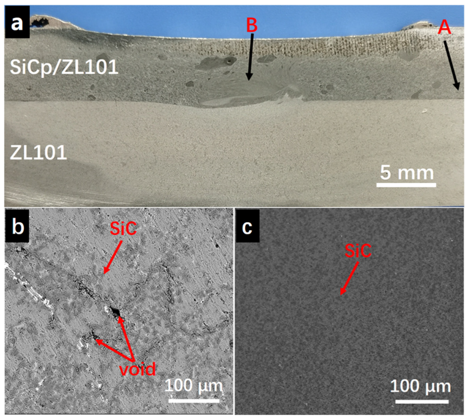
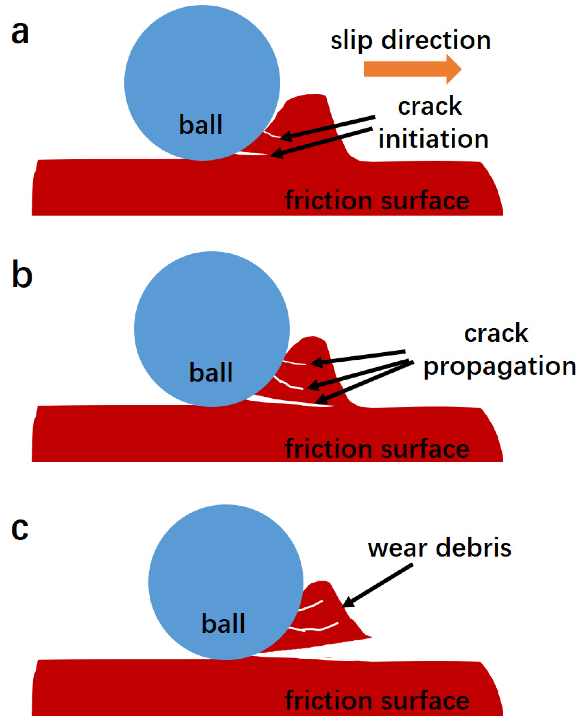
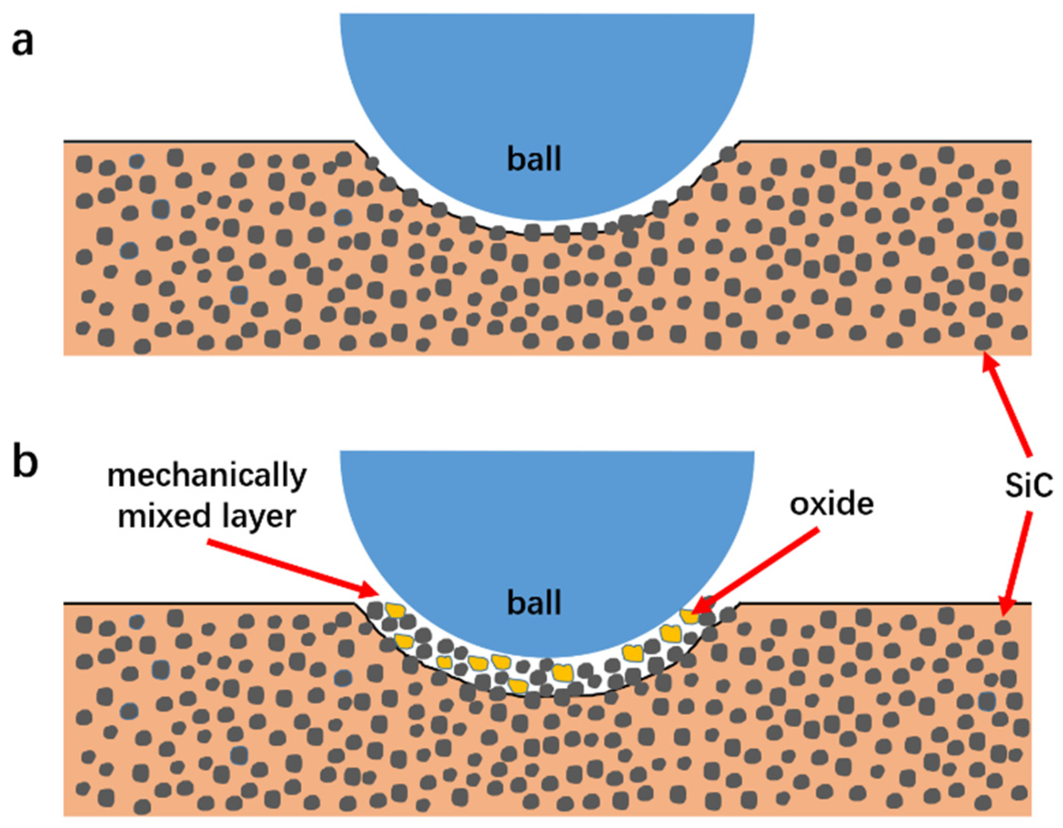
The wear mechanisms were mainly oxidation wear and abrasive wear at 30 °C. As the temperature increased, the wear debris fell off under the propagation of the fatigue cracks caused by the action of the cyclic shearing of the grinding ball; fatigue wear was the main form at this stage. When the temperature reached 200 °C, it began to show the characteristics of adhesive wear. Due to the gradual formation of a mechanical mixed layer containing SiC particles and oxides on the wear surface at high temperature, it exhibited high-temperature lubrication characteristics and better high-temperature friction and wear performance.

Author Contributions

Conceptualization, B.Y. and G.L.; methodology, H.D.; investigation, B.Y. and G.L.; writing—original draft preparation, B.Y.; writing—review and editing, W.J. and D.L.; visualization, W.J.; Supervision, D.L. All authors have read and agreed to the published version of the manuscript.

Funding

This research was funded by National Key Research and Development Program of China [No. 2020YFB2008300, 2020YFB2008304], the National Natural Science Foundation of China [Nos. 52075198 and 52271102].

Institutional Review Board Statement

Not applicable.

Informed Consent Statement

Not applicable.

Data Availability Statement

Data presented in this article are available at request from the corresponding author.

Acknowledgments

The authors gratefully acknowledge the support provided by the Analytical and Testing Center, HUST.

Conflicts of Interest

The authors declare no conflict of interest.

References

  1. Jiang, W.; Zhu, J.; Li, G.; Guan, F.; Yu, Y.; Fan, Z. Enhanced mechanical properties of 6082 aluminum alloy via SiC addition combined with squeeze casting. J. Mater. Sci. Technol. 2021, 88, 119–131. [Google Scholar] [CrossRef]
  2. Zhu, J.; Jiang, W.; Li, G.; Guan, F.; Yu, Y.; Fan, Z. Microstructure and mechanical properties of SiCnp/Al6082 aluminum matrix composites prepared by squeeze casting combined with stir casting. J. Mater. Process. Technol. 2020, 283, 116699. [Google Scholar] [CrossRef]
  3. Geng, R.; Qiu, F.; Jiang, Q.C. Reinforcement in Al Matrix Composites: A Review of Strengthening Behavior of Nano-Sized Particles. Adv. Eng. Mater. 2018, 20, 13. [Google Scholar] [CrossRef]
  4. Wasekar, M.K.; Khond, M.P. A Composite Material an alternative for manufacturing of Automotive Disc Brake: A Review. IOP Conf. Ser. Mater. Sci. Eng. 2021, 1126, 012067. [Google Scholar] [CrossRef]
  5. Jin, Y.X.; Wang, X.Y.; Tong, Q.Q.; Chen, H.M.; Lee, J.M. High-Temperature Dry Sliding Friction and Wear Characteristics of As-Cast SiCP/A356 Composite. Adv. Mater. Res. 2013, 690–693, 318–322. [Google Scholar] [CrossRef]
  6. Dasgupta, R. Aluminium alloy-based metal matrix composites: A potential material for wear resistant applications. Int. Sch. Res. Not. 2012, 2012, 594573. [Google Scholar] [CrossRef] [Green Version]
  7. Moustafa, E.B. Dynamic characteristics study for surface composite of AMMNCs matrix fabricated by friction stir process. Materials 2018, 11, 1240. [Google Scholar] [CrossRef] [Green Version]
  8. Khalil, A.M.; Loginova, I.S.; Solonin, A.N.; Mosleh, A.O. Controlling liquation behavior and solidification cracks by continuous laser melting process of AA-7075 aluminum alloy. Mater. Lett. 2020, 277, 128364. [Google Scholar] [CrossRef]
  9. Khalil, A.M.; Loginova, I.S.; Pozdniakov, A.V.; Mosleh, A.O.; Solonin, A.N. Evaluation of the Microstructure and Mechanical Properties of a New Modified Cast and Laser-Melted AA7075 Alloy. Materials 2019, 12, 3430. [Google Scholar] [CrossRef] [Green Version]
  10. Ahmed, F.; Srivastava, S.; Agarwal, A.B. Synthesis & Characterization of Al-Ti-Cr MMC as friction material for disc brakes application. Mater. Today Proc. 2017, 4, 405–414. [Google Scholar] [CrossRef]
  11. Mhaske, M.S.; Shirsat, D.U.M. Investigations of Tribological Behaviour of Al-SiC MMC for Automobile Brake Pad. In Proceedings of the TRIBOINDIA-2018: An International Conference on Tribology, Mumbai, India, 13–15 December 2018. [Google Scholar] [CrossRef]
  12. Kolli, M.; Devaraju, A.; Saikumar, G.; Kosaraju, S. Electrical Discharge Machining of SiC Reinforced 6061-T6 Aluminum Alloy Surface Composite Fabricated by Friction Stir Processing. E3S Web Conf. 2021, 309, 01044. [Google Scholar] [CrossRef]
  13. Venkatachalam, G.; Arumugam, K. Mechanical Behaviour of Aluminium Alloy Reinforced with Sic/Fly Ash/Basalt Composite for Brake Rotor. Polym. Polym. Compos. 2017, 25, 203–208. [Google Scholar] [CrossRef]
  14. Firouz, F.M.; Mohamed, E.; Lotfy, A.; Daoud, A.; Abou El-Khair, M.T. Thermal expansion and fatigue properties of automotive brake rotor made of AlSi–SiC composites. Mater. Res. Express 2020, 6, 1265d1262. [Google Scholar] [CrossRef]
  15. P, S.; Natarajan, H.K.; Kumar J., P. Study of silicon carbide-reinforced aluminum matrix composite brake rotor for motorcycle application. Int. J. Adv. Manuf. Technol. 2018, 94, 1461–1475. [Google Scholar] [CrossRef]
  16. Daoud, A.; Abou El-khair, M.T. Wear and friction behavior of sand cast brake rotor made of A359-20vol% SiC particle composites sliding against automobile friction material. Tribol. Int. 2010, 43, 544–553. [Google Scholar] [CrossRef]
  17. Hekner, B.; Myalski, J.; Valle, N.; Botor-Probierz, A.; Sopicka-Lizer, M.; Wieczorek, J. Friction and wear behavior of Al-SiC(n) hybrid composites with carbon addition. Compos. Part B Eng. 2017, 108, 291–300. [Google Scholar] [CrossRef]
  18. Sika, R.; Rogalewicz, M.; Popielarski, P.; Czarnecka-Komorowska, D.; Przestacki, D.; Gawdzińska, K.; Szymański, P. Decision Support System in the Field of Defects Assessment in the Metal Matrix Composites Castings. Materials 2020, 13, 3552. [Google Scholar] [CrossRef]
  19. Sharma, V.; Singla, Y.; Gupta, Y.; Raghuwanshi, J. Post-processing of metal matrix composites by friction stir processing. AIP Conf. Proc. 2018, 1953, 090062. [Google Scholar] [CrossRef]
  20. Fadavi Boostani, A.; Tahamtan, S.; Jiang, Z.Y.; Wei, D.; Yazdani, S.; Azari Khosroshahi, R.; Taherzadeh Mousavian, R.; Xu, J.; Zhang, X.; Gong, D. Enhanced tensile properties of aluminium matrix composites reinforced with graphene encapsulated SiC nanoparticles. Compos. Part A Appl. Sci. Manuf. 2015, 68, 155–163. [Google Scholar] [CrossRef]
  21. Zhou, D.; Qiu, F.; Jiang, Q. The nano-sized TiC particle reinforced Al–Cu matrix composite with superior tensile ductility. Mater. Sci. Eng. A 2015, 622, 189–193. [Google Scholar] [CrossRef]
  22. Liu, Q.; Ke, L.; Liu, F.; Huang, C.; Xing, L. Microstructure and mechanical property of multi-walled carbon nanotubes reinforced aluminum matrix composites fabricated by friction stir processing. Mater. Des. 2013, 45, 343–348. [Google Scholar] [CrossRef]
  23. Velavan, K.; Palanikumar, K. Effect of Silicon Carbide (SiC) on Stir Cast Aluminium Metal Matrix Hybrid Composites—A Review. Appl. Mech. Mater. 2015, 766–767, 293–300. [Google Scholar] [CrossRef]
  24. Eskandari, H.; Taheri, R. A Novel Technique for Development of Aluminum Alloy Matrix/TiB2/Al2O3 Hybrid Surface Nanocomposite by Friction Stir Processing. Procedia Mater. Sci. 2015, 11, 503–508. [Google Scholar] [CrossRef] [Green Version]
  25. Moustafa, E.B.; Mikhaylovskaya, A.V.; Taha, M.A.; Mosleh, A.O. Improvement of the microstructure and mechanical properties by hybridizing the surface of AA7075 by hexagonal boron nitride with carbide particles using the FSP process. J. Mater. Res. Technol. 2022, 17, 1986–1999. [Google Scholar] [CrossRef]
  26. Avettand-Fènoël, M.-N.; Simar, A. A review about Friction Stir Welding of metal matrix composites. Mater. Charact. 2016, 120, 1–17. [Google Scholar] [CrossRef]
  27. Zuo, L.; Zhao, X.; Li, Z.; Zuo, D.; Wang, H. A review of friction stir joining of SiCp/Al composites. Chin. J. Aeronaut. 2020, 33, 792–804. [Google Scholar] [CrossRef]
  28. Vijayavel, P.; Rajkumar, I.; Sundararajan, T. Surface characteristics modification of lm25 aluminum alloy–5% sic particulate metal matrix composites by friction stir processing. Met. Powder Rep. 2021, 76, 140–151. [Google Scholar] [CrossRef]
  29. Vijayavel, P.; Sundararajan, T.; Rajkumar, I.; Ananthakumar, K. Effect of tool diameter ratio of tapered cylindrical profile pin on wear characteristics of friction stir processing of Al-Si alloy reinforced with SiC ceramic particles. Met. Powder Rep. 2021, 76, 75–89. [Google Scholar] [CrossRef]
  30. Mohamadigangaraj, J.; Nourouzi, S.; Jamshidi Aval, H. Statistical modelling and optimization of friction stir processing of A390-10 wt% SiC compo-cast composites. Measurement 2020, 165, 108166. [Google Scholar] [CrossRef]
  31. Kumar, A.; Pal, K.; Mula, S. Simultaneous improvement of mechanical strength, ductility and corrosion resistance of stir cast Al7075-2% SiC micro- and nanocomposites by friction stir processing. J. Manuf. Process. 2017, 30, 1–13. [Google Scholar] [CrossRef]
  32. Kurtyka, P.; Rylko, N.; Tokarski, T.; Wójcicka, A.; Pietras, A. Cast aluminium matrix composites modified with using FSP process – Changing of the structure and mechanical properties. Compos. Struct. 2015, 133, 959–967. [Google Scholar] [CrossRef]
  33. Butola, R.; Tyagi, L.; Singari, R.M.; Murtaza, Q.; Kumar, H.; Nayak, D. Mechanical and wear performance of Al/SiC surface composite prepared through friction stir processing. Mater. Res. Express 2021, 8, 016520. [Google Scholar] [CrossRef]
  34. Aruri, D.; Adepu, K.; Adepu, K.; Bazavada, K. Wear and mechanical properties of 6061-T6 aluminum alloy surface hybrid composites [(SiC+Gr) and (SiC+Al2O3)] fabricated by friction stir processing. J. Mater. Res. Technol. 2013, 2, 362–369. [Google Scholar] [CrossRef] [Green Version]
  35. Devaraju, A.; Kumar, A.; Kumaraswamy, A.; Kotiveerachari, B. Influence of reinforcements (SiC and Al2O3) and rotational speed on wear and mechanical properties of aluminum alloy 6061-T6 based surface hybrid composites produced via friction stir processing. Mater. Des. 2013, 51, 331–341. [Google Scholar] [CrossRef]
  36. Rana, H.G.; Badheka, V.J.; Kumar, A. Fabrication of Al7075/B4C surface composite by novel friction stir processing (FSP) and investigation on wear properties. Procedia Technol. 2016, 23, 519–528. [Google Scholar] [CrossRef] [Green Version]
  37. Shin, K.; Brennan, M.J.; Oh, J.E.; Harris, C.J. Analysis of disc brake noise using a two-degree-of-freedom model. J. Sound Vib. 2002, 254, 837–848. [Google Scholar] [CrossRef]
  38. Brake vibration and noise: Reviews, comments, and proposals. Int. J. Mater. Prod. Technol. 1997, 12, 496–513. [CrossRef]
  39. Xia, P.; Wu, Y.; Yin, T.; Xie, K.; Tan, Y. Formation mechanism of TiC–Al2O3 ceramic reinforcements and the influence on the property of ZL101 composites. Ceram. Int. 2022, 48, 2577–2584. [Google Scholar] [CrossRef]
  40. Luo, X.; Han, Y.; Li, Q.; Hu, X.; Xue, L. Microstructure and Properties of ZL101 Alloy Affected by Substrate Movement Speed of a Novel Semisolid Continuous Micro Fused-Casting for Metal Process. J. Wuhan Univ. Technol. -Mater. Sci. Ed. 2018, 33, 715–719. [Google Scholar] [CrossRef]
  41. Cheng, S.-j.; Zhao, Y.-h.; Hou, H.; Jin, Y.-c.; Guo, X.-x. Preparation of semi-solid ZL101 aluminum alloy slurry by serpentine channel. Trans. Nonferrous Met. Soc. China 2016, 26, 1820–1825. [Google Scholar] [CrossRef]
  42. Cui, H.-c.; Lu, F.-g.; Peng, K.; Tang, X.-h.; Yao, S. Research on electron beam welding of in situ TiB2p/ZL101 composite. J. Shanghai Jiaotong Univ. 2010, 15, 479–483. [Google Scholar] [CrossRef]
  43. Wan, J.; Yan, H.; Xu, D. Rheological study of semi-solid TiAl3/ZL101 composites prepared by ultrasonic vibration. Int. J. Mater. Res. 2015, 106, 1244–1249. [Google Scholar] [CrossRef]
  44. Chen, L.; Zhao, Y.; Yan, F.; Hou, H. Statistical investigations of serpentine channel pouring process parameters on semi-solid ZL101 aluminum alloy slurry using response surface methodology. J. Alloys Compd. 2017, 725, 673–683. [Google Scholar] [CrossRef]
  45. Rabinowicz, E.; Tanner, R.I. Friction and Wear of Materials. J. Appl. Mech. 1966, 33, 479. [Google Scholar] [CrossRef]
  46. Saadatmand, M.; Mohandesi, J.A. Comparison Between Wear Resistance of Functionally Graded and Homogenous Al-SiC Nanocomposite Produced by Friction Stir Processing (FSP). J. Mater. Eng. Perform. 2014, 23, 736–742. [Google Scholar] [CrossRef]
  47. Manickam, A.; Kuppusamy, R.; Jayaprakasham, S.; Santhanam, S.K.V. Multi Response Optimization of Friction Stir Process Parameters on AA2024/SiC Composite Fabricated Using Friction Stir Processing. In Proceedings of the ASME 2021 International Mechanical Engineering Congress and Exposition, Online, 1–5 November 2021. [Google Scholar]
  48. Cui, G.; Qian, Y.; Bian, C.; Gao, G.; Hassani, M.; Liu, Y.; Kou, Z. CoCrNi matrix high-temperature wear resistant composites with micro- and nano-Al2O3 reinforcement. Compos. Commun. 2020, 22, 100461. [Google Scholar] [CrossRef]
  49. Roy, P.; Singh, S.; Pal, K. Enhancement of mechanical and tribological properties of SiC- and CB-reinforced aluminium 7075 hybrid composites through friction stir processing. Adv. Compos. Mater. 2019, 28, 1–18. [Google Scholar] [CrossRef]
  50. Kumar, A.; Mahapatra, M.M.; Jha, P.K. Modeling the abrasive wear characteristics of in-situ synthesized Al–4.5%Cu/TiC composites. Wear 2013, 306, 170–178. [Google Scholar] [CrossRef]
  51. Gangil, N.; Maheshwari, S.; Siddiquee, A.N. Novel Use of Distribution Facilitators and Time–Temperature Range for Strengthening in Surface Composites on AA7050-T7451. Metallogr. Microstruct. Anal. 2018, 7, 561–577. [Google Scholar] [CrossRef]
  52. Ostovan, F.; Amanollah, S.; Toozandehjani, M.; Shafiei, E. Fabrication of Al5083 surface hybrid nanocomposite reinforced by CNTs and Al2O3 nanoparticles using friction stir processing. J. Compos. Mater. 2019, 54, 1107–1117. [Google Scholar] [CrossRef]
  53. Huang, G.; Hou, W.; Li, J.; Shen, Y. Development of surface composite based on Al-Cu system by friction stir processing: Evaluation of microstructure, formation mechanism and wear behavior. Surf. Coat. Technol. 2018, 344, 30–42. [Google Scholar] [CrossRef]
  54. Muratoğlu, M.; Aksoy, M. Abrasive wear of 2124Al–SiC composites in the temperature range 20–200°C. J. Mater. Process. Technol. 2006, 174, 272–276. [Google Scholar] [CrossRef]
  55. Kumar, S.; Panwar, R.S.; Pandey, O.P. Effect of dual reinforced ceramic particles on high temperature tribological properties of aluminum composites. Ceram. Int. 2013, 39, 6333–6342. [Google Scholar] [CrossRef]
  56. Rosenfield, A.R. A shear instability model of sliding wear. Wear 1987, 116, 319–328. [Google Scholar] [CrossRef]
  57. Alexeyev, N.M. On the motion of material in the border layer in solid state friction. Wear 1990, 139, 33–48. [Google Scholar] [CrossRef]
  58. Tyagi, L.; Butola, R.; Jha, A.K. Mechanical and tribological properties of AA7075-T6 metal matrix composite reinforced with ceramic particles and aloevera ash via Friction stir processing. Mater. Res. Express 2020, 7, 066526. [Google Scholar] [CrossRef]
Figure 1. (a) Schematic diagram of FSLW; (b) Schematic diagram of the size of the stirring pin; (c) Schematic diagram of the sampling location of the friction and wear specimen; (d) Schematic diagram of the sizes of the friction and wear specimen.
Metals 13 00003 g001
Figure 2. Schematic diagram of the friction and wear test device.
Metals 13 00003 g002
Figure 3. (af) Macrostructures of the wear surfaces of 30 °C, 100 °C, 150 °C, 200 °C, 250 °C and 300 °C.
Metals 13 00003 g003
Figure 4. (af) Low magnification SEM micrographs of the microstructure of the wear surface at 30 °C, 100 °C, 150 °C, 200 °C, 250 °C and 300 °C; (a1f1) High magnification SEM micrographs of the structure of area A in a–f.
Metals 13 00003 g004
Figure 5. (a) Wear curves at 30 °C, 100 °C, 150 °C, 200 °C, 250 °C and 300 °C; (b) Wear scar depth curves at 30 °C, 100 °C, 150 °C, 200 °C, 250 °C and 300 °C; (c) Curves of the average friction coefficient at 30 °C, 100 °C, 150 °C, 200 °C, 250 °C and 300 °C.
Metals 13 00003 g005
Figure 6. (af) Curves of friction coefficient versus time at 30 °C, 100 °C, 150 °C, 200 °C, 250 °C and 300 °C.
Metals 13 00003 g006
Figure 7. (af) SEM micrographs of wear debris of 30 °C, 100 °C, 150 °C, 200 °C, 250 °C and 300 °C.
Metals 13 00003 g007
Figure 8. (a,a1) The EDS composition analysis of wear debris of 30 °C, the red plus sign in (a) is the EDS sampling point; (b,b1) EDS composition analysis of wear debris of 150 °C, the red plus sign in (b) is the EDS sampling point.
Metals 13 00003 g008
Figure 9. (a,b) The EDS analysis result of wear debris at 300 °C, the red plus sign in (a) is the EDS sampling point.
Metals 13 00003 g009
Figure 10. (a) Schematic diagram of the change of the wear surface morphology during the friction and wear process at room temperature; (b) Schematic diagram of the formation of wavy folds on the wear surface when the temperature of the friction and wear test increased; (c) The temperature of the friction and wear test was further increased; the spacing of the wavy folds on the wear surface increases.
Metals 13 00003 g010
Figure 11. (a) Schematic diagram of the cross-section of FSLW joint; (b) SEM photograph of the as-cast composite material area at point A not affected by FSP in Figure 11a; (c) SEM photo of the nugget area at point B in Figure 11a.
Metals 13 00003 g011
Figure 12. (a) Fatigue crack initiation on the wear surface; (b) Fatigue crack growth on the wear surface; (c) Fatigue cracks penetrated through the wear surface, and wear debris fell off.
Metals 13 00003 g012
Figure 13. (a) The SiC particles started to loosen and detach from the matrix during sliding friction at high temperature; (b) SiC particles and oxides aggregated on the wear surface to form a mechanically mixed layer.
Metals 13 00003 g013
Table 1. Chemical composition of the ZL101 aluminum alloy (wt.%).
Aluminum AlloyCSiMnMoCrNiMgAlFe
ZL101-6.5~7.5≤0.35---0.25~0.45Bal-
Table 2. The parameters of the FSLW process.
No.Speed (rpm)Welding Speed (mm/min)Pressing Amount (mm)Welding PassTool Tilt Angle (°)
137535.50.1513.5
Table 3. The parameters of the friction and wear test.
No.Speed (r/min)Temperature (°C)Load (N)Radius of Friction (mm)
11503065
215010065
315015065
415020065
515025065
615030065
Disclaimer/Publisher’s Note: The statements, opinions and data contained in all publications are solely those of the individual author(s) and contributor(s) and not of MDPI and/or the editor(s). MDPI and/or the editor(s) disclaim responsibility for any injury to people or property resulting from any ideas, methods, instructions or products referred to in the content.

