
Study on Construction Molding Technology of Long-Span Space Truss Suspended Dome Structure

 , ,
, ,
Abstract
:1. Introduction
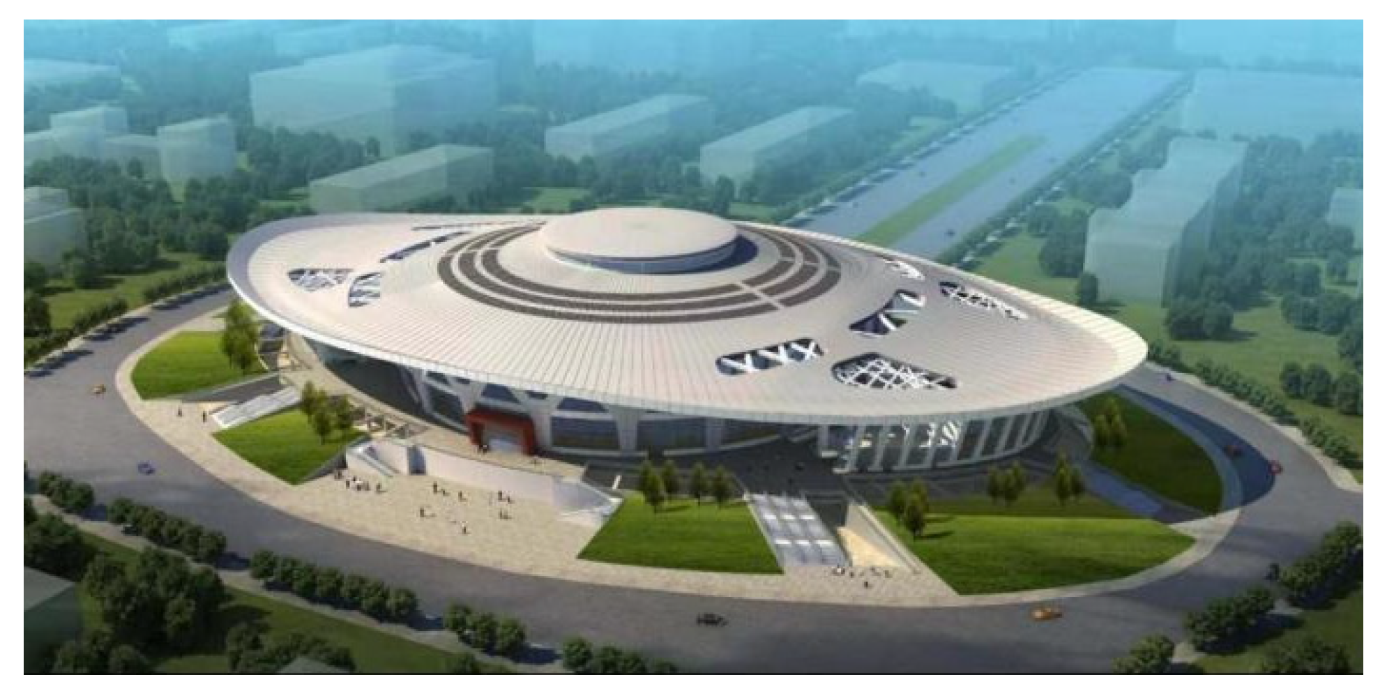
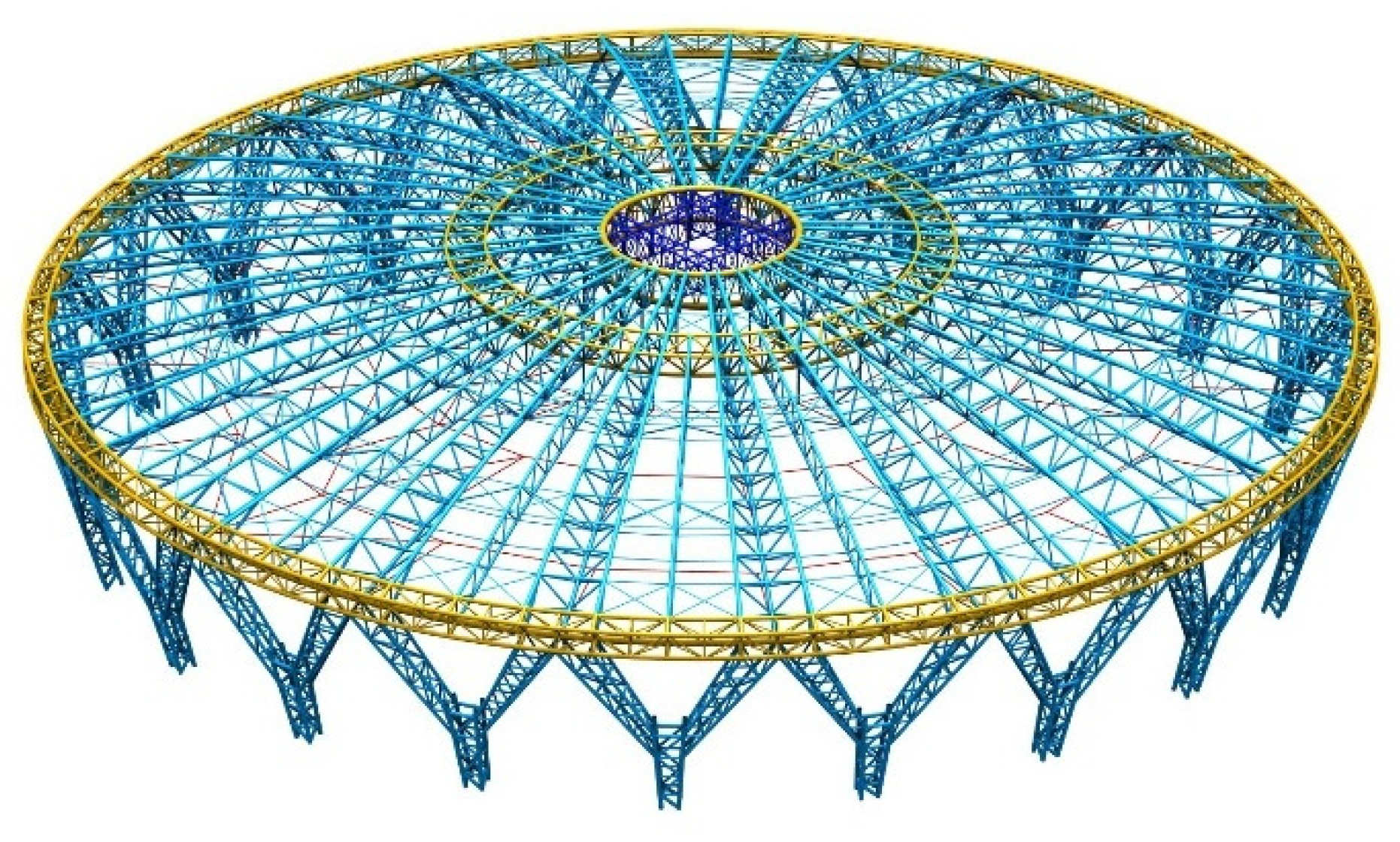
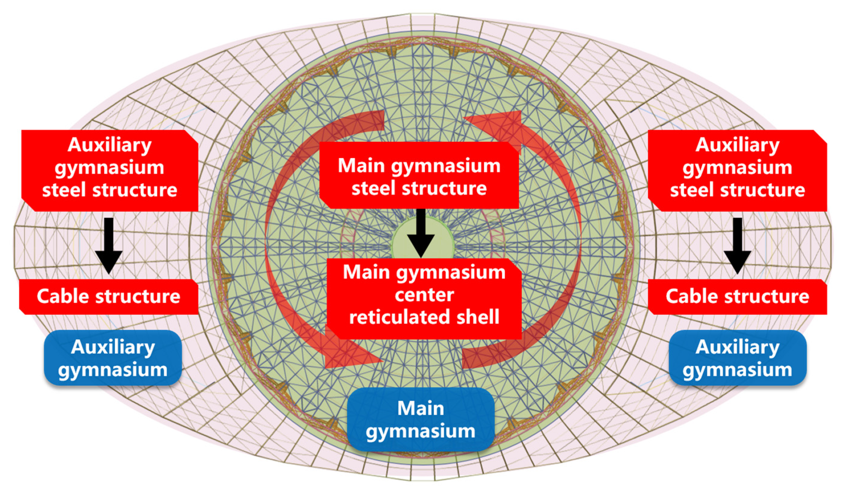
2. Project Overview
3. Construction Scheme
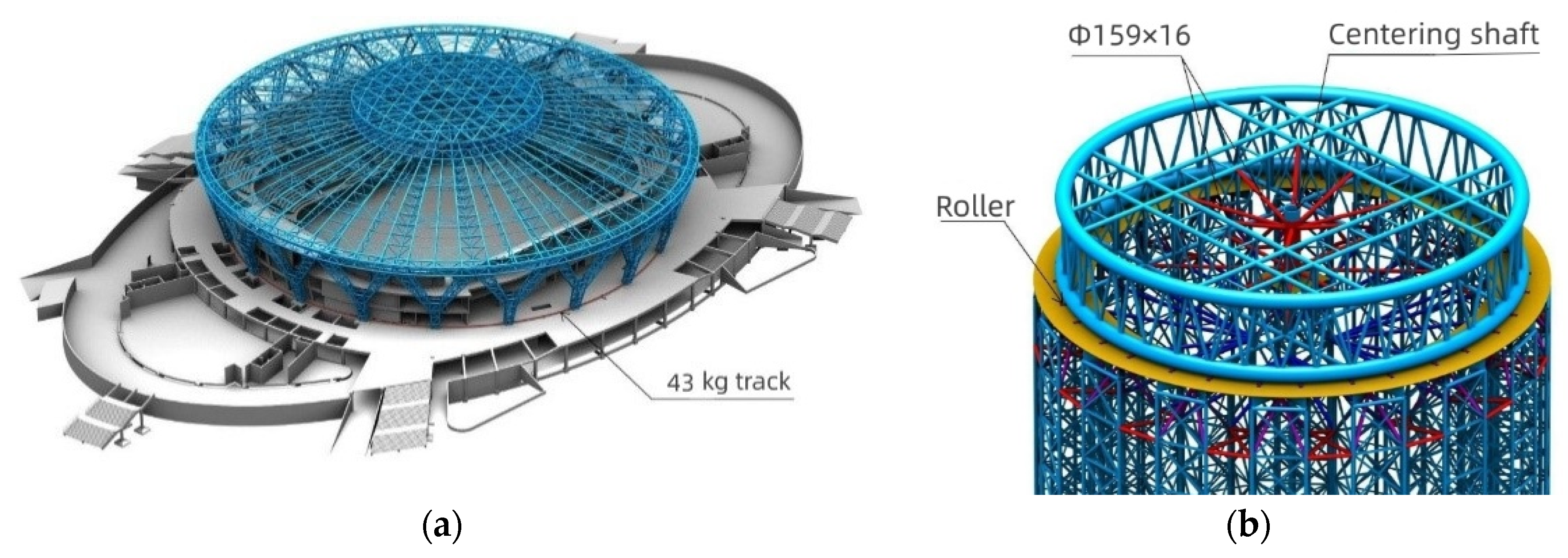
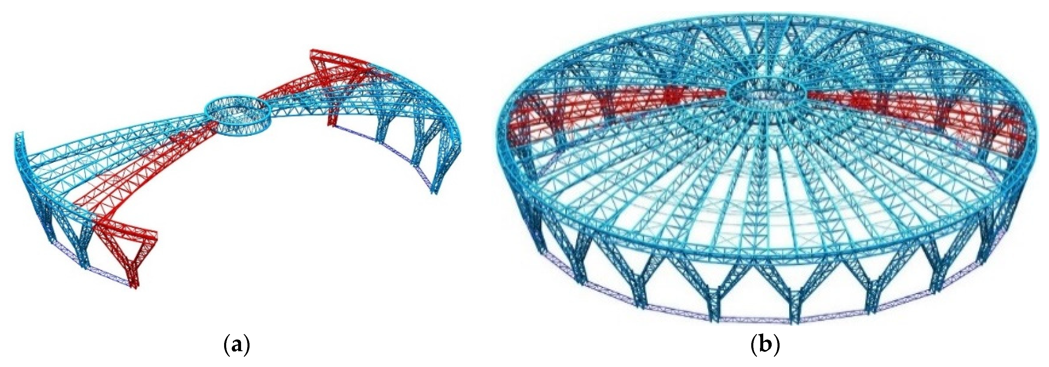
3.1. Steel Structure Slip Construction in the Main Gymnasium
3.1.1. Scheme Selection
3.1.2. Slip Unit Division
3.1.3. Slip System Principle
3.1.4. Unloading of Steel Structure in the Main Gymnasium
3.2. Installation of Steel Structure in the Auxiliary Gymnasium
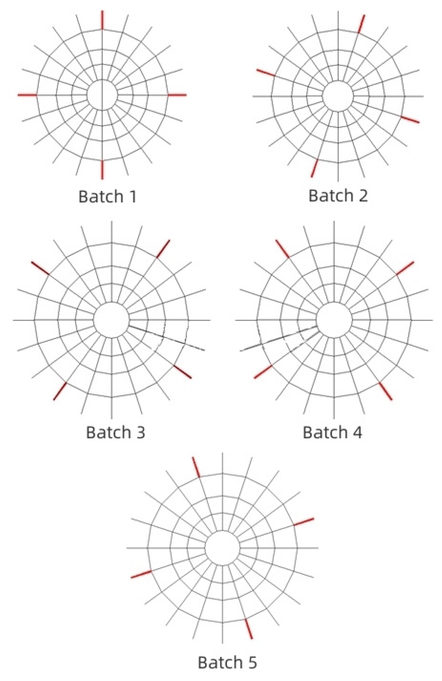
3.3. Cable Structure Installation
4. Construction Process Simulation
4.1. Analysis of Slip Construction Process
- Structural self-weight was mainly considered in construction simulation. Because self-weight is disadvantageous to structures subjected to dynamic load, the subitem coefficient for the load was taken as 1.4, and the load subitem coefficient was taken as 1.0 when checking structural displacement.
- The laced columns and trusses were simulated using beam units, and the outer ring track slippers’ position was considered hinged.
- The slipper was checked using the finite element software ANSYS, with the unit type selected as Solid185.
- The inner ring-supported tire frame had good overall performance, and the vertical deformation during the slip process was small. In order to simplify the calculation, the inner ring-supported tire frame was ignored, and the central ring truss was added with restricted Z-direction translation and X and Y axial rotation constraints.
4.2. Analysis of Cable Structure Tension Construction Process
- By considering the node weight in the reticulated shell, the value of the self-weight coefficient was enlarged to 1.05.
- The cable structure was defined as the tension unit; the brace was defined as the beam element; the beam end constraint was released; and the prestress was applied to the structure by changing the temperature.
5. Analysis of Construction Process Results
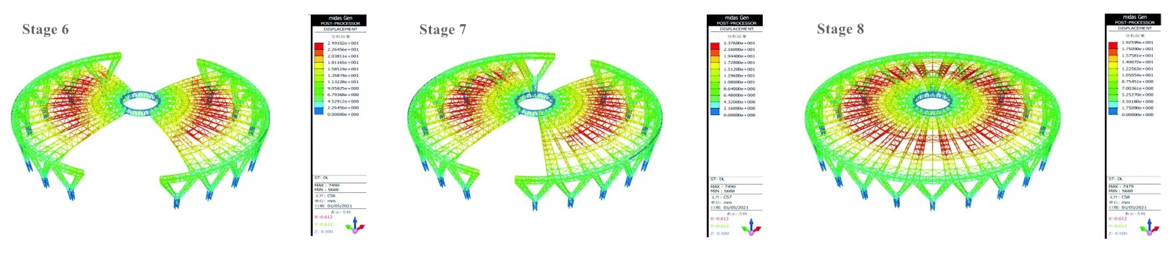
5.1. Slip Construction Process
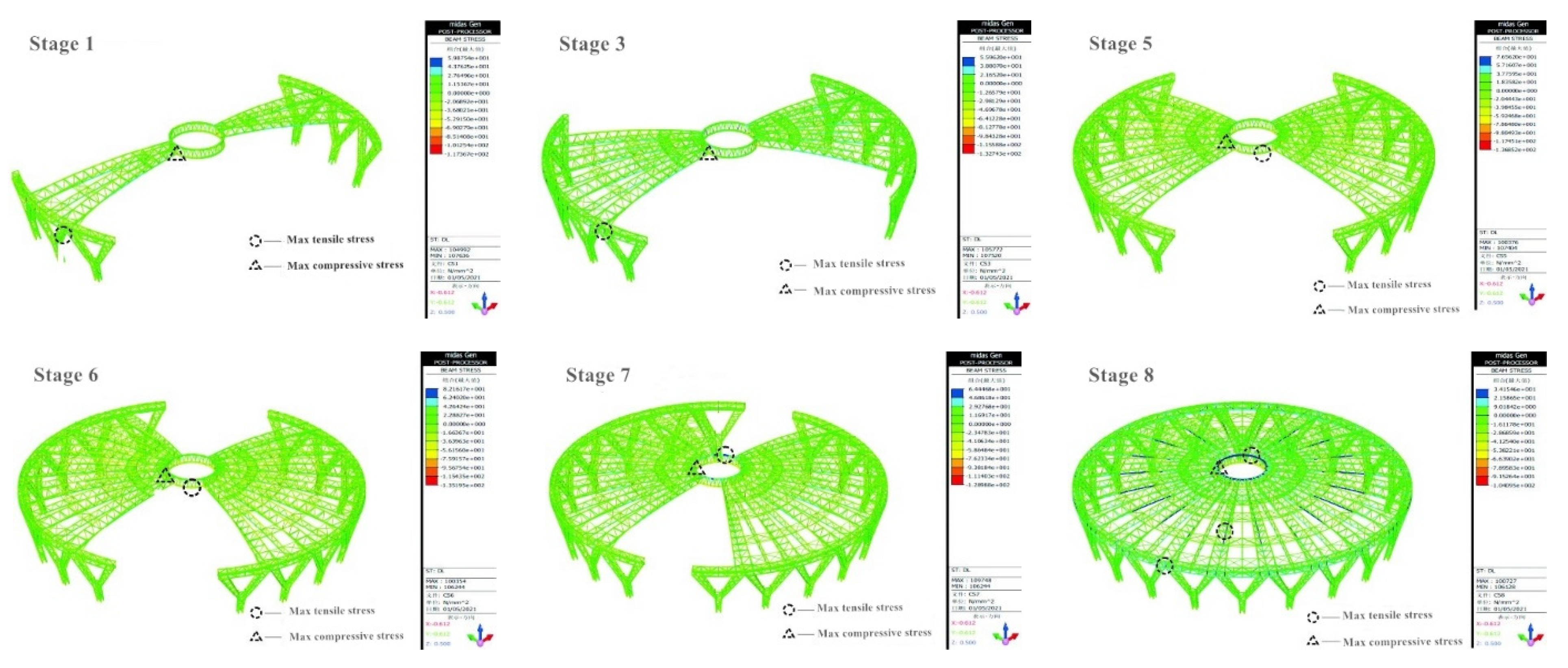
5.1.1. Stress Analysis
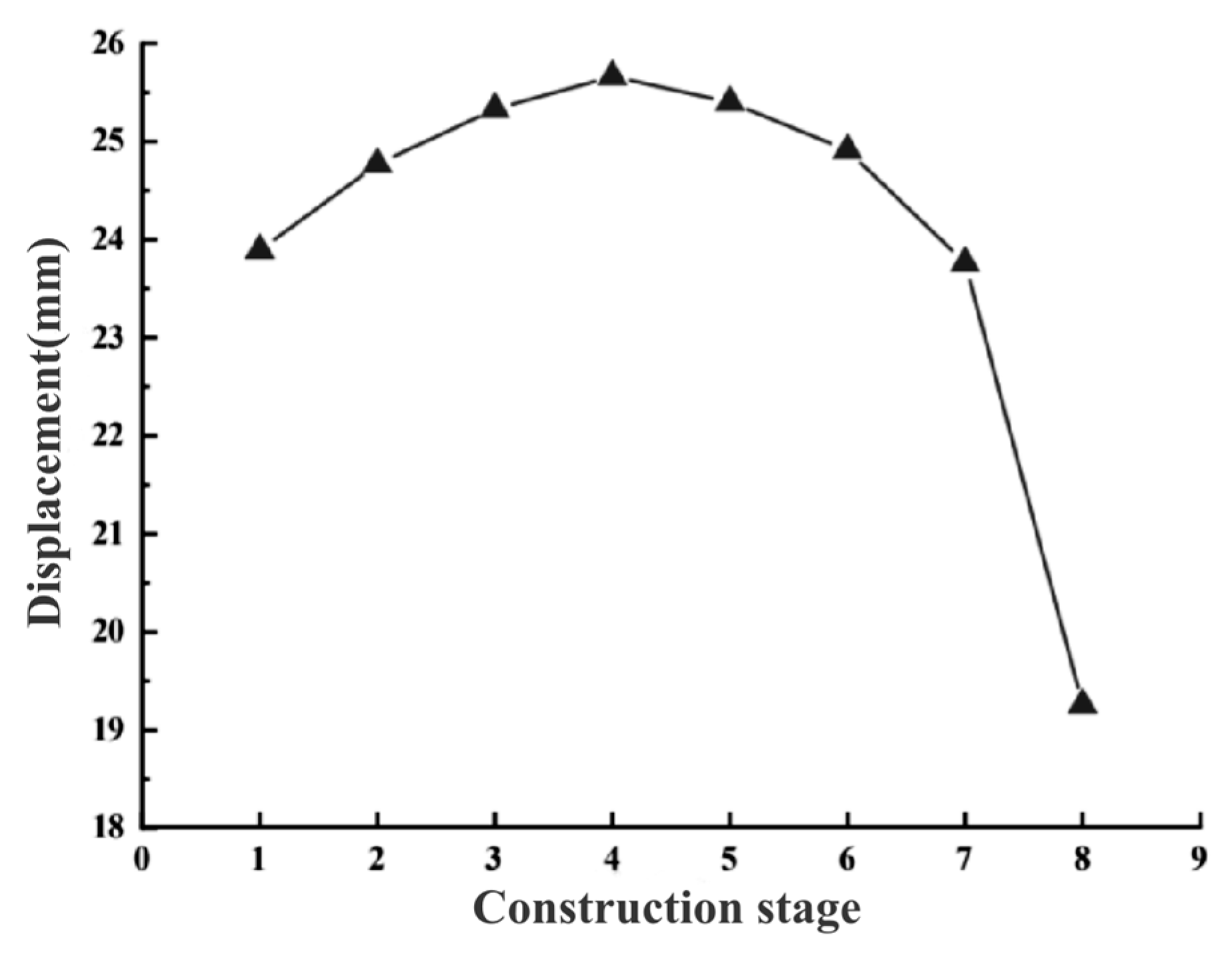
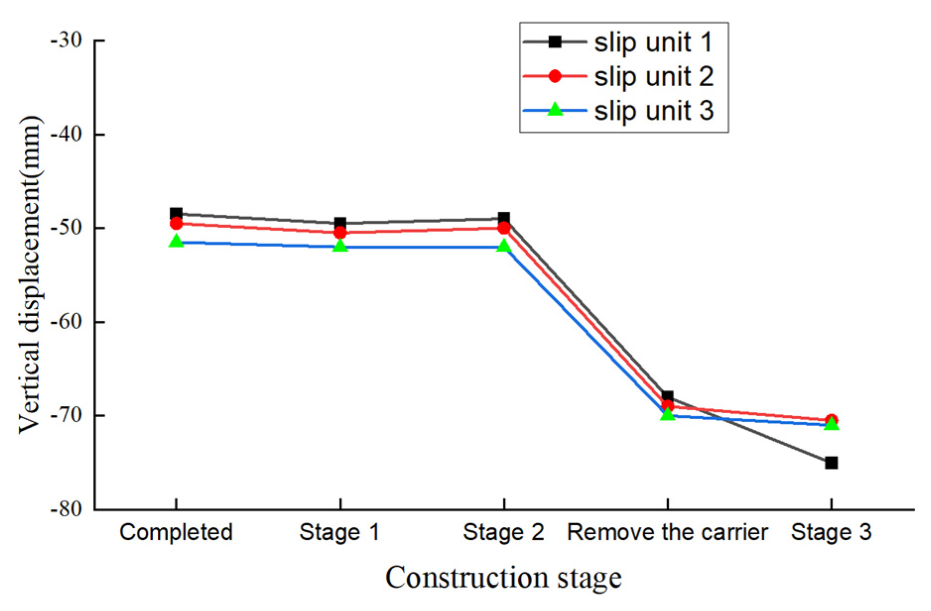
5.1.2. Displacement Analysis
5.1.3. Tire Frame Checking
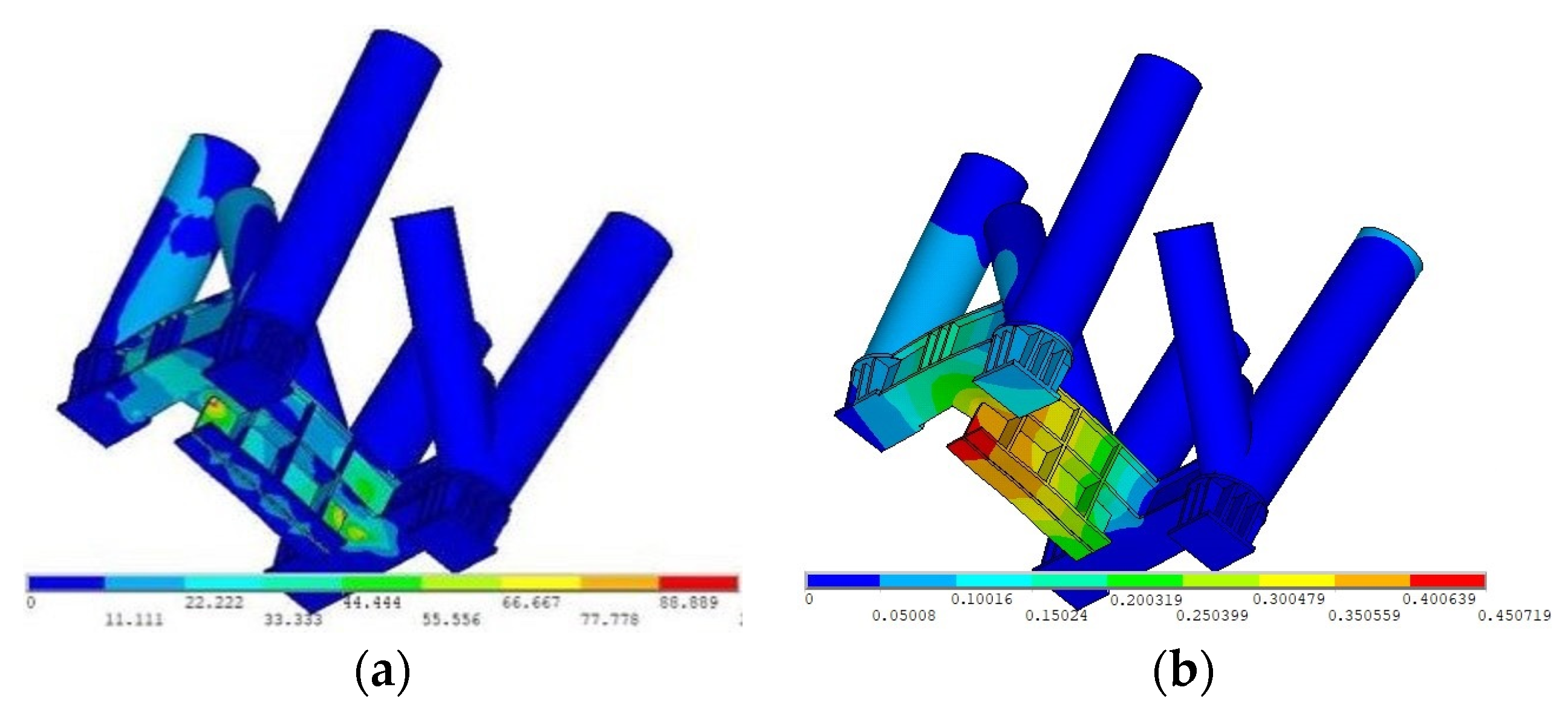
5.1.4. Slipper Checking
5.2. Construction Process of Cable Structure
- Before the completion of the first two tension stages without removing the central tire frame, the vertical deformation of the steel structure was small, with a maximum deformation of 20 mm. After removing the central tire frame and completing the third tension stage, the maximum deformation of the steel structure increased rapidly to 55 mm, but the deformation value was below the limit of the construction specifications. Hence, it meets the construction requirements;
- During tension installation, the steel structure’s maximum tensile and compressive stresses were 62 MPa and 74 MPa, respectively;
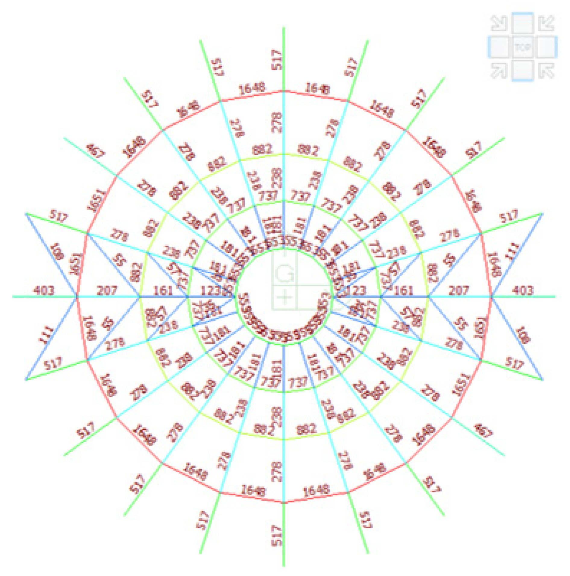
- After removing the central tire frame and completing the third tension stage, the maximum tension of the annular cable was 1648 kN, and that of the radial cable was 517 kN;
- After the completion of tension, the value of cable force gradually increased from inside to outside, and the cable force distribution was more uniform.
- In the first tension stage, the cables were tensioned in batches of up to 10% of the designed tension force, which slightly influenced the displacement and stress of the steel structure in the main gymnasium;
- In the second tension stage, the cables were tensioned in batches of up to 70% of the designed tension, which could improve the vertical displacement of the roof truss of the main gymnasium by a minimum amplitude;
- In the third tension stage, the cables were tensioned in batches to design tension. From the result, it can be seen that it had a very limited influence on structural displacement.
5.3. Auxiliary Gymnasium Construction Process
6. Comparison between Simulation and Monitoring Results
6.1. Comparative Analysis of Stress
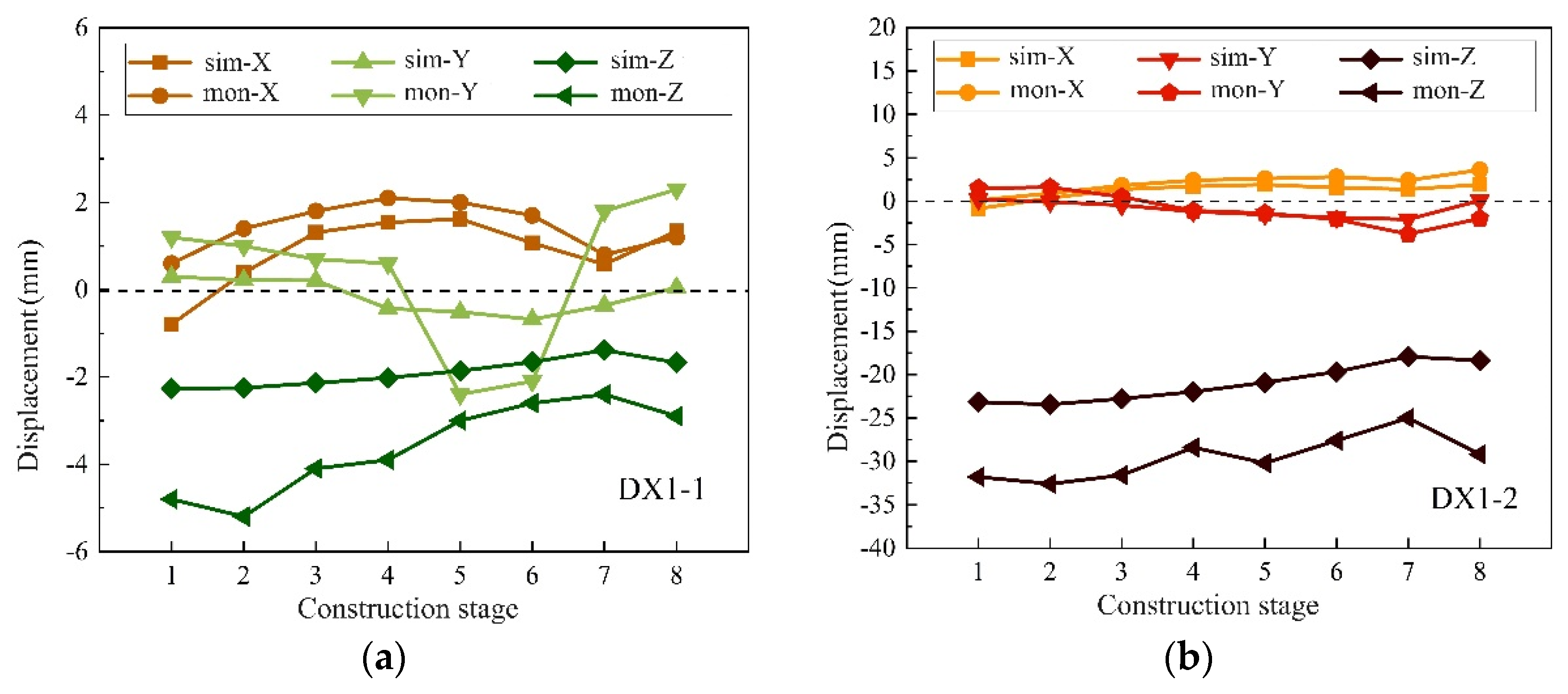
6.2. Displacement Comparison Analysis
7. Conclusions
- The maximum deformation of the long-span space truss suspended dome structure increased from 23.89 mm to 25.40 mm and finally stabilized at 19.26 mm as the construction process gradually stabilized, and the internal force of the early bar was increasing. This indicates that the structural stiffness was gradually formed during the construction process, and the weak parts of the structure were changed compared to the one-time forming, meaning that it is necessary to analyze the construction process;
- The finite element simulation results were relatively close to the measured data; the calculation result of stress and displacement was consistent with the variation trend of the simulation curve, and the stress characteristics of the bars were consistent with the displacement direction of the measuring point. The finite element numerical simulation can effectively reflect the structure’s mechanical properties in the process of slip construction and provide a basis for the layout of monitoring points in the engineering site.
- The displacement and internal force of the main gymnasium in the cumulative slip construction process met the code requirements, indicating that the construction scheme is reasonable and feasible, and can provide reference for similar engineering construction.
- The tension of the prestressed cable had little effect on improving the roof’s vertical displacement in the main gymnasium. Hence, it is necessary to fully consider the change of structural displacement and adjust it in a timely manner when unloading.
- In view of the fact that the construction stage is only the initial state of the structure entering the service period, a long-term monitoring system for the use of the structure needs to be developed in order to investigate the continuous changes of the subsequent structural performance.
Author Contributions
Funding
Institutional Review Board Statement
Informed Consent Statement
Data Availability Statement
Conflicts of Interest
References
- Olofin, I.; Liu, R. Suspen-Dome System: A Fascinating Space Structure. Open Civ. Eng. J. 2017, 11, 131–142. [Google Scholar] [CrossRef]
- Noshnagh, A.R. Suspen-Domes: Study of the Behaviour and the Design. University of Surrey: Guildford, UK, 2012. [Google Scholar]
- Kang, W.; Chen, Z.; Lam, H.; Zuo, C. Analysis and design of the general and outmost-ring stiffened suspen-dome structures. Engineering Struct. 2003, 25, 1685–1695. [Google Scholar] [CrossRef]
- Lin, L. Long-span Steel Structure System and Application Case Summary. Highlights Sci. Eng. Technol. 2022, 18, 155–161. [Google Scholar] [CrossRef]
- Gong, S. The research of suspen-dome structure. IOP Conf. Series Mater. Sci. Eng. 2017, 242, 12050. [Google Scholar] [CrossRef] [Green Version]
- Zhou, G. Key Construction Technology of Steel Structure in Dalian International Conference Center. Prog. Steel Build. Struct. 2012, 14, 53–58. (In Chinese) [Google Scholar]
- Yousuf, D. Chronological Construction Sequence Effects on Reinforced Concrete and Steel Buildings. Int. J. Eng. Sci. 2014, 3, 52–63. [Google Scholar] [CrossRef]
- Yao, G.; Wu, C.; Yang, Y. Scientometric Analysis for Mechanical Performance of Broken-Line Long-Span Steel Structure in Construction Considering Geometric Nonlinearity. Symmetry 2021, 13, 1229. [Google Scholar] [CrossRef]
- Liu, R.; Li, M.; Cheng, T. Discussion on cable-strut systems of the suspen-dome structures. Int. J. Space Struct. 2022, 8, 15–22. [Google Scholar] [CrossRef]
- Yan, R. Effect of Random Pre-stressed Friction Loss on the Performance of a Suspen-dome Structure. Adv. Steel Constr. 2022, 7, 27–32. [Google Scholar] [CrossRef]
- Shen, Y.; Luo, Y. Accumulative Sliding Construction Method for Large-Span Latticed Shells. J. Constr. Eng. Manag. 2010, 136, 1154–1157. [Google Scholar] [CrossRef]
- Ren, F.; Zhang, J.; Yuan, M.; Rao, D.; Yu, X.; Gao, Y.; Yu, D. Overhead Accumulative Sliding Construction Technology of Unequal Height of Large Span Spatial Steel. IOP Conf. Series Mater. Sci. Eng. 2018, 392, 022002. [Google Scholar] [CrossRef]
- Zhou, Q.; Zhang, C.; Xiao, L.; Zhang, X.; Xie, Y. Study on the Influence of Excitation in Sliding Construction of Long Span Steel Structure. IOP Conf. Series Earth Environ. Sci. 2021, 719, 032010. [Google Scholar] [CrossRef]
- Cui, C.; Sun, W.B. FEM Analysis of Long-Span Steel Structure Considering Bearings Size Effect and Friction Characteristic. Appl. Mech. Mater. 2013, 351–352, 812–817. [Google Scholar] [CrossRef]
- Liu, H.; Han, Q.; Chen, Z.; Wang, X.; Yan, R.-Z.; Zhao, B. Precision Control Method for Pre-stressing Construction of Suspen-dome Structures. Adv. Steel Constr. 2014, 10, 404–425. [Google Scholar] [CrossRef] [Green Version]
- Liu, H.; Chen, Z.; Zhou, T. Research on the Process of Pre-Stressing Construction of Suspen-dome Considering Temperature Effect. Adv. Struct. Eng. 2012, 15, 489–493. [Google Scholar] [CrossRef]
- Fan, X.; Zhao, Z.; Xu, H.; Liu, H.; Zhang, N.; Wu, X. The Tensioning Process of Ellipsoidal Suspen-dome Structures with Considering the Friction of Cable-strut Joints. Structures 2021, 34, 3757–3775. [Google Scholar] [CrossRef]
- Li, Z.; Zhang, Z.; Dong, S.; Fu, X. Construction Sequence Simulation of a Practical Suspen-dome in Jinan Olympic Center. Adv. Steel Constr. 2012, 8, 38–53. [Google Scholar] [CrossRef]
- Du, W.; Zhu, L.; Sun, F. Improved Rigid Cable Method for Pre-Stress Optimization in Suspend-Dome Structures. Appl. Mech. Mater. 2013, 438–439, 815–818. [Google Scholar] [CrossRef]
- Liu, J.; Meng, F.; Chen, Y.; Chen, Z. The influence of coupling on the whole process of construction simulation of chord dome structure. E3S Web Conf. 2020, 143, 01046. [Google Scholar] [CrossRef] [Green Version]
- Liu, H.J.; Yang, L.F.; Li, Y.L.; Xu, H. Geometrically Nonlinear Analysis on a Double Controlled Form Finding Method Considering Construction Process of Suspen-Domes. Adv. Mater. Res. 2014, 904, 524–527. [Google Scholar] [CrossRef]
- Zhou, Z.; Feng, Y.; Meng, S.; Wu, J. A novel form analysis method considering pretension process for suspen-dome structures. KSCE J. Civ. Eng. 2014, 18, 1411–1420. [Google Scholar] [CrossRef]
- Liu, X.; Zhang, A.; Fu, W. Cable Tension Preslack Method Construction Simulation and Engineering Application for a Prestressed Suspended Dome. Adv. Mater. Sci. Eng. 2015, 2015, 651041. [Google Scholar] [CrossRef] [Green Version]
- Teng, J.; Lu, W.; Cui, Y.; Zhang, R. Temperature and Displacement Monitoring to Steel Roof Construction of Shenzhen Bay Stadium. Int. J. Struct. Stab. Dyn. 2016, 16, 1640020. [Google Scholar] [CrossRef]
- Pomares, J.C.; Pereiro-Barceló, J.; González, A.; Aguilar, R. Safety Issues in Buckling of Steel Structures by Improving Accuracy of Historical Methods. Int. J. Environ. Res. Public Heal. 2021, 18, 12253. [Google Scholar] [CrossRef]
- Más, R.I.; Torres, J.C.; Reales, J.R. Prismatic structural members: Cross section flat and normal to the axis? Rev. La Constr. 2017, 16, 507–517. [Google Scholar] [CrossRef] [Green Version]
- Xu, W.; Chen, D.; Qian, H.; Chen, W. Non-uniform Temperature Field and Effects of Large-span Spatial Truss Structure under Construction: Field Monitoring and Numerical Analysis. Structures 2021, 29, 416–426. [Google Scholar] [CrossRef]
- Chen, D.S.; Xu, W.C.; Qian, H.L.; Sun, J.Y.; Li, J.F. Effects of Non-uniform Temperature on Closure Construction of Spatial Truss Structure. J. Build. Eng. 2020, 32, 101532. [Google Scholar] [CrossRef]
- Ministry of Urban Rural Development of the People’s Republic of China. Technical Specification for Space Frame Structures: JGJ 7-2010[S]; China Architecture & Building Press: Beijing, China, 2010; pp. 14–15. (In Chinese)
- Liu, Y.; Chen, Z.; Zhang, Y. Construction Technique and Simulation Analysis of Large-span Spatial Steel Structure. Int. Conf. Remote Sens. Environ. Transp. Eng. 2011, 1065–1068. [Google Scholar] [CrossRef]
- Yang, W. Health monitoring and simulation analysis over construction loading process for long-span steel structure. Spat. Struct. 2012, 18, 49–54. (In Chinese) [Google Scholar]


| Construction Stage | Maximum Tensile Stress of the Bar (MPa) | Maximum Compressive Stress of the Bar (MPa) |
|---|---|---|
| 1 | 59.88 | −117.37 |
| 3 | 55.96 | −132.74 |
| 5 | 76.56 | −136.85 |
| 6 | 82.16 | −135.20 |
| 7 | 64.45 | −128.99 |
| 8 | 34.15 | −104.10 |
Disclaimer/Publisher’s Note: The statements, opinions and data contained in all publications are solely those of the individual author(s) and contributor(s) and not of MDPI and/or the editor(s). MDPI and/or the editor(s) disclaim responsibility for any injury to people or property resulting from any ideas, methods, instructions or products referred to in the content. |
© 2022 by the authors. Licensee MDPI, Basel, Switzerland. This article is an open access article distributed under the terms and conditions of the Creative Commons Attribution (CC BY) license (https://creativecommons.org/licenses/by/4.0/).
Share and Cite
Liu, M.; Zhao, J.; Jiao, Y.; Hui, C.; Zhou, C.; Yang, X.; Zhang, Y. Study on Construction Molding Technology of Long-Span Space Truss Suspended Dome Structure. Metals 2023, 13, 22. https://doi.org/10.3390/met13010022
Liu M, Zhao J, Jiao Y, Hui C, Zhou C, Yang X, Zhang Y. Study on Construction Molding Technology of Long-Span Space Truss Suspended Dome Structure. Metals. 2023; 13(1):22. https://doi.org/10.3390/met13010022
Chicago/Turabian StyleLiu, Mingliang, Junhai Zhao, Yongkang Jiao, Cun Hui, Chunjuan Zhou, Xiao Yang, and Yupeng Zhang. 2023. "Study on Construction Molding Technology of Long-Span Space Truss Suspended Dome Structure" Metals 13, no. 1: 22. https://doi.org/10.3390/met13010022