Article

Effects of Elements on the Microstructure and Mechanical Properties of AlCoCrFeNiTi High-Entropy Alloys

1
College of Materials Science and Engineering, Xi’an University of Science and Technology, 58 Yanta Road, Xi’an 710054, China
2
Northwest Institute for Nonferrous Metal Research, 96 Weiyang Road, Xi’an 710016, China
3
State Key Laboratory of Solidification Processing, Northwestern Polytechnical University, 127 West Youyi Road, Xi’an 710072, China
*
Author to whom correspondence should be addressed.
Metals 2023, 13(1), 178; https://doi.org/10.3390/met13010178
Submission received: 17 November 2022 / Revised: 26 December 2022 / Accepted: 12 January 2023 / Published: 16 January 2023

Abstract

:
AlCoCrFeNiTi high-entropy alloys (HEAs) have attracted much attention because of their excellent mechanical properties. Here, we systemically studied the effects of elements on the microstructure and mechanical properties of AlCoCrFeNiTi HEAs. The results showed that the phase composition and morphology are significantly affected by the elements. With increasing Ti addition, the lattice parameters of the solid solution phase increased slightly, and lattice distortion occurred. Al changes the crystal structure of FCC to BCC and reduces the lattice distortion energy of the alloy. The BCC phase obviously increases with increasing Al content. However, excessive Al, Ti and Cr promote the formation of intermetallic compound phases, while Ni, Fe and Co promote the transformation of the alloy into a solid solution. The properties of AlCoCrFeNiTi HEAs are closely related to their phase composition and morphology. When HEAs consist only of FCC and BCC phases, their ductility and strength are greatly improved. The presence of an intermetallic compound phase in the microstructure can significantly reduce the configurational entropy of adjacent solid solutions, thus reducing the strengthening effect of solid solutions. Additionally, the AlCoCrFeNiTi HEAs with different microstructures show different deformation mechanisms. The deformation of FCC + BCC HEAs with cellular structures is uniform and presents great plasticity and strength. When the cellular-structure HEAs contain equiaxed BCC, thick lamellar BCC/FCC or intermetallic compound phases, cracks tend to occur and propagate along the phase boundary due to the local nonuniform deformation. For AlCoCrFeNiTi HEAs with dendrite structures, after initiation at the phase boundary, the crack does not easily spread to the dendrite FCC phase but causes the interdendritic BCC phase to crack.

1. Introduction

Since they were proposed in 2004, multicomponent high entropy alloys (HEAs) have become a research hotspot because of their unique properties [1,2]. Many HEAs are very strong and hard and exhibit excellent resistance to wear, corrosion, and temperature [3,4,5]. Due to the interaction of different elements, HEAs present a compound effect, that is, the cocktail effect [6,7], in which some properties of elements affect the macroscopic properties of HEAs [8,9,10]. When alloy design is generally carried out, adding Fe increases the strength; Cr can improve the oxidation resistance of the alloy at high temperatures. HEAs often contain more than four kinds of principal elements. The grain shape, phase size, grain boundary and phase boundary interaction of HEAs can be changed by changing the content of principal elements or adding trace elements, which is ultimately reflected in the overall macroscopic properties of the HEAs [11,12,13,14].
CoCrFeNi HEA comprises a single face-centered cubic (FCC) phase and is among the most extensively studied HEAs [15,16]. The single-phase FCC HEA exhibits excellent plasticity, toughness, and fracture toughness, but its low strength limits its applications. By adding Al, Ti, Cu, Mn and other elements, CoCrFeNi undergoes a phase transformation. A body-centered cubic (BCC) solid solution phase or intermetallic compound phase has been introduced to strengthen the matrix, and a variety of alloy systems with excellent properties have been developed. Wang et al. [17] added Mn to a CoCrFeNi HEA and found that Mn can greatly improve the thermal stability of the alloy; as a result, the alloy can maintain a high hardness after 1 h of high-temperature annealing. Wang et al. [18] added Al to a CoCrFeNi alloy and adjusted the content of Ni to obtain a typical eutectic alloy AlCoCrFeNi2.1. The as-cast and directionally solidified AlCoCrFeNi2.1 alloy was layered with rich NiAl (B2) and rich CoCrFeNi (L1 (2)) phases, which showed excellent microstructural stability. Muangtong et al. [19] improved the hardness and resistance to tribocorrosion of CoCrFeNi by adding Sn. The addition caused a phase transition from a single FCC phase to a dual phase with a Ni-Sn intermetallic phase and a CoCrFeNi FCC phase. The presence of both the hard intermetallic and ductile phases helped to resist crack propagation and consequent material removal during wear. Wu et al. [20] employed first-principles calculations and thermodynamic simulations to explore the atomic interactions and order–disorder transitions in FeCoNiAl1−xTix high-entropy alloys. Their calculated results indicate that the order–disorder transition temperatures decrease with increasing Ti content in FeCoNiAl1−xTix high-entropy alloys. In conclusion, researchers can adjust the microstructure and properties of HEAs by adding elements or changing the contents. However, due to the cocktail effect of HEAs, changing different elements will produce different effects, resulting in large differences in the microstructure and properties. At present, many researchers are attempting to evaluate the effect of adjusting the element additive content on alloys but usually only the effects of one or two elements are studied at a time.
In this paper, we attempted to add Al and Ti elements to the traditional FCC alloy CoCrFeNi to improve its strength and change the content of each element. To further understand AlCoCrFeNiTi HEAs, the influence of each element on the plasticity and strength of the alloy was systematically studied. Each element was varied with 3 levels so that the microstructure and properties of AlCoCrFeNiTi HEAs could be compared. The phase composition and morphology were investigated. The reasons behind the formations in intermetallic compound phase were examined. Additionally, the internal relationship between the microstructure and mechanical properties was analyzed, and the deformation mechanism was revealed.

2. Experimental Methods

In this paper, for a single FCC structure CoCrFeNi HEA, we considered increasing the content of Co, Cr, Fe and Ni to change the phase composition and microstructure. The atomic ratio of each element mentioned above is 1:2. To improve the strength of the alloy, Ti and Al were added. Since excessive Ti and Al easily promote the formation of the intermetallic compound phase of HEAs [21,22], the atomic ratio of Ti and Al was controlled in the range from low atomic content to high atomic content, which was 0.3–0.8. Therefore, the composition of the 13 alloys studied in this paper is shown in Table 1. Since each HEA contains six elements and is similar in composition, each HEA is described by the abbreviation below to avoid confusion. Among the AlCoCrFeNiTi HEAs, Al0.5CoCrFeNiTi0.5 is the contrast alloy of all alloys, which is recorded as Ti-0.5.
AlCoCrFeNiTi HEAs were synthesized by vacuum arc melting in a copper mold under an argon atmosphere. All raw materials (Al, Co, Cr, Fe, Ni, Ti) had a purity higher than 99.9% (wt %). Each alloy ingot was remelted more than five times to ensure homogeneity. The as-cast ingots had a diameter of 50 mm and a height of 20 mm, and their weight was approximately 200 g. Subsequently, the ingot was cut into 10 mm × 10 mm × 2 mm flakes for analysis of the crystal structure and microstructure. Two kinds of compressed samples were selected for testing (Φ6 mm × 9 mm and 5 mm × 5 mm × 7.5 mm). The mechanical properties and fracture surface of the alloy were tested by cylindrical samples. The surface of the cube sample was polished and corroded, and crack propagation was observed after compression [23].
The microstructure and fracture surface were investigated by scanning electron microscopy (SEM; Hitachi-S4800, Tokyo, Japan), and the composition was obtained by energy-dispersive spectrometry (EDS; Hitachi-S4800, Tokyo, Japan). The crystal structure was studied by X-ray diffraction (XRD; Bruker D8SSS, Billerica, MA, USA) using Cu Kα radiation, a scanning rate of 4 degrees/min, and a 2θ range of 20–100°. The compressive tests were conducted using a computer-controlled SUNSCMT 5105 material testing machine (MTS Corporation, Shenzhen, China) with a nominal strain rate of 10−3 s−1 at room temperature (RT).

3. Results and Discussion

3.1. Microstructure and Crystal Structure

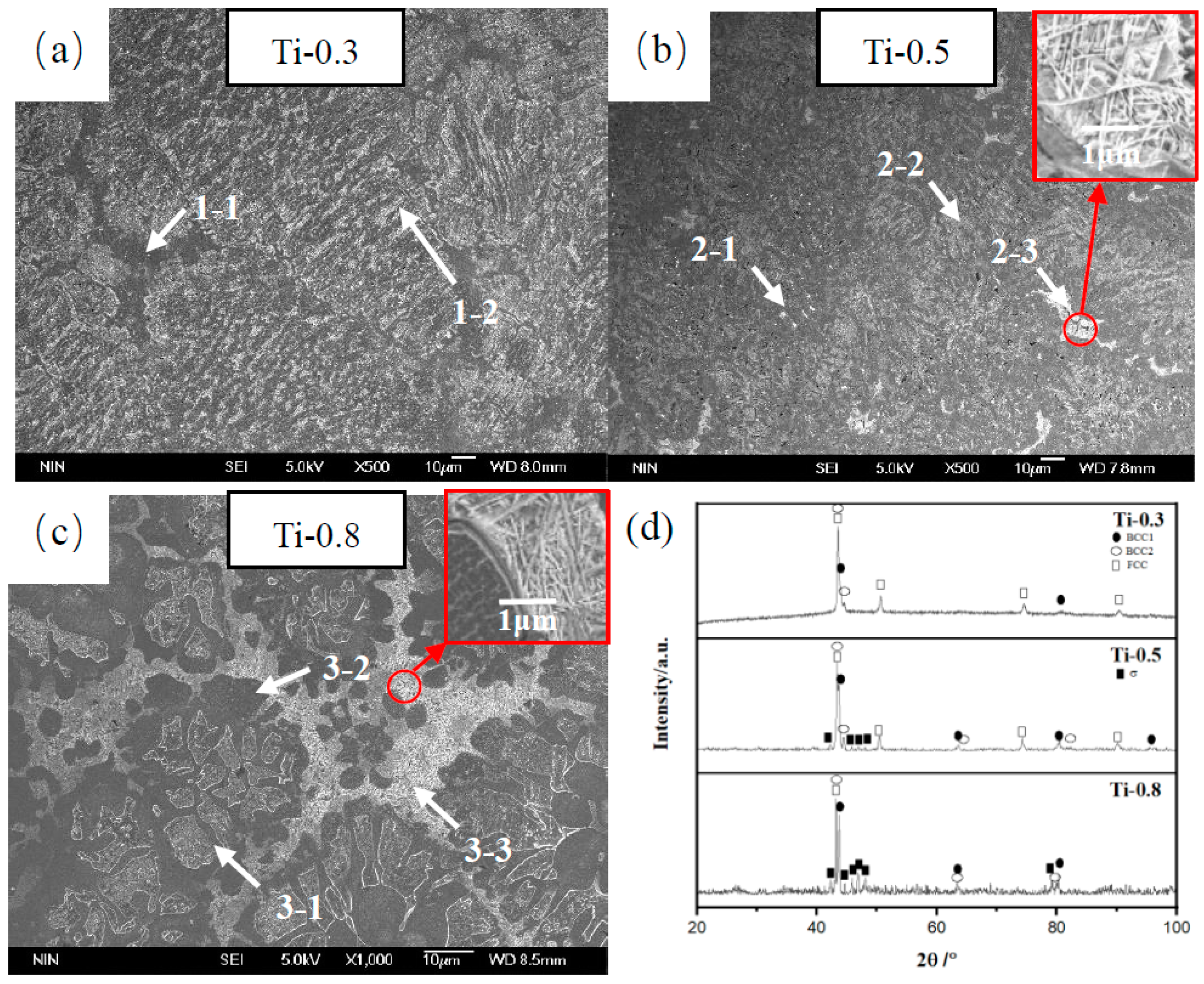
Figure 1 shows the microstructure and XRD patterns of the as-cast Al0.5CoCrFeNiTix HEAs. Based on the XRD results, the diffraction peak is narrow and sharp, indicating that the alloy exhibits high crystallinity. The intensity of the large angle diffraction peak is weak because the change in the atomic radius of multiple principal elements in the HEAs leads to lattice distortion and enhanced diffuse reflection, and the intensity of the diffraction peak decreases with increasing scanning angle.
Additionally, the Ti-0.3 alloy is mainly composed of the FCC phase and a small amount of the BCC phase. With increasing Ti content, the diffraction peak of BCC increases gradually. For alloy Ti-0.8, the diffraction peak intensity of the BCC phase is similar to the diffraction peak intensity of the FCC phase, indicating that the phase contents in the alloy are similar. The FCC phase is of the A1 type, with a = 3.5975 Å and the Pearson symbol of cF4. The BCC1 phase is of the A2 type, with a = 2.876 Å and the Pearson symbol of cl2. The BCC2 phase is of the B2 type, with a = 2.920 Å and a Pearson symbol of cP2. By comparing the XRD results of the three Al0.5CoCrFeNiTix HEAs, we found that the diffraction peak of the solid solution shifted slightly to the left with increasing Ti addition, indicating that the lattice parameters of the BCC phase increased slightly, and that lattice distortion occurred as more Ti with a large atomic radius dissolved into the BCC solid solution. Some previous studies have found the same phenomenon [24,25].
Based on the SEM results, Ti-0.3 and Ti-0.5 alloys are cellular structures. Inside the cell, the dark gray phase and light gray phase are arranged alternately. A dark gray phase was mainly observed between the cells. From the EDS results (Table 2), Co is distributed uniformly in the alloy. Al, Ti and Ni are enriched in light gray phases (Areas 1-2 and 2-2), while Fe and Cr are enriched in dark gray phases, which can be explained by the mixing enthalpy between elements. Table 3 shows that by comparing the mixing enthalpy between elements, the negative enthalpy of mixing between Al, Ni and Ti is lower. Thus, the metal binding force between AlTiNi is stronger, and the combination of these three elements forms the ordered BCC phase (AlNi2Ti). Cr and Fe are repelled from the light gray phases, which makes the dark gray phases rich in Cr and Fe. Many researchers have found element segregation in different phases in HEAs. Zhang et al. [26] added Al to a CoCrFeNiTi alloy and found that significant element segregation occurred in the alloy. The dendrite region is rich in Co, Ni, Ti and Al, while the interdendrite region is rich in Fe and Cr. Saideep et al. [21] found that the microstructure of AlCoCrFeNi2.1 consists of a lamellar arrangement of L12 and B2 solid-solution phases. The two phases have different elemental compositions. The B2 phase was found to be rich in Ni and Al, while the L12 phase was rich in Co, Cr, and Fe. The above studies are similar to the studies in this paper. According to XRD and EDS analysis of Ti-0.3 and Ti-0.5 alloys, it is reasonable to infer that the light gray and dark gray phases are BCC (A2/B2) and FCC solid solutions, respectively.
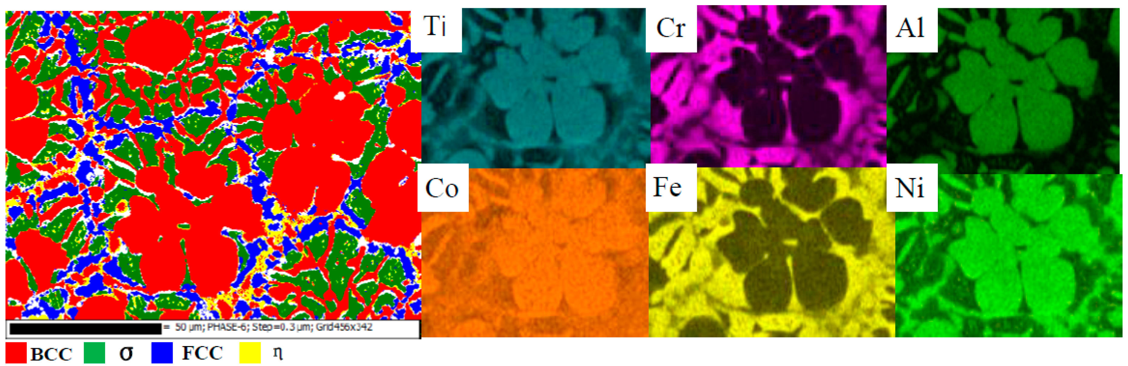
With increasing Ti content, intermetallic compound σ precipitates gradually precipitated in the high-entropy alloys. According to the XRD results, the σ phase had formed within the Ti-0.5 alloy, but it is difficult to observe them from SEM images due to the small amount. With a further increase in the Ti content, the FCC phase and BCC phase in the Ti-0.8 alloy decrease significantly, and a large amount of intermetallic compound σ precipitates. The σ phase (Cr0.99Fe1.01) has a tetragonal structure, with a = 8.797 Å, c = 4.558 Å and the Pearson symbol tP30. According to the electron backscatter diffraction (EBSD) results in Figure 2, the flower-like light gray phase is the BCC phase, which is rich in TiAlNi. Numerous σ phases are distributed in the gap between the BCC phases. The element distribution diagram shows that numerous Cr and Fe elements are enriched around the flower-like BCC phase. The content of Cr is up to 34.43%, almost twice the average content. A large amount of Cr contributes to the formation of the σ phase. In addition, Cr tends to decrease toward the cell wall. The mixing enthalpy of Cr and Fe with other elements is relatively high.
With the reduction of Cr, some acicular phase formed in the cell wall (Area 3-3). The same acicular phase is observed in the cell wall of the Ti-0.5 alloy (Area 2-3). The above two regions have high Ti and Ni contents, possibly due to the high mixing enthalpy between Ti and Ni, which easily combine to form intermetallic compounds. Wu et al. [24] also found this acicular phase when they studied FeCoCrAlNiTi1.5 and FeCoCrAlNiTi2 HEA coatings on 304 stainless steel. They considered this needle-like phase to be the (Ti, Ni) intermetallic compound phase. Thomas Lindner et al. [27] found that for the AlxCoCrFeNiTi alloy, a bright acicular phase precipitated between the cell wall when x = 0.2 and 0.8. They believed that the acicular phase was the intermetallic compound phase η with space Group P63/mmc (194) and hcp (D024) structures. However, they and Chuang et al. [28] found that the η phase could not be detected clearly by XRD analysis, consistent with the XRD results of this study, as it is difficult to observe the peak of this intermetallic compound phase.
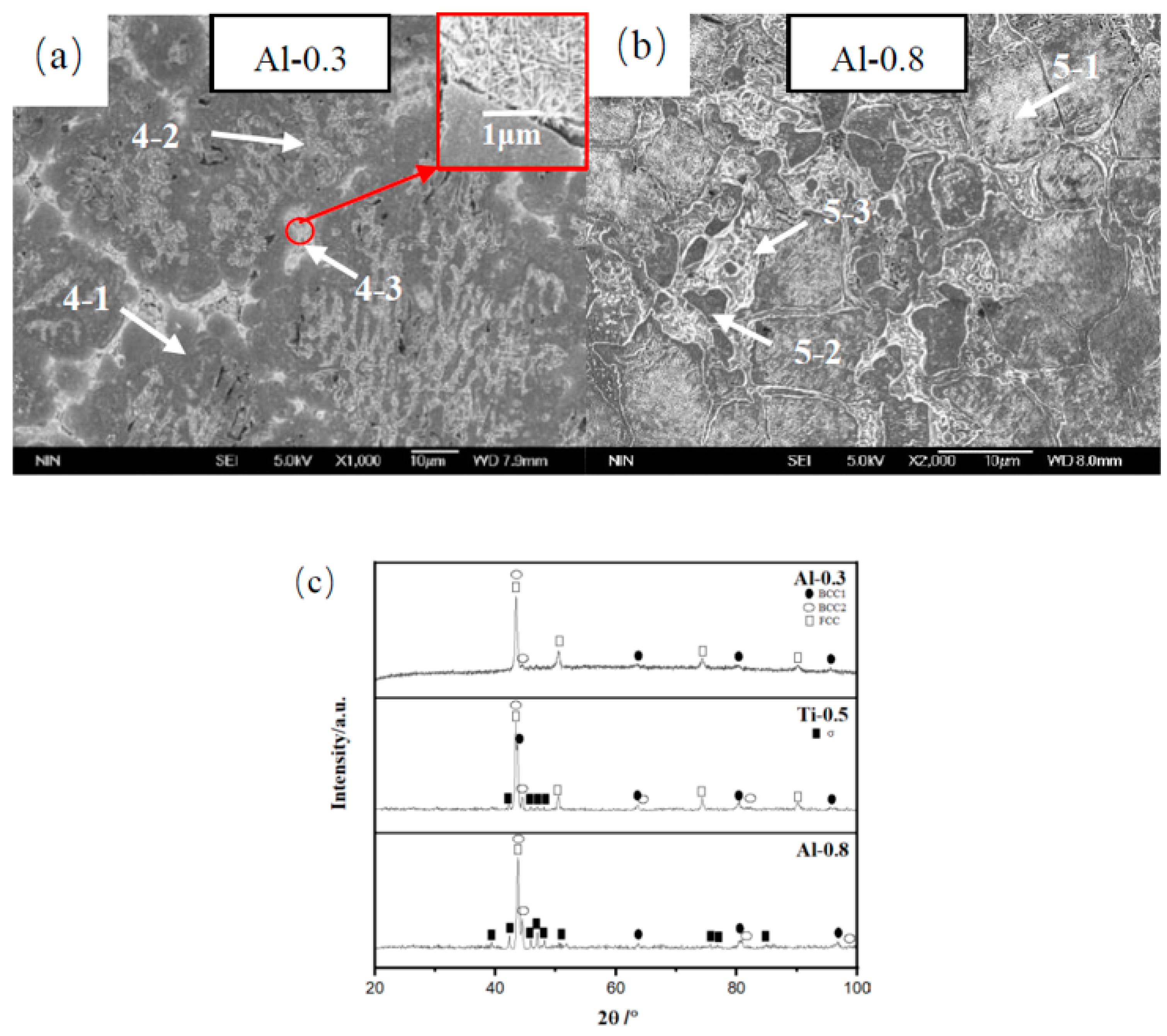
SEM and XRD results for the AlxCoCrFeNiTi0.5 HEAs are shown in Figure 3. The microstructure and phase composition of the Al-0.3 and Al-0.8 alloys are significantly different from the microstructure and phase composition of the Ti-0.5 alloy. The phase composition of the Al-0.3 alloy is relatively simple. The XRD results show that the phase composition contains an FCC phase and a small amount of BCC phase. However, we observed by SEM that acicular intermetallic compounds precipitate in the cell walls (Area 4-3). At present, only Ti-0.5, Ti-0.8 and Al-0.3 HEAs contain this phase among the 13 HEAs in this study. These three HEAs have a common characteristic, i.e., high Ti contents. The weight ratio of Ti in these HEAs ranges from 5.67 to 13.81 wt %, and the content of Ti in these three alloys ranges from 9.11 to 13.81 wt %, while the content of Ti in other alloys is less than 9 wt %.
Other studies [24,27,28] also found that in AlCoCrFeNiTi or CoCrFeNiTi HEAs, the acicular η phase, which is the (Ti, Ni) intermetallic compound phase, gradually precipitated in the AlCoCrFeNiTi HEAs with increasing Ti content. The acicular η phase can also be observed in many nickel-based superalloys [29,30,31], which was attributed to elemental segregation. Long et al. [31] calculated the partitioning coefficient of each element when studying nickel-based superalloys. If the partitioning coefficient of an element is greater than the unity, the element tends to segregate more in the dendrite core than in the liquid and vice versa. They found that Ti had a lower partition coefficient than that of other elements, so Ti has a strong segregation tendency to the liquid phase. As a result, the content of Ti in the interdendrite region of the nickel-based superalloy is higher, and it is easier to form the η phase with the main element Ni. In fact, in the solidification process of many multicomponent alloys, element segregation easily occurs. Some elements tend to segregate into the dendrite nuclei, while others tend to accumulate in the interdendrite. This results in micro-segregation of elements between dendrite and interdendrite regions. In this paper, the EDS results show that Ti-0.5, Ti-0.8 and Al-0.3 alloys also show similar element distributions. It can be inferred that when the three above HEAs solidify, the cell structure forms crystal nuclei, and Ti is segregated into the liquid phase. When the content of Ti is higher than the solution limit, Ti and Ni combine to form the (Ti, Ni)-rich intermetallic compound phase between cell walls. In addition, low Al content may be another factor influencing the formation of the η phase. Thomas Lindner et al. [27] believe that the Al content is also among the factors affecting the formation of the η phase. They found that with the further reduction of aluminum in the x = 0.2 alloy, the η phase precipitates. An increase in aluminum content prevents the the η phase from precipitating. The same phenomenon has been found in nickel-based superalloys. It has been reported that a high Ti/Al ratio favors the nucleation and growth of the η phase during solidification of superalloys [32,33].
The EDS results (Table 4) show that Al is enriched in the cell. The lattice constant of the FCC phase increases when Al is enriched inside the cell, and the alloy produces lattice distortion, leading to instability of the FCC phase. Since the atomic arrangement density of the BCC structure is lower than the atomic arrangement density of the FCC and HCP structures, it is easier to adapt the BCC structure to larger solute atoms. Therefore, adding too much Al will change the crystal structure of FCC to BCC and reduce the lattice distortion energy of the alloy. The BCC phase obviously increases with increasing Al content. When studying CoCrFeNiTiAlx HEAs, Zhang et al. [26] also found that the XRD pattern of the Al-1.0 alloy was similar to the diffraction pattern of the Al-0.5 alloy, but its reflected light shifted slightly to the left. The reflection shift can be attributed to the increase in the lattice constant caused by the solid solution of Al. As Al has a large atomic radius, the solid solution of Al will lead to lattice deformation and lattice expansion; thus, the lattice constant increases, and a reflection shift occurs [34]. Yu et al. [35] found that adding Al atoms can also slightly decrease the lattice parameters of FeNiCoCr HEA. This may be due to the distinct ionic size of aluminum atoms. In this paper, when the Al atom ratio reaches 0.8, numerous σ phases precipitate within the Al-0.8 alloy. In addition, the Al-0.8 alloy contains a small amount of FCC and BCC phases.
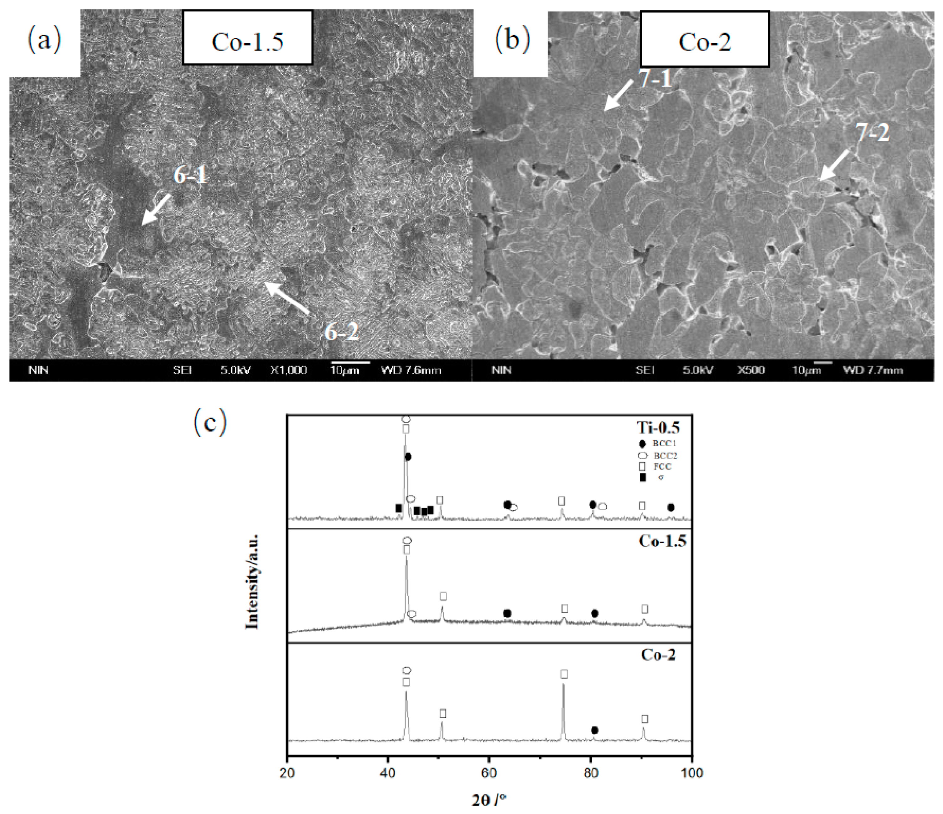
Figure 4 shows that the addition of Co can significantly change the phase composition and morphology of Al0.5CoxCrFeNiTi0.5 HEAs. The addition of Co makes the original BCC/FCC lamellar structure gradually disappear, and the microstructure gradually changes from a cellular structure to a dendritic structure. XRD analysis shows that both Co-1.5 and Co-2 alloys are composed of a large amount of the FCC phase and a small amount of the BCC phase. From the EDS results (Table 5), the overall element distribution of the Co-1.5 alloy is relatively uniform. The contents of Al and Ti in Area 6-2 are slightly higher, which may be due to the formation of a small amount of the BCC phase in this region. The Co-2 alloy shows the same distribution characteristics of elements. A small amount of BCC phase may form in the 7-2 region.
With increasing Cr content, the Cr-1.5 and Cr-2 alloys change from lamellae to equiaxed and flower-like structures (Figure 5). According to the SEM images at high magnification and low magnification (Figure 5a,b) of the Cr-1.5 alloy, lamellar structures are distributed around the equiaxed or flower-like phase, which are composed of an alternating white phase (8-2-W) and black phase (8-2-B). EDS analysis (Table 6) shows that the black phase is a high Cr phase, which can be inferred to be the σ phase. The white phase is low in Al and Ti and high in Fe and Cr, and Ni and Co are at the average level, which should be the FCC phase. The equiaxed and flower-like phase rich in AlTiNi is the BCC phase. The XRD results showed that the increase in Cr content promoted the precipitation of σ. With the increase in Cr content, the peak values of the BCC and FCC solid solution phases decreased significantly, while the peak values of the σ phase increased significantly. By comparing the mixing enthalpy of Cr and other elements, the absolute value of the mixing enthalpy of Cr and Fe was determined to be the smallest, which is −1. In theory, intermetallic compounds formed by CrFe easily precipitate, consistent with the EDS results.
Figure 6 shows the microstructure and XRD patterns of the as-cast Al0.5CoCrFexNiTi0.5 alloys. The microstructures of the Fe-1.5 and Fe-2 alloys are similar to the microstructure of the Ti-0.5 alloy, both of which are cellular structures. With increasing Fe content, the phase composition of the Al0.5CoCrFexNiTi0.5 alloys showed little change. However, the XRD peak value of the BCC phase decreases with increasing Fe content. The EDS results (Table 7) show that Co, Cr, Fe and Ni are enriched in the dark gray area (Areas 10-1 and 11-1) in the Fe-1.5 and Fe-2 alloys, which should be the FCC phase. Al and Ti are enriched in the light gray area (Areas 10-2 and 11-2), and they easily form the BCC phase when combined with Ni. The light gray area decreases with increasing Fe content, while the dark gray area increases, consistent with the XRD results.
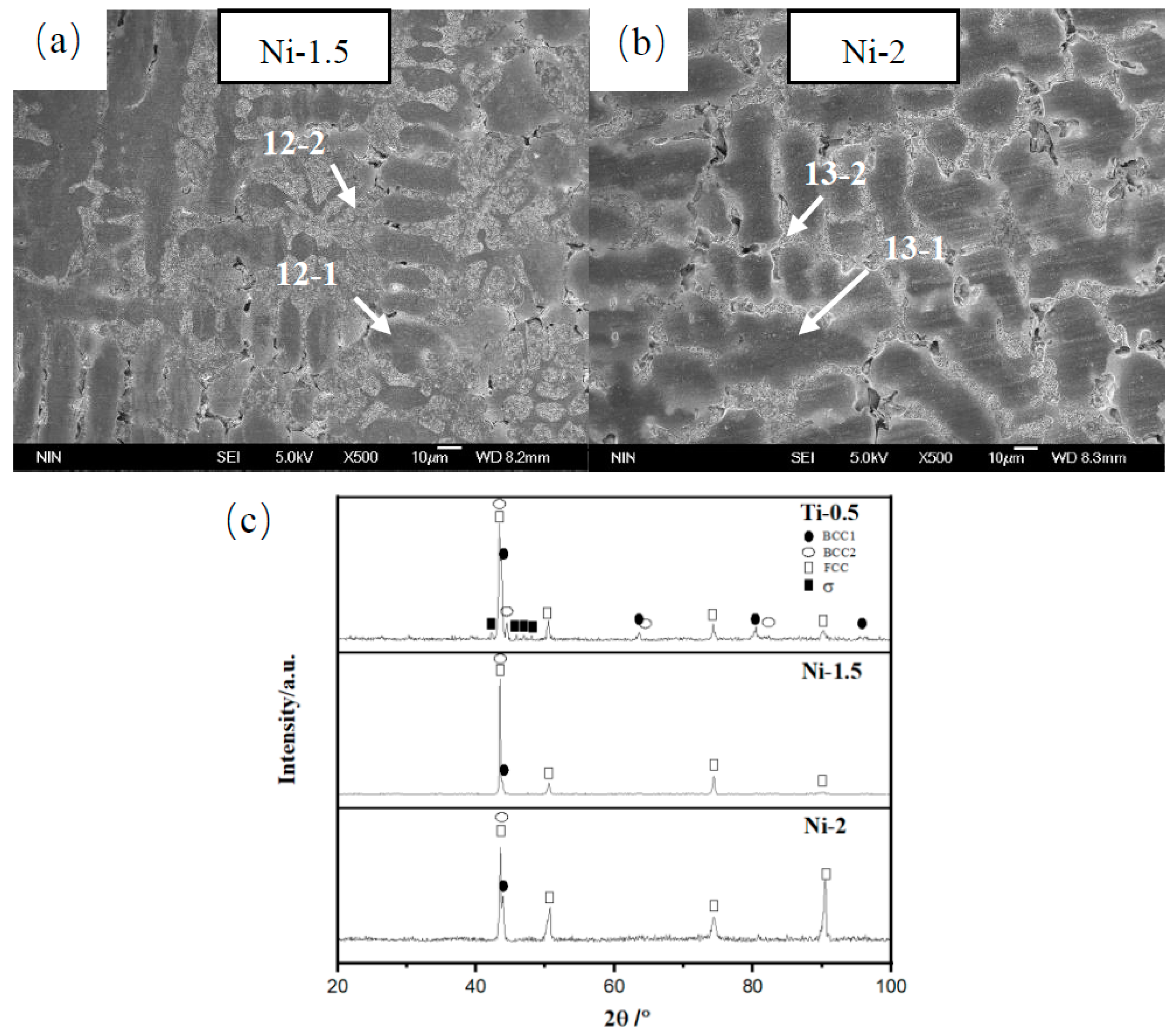
The XRD patterns and microstructure of AlCoCrFeNixTi alloys with Ni additions are shown in Figure 7. With the increase in Ni, the microstructure of Al0.5CoCrFeNixTi0.5 HEAs change significantly. The microstructure of Ti-0.5 is BCC/FCC lamellae distributed in the cell, while Ni-1.5 and Ni-2 alloys are typical dendrite structures. Moreover, the dendrite phase obviously coarsened with increasing Ni. The EDS results (Table 8) show that the dendrite phase (Areas 12-1 and 13-1) contains less Al and Ti but is enriched in Co, Cr, Fe and Ni, forming a typical FCC phase. The interdendritic area (Areas 12-2 and 13-2) is rich in Al, Ti and Ni, forming the BCC phase. Based on the XRD results, the peak value of the FCC phase with chemical composition FeNi is enhanced, indicating that the Ni element promoted the formation of the FCC phase.
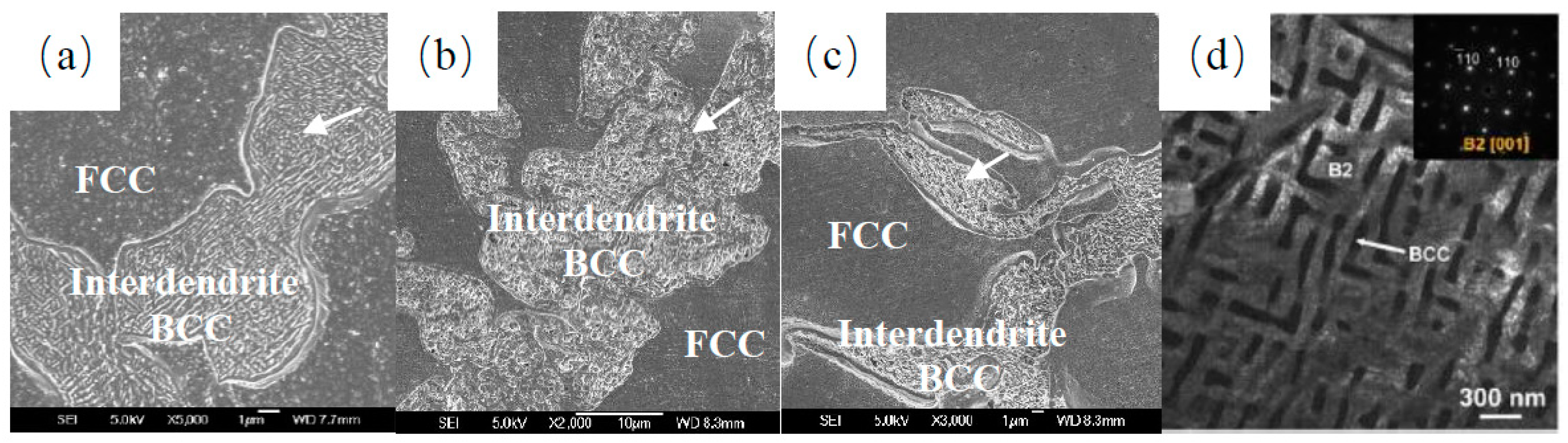
From the high-magnification SEM images (Figure 8a–c), some submicron microstructures can be found within the Co2, Ni1.5 and Ni2 alloys (indicated by arrows). All three alloys have typical dendrite structures. The dendrite phase is the FCC phase and the BCC phase. However, in the BCC phase, the distribution of the smile needle structure can be observed. Qiu et al. [36] analyzed the BCC phase of Al0.6CoCrFeNi alloy by the SAED pattern of TEM. As seen in the TEM figure (Figure 8d), the brighter phase is the B2 (ordered BCC) phase, while the darker phase is the BCC (disordered BCC) phase. The widths of both the BCC and B2 phases are approximately 100 nm. Lee et al. [37] also discovered this structure when studying the interdendrite bcc phase of Al0.5CoCrFe1.5NiTi0.5 alloy. They believed that this was a eutectic structure consisting of disordered BCC and ordered BCC phases.

3.2. Mechanical Properties of AlCoCrFeNiTi HEAs

Table 9 shows the compressive properties of AlCoCrFeNiTi HEAs. The Al-0.8, Ti-0.8, Cr-1.5 and Cr-2 alloys are brittle during compression without plastic deformation. The other HEAs exhibit high compressive strength, in which the fracture strength σmax can be over 2 GPa. Large amounts of Al, Ti and Cr make the alloy brittle, while Co, Fe and Ni enhance the plasticity of the alloy because the addition of appropriate Al and Ti changes the FCC phase into the BCC phase to improve the strength of the alloy, while excessive additions promote the precipitation of the brittle intermetallic compound phase. The presence of an intermetallic compound phase in the microstructure can significantly reduce the configurational entropy of adjacent solid solutions, thus reducing the strengthening effect of solid solutions [38,39]. Therefore, high-entropy alloys with intermetallic phases do not exhibit higher strength. Co, Fe and Ni change the alloy from a complex multiphase composition to a simple FCC structure and improve the plasticity of the alloy. The Ti-0.3, Fe-1.5, Fe-2 and Ni-2 alloys show good comprehensive properties and exhibit high plasticity and toughness. In particular, the fracture strength of the Ti-0.3 and Fe-1.5 alloys exceeded 2500 MPa. According to the test results, the fracture strength σmax of the FCC CoCrFeNi alloy can be significantly improved by adding Al and Ti or adjusting the content of Co, Cr, Fe and Ni. In addition, the HEAs with more FCC content exhibit lower yield strength σy. Based on the perspective of crystal structure, the CoCrFeNi alloy is a typical FCC HEA with excellent plasticity but low strength. The FCC structure has higher atomic packing efficiency. After adding Al and Ti with larger atomic radii, the formed solid solution undergoes a solid solution, which will lead to lattice deformation and lattice expansion, thus significantly increasing the lattice constant and lattice distortion energy. This makes the high entropy alloy solid solution strengthening effect [25], with its strength greatly increased, and the plasticity slightly decreased.
The properties of AlCoCrFeNiTi HEAs are plotted in order of fracture strain from low to high, as shown in Figure 9. The properties of HEAs are closely related to the phase composition and morphology. When AlCoCrFeNiTi HEAs contain the σ phase, some of them break at the elastic stage, showing a typical brittle fracture. When HEAs are composed of a solid solution phase and acicular η phase, HEAs exhibit slight plasticity, and their strength ranges from 2000 to 2200 MPa. When HEAs consist only of FCC and BCC phases, their ductility and strength are greatly improved. In particular, the HEAs with cellular FCC + BCC structures show the best plasticity with fracture strains exceeding 0.4. However, if the acicular brittle phase precipitates in the cell wall of the cellular FCC + BCC structure, the plasticity of HEAs will be reduced, and their strength will also not be improved. In addition, the higher volume fraction of the FCC phase and appropriate amount of BCC phase can significantly improve the ductility and strength of HEAs, both in the dendritic solid solution structure and cellular structure. In contrast to previous studies [40,41,42,43,44,45,46,47,48,49,50,51], the HEAs show higher strength than that of traditional high strength alloys (Figure 10). The strength of conventional titanium alloys and superalloys is approximately 1000–1600 MPa. The strength of TWIP steels is higher, approximately 1400–2100 MPa, but their plasticity is low. The strength of the HEAs in Figure 10 are between 1500 and 2900 MPa. By comparing the HEAs in the figure, it can also be seen that adding an appropriate amount of Al or Ti elements to the FCC matrix can significantly enhance the alloy strength, but excessively adding these two elements greatly reduces the plasticity of the alloy. By adjusting the content of each element, most of the AlCoCrFeNiTi HEAs in this paper show good strength and plasticity.
The SEM images of the fracture morphology of the AlCoCrFeNiTi HEAs are shown in Figure 11. The fracture surfaces of AlCoCrFeNiTi HEAs are relatively smooth, and there are numerous stepped patterns at the fracture, which should be attributed to cleavage fracture. However, according to the compression performances, compared with other brittle materials, most of the HEAs have some plastic deformation at the initial stage of compression. Especially for the HEAs with high compressive strain, the mixed cracking mode of dimple and texture can be observed at the fracture surface (Figure 11g,h).

3.3. Deformation Mechanisms of AlCoCrFeNiTi HEAs

According to the above analysis, the complex phase composition of AlCoCrFeNiTi HEAs has a direct effect on their mechanical properties. However, the influence of the microstructure on the mechanical properties cannot be obtained only through fracture morphology analysis. In this study, the deformation behavior of AlCoCrFeNiTi HEAs with different microstructures was studied, and the effect of the microstructure on crack initiation and propagation was observed. Due to the complex phase composition, large phase size and low intermetallic compound phase content of AlCoCrFeNiTi HEAs, we did not adopt transmission electron microscopy with a small observation area but rather observed the deformed samples by SEM to analyze the mechanical behavior of AlCoCrFeNiTi HEAs.
By observing the deformation samples of AlCoCrFeNiTi HEAs, more slip lines, including single slip and cross slip, can be observed in the FCC phase of the alloys regardless of the cell structure or dendrite structure. We can infer that the FCC phase bears the most deformation of the alloy. These dislocation motions carry a large amount of deformation in the alloy, providing plasticity for the material, and these dislocation rows are fixed to specific slip planes related to the short-range order in HEAs. When dislocation crosses the short-range ordered region of the slip plane, the distribution of solute atoms can be randomized, and the relative friction force of dislocation sliding on the specific slip plane can be reduced. At the initial stage of deformation, when the stress is low, a single slip system starts, but with the increase in deformation, multiple slip systems start. Faults in multiple directions begin to appear, and the extended width of these faults is very wide; as a result, intersections of faults in different slip systems are more likely to occur. These slip lines are also at an angle of 45–50° with the deformation direction.
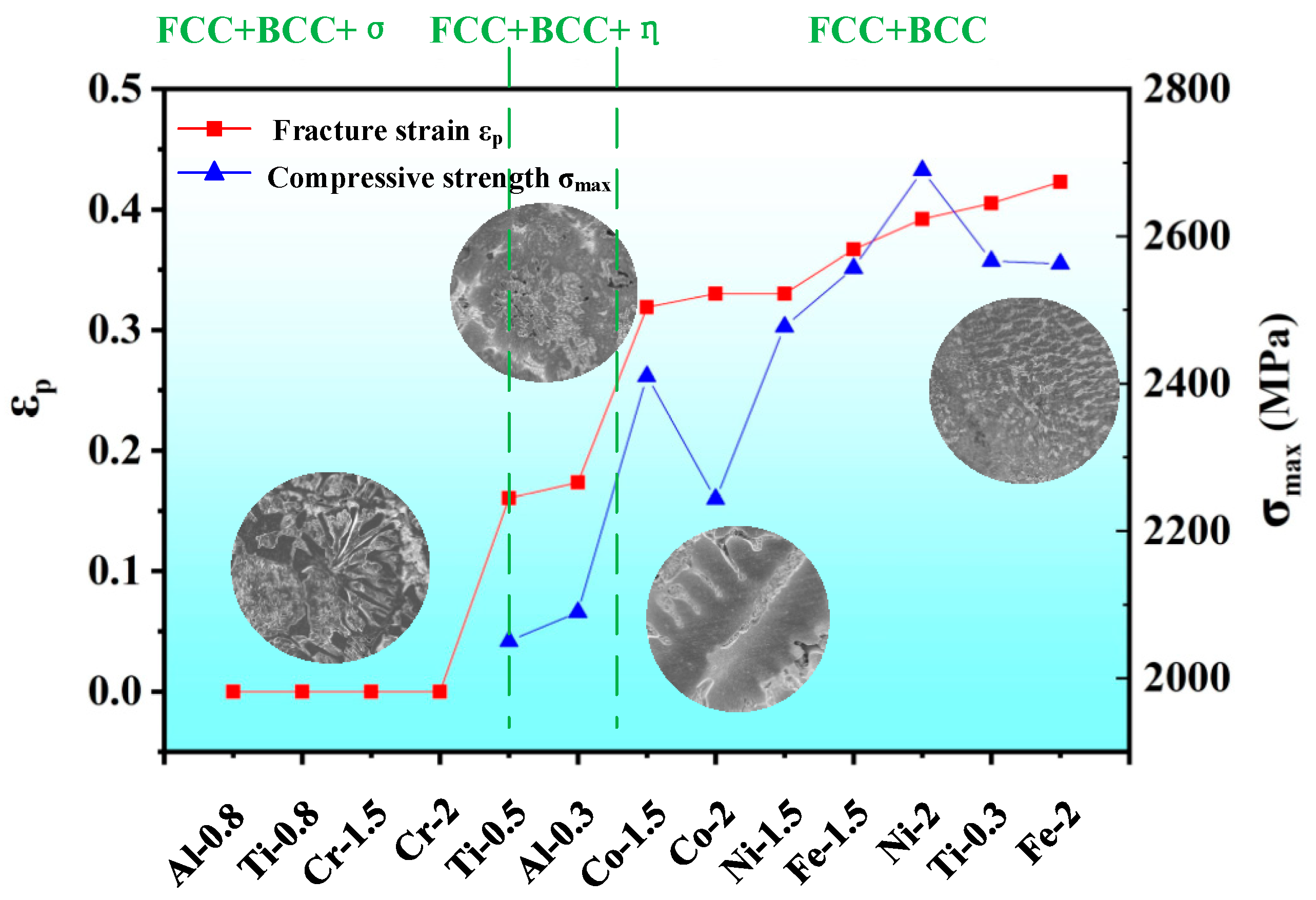
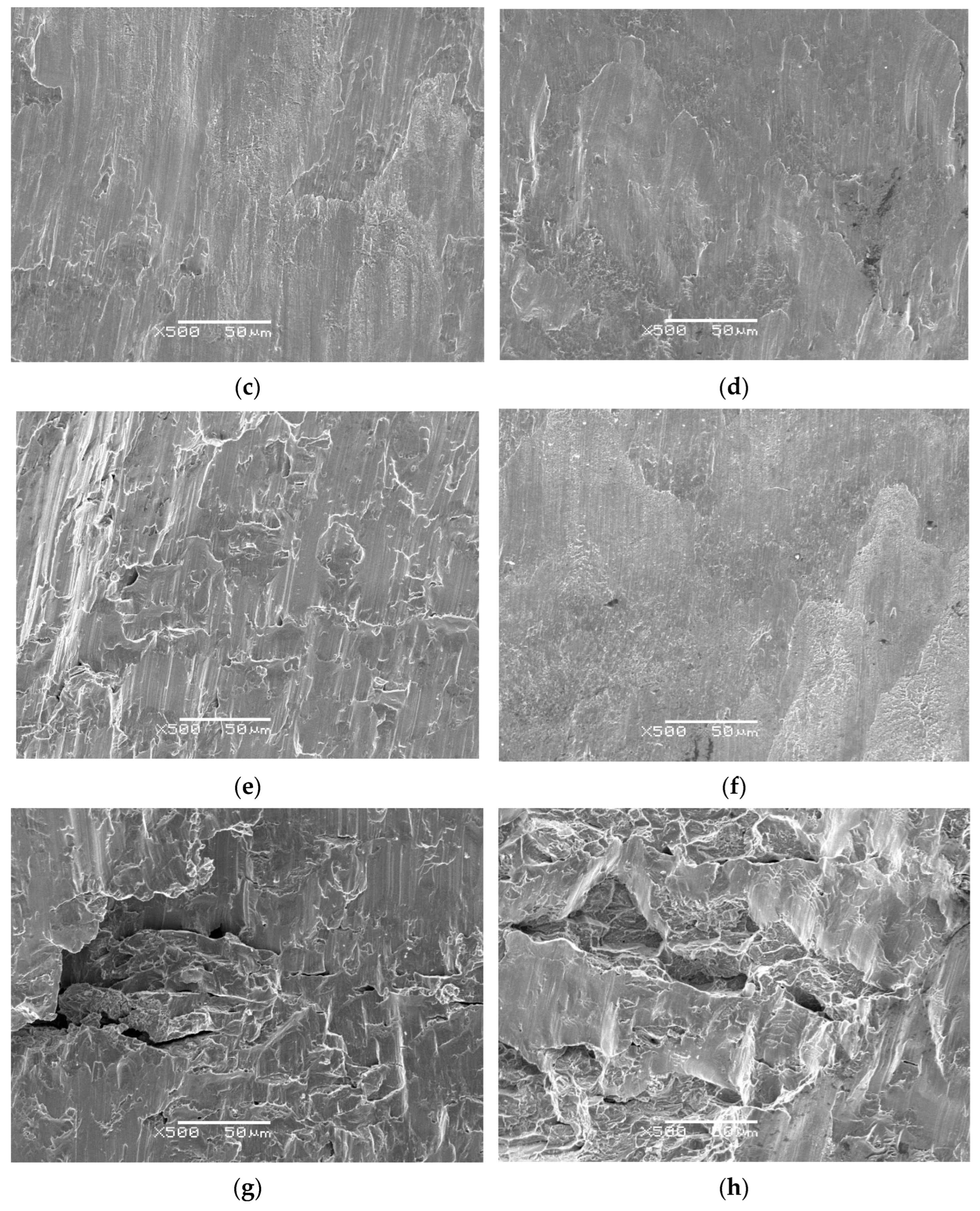
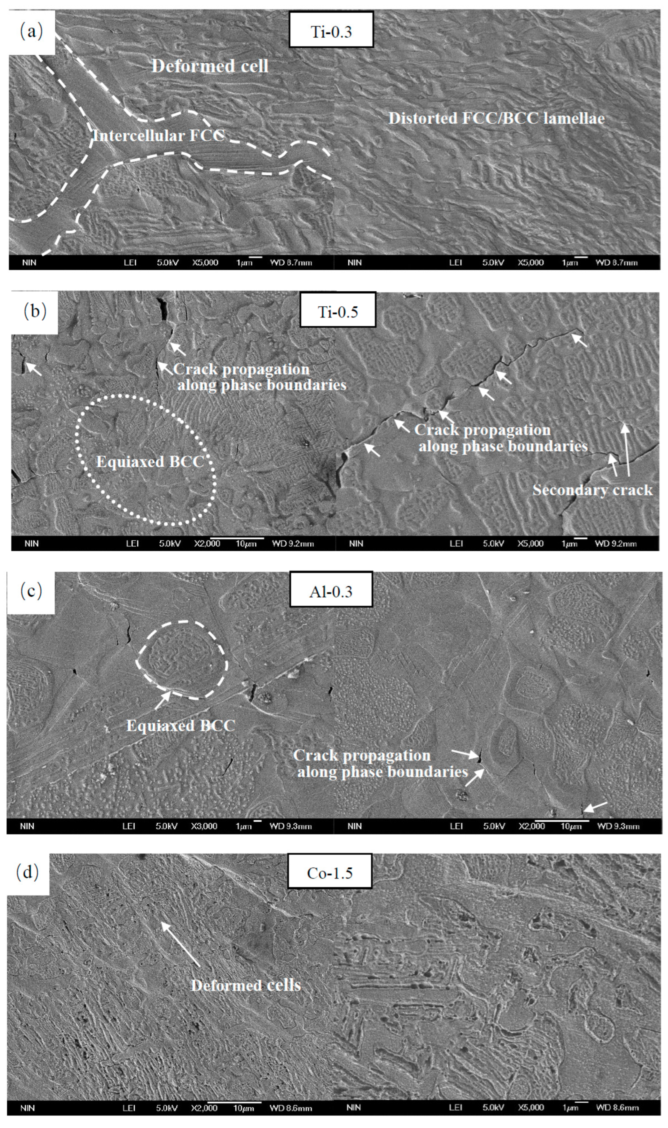
For the AlCoCrFeNiTi HEAs with cellular structures, if the alloy is only composed of a solid solution phase, such as Ti-0.3 (Figure 12a), Co-1.5 (Figure 12d), Fe-1.5 (Figure 12f) and Fe-2 (Figure 12g) alloys, the FCC/BCC lamellae are distributed alternately in the cell, and the BCC lamellae with higher strength are smaller. During deformation, in addition to the deformation of the intercellular FCC phase, the FCC/BCC lamellae in the cell were also distorted, and some slip lines across the lamellae could be observed in some areas (indicated by arrows in Figure 12g), showing that the deformation of FCC + BCC HEAs with cellular structures is uniform. Therefore, Ti-0.3, Co-1.5, Fe-1.5 and Fe-2 alloys exhibit great ductility. At the same time, the appropriate BCC phase also plays a strengthening role, so that the fracture strength of Ti-0.3 and Fe-2 alloys is above 2500 MPa.
Ti-0.5 (Figure 12b) and Al-0.3 (Figure 12c) alloys also have cellular structures, but from the high-magnification SEM, the shape and size of the BCC phase in the cell are greatly different from Ti-0.3, Co-1.5, Fe-1.5 and Fe-2 alloys. Ti-0.5 and Al-0.3 alloys contain numerous equiaxed BCC phases. According to the properties and microstructure, the structure of Ti-0.5 and Al-0.3 alloys is not conducive to uniform deformation of materials. The thin BCC/FCC lamella bends and distorts as a whole, but the equiaxed BCC or thick lamellar BCC/FCC does not easily bend under the action of an external force due to its large size. In addition to equiaxed BCC and thick lamellar BCC/FCC, Ti-0.5 and Al-0.3 alloys also contain intermetallic compound phases. Due to these difficult-to-deform phases, it easy for dislocations to plug up at the phase boundaries, resulting in local nonuniform deformation, which leads to cracks. The crack continues to propagate along the boundary of the least resistance, as indicated by the arrow in Figure 12b. Simultaneously, the primary crack expands to the secondary crack, and the secondary crack also expands along the phase boundary. Therefore, for Ti-0.5 and Al-0.3 alloys, due to the characteristics of the microstructure, the plasticity and strength are much lower than the plasticity and strength of Ti-0.3, Co-1.5, Fe-1.5 and Fe-2 alloys.
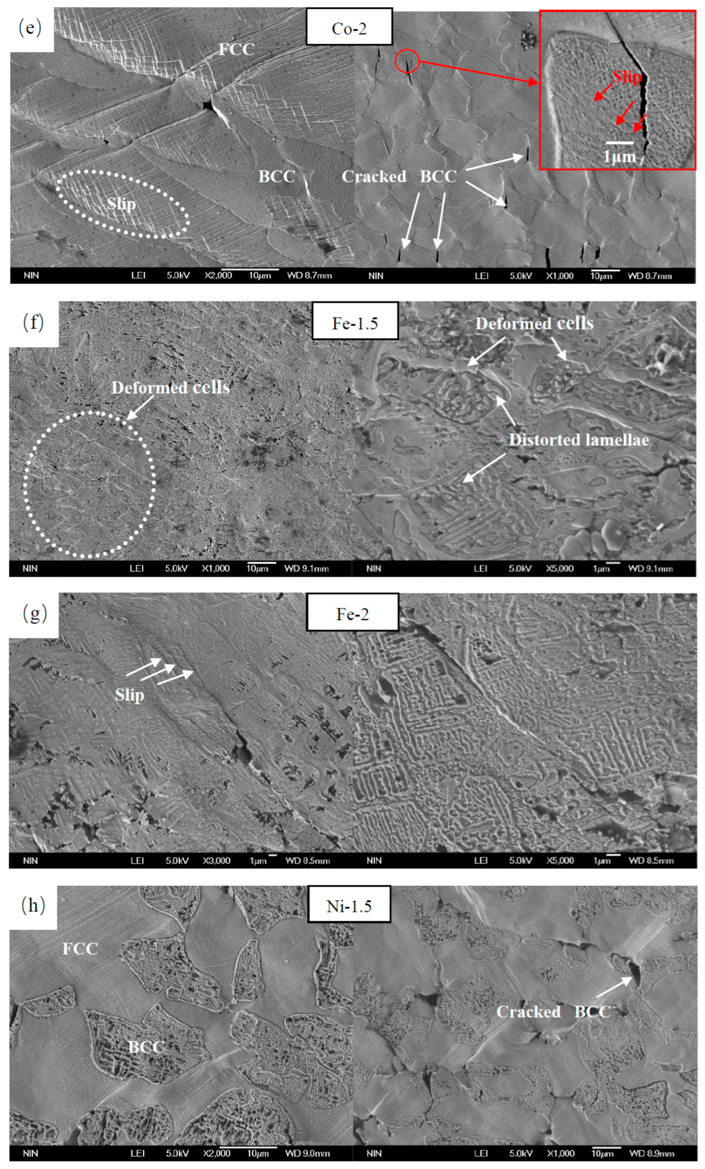
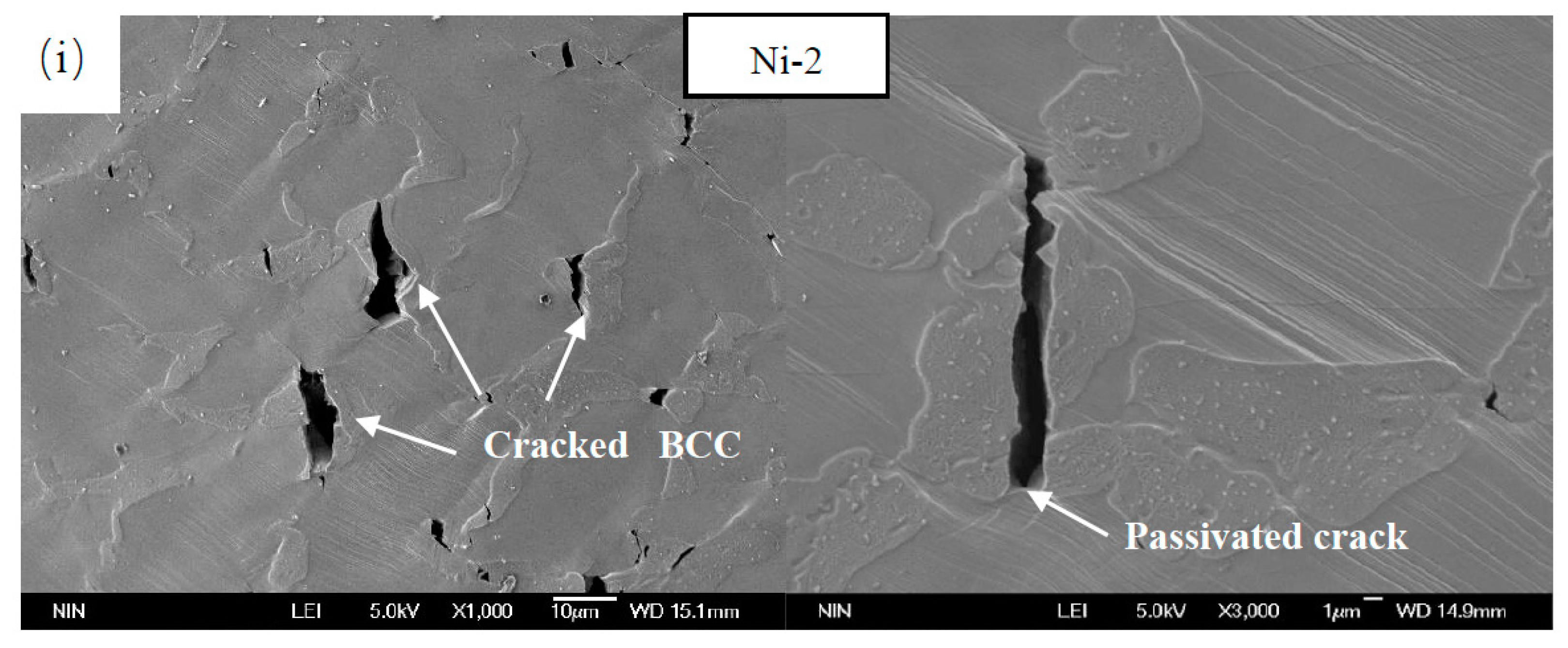
AlCoCrFeNiTi HEAs with dendrite structures, such as Co-2, Ni-1.5 and Ni-2 alloys, contain FCC dendrites and intergranular BCC phases. During deformation, cracks easily form at the boundary due to the large difference in the properties of the two phases. When the crack expands to the ductile phase FCC, the FCC encounters plastic deformation to relax the local stress and release the elastic energy, which hinders the formation and propagation of the crack. Compared with dendritic FCC, the interdendritic BCC phase has lower plasticity, so the critical stress needed for crack instability propagation in the BCC phase is relatively small. Cracks at the FCC/BCC boundary are more likely to propagate inward to the BCC. Figure 12e,h,i show that most cracks formed in the BCC phase are parallel to the direction of the external force. Some BCC phase cracks completely under the action of an external force. However, the crack passes when it extends to the FCC/BCC phase boundary. In addition, many short slip lines are observed in the BCC phase (inset of Figure 12e), indicating that the interdendritic BCC phase also yields and participates in plastic deformation.

4. Conclusions

(1)
The elements have a significant effect on the microstructure. With the addition of Ti, lattice distortion occurs as more Ti, with a large atomic radius, dissolves into the BCC solid solution. Al changes the crystal structure of FCC to BCC and reduces the lattice distortion energy of the alloy. The BCC phase obviously increases with increasing Al content. However, excessive Al, Ti and Cr promote the formation of intermetallic compound phases, while Ni, Fe and Co promote the transformation of AlCoCrFeNiTi HEAs into solid solutions. Compared with the Ti-0.5 alloy, the typical dendrite structure is changed by adding Co and Ni. When Ti exceeds 9 wt %, the acicular intermetallic compound phase is easily formed in the cell wall;
(2)
The properties of AlCoCrFeNiTi HEAs are closely related to their phase composition and morphology. When the HEAs contain the σ phase, they exhibit typical brittle fracture, and almost no plastic deformation occurs. When HEAs are composed of a solid solution phase and acicular intermetallic compound phase, they exhibit slight plasticity, and their strength ranges from 2000 to 2200 MPa. When HEAs consist only of FCC and BCC phases, their ductility and strength are greatly improved.
(3)
The AlCoCrFeNiTi HEAs with different microstructures show different deformation mechanisms. The deformation of FCC + BCC HEAs with cellular structures is uniform and presents great plasticity and strength. When the cellular-structure HEAs contain equiaxed BCC, thick lamellar BCC/FCC or intermetallic compound phases, cracks tend to occur and propagate along the phase boundary due to the local nonuniform deformation. For AlCoCrFeNiTi HEAs with dendrite structures, after initiation at the phase boundary, the crack does not easily spread to the dendrite FCC phase but causes the interdendritic BCC phase to crack.

Author Contributions

Experimental design, manuscript wrting, paper finalization, J.Z.; Revise manuscript, S.X.; Data acquisition, Y.Z. and C.Q.; Data analysis, J.Z. and P.G.; Language polishing, H.S.; Data interpretation, T.L. All authors have read and agreed to the published version of the manuscript.

Funding

The work was supported by Natural Science Basic Research Project of Shaanxi Province (Grant Nos. 2023-JC-QN-0507), Key Science and Technology Projects of Shaanxi Province (Grant Nos. 2020ZDLGY01-07 and 2019GY-162), and Science and Technology Projects of Xi’an Weiyang District (Grant Nos. 202109 and 202108).

Data Availability Statement

Not applicable.

Conflicts of Interest

The authors declare no conflict of interest.

References

  1. George, E.P.; Raabe, D.; Ritchie, R.O. High-entropy alloys. Nat. Rev. Mater. 2019, 4, 515–534. [Google Scholar] [CrossRef]
  2. Tsai, M.-H.; Yeh, J.-W. High-Entropy Alloys: A Critical Review. Mater. Res. Lett. 2014, 2, 107–123. [Google Scholar] [CrossRef]
  3. McAlpine, S.W.; Logan, J.V.; Short, M.P. Predicting single phase stability and segregation in the NbMoTaTi-(W,V) high entropy alloy system with the vacancy exchange potential. Scr. Mater. 2021, 191, 29–33. [Google Scholar] [CrossRef]
  4. Shahmir, H.; Asghari-Rad, P.; Mehranpour, M.S.; Forghani, F.; Kim, H.S.; Nili-Ahmadabadi, M. Evidence of FCC to HCP and BCC-martensitic transformations in a CoCrFeNiMn high-entropy alloy by severe plastic deformation. Mater. Sci. Eng. A Struct. Mater. Prop. Microstruct. Process. 2021, 807, 140875. [Google Scholar] [CrossRef]
  5. Yan, X.; Zhang, Y. Functional properties and promising applications of high entropy alloys. Scr. Mater. 2020, 187, 188–193. [Google Scholar] [CrossRef]
  6. Joseph, J.; Annasamy, M.; Kada, S.R.; Hodgson, P.D.; Barnett, M.R.; Fabijanic, D.M. Optimising the Al and Ti compositional window for the design of γ’ (L12)-strengthened Al–Co–Cr–Fe–Ni–Ti high entropy alloys. Mater. Sci. Eng. A 2022, 835, 142620. [Google Scholar] [CrossRef]
  7. Joseph, J.; Senadeera, M.; Chao, Q.; Shamlaye, K.; Rana, S.; Gupta, S.; Venkatesh, S.; Hodgson, P.; Barnett, M.; Fabijanic, D. Computational design of thermally stable and precipitation-hardened Al-Co-Cr-Fe-Ni-Ti high entropy alloys. J. Alloys Compd. 2021, 888, 161496. [Google Scholar] [CrossRef]
  8. Hassan, M.A.; Ghayad, I.; Mohamed, A.; El-Nikhaily, A.E.; Elkady, O.A. Improvement ductility and corrosion resistance of CoCrFeNi and AlCoCrFeNi HEAs by electroless copper technique. J. Mater. Res. Technol. JMRT 2021, 13, 463–485. [Google Scholar] [CrossRef]
  9. Kireeva, I.V.; Chumlyakov, Y.I.; Saraeva, A.A.; Vyrodova, A.V.; Pobedennaya, Z.V.; Kuksgauzen, I.V.; Kuksgauzen, D.A. Mechanical Behavior of Differently Oriented (CoCrFeNi)94Ti2Al4 Single Crystals. Phys. Mesomech. 2021, 24, 633–641. [Google Scholar] [CrossRef]
  10. Liu, H.-C.; Tsai, C.-W. Effect of Ge addition on the microstructure, mechanical properties, and corrosion behavior of CoCrFeNi high-entropy alloys. Intermetallics 2021, 132, 107167. [Google Scholar] [CrossRef]
  11. Gao, X.; Wang, L.; Guo, N.; Luo, L.; Zhu, G.; Shi, C.; Su, Y.; Guo, J. Microstructure and mechanical properties of multi-phase reinforced Hf-Mo-Nb-Ti-Zr refractory high-entropy alloys. Int. J. Refract. Met. H 2022, 102, 105723. [Google Scholar] [CrossRef]
  12. Mukarram, M.; Mujahid, M.; Yaqoob, K. Design and development of CoCrFeNiTa eutectic high entropy alloys. J. Mater. Res. Technol. JMRT 2021, 10, 1243–1249. [Google Scholar] [CrossRef]
  13. Regenberg, M.; Hasemann, G.; Wilke, M.; Halle, T.; Krueger, M. Microstructure Evolution and Mechanical Properties of Refractory Mo-Nb-V-W-Ti High-Entropy Alloys. Metals 2020, 10, 1530. [Google Scholar] [CrossRef]
  14. Wei, S.; Kim, S.J.; Kang, J.; Zhang, Y.; Zhang, Y.; Furuhara, T.; Park, E.S.; Tasan, C.C. Natural-mixing guided design of refractory high-entropy alloys with as-cast tensile ductility. Nat. Mater. 2020, 19, 1175–1181. [Google Scholar] [CrossRef]
  15. Geng, Y.; Chen, J.; Tan, H.; Cheng, J.; Yang, J.; Liu, W. Vacuum tribological behaviors of CoCrFeNi high entropy alloy at elevated temperatures. Wear 2020, 456, 203368. [Google Scholar] [CrossRef]
  16. Qiu, S.; Zhang, X.-C.; Zhou, J.; Cao, S.; Yu, H.; Hu, Q.-M.; Sun, Z. Influence of lattice distortion on stacking fault energies of CoCrFeNi and Al-CoCrFeNi high entropy alloys. J. Alloys Compd. 2020, 846, 156321. [Google Scholar] [CrossRef]
  17. Wang, J.; Wu, S.; Fu, S.; Liu, S.; Yan, M.; Lai, Q.; Lan, S.; Hahn, H.; Feng, T. Ultrahigh hardness with exceptional thermal stability of a nanocrystalline CoCrFeNiMn high-entropy alloy prepared by inert gas condensation. Scr. Mater. 2020, 187, 335–339. [Google Scholar] [CrossRef]
  18. Wang, L.; Wu, X.Y.; Yao, C.L.; Shen, J.; Zhang, Y.P.; Ge, Y.H.; Zhang, G.J. Microstructural Stability of As-Cast and Directionally Solidified AlCoCrFeNi(2.1)Eutectic High-Entropy Alloys at Elevated Temperatures. Metall. Mater. Trans. Phys. Metall. Mater. Sci. 2020, 51, 5781–5789. [Google Scholar] [CrossRef]
  19. Muangtong, P.; Namus, R.M.; Goodall, R. Improved Tribocorrosion Resistance by Addition of Sn to CrFeCoNi High Entropy Alloy. Metals 2021, 11, 14. [Google Scholar] [CrossRef]
  20. Wu, Y.; Li, Z.; Feng, H.; He, S. Atomic Interactions and Order—Disorder Transition in FCC-Type FeCoNiAl1−xTix High-Entropy Alloys. Materials 2022, 15, 3992. [Google Scholar] [CrossRef]
  21. Saideep, M.; Vahid, H.; Riyadh, S.; Maryam, S.; Sundeep, M. Small-scale mechanical behavior of a eutectic high entropy alloy. Sci. Rep.-UK. 2020, 10, 2669. [Google Scholar]
  22. Xiao, D.H.; Zhou, P.F.; Wu, W.Q.; Diao, H.Y.; Gao, M.C.; Song, M.; Liaw, P.K. Microstructure, mechanical and corrosion behaviors of AlCoCuFeNi-(Cr,Ti) high entropy alloys. Mater. Des. 2017, 116, 438–447. [Google Scholar] [CrossRef] [Green Version]
  23. Boyat, X.; Ballat-Durand, D.; Marteau, J.; Bouvier, S.; Favergeon, J.; Orekhov, A.; Schryvers, D. Interfacial characteristics and cohesion mechanisms of linear friction welded dissimilar titanium alloys: Ti-5Al-2Sn-2Zr-4Mo-4Cr (Ti17) and Ti-6Al-2Sn-4Zr-2Mo (Ti6242). Mater. Charact. 2019, 158, 109942. [Google Scholar] [CrossRef]
  24. Wu, C.L.; Zhang, S.; Zhang, C.H.; Zhang, H.; Dong, S.Y. Phase evolution and cavitation erosion-corrosion behavior of FeCoCrAlNiTix high entropy alloy coatings on 304 stainless steel by laser surface alloying. J. Alloys Compd. 2017, 698, 761–770. [Google Scholar] [CrossRef]
  25. Gu, Z.; Xi, S.; Sun, C. Microstructure and properties of laser cladding and CoCr2.5FeNi2Tix high-entropy alloy composite coatings. J. Alloys Compd. 2020, 819, 152986. [Google Scholar] [CrossRef]
  26. Zhang, K.B.; Fu, Z.Y.; Zhang, J.Y.; Wang, W.M.; Wang, H.; Wang, Y.C.; Zhang, Q.J.; Shi, J. Microstructure and mechanical properties of CoCrFeNiTiAlx high-entropy alloys. Mater. Sci. Eng. A 2009, 508, 214–219. [Google Scholar] [CrossRef]
  27. Lindner, T.; Löbel, M.; Mehner, T.; Dietrich, D.; Lampke, T. The Phase Composition and Microstructure of AlxCoCrFeNiTi Alloys for the Development of High-Entropy Alloy Systems. Metals 2017, 7, 162. [Google Scholar] [CrossRef] [Green Version]
  28. Chuang, M.-H.; Tsai, M.-H.; Wang, W.-R.; Lin, S.-J.; Yeh, J.-W. Microstructure and wear behavior of AlxCo1.5CrFeNi1.5Tiy high-entropy alloys. Acta Mater. 2011, 59, 6308–6317. [Google Scholar] [CrossRef]
  29. Sharma, J.; Nicolaÿ, A.; De Graef, M.; Bozzolo, N. Phase discrimination between δ and η phases in the new nickel-based superalloy VDM Alloy 780 using EBSD. Mater. Charact. 2021, 176, 111105. [Google Scholar] [CrossRef]
  30. Liu, G.; Xiao, X.; Véron, M.; Birosca, S. The nucleation and growth of η phase in nickel-based superalloy during long-term thermal exposure. Acta Mater. 2020, 185, 493–506. [Google Scholar] [CrossRef]
  31. Long, F.; Yoo, Y.S.; Jo, C.Y.; Seo, S.M.; Jeong, H.W.; Song, Y.S.; Jin, T.; Hu, Z.Q. Phase transformation of η and σ phases in an experimental nickel-based superalloy. J. Alloys Compd. 2021, 478, 181–187. [Google Scholar] [CrossRef]
  32. Sun, W.; Lee, J.; Seo, S.; Choe, S.; Hu, Z. Relationship between η phase formation and solidification rate in directionally solidified IN792 + Hf alloy. Mater. Sci. Technol. 1999, 15, 1221–1224. [Google Scholar] [CrossRef]
  33. Seo, S.M.; Kim, I.S.; Lee, J.H.; Jo, C.Y.; Miyahara, H.; Ogi, K. Eta phase and boride formation in directionally solidified ni-base superalloy IN792 + Hf. Metall. Mater. Trans. A Phys. Metall. Mater. Sci. 2007, 38, 883–893. [Google Scholar] [CrossRef]
  34. Pearson, W.B.; George, H.V. A Handbook of Lattice Spacings and Structures of Metals and Alloys. Phys. Today 1959, 7, 528. [Google Scholar] [CrossRef]
  35. Yu, P.; Zhuang, Y.; Chou, J.P.; Wei, J.; Lo, Y.C.; Hu, A. The influence of dilute aluminum and molybdenum on stacking fault and twin formation in FeNiCoCr-based high entropy alloys based on density functional theory. Sci. Rep. 2019, 9, 10940. [Google Scholar] [CrossRef] [Green Version]
  36. Qiu, Y.; Thomas, S.; Fabijanic, D.; Barlow, A.J.; Fraser, H.L.; Birbilis, N. Microstructural evolution, electrochemical and corrosion properties of AlxCoCrFeNiTiy high entropy alloys. Mater. Des. 2019, 170, 107698. [Google Scholar] [CrossRef]
  37. Lee, C.F.; Shun, T.T. Effect of Fe content on microstructure and mechanical properties of Al0.5CoCrFexNiTi0.5 high-entropy alloys. Mater. Charact. 2016, 114, 179–184. [Google Scholar] [CrossRef]
  38. Moravcik, I.; Cizek, J.; Zapletal, J.; Kovacova, Z.; Vesely, J.; Minarik, P.; Kitzmantel, M.; Neubauer, E.; Dlouhy, I. Microstructure and mechanical properties of Ni1,5Co1,5CrFeTi0,5 high entropy alloy fabricated by mechanical alloying and spark plasma sintering. Mater. Des. 2017, 119, 141–150. [Google Scholar] [CrossRef]
  39. Tsai, K.Y.; Tsai, M.H.; Yeh, J.W. Sluggish diffusion in Co–Cr–Fe–Mn–Ni high-entropy alloys. Acta Mater. 2013, 61, 4887–4897. [Google Scholar] [CrossRef]
  40. Fu, Z.; Chen, W.; Fang, S.; Zhang, D.; Xiao, H.; Zhu, D. Alloying behavior and deformation twinning in a CoNiFeCrAl0.6Ti0.4 high entropy alloy processed by spark plasma sintering. J. Alloys Compd. 2013, 553, 316–323. [Google Scholar] [CrossRef]
  41. Zhou, Y.J.; Zhang, Y.; Wang, Y.L.; Chen, G.L. Solid solution alloys of AlCoCrFeNiTix with excellent room-temperature mechanical properties. Appl. Phys. Lett. 2007, 90, 181904. [Google Scholar] [CrossRef]
  42. Shun, T.-T.; Chang, L.-Y.; Shiu, M.-H. Microstructures and mechanical properties of multiprincipal component CoCrFeNiTix alloys. Mater. Sci. Eng. A 2012, 556, 170–174. [Google Scholar] [CrossRef]
  43. Tong, Y.; Chen, D.; Han, B.; Wang, J.; Feng, R.; Yang, T.; Zhao, C.; Zhao, Y.; Guo, W.; Shimizu, Y.; et al. Outstanding tensile properties of a precipitation-strengthened FeCoNiCrTi0.2 high-entropy alloy at room and cryogenic temperatures. Acta Mater. 2019, 165, 228–240. [Google Scholar] [CrossRef]
  44. Li, C.-L.; Hong, J.-K.; Narayana, P.L.; Choi, S.-W.; Lee, S.W.; Park, C.H.; Yeom, J.-T.; Mei, Q. Realizing superior ductility of selective laser melted Ti-6Al-4V through a multi-step heat treatment. Mater. Sci. Eng. Struct. Mater. Prop. Microstruct. Process. 2021, 799, 140367. [Google Scholar] [CrossRef]
  45. Xu, S.H.; Zhou, C.S.; Liu, Y.; Liu, B.; Li, K.Y. Microstructure and mechanical properties of Ti-15Mo-xTiC composites fabricated by in-situ reactive sintering and hot swaging. J. Alloys Compd. 2018, 738, 188–196. [Google Scholar] [CrossRef]
  46. Lu, J.; Ge, P.; Li, Q.; Zhang, W.; Huo, W.; Hu, J.; Zhang, Y.; Zhao, Y. Effect of microstructure characteristic on mechanical properties and corrosion behavior of new high strength Ti-1300 beta titanium alloy. J. Alloys Compd. 2017, 727, 1126–1135. [Google Scholar] [CrossRef]
  47. Li, D.; Qian, L.; Wei, C.; Liu, S.; Zhang, F.; Meng, J. The tensile properties and microstructure evolution of cold-rolled Fe–Mn–C TWIP steels with different carbon contents. Mater. Sci. Eng. A 2022, 839, 142862. [Google Scholar] [CrossRef]
  48. Kusakin, P.; Belyakov, A.; Haase, C.; Kaibyshev, R.; Molodov, D.A. Microstructure evolution and strengthening mechanisms of Fe–23Mn–0.3C–1.5Al TWIP steel during cold rolling. Mater. Sci. Eng. A 2014, 617, 52–60. [Google Scholar] [CrossRef]
  49. Liu, X.; Hu, R.; Luo, X.; Yang, C.; Gao, X. A high-strength Ni–Cr–W based superalloy prepared by laser powder bed fusion: Printability, microstructure and tensile properties. Mater. Sci. Eng. A 2022, 853, 143744. [Google Scholar] [CrossRef]
  50. He, Y.; Liu, X.; Xing, C.; Bian, Z.; Zhou, Q.; Wang, J.; Wang, H.; Li, J. Effect of long-term aging treatment on the tensile strength and ductility of GH 605 superalloy. Prog. Nat. Sci. Mater. Int. 2022, 32, 375–384. [Google Scholar] [CrossRef]
  51. Wang, X.; Ding, Y.; Yu, H.; Bi, Z.; Gao, Y.; Gan, B. High strength and ductility in a novel Ni-based superalloy with γ′ and nanotwins/stacking faults architectures. Mater. Sci. Eng. A 2022, 847, 143293. [Google Scholar] [CrossRef]
Figure 1. Microstructure and XRD results for Al0.5CoCrFeNiTix HEAs: (a) Ti-0.3 alloy, (b) Ti-0.5 alloy, (c) Ti-0.8 alloy, and (d) XRD results.
Metals 13 00178 g001
Figure 2. EBSD results of Ti-0.8 HEA.
Metals 13 00178 g002
Figure 3. Microstructure and XRD results for AlxCoCrFeNiTi0.5 HEAs: (a) Al-0.3 alloy, (b) Al-0.8 alloy; and (c) XRD results.
Metals 13 00178 g003
Figure 4. Microstructure and XRD results for Al0.5CoxCrFeNiTi0.5 HEAs: (a) Co-1.5 alloy, (b) Co-2 alloy; and (c) XRD results.
Metals 13 00178 g004
Figure 5. Microstructure and XRD results for Al0.5CoCrxFeNiTi0.5 HEAs: (a,b) Cr-1.5 alloy, (c) Cr-2 alloy; and (d) XRD results.
Metals 13 00178 g005
Figure 6. Microstructure and XRD results for Al0.5CoCrFexNiTi0.5 HEAs: (a) Fe-1.5 alloy, (b) Fe-2 alloy; and (c) XRD results.
Metals 13 00178 g006
Figure 7. Microstructure and XRD results for Al0.5CoCrFeNixTi0.5 HEAs: (a) Ni-1.5 alloy, (b) Ni-2 alloy; and (c) XRD results.
Metals 13 00178 g007
Figure 8. High-magnification SEM images of: (a) Co2; (b) Ni1.5 and (c) Ni2 alloys; and (d) TEM of the BCC phase of Al0.6CoCrFeNi alloy [36].
Metals 13 00178 g008
Figure 9. Performance curve of AlCoCrFeNiTi HEAs.
Metals 13 00178 g009
Figure 10. Ashby plot including properties of AlCoCrFeNiTi HEAs in this paper, CoNiFeCrAl0.6Ti0.4 [40], AlCoCrFeNi [41], AlCoCrFeNiTi1.5 [41], CoCrFeNiTi0.3 [42], FeCoNiCrTi0.2 [43], Ti alloys (TC4 [44], Ti-15Mo-4.5TiC [45] and Ti1300 [46]), TWIP steels (Fe–18Mn-1.0C [47] and Fe–23Mn–0.3C–1.5Al [48]), Superalloys (Ni–Cr–W [49], GH 605 [50] and Ni-20.0Co-16.5Cr-5.0 W-2.5Al-2.5Ti-2.5Nb-0.02C [51]).
Metals 13 00178 g010
Figure 11. Fracture morphology of AlCoCrFeNiTi HEAs: (a) Ti-0.3; (b) Ti0.5; (c) Al-0.3; (d) Co-1.5; (e) Co-2; (f) Fe-2; (g) Ni-1.5; and (h) Ni-2.
Metals 13 00178 g011aMetals 13 00178 g011b
Figure 12. Deformed AlCoCrFeNiTi HEAs: (a) Ti-0.3; (b) Ti-0.5; (c) Al-0.3; (d) Co-1.5; (e) Co-2; (f) Fe-1.5; (g) Fe-2; (h) Ni-1.5; and (i) Ni-2.
Metals 13 00178 g012aMetals 13 00178 g012bMetals 13 00178 g012c
Table 1. Elemental composition of AlCoCrFeNiTi HEAs.
No.Alloys (at %)AbbreviationNo.Alloys (at %)Abbreviation
1 Al0.5CoCrFeNiTi0.3Ti-0.38Al0.5CoCr1.5FeNiTi0.5Cr-1.5
2 Al0.5CoCrFeNiTi0.5Ti-0.59Al0.5CoCr2FeNiTi0.5Cr-2
3 Al0.5CoCrFeNiTi0.8Ti-0.810Al0.5CoCrFe1.5NiTi0.5Fe-1.5
4 Al0.3CoCrFeNiTi0.5Al-0.311Al0.5CoCrFe2NiTi0.5Fe-2
5 Al0.8CoCrFeNiTi0.5Al-0.812Al0.5CoCrFeNi1.5Ti0.5Ni-1.5
6 Al0.5Co1.5CrFeNiTi0.5Co-1.513Al0.5CoCrFeNi2Ti0.5Ni-2
7 Al0.5Co2CrFeNiTi0.5Co-2---
Table 2. EDS results for Al0.5CoCrFeNiTix HEAs.
AlloysAreasElements (at %)
AlTiCoCrFeNi
Ti-0.31-15.283.3420.5927.7025.5617.53
1-27.879.4920.3620.1519.6822.46
Total7.235.8720.4123.7022.7020.11
Ti-0.52-17.069.2719.3921.7022.7219.86
2-212.4510.1919.2118.8818.8820.38
2-34.8323.3223.3210.2513.5326.76
Total9.9910.9419.6719.5320.0419.83
Ti-0.83-118.6622.5120.675.738.4823.95
3-24.058.2814.9034.4325.7612.58
3-31.7419.4417.4112.8219.1529.44
Total9.1217.7818.4117.3417.4519.89
Table 3. Mixing enthalpy between AlCoCrFeNiTi.
Mixing Enthalpy (kJ/mol)AlCoCrFeNiTi
Al0−19−10−11−22−30
Co-0−4−10−28
Cr--0−1−7−7
Fe---0−2−17
Ni----0−35
Ti-----0
Table 4. EDS results for AlxCoCrFeNiTi0.5 HEAs.
AlloysAreasElements (at %)
AlTiCoCrFeNi
Al-0.34-13.128.0020.0224.6924.2019.97
4-25.067.2419.7025.2824.2318.48
4-35.1312.2220.2620.6420.6321.13
Total4.4310.7020.1622.0222.2820.41
Al-0.85-118.2920.3020.826.049.6024.95
5-214.7511.3019.0916.8116.9021.15
5-33.555.7917.7527.7529.8115.34
Total15.0811.9518.3516.9817.1520.49
Table 5. EDS results for Al0.5CoxCrFeNiTi0.5 HEAs.
AlloysAreasElements (at %)
AlTiCoCrFeNi
Co-1.56-14.326.1927.1323.5321.7317.10
6-27.687.1525.5222.8220.5116.33
Total6.9010.0425.9820.6418.7317.71
Co-27-15.725.3432.5321.8120.0414.58
7-212.3314.7730.7411.6912.4418.03
Total7.138.5631.6719.3617.0416.24
Table 6. EDS results for Al0.5CoCrxFeNiTi0.5 HEAs.
AlloysAreasElements (at %)
AlTiCoCrFeNi
Cr-1.58-119.3117.0318.969.708.6926.32
8-2-B2.405.5615.9240.2023.4512.47
8-2-W6.056.2117.8826.8023.6119.45
Total9.8512.9318.8421.7416.0420.96
Cr-29-119.4019.8718.717.986.5327.50
9-2-B2.565.8315.5941.2321.1413.64
9-2-W15.5111.3816.0725.3611.3220.36
Total8.829.2616.0434.1315.5916.18
Table 7. EDS results for Al0.5CoCrFexNiTi0.5 HEAs.
AlloysAreasElements (at %)
AlTiCoCrFeNi
Fe-1.510-19.5715.0719.0213.5521.4821.31
10-213.3312.4217.8014.8621.2920.30
Total7.619.2317.6019.6528.0417.87
Fe-211-15.145.2315.4920.2539.1914.70
11-27.067.4015.6718.6535.2915.93
Total6.138.2315.5719.1234.8416.11
Table 8. EDS results for Al0.5CoCrFeNixTi0.5 HEAs.
AlloysAreasElements (at %)
AlTiCoCrFeNi
Ni-1.512-12.629.3017.5824.2421.1525.11
12-211.3015.6016.9113.9513.2829.07
Total7.839.5217.1720.7818.7325.97
Ni-213-16.067.1216.1821.2318.7630.65
13-216.8313.0314.4210.2210.9534.54
Total7.039.0815.9618.8317.2131.89
Table 9. Mechanical properties of AlCoCrFeNiTi HEAs.
No.Alloyσy (MPa)σmax (MPa)εp
1Ti-0.3720.212566.480.405
2Ti-0.51290.742050.510.1604
3Ti-0.8---
4Al-0.3955.432089.410.1736
5Al-0.8---
6Co-1.51088.712410.130.319
7Co-2496.252243.170.33
8Cr-1.5---
9Cr-2---
10Fe-1.51018.182556.630.367
11Fe-2931.092562.980.423
12Ni-1.5839.912477.420.33
13Ni-2819.532689.520.392
Disclaimer/Publisher’s Note: The statements, opinions and data contained in all publications are solely those of the individual author(s) and contributor(s) and not of MDPI and/or the editor(s). MDPI and/or the editor(s) disclaim responsibility for any injury to people or property resulting from any ideas, methods, instructions or products referred to in the content.

