Article

Machining Distortion for Thin-Walled Superalloy GH4169 Caused by Residual Stress and Manufacturing Sequences

1
School of Mechanical Engineering, Shandong University, Jinan 250061, China
2
Key Laboratory of High Efficiency and Clean Mechanical Manufacture of MQE, Key National Demonstration Center for Experimental Mechanical Engineering Education, Jinan 250061, China
*
Author to whom correspondence should be addressed.
Metals 2022, 12(9), 1460; https://doi.org/10.3390/met12091460
Submission received: 3 August 2022 / Revised: 21 August 2022 / Accepted: 28 August 2022 / Published: 31 August 2022
(This article belongs to the Special Issue Advanced Metal Cutting Technology and Tools)

Abstract

:
The residual stress generated in the machining process has a passive influence on the machining accuracy of a thin-walled workpiece. Annealing treatment can release the residual stress induced in the machining process and suppress the machining distortion. However, there is no unified standard for whether annealing treatment is arranged after machining. In this paper, an analytical model for predicting the distortion caused by residual stress of thin-walled superalloy GH4169 is established. Then, the finite element method is applied to analyze the prediction results of the proposed model. It is found that the residual stress generated in the manufacturing process chain can cause large distortion for the thin-walled workpiece. Finally, combined with the law and principle of workpiece distortion, the annealing process planning of multiple manufacturing sequences of thin-walled superalloy GH4169 is formulated to suppress the machining distortion. For the machining process on one side of the workpiece, it is necessary to release residual stress. This is not necessary for the double-sided machining process. Research results can be used to optimize the manufacturing sequence of thin-walled components.

1. Introduction

A superalloy has excellent comprehensive mechanical properties, but it increases the difficulty of machining and results in great residual stress on the machined surface [1,2]. The residual stress generated in the machining process has a passive influence on the machining accuracy for the thin-walled workpiece [3,4]. Although mechanical properties of superalloy material are perfect, their thin-walled parts can still deform under the influence of stress state [5]. For example, the diameter of large discs and shaft parts such as the turbine disc can reach 600 mm, and the thickness of the part wall is only 3 mm. Therefore, the heat treatment with annealing is usually arranged in the machining process to reduce residual stress and ensure the size and shape accuracy of the thin-walled parts.
Accurate prediction of machining distortion caused by machining residual stress is the prerequisite to prevent and control machining distortion of the thin-walled part. There are mainly theoretical models and finite element simulation methods to predict machining distortion of the thin-walled workpiece [6]. Meng et al. [7] measured residual stress on milling workpiece surface and depth of its affected layer by experimental means and predicted the bending distortion of workpiece caused by machining residual stress on the milling surface. The prediction result was in good agreement with experimental results. Zhang et al. [8] proposed a new method for calculating average residual stress of milling surface by simulation and experimental verification and established a prediction model for workpiece distortion caused by machining residual stress. The error between experimental result and simulation result was less than 20%. Wang et al. [9] established an analytical model based on elastic theory to predict the distortion of structural part. Then, the reliability of prediction results was verified by experiment and simulation, and the machining process was optimized according to the predicted result for control machining distortion. Masoudi et al. [10] studied the relationship between machining residual stress and machining distortion of the thin-walled part. The results showed that the increase of machining residual stress leads to the increase of workpiece distortion. Hussain et al. [11] established a simulation model to simulate machining distortion of complex structural parts and found that the error is small by experimental verification. Gao et al. [12] established a semi-analytical machining deformation prediction model based on equivalent bending stiffness of the workpiece, and the reliability of prediction results was verified by experiment and simulation. Weber et al. [13] analyzed the effect of the milling strategy for the thin-walled workpiece on machining distortion through finite element simulation. Three main categories of pre-control distortion compensation techniques were identified. Aurrekoetxea et al. [14] proposed a method for bulk stress characterization, which coupled the effects of bulk residual stresses, machining stresses resulting, and initial raw geometry. Their work results show that both bulk stress and machining stress affect the machining distortion of the workpiece.
In addition, Cerutti et al. [15] studied the influence of the initial residual stresses, the fixture layout, and the machining sequences on the machining quality. They reported that the fixture layout was important for its role in both the clamping and in the machining process. Therefore, an appropriate fixture layout was required to prevent workpiece deflections after clamping as well as during machining. Herranz et al. [16] studied the static and dynamic problems of the milling of low-rigidity parts to minimize the bending and vibration effects. They found that static problems were related to cutting forces while dynamic problems were related to vibrations. Therefore, the machine tool stiffness and machining parameters affected the machining accuracy of the thin-walled parts. In addition, the machining system including the workpiece, cutting tool, fixture, and the machine tool could be rigid to avoid vibration in the machining process. Annealing treatment is an effective method to reduce residual stress on machining surface and control machining distortion of the thin-walled workpiece. Zhu and Rahimi [17,18] conducted an experimental study found that annealing treatment can reduce residual stress of superalloy, and the greater residual stress can be decreased greatly. Landwehr et al. [19] machined a heat-treated workpiece and found that a low stress level can prevent machining deformation. Khan et al. [20] found that heat treatment can reduce workpiece machining deformation by 60%. However, parts have to go through several machining processes in the forming process. There is no definite standard for whether residual stress should be relieved by annealing after each machining process.
The objective of this paper is to formulate the process planning of annealing treatment and machining process for thin-walled superalloy GH4169. Firstly, the prediction model for thin-walled superalloy GH4169 bending distortion caused by machining residual stress is established based on a static equilibrium relationship. Then, the influence of residual stress on machining distortion of thin-walled superalloy GH4169 is analyzed by finite element simulation. Finally, the process planning of annealing treatment in multiple manufacturing sequences for thin-walled superalloy GH4169 is developed combining with the law and principle of workpiece distortion to suppress machining distortion. The novelty of the study is that an analytical model is proposed and is used to optimize the manufacturing sequences of a thin-walled workpiece, which is much simpler in comparison with the reference given.

2. Modelling of Machining Residual Stress Induced Distortion

Machining residual stress on a machined surface can be equivalent to the bending moment relative to the middle layer of the workpiece. The workpiece matrix will form a rival bending stress during its bending process. The residual stress on the machined surface is in balance with bending stress inside the workpiece when distortion is completed. Then, the curvature radius of distortional workpiece can be calculated to predict machining distortion by machining residual stress.

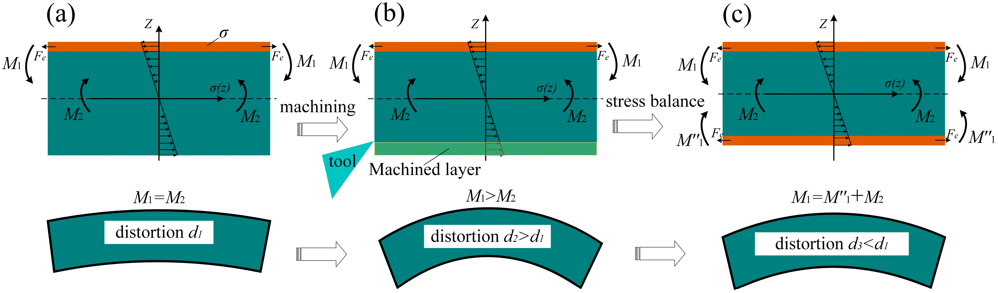
2.1. Equivalent Bending Moment

The residual stress generated in the machining process varies with depth after the thin-walled workpiece is machined. The residual stress in one direction of machined surface can be equivalent to the tension or pressure on the workpiece surface. Its equivalent unit force Fe can be calculated by Equation (1) [8]:
F e = σ ( h ) d h = σ a h e
where he (mm) is the depth of layer affected by residual stress, h (mm) is the depth of a point from surface, σ(h) (MPa) is residual stress of a point from a machined surface, σa (MPa) is the equivalent stress of the machined surface, and the width of the workpiece is assumed to be 1 mm.
Machining residual stress is equivalent to the force applied to the thin-walled workpiece and produces a bending moment M1 relative to the workpiece middle layer, and its expression is shown in Equation (2):
M 1 = H h e 2 b F e = 1 2 ( H h e ) h e b σ a
where H (mm) represents the thickness of the thin-walled workpiece, and b (mm) represents the width of the workpiece. The equivalent bending moment generated by residual stress is shown in Figure 1.

2.2. Bending Stress and Distortion of Machined the Thin-Walled Workpiece

Bending stress inside a distortional workpiece matrix is symmetrically distributed up and down when bending distortion occurs and the middle layer of the workpiece is a neutral layer with zero stress. However, machining residual stress will cause the neutral layer to deviate from the middle layer of workpiece [7]. The internal bending stress caused by workpiece distortion at the middle layer can be expressed as:
σ 0 = σ a h e H
According to Hooke’s law, the middle layer strain of distortional workpiece can be expressed as:
ε 0 = σ 0 E = σ a h e H E
where E is the elastic modulus.
Assuming that the curvature radius of distortional workpiece middle layer is R, the strain at any point inside workpiece is as follows:
ε ( z ) = 1 R z + ε 0
where z (−H/2 < z < H/2) (mm) represents the distance between the strain position and the middle layer.
According to Hooke’s law, the bending stress at any point inside distortional workpiece can be expressed as:
σ ( z ) = E ε ( z ) = E ( 1 R z + ε 0 )
The equivalent bending moment M2 is obtained by integral calculation of the bending stress inside distortional workpiece, as shown in Equation (7). The distribution of bending stress is shown in Figure 2:
M 2 = - H / 2 H / 2 σ ( z ) b z d z = - H / 2 H / 2 E ( 1 R z + ε 0 ) b z d z = E b H 3 12 R
The bending moment produced by machining residual stress is balanced during the distortion process of workpiece occurs after unloading in machining. The internal bending stress and machining residual stress reach a static equilibrium state when the distortion process is completed. According to the static equilibrium relation:
M 1 = M 2
Substituting Equations (2) and (7) into Equation (8), the relation between the curvature radius R of a distortional workpiece and the equivalent residual stress σa of machined surface can be obtained:
R = E H 3 6 ( H h e ) h e 1 σ a
Displacement of any point on the axis of distortion workpiece is defined as the distortion degree, expressed by dx, and its geometric relationship is shown in Figure 3. The distortion degree of workpiece can be expressed as:
d x = R ( cos α cos θ )
where θ is the central angle corresponding to the arc with half the length of the workpiece, and α is the central angle corresponding to the arc length between any point of the workpiece and the central line.
According to Figure 3, the maximum distortion degree of the bending workpiece is at the symmetric axis of workpiece, and its expression can be expressed as:
d max = R ( 1 cos θ ) θ = l 2 R
where l (mm) is the length of the workpiece. According to Equation (11), the workpiece distortion degree is related to residual stress and its depth, as well as the thickness and length of workpiece.

3. FEM Simulation of Thin-Walled Workpiece Bending Distortion

The finite element method is used to simulate and calculate the bending distortion of the thin-wall workpiece caused by surface residual stress. Firstly, the residual stress on the machined surface is obtained by cutting simulation. Then, the residual stress obtained by cutting simulation is imported to the surface of the thin-walled workpiece model. Finally, workpiece distortion occurs under an unconstrained state. The degree of workpiece distortion caused by residual stress is obtained after the distortion process is completed.

3.1. Orthogonal Cutting Simulation Modeling

The orthogonal cutting simulation model is established using Abaqus finite element software (Abaqus 2016, SIMULIA, Providence, RI, USA) to obtain the residual stress distribution on the machined surface of a superalloy thin-walled workpiece. The Jonson–Cook (J–C) material constitutive equation is used to characterize the plastic behavior of superalloy GH4169 in the cutting simulation model [21]. The constitutive parameters are shown in Table 1. In the simulation model, the tool front angle is 9°, the tool back angle is 6°, the radius of curvature of the cutting edge is 10 μm, the cutting depth is 0.1 mm, and the mesh size of workpiece is set at 10 μm. The length of the workpiece model is 3 mm, and the height is 2 mm. The bottom and sides of the workpiece are fixed, as shown in Figure 4. The cutting speeds are 60, 80, and 120 m/min, respectively.

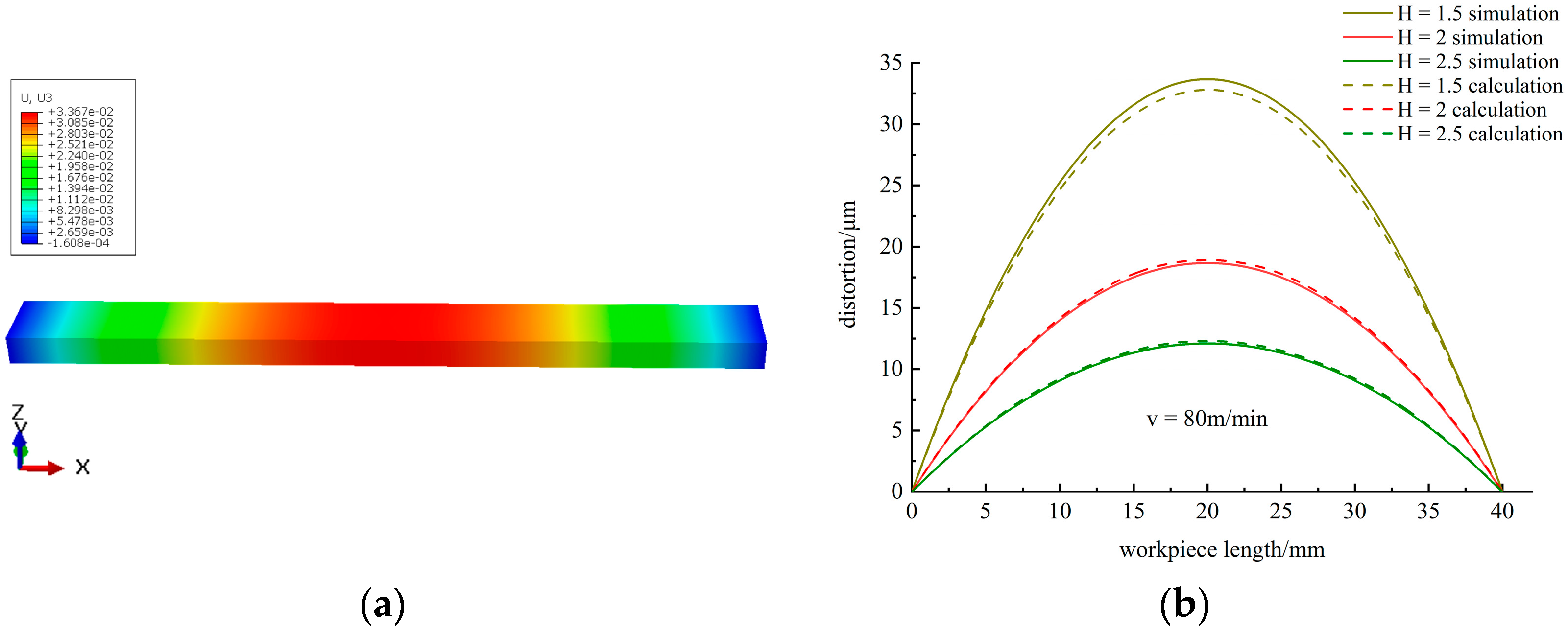
3.2. Bending Distortion Simulation

The rectangular thin-walled workpiece model was established in Abaqus finite element software to simulate and predict the bending distortion caused by machining residual stress. Residual stress data obtained by cutting simulation are imported into the surface of the thin-walled workpiece model. Then, workpiece distortion occurs under unconstrained state until static equilibrium, and the distortion degree is measured. The layer affected by residual stress is divided into seven thin plates with the thickness of 20 μm. Residual stress in each plate is the average of stress in this depth. These thin plates are in turn bound to the workpiece matrix. The distortion of the thin-walled workpiece is calculated in a “static, general” analysis step, and its CAE model is shown in Figure 5.
The length and width of the thin-walled workpiece model are 40 mm and 4 mm, respectively. The simulation cases and their parameters are shown in Table 2.

4. Results and Discussion

4.1. Orthogonal Cutting Simulation Modeling

The residual stress and its depth on the machined surface are key parameters to predict thin-walled workpiece distortion. The distribution of residual stress on the machined surface can be observed by cutting simulation results. The generation of residual stress is closely related to the cutting speed. The cutting simulation with different cutting speed conditions is carried out in order to obtain machining residual stress with obvious numerical difference. Consideration of only the residual stress in cutting direction and simulation results is shown in Figure 6.
The residual stress in the cutting direction on the topmost machined surface is tensile stress, and the subsurface is compressive stress. The maximum residual stress on the machined surface increase with the increase of cutting speed. The depth of residual stress affected layer in the simulation case is set at 140 μm and divided into seven layers on average. Residual stress in each layer is the average value of stress, as shown in Table 3.
The residual stress on the machined surface produces an equivalent bending moment relative to the middle layer of workpiece, which leads to the bending distortion. The distortional workpiece is arched because the equivalent residual stress on the machined surface is compressive stress.
The distortion degree of the workpiece is related to the residual stress on the machined surface, as shown in Figure 7. It can be seen from Figure 7 that the simulation results are consistent with the calculated results. The increase of machining residual stress results in the increase of an equivalent bending moment which causes distortion to occur. The maximum bending distortion degree of workpiece with a length of 40 mm and thickness of 2 mm is 15 μm, 18 μm, and 23 μm due to different residual stress conditions, respectively.
The thickness of workpiece affects its stiffness, which will decrease due to the reduction of thickness. The bending distortion degree of workpiece with different thickness under cutting speed of 80 m/min condition is shown in Figure 8. It can be seen from Figure 8 that the simulation results are consistent with the calculated results. The maximum bending distortion degree of thin-walled workpiece with different thickness is 12 μm, 18 μm, and 32 μm, respectively.
Therefore, it can be said that machining residual stress and workpiece thickness have a significant influence on the distortion of the thin-walled workpiece. Large residual stress and insufficient workpiece stiffness will lead to excessive distortion which affects the machining accuracy of the thin-walled workpiece.

4.2. Controlling to Suppress Distortion by Process Planning

The bending distortion caused by residual stress on the machined surface will affect the shape accuracy of the thin-walled workpiece, such as flatness and straightness beyond the tolerance range. Therefore, annealing treatment is usually arranged in the machining process to reduce residual stress. In addition, it is necessary to establish an exact criterion to determine whether the workpiece needs annealing treatment in multiple manufacturing sequences.
Superalloy thin-walled parts usually need to be machined several times in production, and machining allowance is left for later machining processes. However, the machining process destroys the stress balance inside the workpiece when the machined material is removed, which results in the distortion of the thin-walled workpiece, as shown in Figure 9.
In order to discuss the effect of multiple manufacturing sequences on machining distortion of a thin-walled workpiece more concisely and accurately, it is assumed that there is no residual stress inside the thin-walled workpiece without machining. Residual stress is generated on the workpiece surface which suffers the first machining process. Machining residual stress on the machined surface and bending stress inside the workpiece reach a static equilibrium state after the distortion is completed, as shown in Figure 9a. When the machining process is carried out again, the residual stress induced by the first machining process is released due to the removal of machining layer material. However, the bending stress inside the workpiece still exists, so the distortion will continue under the action of the bending stress due to an unbalanced state, as shown in Figure 9b. The residual stress induced by the second machining process is distributed on the machined surface and is in equilibrium with the bending stress through distortion, as shown in Figure 9c.
The rebalancing process of residual stress in multiple manufacturing sequences results in wave-like distortion of the thin-walled workpiece. According to the multiple machining distortion analysis, the final machining distortion of workpiece is related to the residual stress induced by the first machining process. If the distortion induced by residual stress of the first machining process is out of the tolerance range, the subsequent machining process shall be implemented after annealing treatment. If the residual stress induced by the second machining process is less than the first machining residual stress, the distortion caused by the first machining process does not exceed the tolerance range, the subsequent machining process will not lead to bigger distortion than the first machining, so the annealing treatment may not be arranged after the first machining process. If the residual stress induced by the second machining process is not less than the residual stress induced by first machining, the workpiece distortion will increase continually due to the decrease of the workpiece stiffness in the subsequent machining process, so the annealing treatment should be arranged to release the residual stress induced by the second machining process. The process planning of annealing treatment in multiple manufacturing sequences for the thin-walled workpiece is shown in Figure 10.
Some thin-walled parts require double-sided material removal during machining, such as turbine blades that need milling on both sides. The stress inside the workpiece is balanced after single-side machining, but a greater degree of distortion will occur due to the destruction of the stress balance when the reverse side of the workpiece is machined.
A certain degree of distortion occurs after the thin-walled workpiece without initial residual stress is machined on one side, and the residual stress on the machined surface is in equilibrium with the bending stress inside the workpiece, as shown in Figure 11a. The bending stress induced by the first machining distortion is reduced due to the removal of machining layer material when the reverse side of the thin-walled workpiece is machined. In addition, the distortion will increase under the action of residual stress induced by the first machining process, as shown in Figure 11b. After the workpiece is subjected to double-sided machining, the residual stress on two machined surfaces and bending stress inside workpiece reach a new balance, as shown in Figure 11c.
According to the above analysis, the final distortion degree of the thin-walled workpiece suffering double-side machining is still related to the residual stress induced by the first machining process. However, the subsequent machining distortion is offset by the residual stress generated on both sides when workpiece is subjected to the double-sided machining process. Even if the distortion induced by residual stress of first machining is excessive, the subsequent machining keeps the distortion within the tolerance range. Therefore, annealing treatment may not be arranged between double-side machining processes to release the residual stress induced by the first machining process.

5. Conclusions

In this paper, the analytical model is proposed to predict machining distortion of a thin-walled workpiece induced by machining residual stress. The influence of residual stress and the thickness of the thin-walled workpiece on machining distortion is analyzed by finite element simulation. The distortion behavior of the thin-walled workpiece in multiple manufacturing sequences is discussed and analyzed. Finally, the process planning of annealing treatment in the machining process for the thin-wall workpiece is put forward. The main conclusions are summarized as follows:
The residual stress generated in the machining process causes the distortion of the thin-walled workpiece. Large residual stress and insufficient workpiece stiffness will lead to excessive distortion of the thin-walled workpiece.
Multiple machining processes on one side of the thin-walled workpiece result in wave-like distortion. In addition, the final machining distortion of the workpiece is related to the residual stress induced by the first machining process. If the residual stress induced by the second machining process is less than the first machining residual stress, the subsequent machining process will not lead to bigger distortion than the first machining, so annealing treatment may not be arranged. If not, it is necessary to arrange annealing treatment to release residual stress.
The subsequent machining distortion is offset by the residual stress generated on both sides when the thin-walled workpiece is subjected to the double-sided machining process. Therefore, the annealing treatment may not be arranged between double-side machining processes.

Author Contributions

Conceptualization, Y.C.; methodology, Z.L.; validation, X.R.; investigation, P.Z.; resources, Y.C.; writing—original draft preparation, P.Z.; writing—review and editing, Z.L., X.R. and Y.C.; project administration, Z.L. All authors have read and agreed to the published version of the manuscript.

Funding

This research was funded by the National Natural Science Foundation of China (No. 91860207) and the National Key Research and Development Program of China (2019YFB2005401).

Institutional Review Board Statement

Not applicable.

Informed Consent Statement

Not applicable.

Data Availability Statement

The data presented in this study are available within the article.

Conflicts of Interest

The authors declare no conflict of interest. The funders had no role in the design of the study; in the collection, analyses, or interpretation of data; in the writing of the manuscript, or in the decision to publish the results.

References

  1. Madariaga, A.; Esnaola, J.A.; Fernandez, E.; Arrazola, P.J.; Garay, A.; Morel, F. Analysis of residual stress and work-hardened profiles on Inconel 718 when face turning with large-nose radius tools. Int. J. Adv. Manuf. Technol. 2014, 71, 1587–1598. [Google Scholar] [CrossRef]
  2. Pawade, R.S.; Joshi, S.S.; Brahmankar, P.K. Effect of machining parameters and cutting edge geometry on surface integrity of high-speed turned Inconel 718. Int. J. Mach. Tools Manuf. 2008, 48, 15–28. [Google Scholar] [CrossRef]
  3. Wang, Z.; Sun, J.; Chen, W.; Liu, L.; Wang, R. Machining distortion of titanium alloys aero engine case based on the energy principles. Metals 2018, 8, 464. [Google Scholar] [CrossRef]
  4. Ulutan, D.; Ozel, T. Machining induced surface integrity in titanium and nickel alloys: A review. Int. J. Mach. Tools Manuf. 2011, 51, 250–280. [Google Scholar] [CrossRef]
  5. Toubhans, B.; Viprey, F.; Fromentin, G.; Karaouni, H.; Dorlin, T. Study of phenomena responsible for part distortions when turning thin Inconel 718 workpieces. J. Manuf. Process. 2021, 61, 46–55. [Google Scholar] [CrossRef]
  6. Akhtar, W.; Lazoglu, I.; Liang, S.Y. Prediction and control of residual stress-based distortions in the machining of aerospace parts: A review. J. Manuf. Process. 2022, 76, 106–122. [Google Scholar] [CrossRef]
  7. Meng, L.; Atli, M.; He, N. Measurement of equivalent residual stresses generated by milling and corresponding deformation prediction. Precis. Eng. 2017, 50, 160–170. [Google Scholar] [CrossRef]
  8. Zhang, Z.; Zhang, Z.; Zhang, D.; Luo, M. Milling distortion prediction for thin-walled component based on the average MIRS in specimen machining. Int. J. Adv. Manuf. Technol. 2020, 111, 3379–3392. [Google Scholar] [CrossRef]
  9. Wang, Z.; Sun, J.; Liu, L.; Wang, R.; Chen, W. An analytical model to predict the machining deformation of frame parts caused by residual stress. J. Mater. Process. Technol. 2019, 274, 116282. [Google Scholar] [CrossRef]
  10. Masoudi, S.; Amini, S.; Saeidi, E.; Eslami-Chalander, H. Effect of machining-induced residual stress on the distortion of thin-walled parts. Int. J. Adv. Manuf. Technol. 2015, 76, 597–608. [Google Scholar] [CrossRef]
  11. Hussain, A.; Lazoglu, I. Distortion in milling of structural parts. CIRP Ann. 2019, 68, 105–108. [Google Scholar] [CrossRef]
  12. Gao, H.; Zhang, Y.; Wu, Q.; Li, B. Investigation on influences of initial residual stress on thin-walled part machining deformation based on a semi-analytical model. J. Mater. Process. Technol. 2018, 262, 437–448. [Google Scholar] [CrossRef]
  13. Weber, D.; Kirsch, B.; Jonsson, J.E.; D Elia, C.R.; Linke, B.S.; Hill, M.R.; Aurich, J.C. Simulation based compensation techniques to minimize distortion of thin-walled monolithic aluminum parts due to residual stresses. CIRP J. Manuf. Sci. Technol. 2022, 38, 427–441. [Google Scholar] [CrossRef]
  14. Aurrekoetxea, M.; López De Lacalle, L.N.; Llanos, I. Machining stresses and initial geometry on bulk residual stresses characterization by On-Machine layer removal. Materials 2020, 13, 1445. [Google Scholar] [CrossRef]
  15. Cerutti, X.; Mocellin, K.; Hassini, S.; Blaysat, B.; Duc, E. Methodology for aluminium part machining quality improvement considering mechanical properties and process conditions. CIRP J. Manuf. Sci. Technol. 2017, 18, 18–38. [Google Scholar] [CrossRef]
  16. Herranz, S.; Campa, F.J.; de Lacalle, L.N.L.; Rivero, A.; Lamikiz, A.; Ukar, E.; Sánchez, J.A.; Bravo, U. The milling of airframe components with low rigidity: A general approach to avoid static and dynamic problems. Proc. Inst. Mech. Eng. Part B J. Eng. Manuf. 2005, 219, 789–801. [Google Scholar] [CrossRef]
  17. Zhu, J.; Yuan, W.; Peng, F.; Fu, Q. Interaction of stress relaxation aging behavior and microstructural evolution in Inconel 718 alloy with different initial stress status. J. Mater. Sci. 2021, 56, 13814–13826. [Google Scholar] [CrossRef]
  18. Rahimi, S.; King, M.; Dumont, C. Stress relaxation behaviour in IN718 nickel based superalloy during ageing heat treatments. Mater. Sci. Eng. A 2017, 708, 563–573. [Google Scholar] [CrossRef]
  19. Landwehr, M.; Oehler, F.; Behnken, H.; Holling, H.; Sambathkumar, R.; Ganser, P.; Bergs, T. Influence of heat treatment on the residual stress-related machining distortion of Ti-6Al-4V alloy monolithic parts. Procedia CIRP 2021, 104, 1328–1333. [Google Scholar] [CrossRef]
  20. Rafey Khan, A.; Nisar, S.; Shah, A.; Khan, M.A.; Khan, S.Z.; Sheikh, M.A. Reducing machining distortion in AA 6061 alloy through re-heating technique. Mater. Sci. Technol.-Lond. 2017, 33, 731–737. [Google Scholar] [CrossRef] [Green Version]
  21. Jafarian, F.; Imaz Ciaran, M.; Umbrello, D.; Arrazola, P.J.; Filice, L.; Amirabadi, H. Finite element simulation of machining Inconel 718 alloy including microstructure changes. Int. J. Mech. Sci. 2014, 88, 110–121. [Google Scholar] [CrossRef]
Figure 1. Machining residual stress on the surface and its equivalent bending moment. (a) residual stress on the machined surface; (b) equivalent bending moment.
Metals 12 01460 g001
Figure 2. Bending stress inside distortional workpiece and its equivalent bending moment.
Metals 12 01460 g002
Figure 3. Geometric relation of workpiece bending distortion.
Metals 12 01460 g003
Figure 4. Orthogonal cutting simulation model.
Metals 12 01460 g004
Figure 5. CAE model of thin-walled GH4169 workpiece with residual stress layer. (a) CAE model of the thin-walled workpiece; (b) layer affected by residual stress.
Metals 12 01460 g005
Figure 6. Residual stress distribution in cutting simulation.
Metals 12 01460 g006
Figure 7. Influence of machining-induced residual stress on distortion. (a) results of workpiece distortion simulation; (b) simulation and calculation results.
Metals 12 01460 g007
Figure 8. Influence of workpiece thickness on distortion. (a) results of workpiece distortion simulation; (b) simulation and calculation results.
Metals 12 01460 g008
Figure 9. Distortion caused by multiple manufacturing sequences. (a) first machining distortion; (b) multiple machining; (c) last machining distortion.
Metals 12 01460 g009
Figure 10. Process planning of annealing treatment in multiple manufacturing sequences.
Metals 12 01460 g010
Figure 11. Distortion caused by double-sided machining. (a) first machining distortion; (b) double-sided machining; (c) last machining distortion.
Metals 12 01460 g011
Table 1. Johnson–Cook constitutive equation parameters. Data are from [21].
ElementA (Mpa)B (Mpa)Cnm
Component12908950.0160.5261.55
Table 2. Simulation cases and parameters.
CaseCutting SpeedWorkpiece Thickness
0160 m/min2 mm
0280 m/min1.5 mm
0380 m/min2 mm
0480 m/min2.5 mm
05120 m/min2 mm
Table 3. Residual stress in each layer.
Layers1234567
60 m/min303−141−252−206−142−79−24
80 m/min412−162−333−264−178−104−46
120 m/min547−367−436−278−167−97−46
Publisher’s Note: MDPI stays neutral with regard to jurisdictional claims in published maps and institutional affiliations.

