Article

Effect of Microstructure on Mechanical Properties of 2519A Aluminum Alloy in Thickness Direction

1
School of Mechanical Engineering, Hunan University of Science and Technology, Xiangtan 411201, China
2
College of Marine Equipment and Mechanical Engineering, Jimei University, Xiamen 361021, China
3
JiangLu Machinery Electronics Group Co., Ltd., Xiangtan 411201, China
*
Authors to whom correspondence should be addressed.
Metals 2022, 12(7), 1218; https://doi.org/10.3390/met12071218
Submission received: 27 June 2022 / Revised: 12 July 2022 / Accepted: 15 July 2022 / Published: 19 July 2022

Abstract

:
2519A aluminum alloy thick plate is a promising structural material in the field of military industries, owing to its low density, high tensile strength and excellent ballistic performance. However, the nonuniformly distributed microstructure along the thickness direction of this alloy leads to delamination cracks, which restrict its further application in light armor fields. In order to understand the mechanism of delamination cracking along the thickness direction, the effect of the microstructure on the mechanical properties of 2519A aluminum alloy in the thickness direction was investigated. The results show that the elongation and critical stress intensity factor values (ΔKcr) of the alloy in the thickness direction are 45.8% and 44.1% lower than the values in the rolling direction, respectively. The low mechanical properties of the alloy may be due to the short distance between the second phase, the weak binding force of grain boundaries and the disharmonious deformation caused by the inhomogeneous distribution of the microstructure. This study provides a basis for improving the mechanical properties and delamination cracking of the alloy along the thickness direction.

1. Introduction

2519A aluminum alloy has good comprehensive properties such as high strength, high toughness, low density and excellent fatigue resistance, and has been widely used in aerospace and military industries [1,2]. However, owing to the difficulties in the manufacturing process of thick plates, the nonuniformly distributed microstructure (i.e., second phase and grain structure) can be observed, thus leading to the significant variation of the mechanical properties of aluminum alloy along the thickness direction [3,4,5]. It has been found that cracks form easily due to the nonuniformly distributed precipitates during the service life of thick plates [6,7,8]. It is obvious that the growth of a crack will lead to the catastrophic failure of structural components, thus bringing about air crashes and shipwrecks, etc. [9,10,11,12,13].
In recent years, much attention has been drawn to the investigation of the inhomogeneity of the microstructure of aluminum alloy thick plate [14,15,16,17,18]. It is known that the inhomogeneity of the microstructure of aluminum alloy thick plate along the thickness direction is related to the forming technology. Zhao et al. [14] found that the inhomogeneous distribution of precipitates was caused by the nonuniform deformation and cooling rates. Yin et al. [15] studied the quench sensitivity of Al–Cu–Mg alloy thick plates, and their experimental results exhibited a dramatic decrease in the quench cooling rate from the surface to the center of the plate, and the inhomogeneous quenching caused the difference in the microstructure. Zhou et al. [16] observed that the increase in the average pass reduction ratio (APRR) during hot rolling was beneficial to the formation of weaker shear texture, and it improved the uniformity of the mechanical properties of aluminum alloy thick plate. For further identification of the corresponding mechanisms of the nonuniformity of aluminum alloy thick plate, many researchers have studied the influence of the inhomogeneity of the microstructure on the mechanical properties. She et al. [3] studied the relationship between the microstructure and the mechanical properties of aluminum alloy thick plate. They concluded that the different deformability of thick plate will lead to the alternation of additional stresses, and then result in the occurrence of recovery and recrystallization in the central and surface layers, respectively. Hence, the distinct difference of strength can be observed in the different layers of aluminum alloy thick plate. Wu et al. [17] pointed out that the yield strength and ultimate tensile strength gradually increased from the surface layer to the center layer of an Al–Cu–Li thick plate. These results were mainly caused by texture, low-angle grain boundaries (LAGB) content and T1 precipitate density. Plonka et al. [18] studied the influence of successive stages of rolling on the mechanical properties of AA2519 aluminum alloy. They found that the strength and toughness of the alloy increased with increasing rolling reduction.
In summary, the effect of the nonuniformly distributed microstructure on the mechanical properties of aluminum alloy thick plate and the corresponding formation mechanisms has been extensively studied. However, the studies on aluminum alloy thick plates mainly focus on the relationship among microstructure, deformation and mechanical properties [19,20]. Moreover, researchers mainly pay attention to the mechanical properties of the rolling direction. There are few reports on the inhomogeneity of the structures and fracture mechanism of thick plates along the thickness direction. The objective of this work is to investigate the fracture properties of 2519A aluminum alloy thick plate along the thickness direction and explore the corresponding microstructure distribution. Meanwhile, the related fracture mechanisms will also be revealed.

2. Materials and Methods

In the present study, the raw material, with dimensions of 500 mm × 300 mm × 52 mm, was commercial 2519A aluminum alloy T87 plate. The composition of the 2519A aluminum alloy is listed in Table 1. In order to investigate the microstructure distribution and fracture properties of 2519A aluminum alloy thick plate along the thickness direction, the specimens (as shown in Figure 1) were taken from different layers (surface layer and middle layer) along the thickness direction (normal direction, ND). Furthermore, the rolling direction and transverse direction of the alloy were named RD and TD, respectively. It should be pointed out that the tensile specimen in the thickness direction was named ND, and the specimens from the surface layer and the middle layer of the rolling direction were named RD-S and RD-M, respectively.
The mechanical tensile experiment was carried out on a universal test machine (INSTRON Corporation, Norwood, MA, USA), and the tensile rate was 1 mm/min. The fatigue crack growth rate (FCGR) tests were conducted using the MTS-Landmark fatigue test machine (MTS System Corporation, Eden Prairie, MN, USA). According to GB/T 6398-2017 standard, the FCGR tests were taken on the compact-tension (CT) specimens (the schematic diagrams of CT specimens are shown in Figure 2). The thickness of the CT specimen was 3 mm. Before the FCGR tests, both surfaces of the specimens were polished with a 60 nm silica suspension to a mirror finish to eliminate the effect of surface roughness. Then, 2 mm cracks were prefabricated on the specimens. A sinusoidal cyclic constant loading with a stress ratio (R = σminmax) of 0.1 and a frequency of 10 Hz were applied. Each FCGR curve was measured with about three specimens, and the FCGR of the CT specimens was measured automatically with the crack opening displacement method (COD). To facilitate the calculation and plotting of the curve, we define the FCGR symbol as da/dN.
The grain structure of 2519A aluminum alloy was examined using a 4XC-MS optical microscope (OM, Shanghai optical instrument factory, Shanghai, China). To obtain a clear image of the microstructure, the specimens were polished, and then anodized with an electrolyte (5 mL HBF4 and 200 mL H2O). The distribution of the second phase and tensile fracture morphology were observed using a JSM-6360LV scanning electron microscope (SEM, JEOL Ltd., Tokyo, Japan) equipped with an energy scanning dispersive spectroscopy (EDS). The precipitates of the alloy were confirmed by the TecnaiG220 transmission electron microscopy (TEM, FEI Company, Hillsboro, OR, USA). TEM specimens were first mechanically polished by the sandpaper into thin slice of 60 μm, and then electropolished using a twin-jet machine in a solution of 30 vol% HNO3 and 70 vol% methanol at −25 °C. The average aspect ratio of the grains, the area fraction and average spacing of the second phase were counted by the ImageJ software (Version 1.8.0, NIH, Bethesda, MD, USA). According to GB/T 6394-2017 standard, the average aspect ratio of the grains was counted through a straight-line intersection point method [21]. The area fraction of second phase A was calculated by using Formula (1) as follows:
A = S 0 S × 100 %
where S0 is the area of the second phase and S is the area of the SEM test area (area of SEM image).

3. Results and Discussion

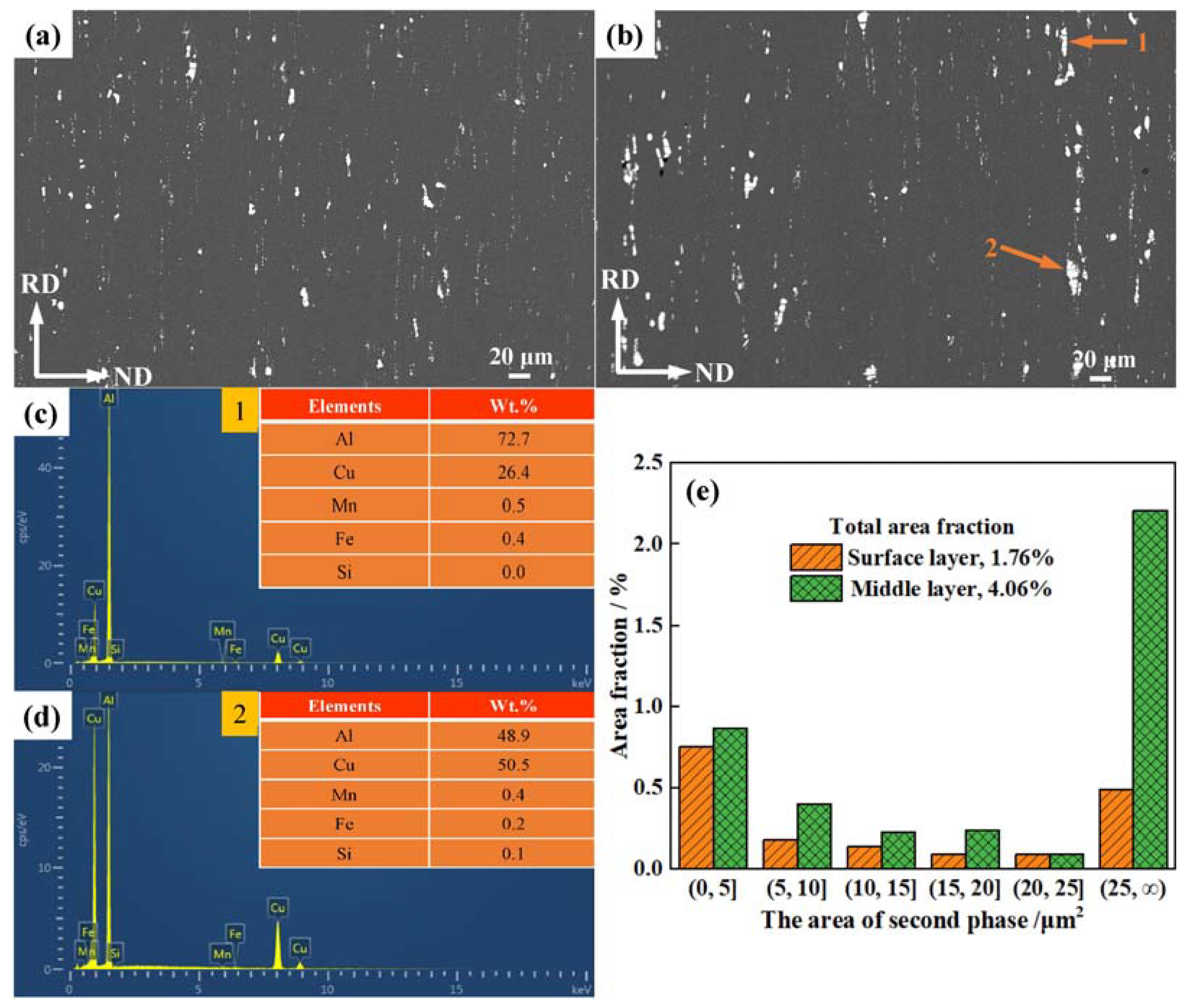
3.1. Microstructure Analysis

Figure 3 shows the metallographic structure of different layers along the thickness direction of 2519A aluminum alloy. The surface layer and the middle layer of the alloy are shown in Figure 3a and Figure 3b, respectively. It can be seen that the grains of different layers of the alloy are stretched along the rolling direction. From the surface layer to the middle layer, the average aspect ratios of the grains gradually increase (i.e., 5.4 and 7.1, respectively). This can be associated with the different deformability of thick plate in the different layers during the rolling process. The surface layer is seriously deformed due to the friction of the roller, and thus the grains of the layer were refined significantly in comparison with the middle layer. Hence, there were some small and irregular-shaped grains on the surface layer. From the surface layer to the middle layer, the shear effect weakened, and thus the deformation degree decreased. Therefore, the long strip grains can be observed in the middle layer. In addition, there were many black spots in the metallographic structure. These spots should be the second phases in the alloy. It is seen that the size and number of the phases gradually increase from the surface layer to the middle layer. More detailed information will be given in the next section.
Figure 4 shows the second phase distribution of different layers in 2519A aluminum alloy. The second phases were “chain-like” in different layers of the alloy. According to the EDS analysis, the second phase of the alloy contained Fe, Mn and Si. As can be seen from Figure 4, the coarse second phase in the alloy gradually increases from the surface layer to the middle layer. To further analyze this change, the size and the area fraction of second phase in the surface layer and middle layer were calculated by ImageJ software, and the results are shown in Figure 4e. According to the statistical results, the total area fraction of the second phase increased from 1.76% to 4.06% from the surface layer to the middle layer. The area of the second phase was mainly 0–25 μm2 in the surface layer, while the area of the second phase was mainly above 25 μm2 in the middle layer. The proportion of coarse second phase in the middle layer was obviously higher than that of the surface layer. The inhomogeneous distribution of these phases can be attributed to the following reasons. Firstly, the deformation of the surface layer was larger than that of the middle layer in the rolling process [4,18]. Hence, the second phase of the surface layer was more fragmented than that of the middle layer, and the size of the second phase was smaller. Secondly, the alloy elements in the middle layer were difficult to fully dissolve, so there were large numbers of insoluble phases containing Fe, Mn and Si in this layer. Thirdly, the cooling rate of specimens gradually decreased from the surface layer to the middle layer during the quenching process. The nonequilibrium solidification effect of the middle layer decreased, and thus the second phase in this layer was larger than the surface layer [22]. The analysis agrees with the metallographic structure in Figure 3.
Figure 5 shows the TEM images of 2519A aluminum alloy in the different layers and the electron diffraction (ED) patterns of the Al matrix and precipitates. The “cross-shaped” diffraction spot of the θ′ phase’s characteristic super lattice reflections can be observed in Figure 5 [23,24,25]. The θ′ phases possessed the same orientation relationship with the aluminum matrix (〈100〉 Al direction), which agreed with the results reported in [26]. It is obvious that the intensity of the spots in the middle layer was weaker than that of the surface layer. Furthermore, the θ′ precipitates were slender in the surface layer and turned relatively coarsened in the middle layer.
The variation of the precipitates was associated with the following reasons. Firstly, in the solid solution treatment process, it takes less time for soluting atoms in the surface layer to diffuse from the second phase into the aluminum matrix than they do in the middle layer. Therefore, the solid solution degree in the surface layer was higher than that of the middle layer, and the precipitation effect during the aging treatment was significantly better than that of the middle layer [27]. Secondly, in the quenching process, the cooling rate of the surface layer is higher than that of the middle layer. Therefore, there were more supersaturated solid solutions in the surface layer, and many fine θ′ phases were formed during the aging treatment. Thirdly, in the process of cold rolling before the aging treatment, the surface layer has a high degree of plastic deformation and a high dislocation density. During the aging stage, there were more nucleation points to form the precipitated phase, so the θ′ phase was slender and denser in the surface layer.

3.2. Mechanical Tensile Properties

Figure 6 shows the tensile properties of the 2519A aluminum alloy. The tensile strength of the alloy gradually decreases while the elongation gradually increases from the surface layer to the middle layer in the rolling direction. The tensile strength and yield strength of the RD-S specimen were 456 MPa and 425 MPa, with an elongation of 6.4%. Meanwhile, the tensile strength and yield strength of the RD-M specimen were 434 MPa and 390 MPa, with an elongation of 7.2%. Compared with the RD-S specimen, the ultimate tensile strength of the RD-M specimen decreased by 4.8%, the yield strength decreased by 8.2% and the elongations increased by 12.5%, respectively. In addition, the tensile properties in the thickness direction of the alloy were significantly different from those in the rolling direction. The tensile strength and yield strength of the ND specimen in the thickness direction were 414 MPa and 387 MPa, with an elongation of 3.9%. In comparison with the RD-M specimen, the tensile strength of the ND specimen was reduced by 20 MPa, and the elongation was reduced by 3.3%.
As can be seen from Figure 6, the tensile strength of the alloy along the thickness direction gradually decreased from the surface layer to the middle layer, and the elongation increased. The grains, second phases and precipitates were the main factors affecting the inhomogeneity of the strength of the alloy. Firstly, according to the Hall–Petch formula [28], the increase in the average aspect ratio of the grains leads to a decrease in the tensile strength from the surface layer to the middle layer. Secondly, the size and density of the coarsened phases gradually increased from the surface layer to the middle layer. The coarsened phases were detrimental to the strength of alloy [29]. The increase in the size and density of the coarsened phases contributes to a decrease in the tensile strength. Thirdly, the size of the θ′ phases increased, and the density decreased from surface layer to the middle layer. According to the precipitation-strengthening mechanism [28,30], the surface layer of the alloy with the smaller size and higher density of the precipitates presents a higher strength than the middle layer.
According to the Figure 6, the elongation of the alloy along the thickness direction gradually increased from the surface layer to the middle layer. The variation of elongation is mainly related to grain size. It has been reported that an increase in the average aspect ratio of grains will lead to an increase in lattice space to accommodate dislocations, thus improving the elongation [31]. As can be seen from the Figure 3, the average aspect ratio of grains from the surface layer to the middle layer increased from 5.4 to 7.1. This indicates that the grains in the middle layer have a strong capacity to accommodate dislocation. Therefore, the elongation of the middle layer is higher than that of the surface layer. In addition, Li et al. [32] discussed the dependence of uniform elongation on grain size in metal structural materials. They concluded that the relationship between elongation and grain size was as follows:
ε u = ε 0 1 A + B d
where, ε u is the elongation of alloy; ε 0 , A, and B are the parameters determined by the experiment for a material being investigated—these three parameters are constant for the same material; and d is the average grain diameter. According to Formula (2) and Figure 3, the elongation increases with an increase in the average aspect ratio of grains from the surface layer to the middle layer.
By comparing the RD-M specimen and the ND specimen, the elongation of the ND specimen especially was much lower than that of the RD-M specimen. This may be related to the equivalent distance between two adjacent coarse second phases in the alloy. Some researchers [33] have studied the effect of the coarse second phase on the plasticity of alloys and obtained the quantitative relationship between the coarse second phase and elongation, as shown below:
ε f ln ( A f c B ) ln C L c 3 r c 3 B
where ε f is the elongation; A, B and C are the constants; fc is the volume fraction of the coarse second phase; Lc is the average spacing of the coarse second phase; rc is the equivalent radius of the coarse second phase. The symbol stands for direct proportion. Figure 7 shows the statistical results of the average spacing of the second phase in the surface layer and middle layer. L0 and L1 represent the average spacing of the second phase in RD and ND, respectively. The statistical method of the average spacing of the second phase is as follows: Taking L0 as an example, (1) draw a line with length L (L equals the length of the SEM picture) and a direction parallel to the rolling direction on the SEM picture. (2) Count the number N of the second phase traversed by the line and calculate the average spacing of the second phase by using the formula L/N. (3) Move the line a certain distance along the thickness direction and repeat step (2). (4) Repeat step (3) to obtain 60 values and take their average as the final result. L1 is calculated in the same way. As can be seen from Figure 7, L0 is smaller than L1 in both layers. The L0 and L1 in the surface layer were 19.79 μm and 25.22 μm, whereas the L0 and L1 in the middle layer were 6.19 μm and 10.17 μm, respectively. The results indicate that the crack propagation distance in the adjacent second phase of the alloy subjected to the rolling direction load (L1) is much larger than that of the alloy subjected to the thickness direction load (L0). According to Formula (3), the elongation of the alloy under the rolling direction load is higher than that under the thickness direction load. In addition, the cavities inside the alloy are difficult to polymerize because the average spacing of the second phase is large and make the alloy more resistant to fracture. Therefore, the mechanical properties of the alloy in the rolling direction load are better than those in the thickness direction load.

3.3. Fatigue Properties

The curves of the da/dN v. ΔK from the replicate fatigue tests of the 2519A aluminum alloy under the rolling direction and thickness direction fatigue load are plotted in Figure 8. The specimen subject to the fatigue load in the rolling direction is named the RD specimen, and the specimen subject to the fatigue load in the thickness direction is named the ND specimen. As can be seen, all these curves present classical da/dN curve characteristics which can be divided into three stages [17]: stage I (the early stage), stage II (steady state stage) and stage III (the final stage). The FCP of specimens had obvious stage II and stage III, but the stage I was not apparent under the fatigue loads. In stage II, the FCGR curve of the RD specimen was flat, but that of the ND specimen was steep. The critical stress intensity factor values (ΔKcr) of the RD and ND specimens were 29.21 MPa·m1/2 and 16.32 MPa·m1/2, respectively. The ΔKcr values of the RD specimen were 79.0% higher than those of the ND specimen. To clarify the difference of FCGR under different directions of fatigue load, the fracture mechanics-based Paris power equation was adopted to analyze the experimental results. The Paris power equation [34] is shown below:
d a / d N = C ( Δ K ) m
where C and m are constants. Their values for the two specimens are listed in Table 2, and are evaluated from the linear region (stage II) of the plots of da/dN v. ΔK in Figure 8. Meanwhile, the values of da/dN at the specific ΔK are calculated and listed in Table 2. It can be seen from the experiment and fitting results that the FCGR of the RD specimen is significantly lower than that of the ND specimen—the alloy is more prone to fracture with weak FCP resistance under the ND fatigue load.
To further analyze the fracture behavior of alloy, the fatigue fractography of the specimens in the two directions was observed by SEM. Figure 9 shows the macroscopic morphology and fractography of the fatigue fracture surface of the CT specimens. A noticeable deflection of 98° (as shown in Figure 9a) occurred in the RD specimen during cyclic loading, while the crack path was flat in the ND specimen without similar crack deflection (Figure 9d). In steady state stage, the surface of the fatigue fracture in the RD specimen fluctuates greatly (Figure 9b). Cleavage steps, holes (as shown in the orange circle) and several secondary cracks are the main features at this stage. Moreover, it can be seen from the HDBSD image that some holes contain coarse second phase particles (Figure 9c). Compared to the RD specimen, the surface of the fatigue fracture in the ND specimen shows hybrid-fracture characteristics of a cleavage step and a fine fracture surface (shown in the blue dotted box in Figure 9e). The cleavage step of the fracture at this stage is flatter with small fluctuation. According to the HDBSD observation, the fine fracture surfaces are mainly formed by the fragmentation of second phases. Microcracks can be observed in these surfaces (Figure 9f). Comparing the HDBSD images of the RD and ND specimens, it can be seen that the clustering degree of coarse second phases in the RD specimen is low and the area of the coarse second phase is small (as shown in the red circles in the Figure 9c). However, the clustering degree of the broken coarse second phase in the ND specimen increases obviously (as shown in the blue dotted box in the Figure 9f), and the coarse second phase occupies a larger area. These differences may be related to the arrangement of the coarse second phase in the alloy, which will be discussed further later.
The microstructure, including grain and the second phase, play an important role in the FCP of aluminum alloy. These factors may lead to different crack propagation models, such as crack deflection and bifurcation, thereby resulting in different FCGR [35,36]. In this study, the effect of the microstructure on the fatigue behavior of the alloy mainly lies on the influence of the grain boundary and coarse second phase on the FCP.
It is known that grain boundary plays an important role in determining the fatigue property [36,37]. Figure 10 shows the optical images of fatigue crack at steady state stage in the CT specimen. As can be seen, the FCP mode of the RD specimen is transgranular crack propagation. Meanwhile, there are many intergranular microcracks near the main crack (indicated by the red arrow in Figure 10a). Different from RD specimen, the FCP mode of the ND specimen is inter/transgranular crack propagation (Figure 10b). The fatigue properties of the RD specimen are better than that of the ND specimen, which may be related to the grain boundary. On one hand, the grain boundary is regarded as a barrier for dislocation slip, promoting the decrease in slip reversibility and the increase in fatigue damage accumulation [37]. When the alloy is subjected to the rolling direction fatigue load, the fatigue crack passes through more grain boundaries. The fatigue crack propagation resistance is greater than that of the alloy under the thickness direction fatigue load. On the other hand, the microcracks are more likely to initiate and propagate due to the weak bonding force at the grain boundary when the alloy is subjected to fatigue loading in the thickness direction [38]. Therefore, the fatigue life in the thickness direction is lower than that in the rolling direction.
The massive research also indicated that the coarse second phase in the alloy has an important effect on the FCP [39,40]. The experimental results show that the fracture anisotropy of the 2519A aluminum alloy is determined by the degree of continuity of the second phase. The second phase was “chain-like” along the rolling direction in different layers of the alloy. The average spacing of the second phase in the thickness direction is significantly higher than in the rolling direction (as show in the Figure 7). The effect of the second phase on the fracture process of the alloy can be divided into two phases. Figure 11 shows the schematic diagram of influence of the second phase on the fracture process of the 2519A aluminum alloy.
Firstly, in the crack initiation and microcrack coalescence stage, the stress concentration occurs around the coarse second phase due to deformation inconsistency between the matrix and the second phase. Thus, the microcracks are easy to initiate in the coarse second phase under fatigue loading due to the stress concentration [39]. The cracking of the second phase changes the strain field in the surrounding matrix and creates a region of elevated strain in the close neighborhood. The process of microcrack coalescence is favored when the loading is in the ND due to the enhanced interaction of the strain fields around second phase (LRD is small) (see Figure 11c). On the contrary, when the loading is in the RD, there is less interaction of the local strain fields associated with the second phase due to their spatial distribution (LND is large) and the aggregation effect of the microcracks is weakened (see Figure 11a). In addition, the degree of microcrack coalescence in the alloy is also affected by the nonuniform microstructure and mechanical properties along the thickness direction. The damage degree of the alloy gradually decreases from the middle layer to the surface layer due to the synergistic deformation of microstructure when the alloy is subjected to the fatigue load in the thickness direction. The degree of microcrack coalescence is the highest in the middle layer and the lowest in the surface layer (see Figure 11c). However, due to the cooperative deformation of the microstructure, the damage degree of each layer was the same when the alloy was subjected to the fatigue load in the rolling direction. The resistance of the alloy to deformation is stronger than that under the thickness fatigue loading, and the microcracks do not coalesce easily (see Figure 11a).
Secondly, in the final fracture stage, the final fracture is triggered by the coalescence of microcracks which is favored when the load is in the thickness direction because the second phase is closer to one another. This proximity of second phases creates an easy percolating crack path along the rolling direction as a crack can extend along this direction throughout the material without the need to cross a tougher matrix material (see Figure 11d). On the opposite, the effect of the second phase particles on the aggregation of microcracks is weak when the load is in the rolling direction because the second phase is more isolated. The presence of a tougher matrix between these second phases greatly reduces the detrimental effect of microcrack aggregation and improves fracture performance (see Figure 11b).

4. Conclusions

The effect of microstructural heterogeneity on the mechanical properties of 2519A aluminum alloy thick plate was investigated. From the results and discussion, the mechanical properties of the alloys were mainly affected by the coarse second phase, grain boundary resistance and the inhomogeneous distribution of the microstructure. The main conclusions are as follows:
(1)
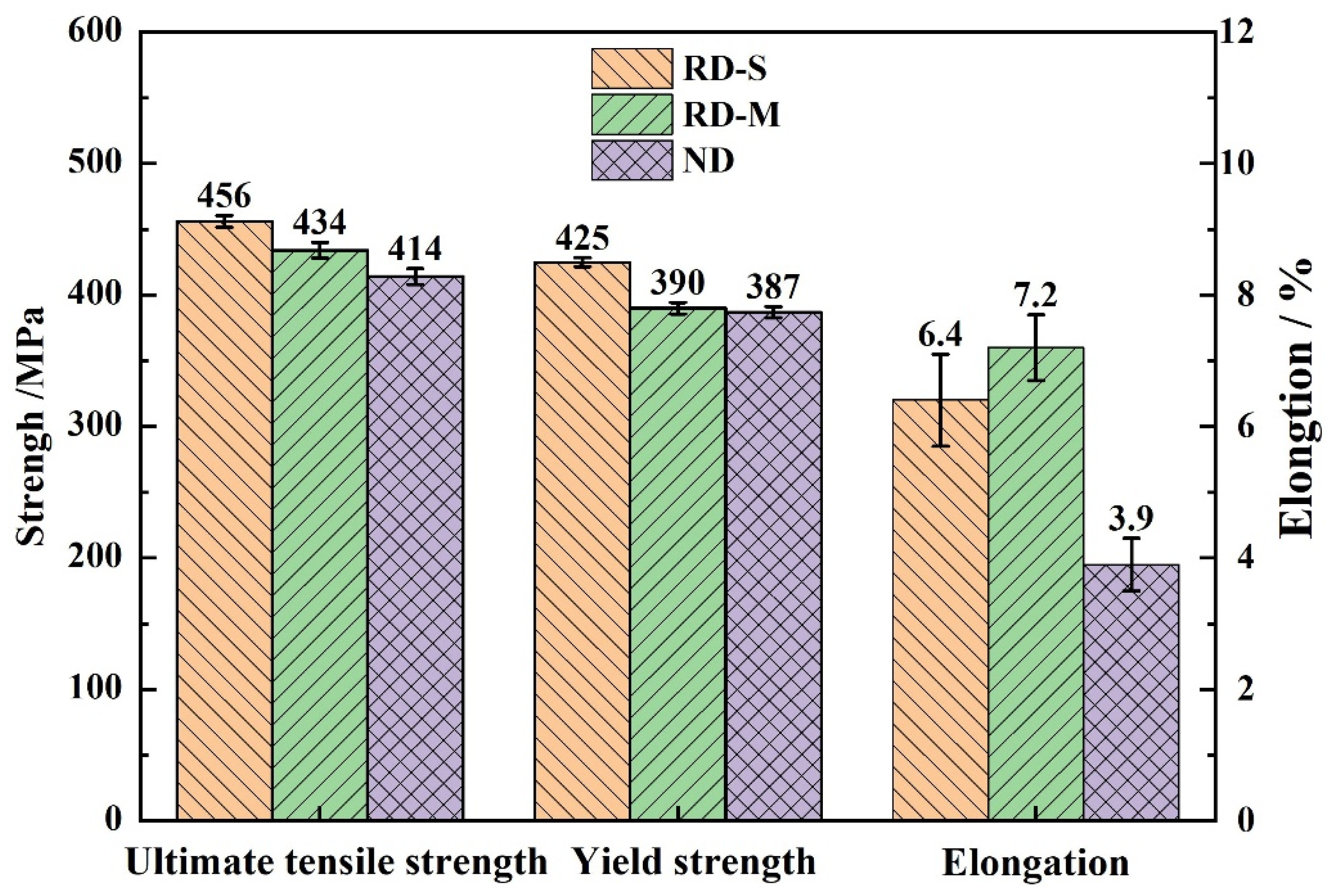
The tensile strength of the alloy decreases, and the elongation increases from surface layer to middle layer along the rolling direction. The tensile strength and elongation of the alloy in the thickness direction are 4.6% and 45.8% lower than those values in the rolling direction, respectively. The ΔKcr values of the RD specimen is 79.0% higher than that of the ND specimen.
(2)
The spacing between the adjacent second phase is the main factor affecting the mechanical properties of the alloys. The L0 and L1 in the surface layer are 19.79 μm and 25.22 μm, whereas the L0 and L1 in the middle layer are 6.19 μm and 10.17 μm, respectively (L0 and L1 represent the average spacing of the second phase in RD and ND). The crack propagation distance in the adjacent coarse second phase of the alloy subjected to the rolling direction load (L1) is much larger than that of the alloy subjected to the thickness direction load (L0). As a result, the microcracks tend to coalesce and bridge when the alloy is subjected to the thickness direction load. The alloy has weak fracture resistance and poor mechanical properties in the thickness direction.
(3)
The crack propagation mode of the RD sample is transgranular crack propagation, whereas that of the ND sample is intergranular/transgranular crack propagation. When dislocations pile up at grain boundaries, cracks are more likely to occur. These cracks are more likely to propagation along grain boundaries due to the weak binding force of grain boundaries, which makes the alloy is more likely to fracture under the thickness direction load.
(4)
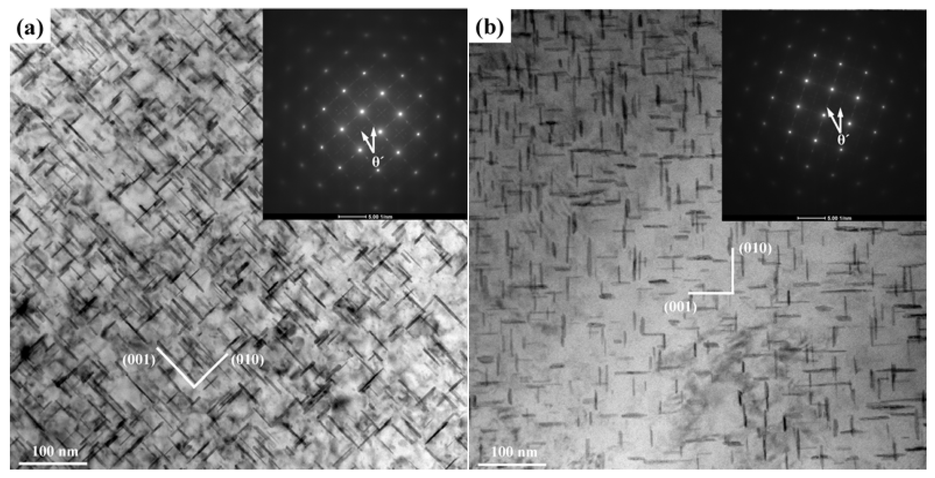
From the surface layer to the middle layer, the average aspect ratio of grains, the size and density of the coarsened Al(CuFeSiMn) phases gradually increases. The size of the θ′ phases increases, whereas the density in this phase decreases from surface layer to middle layer. The deformation of the alloy under the thickness direction load is not coordinated due to the inhomogeneous distribution of the microstructure, so the alloy is more prone to fracture.

Author Contributions

Conceptualization, Q.H., W.L., Y.S. and C.T.; methodology, Q.H. and W.L.; software, Q.H.; validation, C.T., C.Z. and M.X.; investigation, Q.H., C.Z. and M.X.; resources, C.Z. and W.L.; data curation, M.X.; writing—original draft preparation, Q.H.; writing—review and editing, Q.H., W.L. and Y.S.; supervision, W.L., C.T. and Y.S. All authors have read and agreed to the published version of the manuscript.

Funding

This research was funded by National Natural Science Foundation of China (grant numbers U21A20130, 51875197 and 52005177) and the Hunan Provincial Natural Science Foundation, China (grant number 2020JJ6027).

Institutional Review Board Statement

Not applicable.

Informed Consent Statement

Not applicable.

Data Availability Statement

Data presented in this article are available at request from the corresponding author.

Conflicts of Interest

The authors declare no conflict of interest.

References

  1. Ye, L.Y.; Dong, Y.; Zhang, Y.; Sun, D.X.; Zhang, X.M. Effect of test temperature and strain rate on dynamic mechanical behavior of aluminum alloy 2519A. J. Mater. Eng. Perform. 2019, 28, 4964–4971. [Google Scholar] [CrossRef]
  2. Selyutina, N.S. Prediction of the temperature-time effects of irreversible deformation for 2519A aluminum alloy. Phys. Mesomech. 2020, 23, 487–493. [Google Scholar] [CrossRef]
  3. She, X.W.; Jiang, X.Q.; Wang, P.Q.; Tang, B.B.; Chen, K.; Liu, Y.J.; Cao, W.N. Relationship between microstructure and mechanical properties of 5083 aluminum alloy thick plate. Trans. Nonferrous Met. Soc. China 2020, 30, 1780–1789. [Google Scholar] [CrossRef]
  4. Gong, H.; Cao, X.; Liu, Y.Q.; Wu, Y.X.; Jiang, F.M.; Zhang, M.H. Simulation and experimental study on the inhomogeneity of mechanical properties of aluminum alloy 7050 plate. Metals 2020, 10, 515. [Google Scholar] [CrossRef]
  5. Feng, L.; Pan, Q.L.; Wei, L.L.; Huang, Z.Q.; Liu, Z.M. Through-thickness inhomogeneity of localized corrosion in 7050-T7451 Al alloy thick plate. J. Cent. South Univ. 2015, 22, 2423–2434. [Google Scholar] [CrossRef]
  6. Liu, W.H.; He, Z.T.; Chen, Y.Q.; Tang, S.W. Dynamic mechanical properties and constitutive equations of 2519A aluminum alloy. Trans. Nonferrous Met. Soc. China 2014, 24, 2179–2186. [Google Scholar] [CrossRef]
  7. Wei, L.L.; Pan, Q.L.; Wang, Y.L.; Feng, L.; Huang, H.F. Characterization of fracture and fatigue behavior of 7050 aluminum alloy ultra-thick plate. J. Mater. Eng. Perform. 2013, 22, 2665–2672. [Google Scholar] [CrossRef]
  8. Chen, J.; Pan, Q.L.; Yu, X.H.; Li, M.J.; Zou, H.; Xiang, H.; Huang, Z.Q.; Hu, Q. Effect of annealing treatment on microstructure and fatigue crack growth behavior of Al–Zn–Mg–Sc–Zr alloy. J. Cent. South Univ. 2018, 25, 961–975. [Google Scholar] [CrossRef]
  9. Liu, W.H.; Cao, P.; Zhao, C.B.; Song, Y.F.; Tang, C.P. Effect of temperature and strain rate on crack behavior and deformation mode of 7B52 laminated aluminum alloy under impact loading. Met. Mater. Int. 2021, 27, 4397–4407. [Google Scholar] [CrossRef]
  10. Song, Y.F.; Ding, X.F.; Xiao, L.R.; Liu, W.H.; Chen, Y.Q.; Zhao, X.J. The effect of Ni plating on the residual stress and micro-yield strength in an Al-Cu-Mg alloy under different diffusion treatments. JOM 2019, 71, 4370–4377. [Google Scholar] [CrossRef]
  11. Li, Y.X.; Qiu, S.F.; Zhu, Z.T.; Han, D.Q.; Chen, J.Q.; Chen, H. Intergranular crack during fatigue in Al-Mg-Si aluminum alloy thin extrusions. Int. J. Fatigue 2017, 100, 105–112. [Google Scholar] [CrossRef]
  12. Song, Y.F.; Ding, X.F.; Zhao, X.J.; Xiao, L.R.; Yu, C.X. The effect of SiC addition on the dimensional stability of Al-Cu-Mg alloy. J. Alloys Compd. 2018, 750, 111–116. [Google Scholar] [CrossRef]
  13. Wu, W.T.; Liu, Z.Y.; Hu, Y.C.; Li, F.D.; Bai, S.; Xia, P.; Wang, A.; Ye, C.W. Goss texture intensity effect on fatigue crack propagation resistance in an Al-Cu-Mg alloy. J. Alloys Compd. 2018, 730, 318–326. [Google Scholar] [CrossRef]
  14. Zhao, K.; Liu, J.H.; Yu, M.; Li, S.M. Through-thickness inhomogeneity of precipitate distribution and pitting corrosion behavior of Al–Li alloy thick plate. Trans. Nonferrous Met. Soc. China 2019, 29, 1793–1802. [Google Scholar] [CrossRef]
  15. Yin, Y.; Luo, B.H.; Bai, Z.H.; Jing, H.B. Quench sensitivity of Al–Cu–Mg alloy thick plate. Rare Met. 2019, 1–9. [Google Scholar] [CrossRef]
  16. Zhou, L.; Chen, S.Y.; Chen, K.H.; Chang, J.H.; Huang, L.P. Effect of average pass reduction ratio on thickness-oriented microstructure and properties homogeneity of an Al–Zn–Mg–Cu aluminum alloy thick plate. Appl. Phys. A 2019, 125, 387. [Google Scholar] [CrossRef]
  17. Wu, P.F.; Deng, Y.L.; Zhang, J.; Fan, S.T.; Zhang, X.M. The effect of inhomogeneous microstructures on strength and fatigue properties of an Al-Cu-Li thick plate. Mater. Sci. Eng. A 2018, 731, 1–11. [Google Scholar] [CrossRef]
  18. Płonka, B.; Rajda, M.; Zamkotowicz, Z.; Żelechowski, J.; Remsak, K.; Korczak, P.; Szymański, W.; Śnieżek, L. Studies of the AA2519 Alloy Hot Rolling Process and Cladding with EN AW-1050A Alloy. Arch. Met. Mater. 2016, 61, 381–388. [Google Scholar] [CrossRef]
  19. Kotyk, M.; Boroński, D.; Maćkowiak, P. The influence of cryogenic conditions on the process of AA2519 aluminum alloy cracking. Materials 2020, 13, 1555. [Google Scholar] [CrossRef] [Green Version]
  20. Zuiko, I.; Gazizov, M.R.; Kaibyshev, R.O. Effect of thermomechanical treatment on the microstructure, phase composition, and mechanical properties of Al-Cu-Mn-Mg-Zr alloy. Phys. Met. Met. 2016, 117, 906–919. [Google Scholar] [CrossRef]
  21. Tu, J.; Wang, Y.N.; He, D.Y.; Peng, H.B.; Wen, Y.H. Ductile CuAlMn shape memory alloys with higher strength by Fe alloying and grain boundary engineering. Mater. Sci. Eng. A 2022, 841, 143032. [Google Scholar] [CrossRef]
  22. Ji, C.; Luo, S.; Zhu, M.Y.; Sahai, Y. Uneven solidification during wide-thick slab continuous casting process and its influence on soft reduction zone. ISIJ Int. 2014, 54, 103–111. [Google Scholar] [CrossRef] [Green Version]
  23. Ma, P.P.; Liu, C.H.; Wu, C.L.; Liu, L.M.; Chen, J.H. Mechanical properties enhanced by deformation-modified precipitation of θ′-phase approximants in an Al-Cu alloy. Mater. Sci. Eng. A 2016, 676, 138–145. [Google Scholar] [CrossRef]
  24. Yu, W.F.; Zhan, L.H.; Xu, Y.Q.; Chen, K.; Yang, Y.L.; Xu, L.Z.; Peng, N.H.; Ma, B.L.; Liu, C.; Chen, Z.C. Temperature-dependent creep aging behavior of 2A14 aluminum alloy. J. Mater. Res. Technol. 2022, 19, 1343–1354. [Google Scholar] [CrossRef]
  25. Sun, D.X.; Zhang, X.M.; Ye, L.Y.; Gu, G.; Jiang, H.C.; Gui, X.H. Evolution of θ′ precipitate in aluminum alloy 2519A impacted by split Hopkinson bar. Mater. Sci. Eng. A 2015, 620, 241–245. [Google Scholar] [CrossRef]
  26. Ye, L.Y.; Dong, Y.; Liu, S.D.; Jiang, H.C.; Sun, D.X.; Zhang, X.M. Effects of pre-ageing on microstructure and mechanical properties of T9I6 treated 2519A aluminum alloy. Met. Mater. Int. 2018, 24, 1149–1161. [Google Scholar] [CrossRef]
  27. Zhou, Z.Y.; Xiao, X.; Zhang, W.J.; Wang, F.C.; Ren, W.C.; Liu, C. Microstructure and Tensile Properties Anisotropy of 7xxx Ultra-Thick Plate. Mater. Sci. Forum 2021, 1035, 134–142. [Google Scholar] [CrossRef]
  28. Smith, W.F.; Hashemi, J. Foundations of Materials Science and Engineering, 6th ed.; Mcgraw-Hill Publishing: New York, NY, USA, 2019; pp. 432–438. [Google Scholar]
  29. She, H.; Shu, D.; Wang, J.; Sun, B.D. Influence of multi-microstructural alterations on tensile property inhomogeneity of 7055 aluminum alloy medium thick plate. Mater. Charact. 2016, 113, 189–197. [Google Scholar] [CrossRef]
  30. Dixit, M.; Mishra, R.S.; Sankaran, K.K. Structure–property correlations in Al 7050 and Al 7055 high-strength aluminum alloys. Mater. Sci. Eng. A 2008, 478, 163–172. [Google Scholar] [CrossRef]
  31. Zhang, Z.F.; Wang, Z.G. Dependence of intergranular fatigue cracking on the interactions of persistent slip bands with grain boundaries. Acta Mater. 2003, 51, 347–364. [Google Scholar] [CrossRef]
  32. Li, S.X.; Cui, G.R. Dependence of strength, elongation, and toughness on grain size in metallic structural materials. J. Appl. Phys. 2007, 101, 083525. [Google Scholar] [CrossRef]
  33. Zhang, G.J.; Wang, R.H.; Yuan, S.P.; Liu, G.; Scudino, S.; Sun, J.; Chen, K.H. Influence of constituents on the ductile fracture of Al–Cu–Mg alloys: Modulated by the aging treatment. Mater. Sci. Eng. A 2009, 526, 171–176. [Google Scholar] [CrossRef]
  34. Paris, P.; Erdogan, F. A Critical Analysis of Crack Propagation Laws. J. Basic Eng. 1963, 85, 528–533. [Google Scholar] [CrossRef]
  35. Huang, G.; Li, Z.H.; Sun, L.M.; Li, X.W.; Wen, K.; Yan, L.Z.; Xiong, B.Q.; Zhang, Y.A. Fatigue crack growth behavior of 2624-T39 aluminum alloy with different grain sizes. Rare Met. 2021, 40, 2523–2529. [Google Scholar] [CrossRef]
  36. She, X.W.; Jiang, X.Q.; Zhang, R.H.; Wang, P.Q.; Tang, B.B.; Du, E.C. Study on microstructure and fracture characteristics of 5083 aluminum alloy thick plate. J. Alloys Compd. 2020, 825, 153960. [Google Scholar] [CrossRef]
  37. Li, Z.H.; Guo, W.L. The influence of plasticity mismatch on the growth and coalescence of spheroidal voids on the bimaterial interface. Int. J. Plast. 2002, 18, 249–279. [Google Scholar] [CrossRef]
  38. Chen, Y.Q.; Pan, S.P.; Zhou, M.Z.; Yi, D.Q.; Xu, D.Z.; Xu, Y.F. Effects of inclusions, grain boundaries and grain orientations on the fatigue crack initiation and propagation behavior of 2524-T3 Al alloy. Mater. Sci. Eng. A 2013, 580, 150–158. [Google Scholar] [CrossRef]
  39. Meng, X.; Yang, S.L.; Huang, Y.B.; Fang, Y.; Gu, J.X.; Xiong, Q.; Duan, C.F. Microstructure characterization and mechanism of fatigue crack propagation of 6082 aluminum alloy joints. Mater. Chem. Phys. 2021, 257, 123734. [Google Scholar] [CrossRef]
  40. Xia, P.; Liu, Z.; Bai, S. Coupling Effect of Grain Structures and Residual Secondary Phases on Fatigue Crack Propagation Behavior in an Al-Cu-Mg Alloy. J. Mater. Eng. Perform. 2021, 30, 2669–2679. [Google Scholar] [CrossRef]
Figure 1. Sampling methods of mechanical tensile specimens.
Metals 12 01218 g001
Figure 2. The schematic diagrams of CT specimens: (a) the CT specimen size; (b) the enlarged view of area I in (a).
Metals 12 01218 g002
Figure 3. Optical images of 2519A aluminum alloy along the thickness direction: (a) Surface layer; (b) Middle layer.
Metals 12 01218 g003
Figure 4. The second phase distribution of 2519A aluminum alloy in the thickness direction: (a) Surface layer; (b) Middle layer; (c,d) EDS results of the second phase in (b); (e) the area fraction of second phase in (a,b).
Metals 12 01218 g004
Figure 5. The TEM micrographs of 2519A aluminum alloys in thickness direction: (a) Surface layer; (b) Middle layer.
Metals 12 01218 g005
Figure 6. Tensile properties of the 2519A aluminum alloy.
Metals 12 01218 g006
Figure 7. The average spacing of the second phase in the different directions.
Metals 12 01218 g007
Figure 8. FCGR under different loading directions.
Metals 12 01218 g008
Figure 9. Macroscopic morphology and fractography of fatigue fracture surface of CT specimen: (a,d) macroscopic photos of specimens; (b,e) SEM fractography of fatigue fracture surface in steady state stage at location I; (c,f) the backscattered electron detector (HDBSD) images of (b,e).
Metals 12 01218 g009
Figure 10. Optical images of fatigue crack at steady state stage in CT specimen: (a) RD specimen; (b) ND specimen.
Metals 12 01218 g010
Figure 11. The schematic diagram of influence of the second phase on fracture process of the 2519A aluminum alloy: (a,b) RD load, (c,d) ND load.
Metals 12 01218 g011
Table 1. Composition of 2519A aluminum alloy (Mass fraction/%).
ElementsCuFeMgMnNiSiTiZnZr
Content5.90.310.190.30.040.170.050.10.19
Table 2. Material parameters in the Paris power equation and values of da/dN at the specific ΔK.
Loading DirectionCmda/dN (mm/cycle)
ΔK = 11 MPa·m1/2ΔK = 13 MPa·m1/2ΔK = 15 MPa·m1/2
RD2.73 × 10−72.346.81 × 10−51.09 × 10−42.37 × 10−4
ND9.70 × 10−126.851.14 × 10−44.08 × 10−46.15 × 10−4
Publisher’s Note: MDPI stays neutral with regard to jurisdictional claims in published maps and institutional affiliations.

