
Predicting the Macroscopic Shear Strength of Tightened-Bonded Joints from the Intrinsic High-Pressure Properties of Anaerobic Adhesives

 , ,
, ,  , and
, and
Abstract
:1. Introduction
- -
- the adhesive filling the voids around the protrusions of the mating surfaces, which at zero contact pressure, exhibits its intrinsic shear strength;
- -
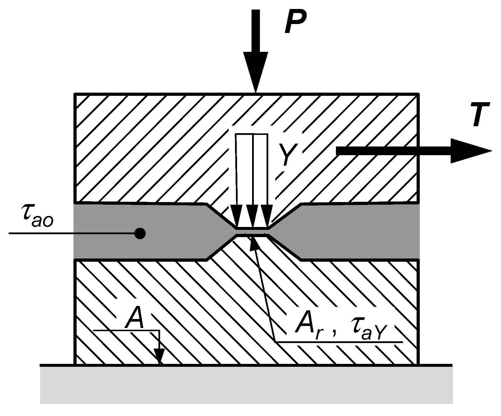
2. Micromechanical Model
2.1. Assumptions
2.2. Theory
3. Materials and Methods
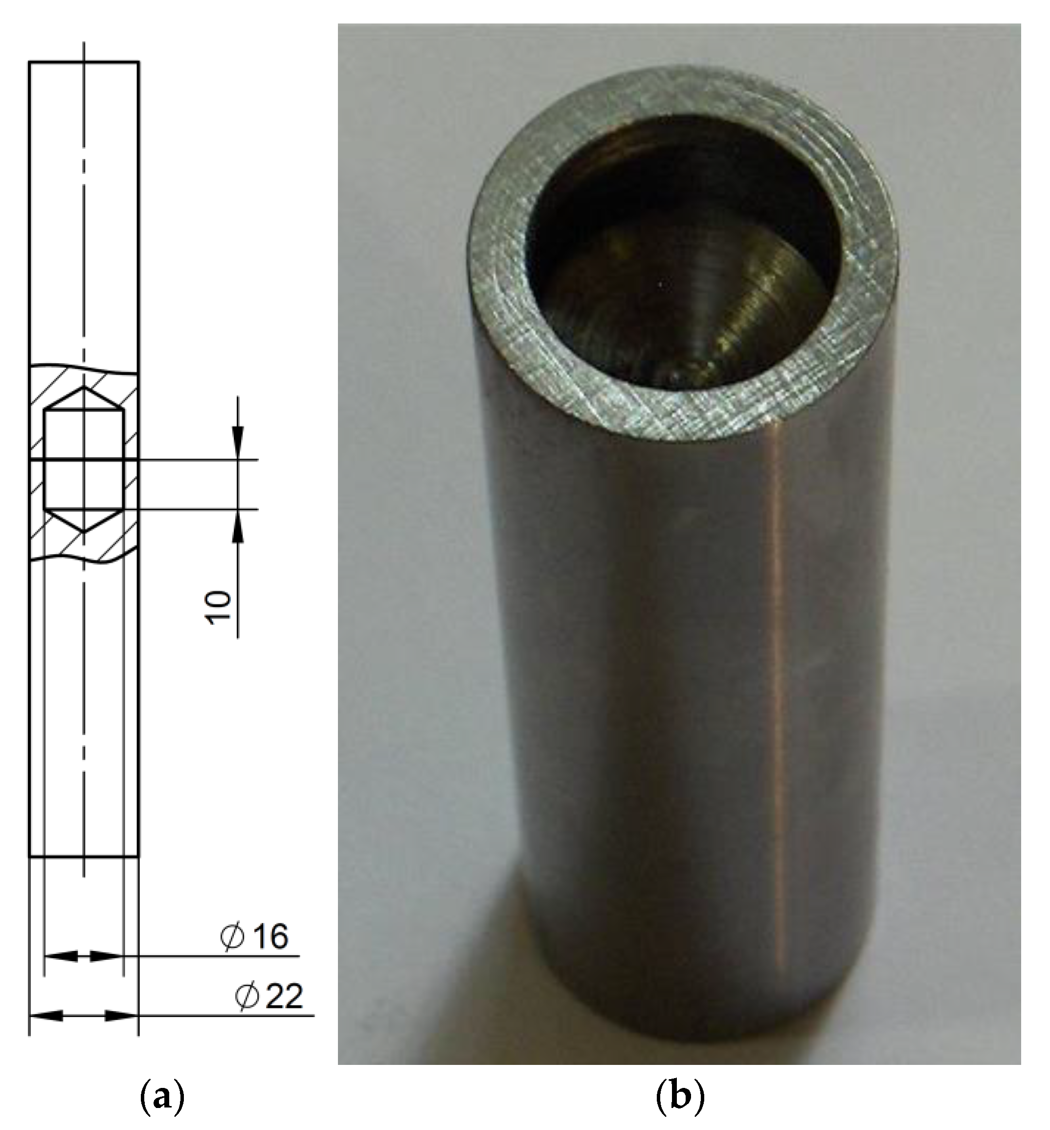
3.1. Adherends
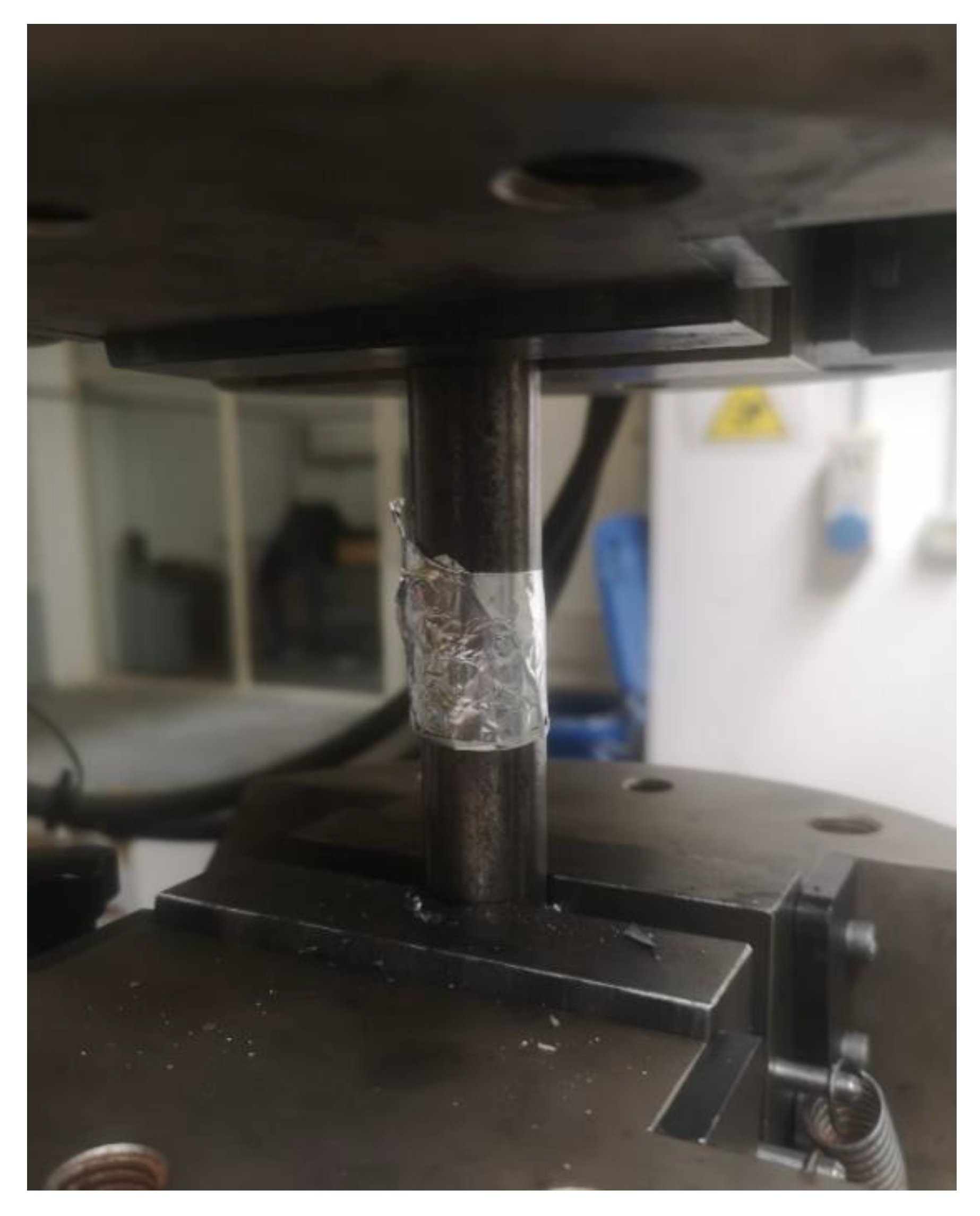
3.2. Test Bench and Test Procedure
3.3. Test Plan
4. Results
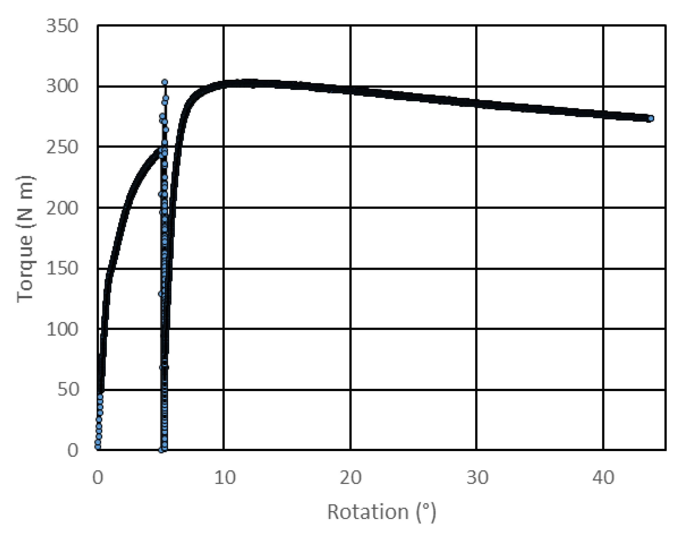
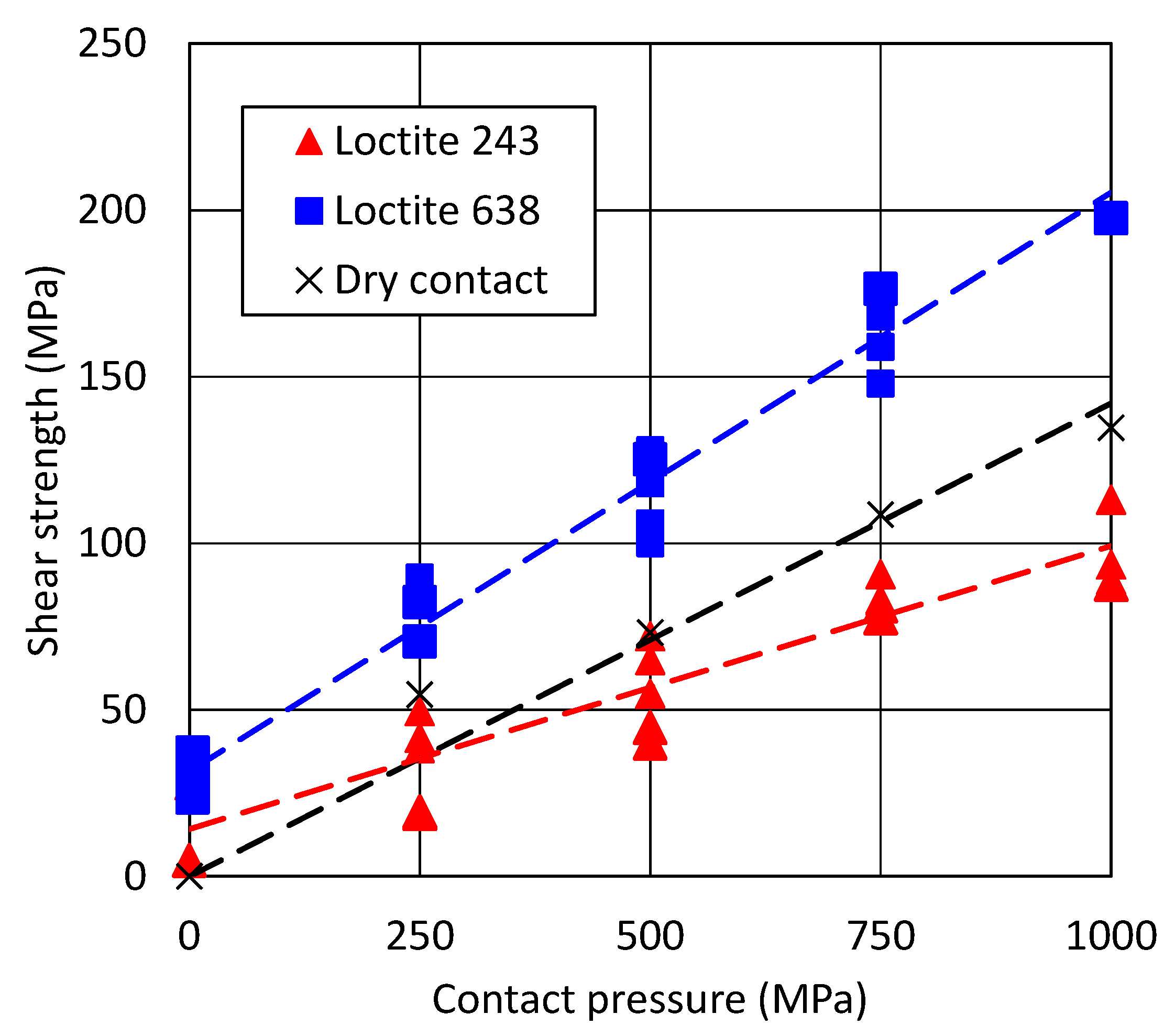
4.1. Test Results
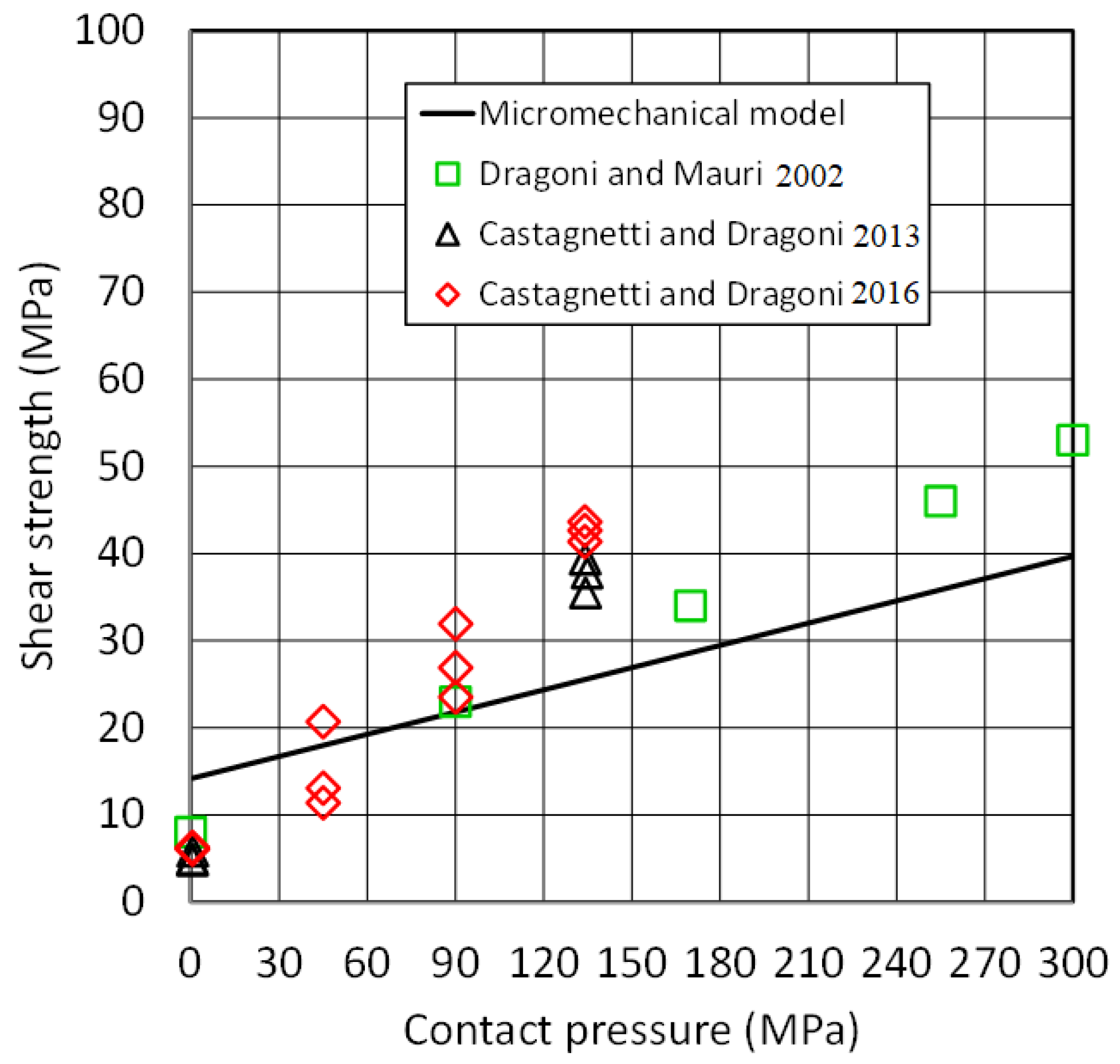
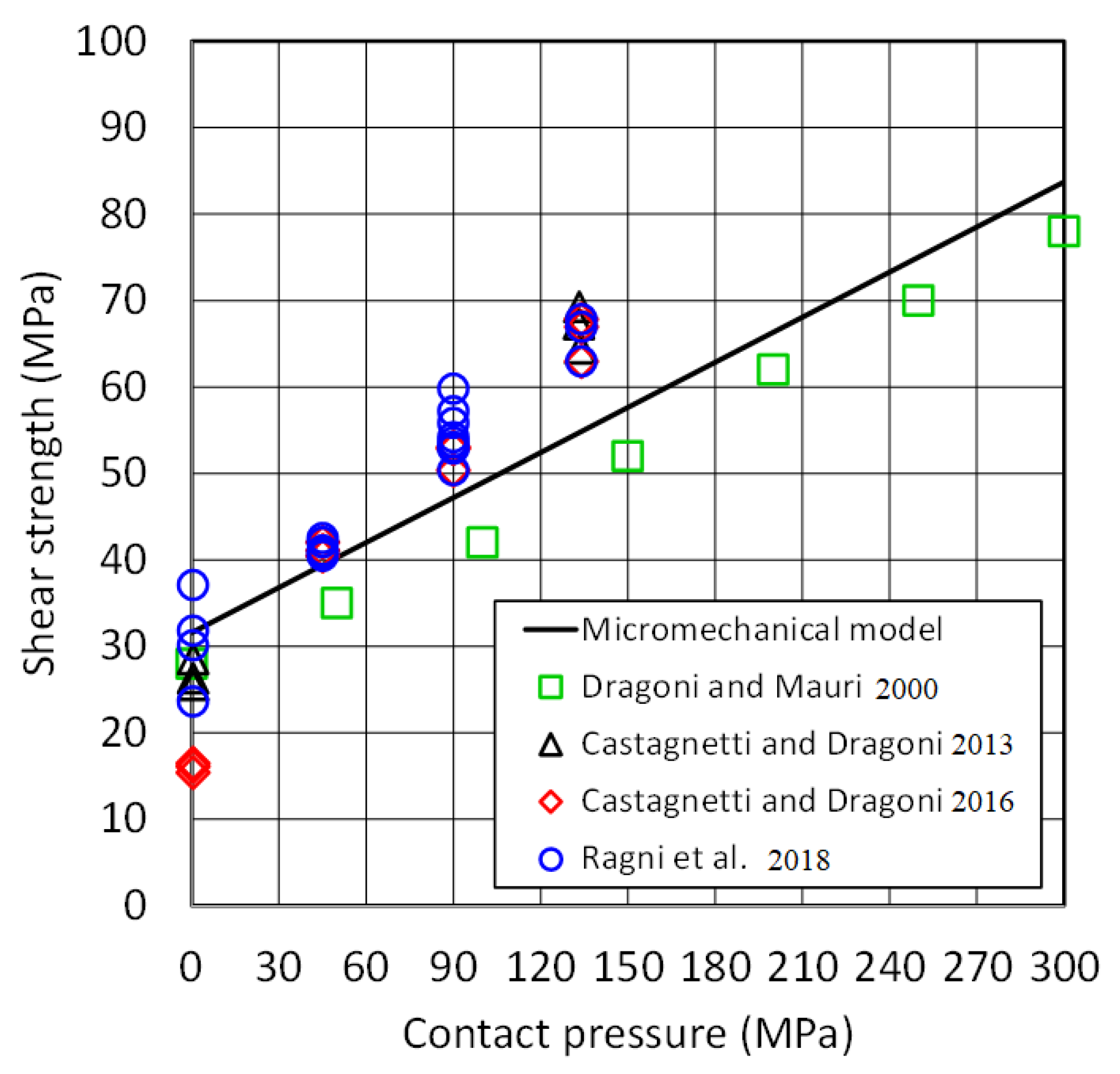
4.2. Model Evaluated in the Present Study and Validation with Collected Literature Results on Hybrid Joints
5. Discussion
6. Conclusions
Author Contributions
Funding
Informed Consent Statement
Data Availability Statement
Conflicts of Interest
References
- Dragoni, E.; Mauri, P. Intrinsic Static Strength of Friction Interfaces Augmented with Anaerobic Adhesives. Int. J. Adhes. Adhes. 2000, 20, 315–321. [Google Scholar] [CrossRef]
- Dragoni, E.; Mauri, P. Cumulative Static Strength of Tightened Joints Bonded with Anaerobic Adhesives. Proc. Inst. Mech. Eng. Part L J. Mater.Des. Appl. 2002, 216, 9–15. [Google Scholar] [CrossRef]
- Corigliano, P.; Crupi, V.; Pei, X.; Dong, P. DIC-Based Structural Strain Approach for Low-Cycle Fatigue Assessment of AA 5083 Welded Joints. Theor. Appl. Fract. Mech. 2021, 116, 103090. [Google Scholar] [CrossRef]
- Corigliano, P.; Crupi, V.; Guglielmino, E. Non Linear Finite Element Simulation of Explosive Welded Joints of Dissimilar Metals for Shipbuilding Applications. Ocean Eng. 2018, 160, 346–353. [Google Scholar] [CrossRef]
- Da Silva, L.F.M.; Pirondi, A.; Öchsner, A. Hybrid Adhesive Joints; Advanced Structured Materials; Springer: Berlin/Heidelberg, Germany, 2011; ISBN 9783642166235. [Google Scholar]
- Myslicki, S.; Kordy, H.; Kaufmann, M.; Créac’hcadec, R.; Vallée, T. Under Water Glued Stud Bonding Fasteners for Offshore Structures. Int. J. Adhes. Adhes. 2020, 98, 102533. [Google Scholar] [CrossRef]
- Adhesive Bonding. In Handbook of Plastics Joining; William Andrew Inc.: Norwich, NY, USA, 2009; pp. 145–173. [CrossRef]
- Piekarczyk, M.; Grec, R. Application of Adhesive Bonding in Steel and Aluminium Structures. Arch. Civ. Eng. 2012, 58, 309–329. [Google Scholar] [CrossRef] [Green Version]
- Albiez, M.; Damm, J.; Ummenhofer, T.; Ehard, H.; Schuler, C.; Kaufmann, M.; Vallée, T.; Myslicki, S. Hybrid Joining of Jacket Structures for Offshore Wind Turbines—Validation under Static and Dynamic Loading at Medium and Large Scale. Eng. Struct. 2022, 252, 113595. [Google Scholar] [CrossRef]
- Romanos, G. Strength Evaluation of Axisymmetric Bonded Joints Using Anaerobic Adhesives. Int. J. Mater. Prod. Technol. 1999, 14, 430–444. [Google Scholar] [CrossRef]
- Yoneno, M.; Sawa, T.; Shimotakahara, K.; Motegi, Y. Axisymmetric Stress Analysis and Strength of Bonded Shrink-Fitted Joints Subjected to Push-Off Forces. JSME Int. J. Ser. A 1997, 40, 362–374. [Google Scholar] [CrossRef] [Green Version]
- Sekercioglu, T. Shear Strength Estimation of Adhesively Bonded Cylindrical Components under Static Loading Using the Genetic Algorithm Approach. Int. J. Adhes. Adhes. 2005, 25, 352–357. [Google Scholar] [CrossRef]
- Sekercioglu, T.; Meran, C. The Effects of Adherend on the Strength of Adhesively Bonded Cylindrical Components. Mater. Des. 2004, 25, 171–175. [Google Scholar] [CrossRef]
- Sekercioglu, T.; Gulsoz, A.; Rende, H. The Effects of Bonding Clearance and Interference Fit on the Strength of Adhesively Bonded Cylindrical Components. Mater. Des. 2005, 26, 377–381. [Google Scholar] [CrossRef]
- Mengel, R.; Häberle, J.; Schlimmer, M. Mechanical Properties of Hub/Shaft Joints Adhesively Bonded and Cured under Hydrostatic Pressure. Int. J. Adhes. Adhes. 2007, 27, 568–573. [Google Scholar] [CrossRef]
- Aronovich, D.A.; Murokh, A.F.; Sineokov, A.P.; Khamidulova, Z.S. Study of the Properties of Anaerobic Adhesives Cured in Cylindrical Joints. Polym. Sci. Ser. D 2008, 1, 260–265. [Google Scholar] [CrossRef]
- Sineokov, A.P.; Aronovich, D.A.; Murokh, A.F.; Khamidulova, Z.S. Mechanism of Initiation of the Curing of Anaerobic Adhesives. Int. Polym. Sci. Technol. 2008, 35, 31–38. [Google Scholar] [CrossRef]
- Croccolo, D.; de Agostinis, M.; Vincenzi, N. Static and Dynamic Strength Evaluation of Interference Fit and Adhesively Bonded Cylindrical Joints. Int. J. Adhes. Adhes. 2010, 30, 359–366. [Google Scholar] [CrossRef]
- Croccolo, D.; de Agostinis, M.; Mauri, P.; Olmi, G. Influence of the Engagement Ratio on the Joint Strength of Press Fitted and Adhesively Bonded Specimens. Int. J. Adhes. Adhes. 2014, 53, 80–88. [Google Scholar] [CrossRef]
- Croccolo, D.; de Agostinis, M.; Vincenzi, N. Design and Optimization of Shaft-Hub Hybrid Joints for Lightweight Structures: Analytical Definition of Normalizing Parameters. Int. J. Mech. Sci. 2012, 56, 77–85. [Google Scholar] [CrossRef]
- Croccolo, D.; de Agostinis, M.; Fini, S.; Olmi, G. An Experimental Study on the Response of a Threadlocker, Involving Different Materials, Screw Dimensions and Thread Proportioning. Int. J. Adhes. Adhes. 2018, 83, 116–122. [Google Scholar] [CrossRef]
- Croccolo, D.; de Agostinis, M.; Fini, S.; Olmi, G.; Paiardini, L.; Robusto, F. Threaded Fasteners with Applied Medium or High Strength Threadlockers: Effect of Different Tightening Procedures on the Tribological Response. J. Adhes. 2020, 96, 64–89. [Google Scholar] [CrossRef]
- Croccolo, D.; de Agostinis, M.; Fini, S.; Olmi, G.; Paiardini, L.; Robusto, F. Effects of Aging Temperature and Humidity on the Response of Medium and High Strength Threadlockers. J. Adhes. 2021, 98, 721–738. [Google Scholar] [CrossRef]
- Croccolo, D.; de Agostinis, M.; Fini, S.; Olmi, G.; Paiardini, L.; Robusto, F. Temperature Response of LOCTITE 648 Anaerobic Adhesive and Hoop Channels to Enhance Its Effectiveness under High Interference. J. Adhes. 2021, 1–25. [Google Scholar] [CrossRef]
- Oinonen, a.; Marquis, G. A Parametric Shear Damage Evolution Model for Combined Clamped and Adhesively Bonded Interfaces. Eng. Fract. Mech. 2011, 78, 163–174. [Google Scholar] [CrossRef]
- Oinonen, a.; Marquis, G. Shear Decohesion of Clamped Abraded Steel Interfaces Reinforced with Epoxy Adhesive. Int. J. Adhes. Adhes. 2011, 31, 550–558. [Google Scholar] [CrossRef]
- Hurme, S.; Oinonen, a.; Marquis, G. Fatigue of Bonded Steel Interfaces under Cyclic Shear Loading and Static Normal Stress. Eng. Fract. Mech. 2011, 78, 1644–1656. [Google Scholar] [CrossRef]
- Kleiner, F.; Fleischmann, W. Technologies of Threadlocking and Interference-Fit Adhesive Joints. Adv. Struct. Mater. 2011, 6, 227–255. [Google Scholar] [CrossRef]
- Gallio, G.; Marcuccio, G.; Bonisoli, E.; Tornincasa, S.; Pezzini, D.; Ugues, D.; Lombardi, M.; Rovarino, D.; Fino, P.; Montanaro, L. Study of the Interference Contribution on the Performance of an Adhesive Bonded Press-Fitted Cylindrical Joint. Int. J. Adhes. Adhes. 2014, 53, 89–96. [Google Scholar] [CrossRef]
- Abdel Wahab, M.M. Fatigue in Adhesively Bonded Joints: A Review. ISRN Mater. Sci. 2012, 2012, 746308. [Google Scholar] [CrossRef]
- Dragoni, E. Fatigue Testing of Taper Press Fits Bonded with Anaerobic Adhesives. J. Adhes. 2003, 79, 729–747. [Google Scholar] [CrossRef]
- Croccolo, D.; de Agostinis, M.; Vincenzi, N. How to Improve Static and Fatigue Strength in Press-Fitted Joints Using Anaerobic Adhesive. Proc. Inst. Mech. Eng. Part C J. Mech. Eng. Sci. 2011, 225, 2792–2803. [Google Scholar] [CrossRef]
- Croccolo, D.; de Agostinis, M.; Vincenzi, N. Experimental Analysis of Static and Fatigue Strength Properties in Press-Fitted and Adhesively Bonded Steel–Aluminium Components. J. Adhes. Sci. Technol. 2011, 25, 2521–2538. [Google Scholar] [CrossRef]
- Raghava, R.; Caddell, R.M.; Yeh, G.S.Y. The Macroscopic Yield Behaviour of Polymers. J. Mater. Sci. 1973, 8, 225–232. [Google Scholar] [CrossRef] [Green Version]
- Schlimmer, M. Anstrengungshypothese Für Metallklebverbindungen. Materwiss Werksttech 1982, 13, 215–221. [Google Scholar] [CrossRef]
- Chow, T.S. Stress–Strain Behavior of Polymers in Tension, Compression, and Shear. J. Rheol. 1998, 36, 1707. [Google Scholar] [CrossRef]
- Zhang, J.; Jin, T.; Wang, Z.; Zhao, L. Experimental Investigation on Yield Behavior of PMMA under Combined Shear–Compression Loading. Results Phys. 2016, 6, 265–269. [Google Scholar] [CrossRef] [Green Version]
- Spaggiari, A.; Castagnetti, D.; Dragoni, E. A Design Oriented Multiaxial Stress-Based Criterion for the Strength Assessment of Adhesive Layers. Compos. Part B Eng. 2019, 157, 66–75. [Google Scholar] [CrossRef]
- Castagnetti, D.; Dragoni, E. Predicting the Macroscopic Shear Strength of Adhesively-Bonded Friction Interfaces by Microscale Finite Element Simulations. Comput. Mater. Sci. 2012, 64, 146–150. [Google Scholar] [CrossRef]
- Castagnetti, D.; Dragoni, E. Experimental Assessment of a Micro-Mechanical Model for the Static Strength of Hybrid Friction-Bonded Interfaces. J. Adhes. 2013, 89, 642–659. [Google Scholar] [CrossRef] [Green Version]
- Castagnetti, D.; Dragoni, E. Adhesively-Bonded Friction Interfaces: Macroscopic Shear Strength Prediction by Microscale Finite Element Simulations. Int. J. Adhes. Adhes. 2013, 53, 57–64. [Google Scholar] [CrossRef]
- Castagnetti, D.; Dragoni, E. Experimental Investigation and Model Validation of the Shear Strength of Hybrid Interfaces up to Complete Failure. J. Adhes. 2016, 92, 679–697. [Google Scholar] [CrossRef] [Green Version]
- Ragni, M.; Castagnetti, D.; Dragoni, E. Experimental Validation of a Simple Shear Strength Model for Hybrid Friction-Bonded Interfaces. Int. J. Adhes. Adhes. 2018, 83, 130–136. [Google Scholar] [CrossRef]
- Corigliano, P.; Ragni, M.; Castagnetti, D.; Crupi, V.; Dragoni, E.; Guglielmino, E. Measuring the Static Shear Strength of Anaerobic Adhesives in Finite Thickness under High Pressure. J. Adhes. 2019, 97, 783–800. [Google Scholar] [CrossRef]
- Henkel Loctite® 243TM, Technical Data Sheet 2010. Available online: https://www.henkel-adhesives.com/uk/en/product/threadlockers/loctite_243.html (accessed on 28 June 2022).
- Henkel Loctite® 638, Technical Data Sheet 2004, 80–82. Available online: https://www.henkel-adhesives.com/uk/en/product/retaining-compounds/loctite_638.html (accessed on 28 June 2022).


| Variables | Levels | ||||||
|---|---|---|---|---|---|---|---|
| Adhesive Type | Loctite 243 | Loctite 638 | Dry Contact | ||||
| Nominal contact pressure (MPa) | 0 | 250 | 500 | 750 | 1000 | ||
| Nominal Contact Pressure | Failure Torque (Nm) | ||
|---|---|---|---|
| (MPa) | 243 | 638 | Dry Contact |
| 0 | 46.7 | 51.2 | 0.0 |
| 0 | 8.1 | 40.1 | - |
| 0 | - | 54.1 | - |
| 0 | - | 63.1 | - |
| 0 | - | 44.2 | - |
| 250 | 65.6 | 140.0 | 92.9 |
| 250 | 70.9 | 120.0 | - |
| 250 | 84.4 | 151.0 | - |
| 250 | 32.0 | 120.0 | - |
| 250 | 33.0 | 152.6 | - |
| 500 | 110.5 | 210.0 | 124.6 |
| 500 | 93.3 | 229.0 | - |
| 500 | 122.7 | 237.0 | - |
| 500 | 76.0 | 213.0 | - |
| 500 | 68.0 | 223.0 | - |
| 750 | 154.4 | 291.5 | 184.8 |
| 750 | 141.4 | 285.7 | - |
| 750 | 140.9 | 300.0 | - |
| 750 | 132.0 | 296.0 | - |
| 750 | 138.0 | 300.0 | - |
| 1000 | 151.4 | 336.0 | 229.1 |
| 1000 | 192.4 | - | - |
| 1000 | 159.3 | - | - |
| 1000 | 149.0 | - | - |
| 1000 | - | - | - |
| Adhesive Type | Loctite 243 | Loctite 638 | Dry Contact |
|---|---|---|---|
| (MPa) | 14.16 | 31.58 | 0 |
| 0.0851 | 0.1738 | 0.1421 |
Publisher’s Note: MDPI stays neutral with regard to jurisdictional claims in published maps and institutional affiliations. |
© 2022 by the authors. Licensee MDPI, Basel, Switzerland. This article is an open access article distributed under the terms and conditions of the Creative Commons Attribution (CC BY) license (https://creativecommons.org/licenses/by/4.0/).
Share and Cite
Castagnetti, D.; Corigliano, P.; Barone, C.; Crupi, V.; Dragoni, E.; Guglielmino, E. Predicting the Macroscopic Shear Strength of Tightened-Bonded Joints from the Intrinsic High-Pressure Properties of Anaerobic Adhesives. Metals 2022, 12, 1141. https://doi.org/10.3390/met12071141
Castagnetti D, Corigliano P, Barone C, Crupi V, Dragoni E, Guglielmino E. Predicting the Macroscopic Shear Strength of Tightened-Bonded Joints from the Intrinsic High-Pressure Properties of Anaerobic Adhesives. Metals. 2022; 12(7):1141. https://doi.org/10.3390/met12071141
Chicago/Turabian StyleCastagnetti, Davide, Pasqualino Corigliano, Calogero Barone, Vincenzo Crupi, Eugenio Dragoni, and Eugenio Guglielmino. 2022. "Predicting the Macroscopic Shear Strength of Tightened-Bonded Joints from the Intrinsic High-Pressure Properties of Anaerobic Adhesives" Metals 12, no. 7: 1141. https://doi.org/10.3390/met12071141