Article

Fatigue Crack Initiation on Semi-Solid Al–7Si–Mg Castings

1
Department of Materials and Manufacturing, School of Engineering, Jönköping University, P.O. Box 1026, SE-55111 Jönköping, Sweden
2
School of Mechanical Engineering and Rail Transit, Changzhou University, Changzhou 213164, China
3
Department of Industrial Engineering, Trento University, Via Sommarive 9, 38123 Trento, Italy
*
Author to whom correspondence should be addressed.
Metals 2022, 12(7), 1061; https://doi.org/10.3390/met12071061
Submission received: 13 May 2022 / Revised: 15 June 2022 / Accepted: 18 June 2022 / Published: 21 June 2022

Abstract

:
Four-point bending fatigue tests were performed on semi-solid Al–7Si–Mg castings with varying magnesium contents and heat treatment conditions. Additionally, the effect of anodising on the fatigue resistance of semi-solid Al–7Si–Mg castings was evaluated. Fracture surface and microstructure analysis showed that fatigue crack initiation occurred mainly at the periphery of regions of positive macrosegregation at the casting surface, resulting most likely from exudation. The microstructure of these macrosegregation regions was mostly eutectic and was frequently found surrounded by a layer of oxides. This layer of oxides promoted weak bonding between the macrosegregation region and the surrounding material and acted as a crack initiation site. In this study, primary α-Al globule agglomerates at the casting surface and surrounded by a layer of oxides also promoted fatigue crack initiation. Fatigue resistance of semi-solid Al–7Si–Mg castings in the T5 and T6 conditions increased with the increase in the magnesium content of the alloy from 0.3 to 0.45 wt.% due to the higher precipitation hardening response. However, the increase in the magnesium content from 0.45 to 0.6 wt.% resulted in a slight decrease in the fatigue resistance. The oxide layer formed during anodising had no significant effect on the fatigue resistance of the semi-solid Al–7Si–Mg castings in this study due to the dominant effect of the macrosegregation regions on fatigue crack initiation.

1. Introduction

Most of the fatigue life of technical components in the high cycle regime is governed by crack initiation and propagation of microstructural short cracks [1,2]. Crack initiation usually occurs at or near the surface of the material, resulting from defects or microstructural heterogeneities at which stress concentration is very high [1]. Castings defects at the surface or subsurface govern the fatigue life of Al–7Si–Mg castings by decreasing the periods of crack initiation and propagation [3,4]. Shrinkage or gas porosities and oxides are commonly reported as the main crack initiation defects [4,5,6]. Morphology [7], size [8,9], and location of defects in the cross-section of the casting [10] influence the fatigue behavior of the castings significantly. Semi-solid metal (SSM) castings commonly have fewer shrinkage and gas entrapment defects than high-pressure die castings (HPDC) [11].
SSM Al–7Si–Mg castings typically have a longer fatigue life than permanent mould castings of the same alloy in high cycle fatigue regimes (>104 cycles) [12]. The lower defect content of the SSM castings compared to the permanent mould castings delays the fatigue crack initiation [12,13]. The smaller grain size of SSM castings also hinders the fatigue crack propagation due to the higher density of the grain boundaries, which results in the longer fatigue life of SSM castings compared to permanent mould castings [12,13]. Surface segregation is commonly found in direct-chill casting [14], HPDC [15,16,17], and SSM casting [18,19,20] products and results in heterogeneous properties along the cross-section of the castings [14]. Gourlay et al. [21] suggested that the surface segregation layer formation in HPDC results from a combination of inverse segregation and exudation mechanisms. In inverse segregation, solute-enriched liquid flows towards the casting surface through the interdendritic regions to compensate for solidification shrinkage and thermal contraction [21]. Exudation occurs when the solidifying surface of the casting starts to shrink and gains enough strength to pull away from the die wall, forming a gap between the solidifying casting surface and the die wall [17]. Consequently, if the pressure differential between the gap and the interior of the alloy is high enough, the solute-enriched liquid can flow through interdendritic channels [17], or hot tears [14], into the space between the solidifying alloy and the die wall. This exudated solute-enriched liquid solidifies into a nearly fully eutectic microstructure [14,22]. The migration of externally solidified crystals towards the casting centre during filling also contributes to surface segregation [22]. Low gate flow speed, application of intensification pressure, and lower casting temperatures promote exudation in magnesium high-pressure die castings [23]. Therefore, process parameters that commonly result in lower microporosity in HPDC promote exudation [23]. Few studies were found relating to the effect of surface segregation on fatigue. However, the few studies found showed that surface segregation is detrimental to the fatigue life of castings [15,24].
Anodising is a surface treatment used to improve aluminium alloys’ corrosion and wear resistances [20]. The brittle nature and irregularities of the oxide layer formed on the aluminium alloys’ surface during anodising can negatively affect fatigue resistance [25]. Additionally, fatigue resistance tends to decrease with the increase in the oxide layer thickness obtained after anodising [25]. However, most of the studies reporting this behaviour were performed on wrought alloys.
This work identified the primary defects that result in fatigue crack initiation on SSM Al–7Si–Mg castings with varying magnesium contents and heat treatment conditions. The effect of anodising on crack initiation and fatigue properties was also investigated. Additionally, the formation of the defects was discussed and correlated to the flow and solidification conditions during the SSM casting process.

2. Experimental

2.1. Alloys

About 80 kg of Al–7Si–0.3Mg, Al–7Si–0.4Mg, and Al–7Si–0.45Mg ingots were melted at 700 °C in a graphite-bonded silicon carbide crucible using an electrical resistance furnace. The Al–7Si–0.6Mg alloy was prepared by the addition of Al–7Si–0.45Mg ingots and magnesium wrapped in aluminium foil to the bottom of the graphite-bonded silicon carbide crucible to obtain the intended alloy composition after melting. The chemical compositions after melting were measured using a SPECTROMAXx Metal Analyzer (Spectromaxx CCD LMXM3, Spectro Analytical Instruments, Cleves, Germany) with the results shown in Table 1. At least two batches were prepared for each alloy.

2.2. Semi-Solid Castings

The SSM castings were produced using the Rheometal™ process [26]. A so-called enthalpy exchange material (EEM) was cast in a copper mould with a Ø40 mm cylindrical cavity. A 12 mm diameter stainless steel rod was cast 10 mm deep into the EEM base. The EEM height was adjusted to generate an addition corresponding to 7 wt.% of the total shot weight. Before immersion, the EEMs were preheated to 200 °C in an air circulation electrical resistance furnace and connected to the stirring device through the steel rod. About 1.3 kg of superheated aluminium alloy was ladled from the crucible, and, as the temperature of the liquid reached 650 °C (with an approximate liquidus temperature of 612 °C and solidus temperature of 555 °C), the preheated EEM was immersed while rotating at 850 rpm to produce the slurry. The slurry preparation process took about 18 s. When the slurry preparation process was complete, the slurry was immediately poured into the shot sleeve of a 50 tonne vertical high-pressure die casting machine and injected into the die cavity to produce tensile bars, as shown in Figure 1a. The solid fraction was mass based and kinetic, resulting in a slurry temperature of 611–612 °C. Before experimentation started, a set of high-pressure die castings were produced to warm up the assembly and maintain reproducible thermal conditions in the shot sleeve and die cavity during the experiment. The casting parameters were kept constant in all tests with a plunger advance speed of 0.3 m/s and an intensification pressure of 160 bar. A duration of 10 s was set for the intensification pressure and the cooling stages of the casting in the interior of the die cavity. However, the SSM castings, heat-treated to the T5 condition, were immediately extracted from the die cavity after the intensification pressure stage and immersed into a water bath at room temperature to minimise precipitation during cooling. A PolyTemp HTF 300 heater was used to maintain a constant flow of oil at 175 °C in the interior of the die to reduce temperature variations in the die between castings.

2.3. Heat Treatments

The SSM Al–7Si–Mg cast tensile bars were heat-treated to the T6 and T5 conditions with the parameters previously investigated [27]. The T6 heat treatment consisted of a solution treatment performed in a Nabertherm L40/11 muffle furnace at 510 °C for 4 h, followed by quenching in a water bath at room temperature. Within 24 h of quenching, the solution-treated samples were aged at 190 °C for 2 h in an air circulation electrical furnace.
The T5 treatment was performed within a period of 24 h after casting. The T5 treatment of the tensile bars varied with composition. The SSM Al–7Si–0.3Mg and Al–7Si–0.45Mg cast tensile bars were artificially aged at 175 °C for 4.5 h, while the Al–7Si–0.6Mg tensile bars were artificially aged at 180 °C for 4.5 h in an air circulation electrical furnace. The temperatures and holding times used for the different heat treatments in this study were based on a separate study of the optimised heat treatment procedure to minimise blistering occurrence during solution treatment and achieve peak hardness during ageing.

2.4. Anodising

The anodising process was performed in a 1.0 M H2SO4 solution at room temperature at a constant voltage of 16 V for 15 min to investigate the influence of the anodised layer on fatigue properties. The oxide layer thickness of the tested samples was around 3 µm. In the current study, prior to anodising, the samples were ultrasonically cleaned in ethanol for 5 min. After anodising, the samples were rinsed in distilled water and dried.

2.5. Tensile Testing

Tensile testing was performed at room temperature in a Zwick/Roell Z100 testing machine (ZWICKRoell Group, Ulm-Einsingen, Germany) according to the SS-EN ISO 6892-1:2016 [28]. A constant strain rate of 0.00025 s−1 was used up to the offset 0.2% yield strength, where the strain rate was increased to 0.002 s−1 and kept constant until fracture. The elongation was measured continuously by a laser Zwick/Roell LaserXtens extensometer (ZWICKRoell Group, Ulm-Einsingen, Germany). At least three samples were tested for each condition.

2.6. Four-Point Bending Fatigue

Four-point bending fatigue tests were carried out on the SSM Al–7Si–Mg castings using an MTS LandMark™ servo-hydraulic test machine with stress amplitude set following linear elastic mechanics. The nominal stress was calculated according to the beam mechanical theory [29]:
σ = 3 P ( L a ) b t 2
where P is the load applied, b and t are the width and thickness of the specimens, respectively, and a is the distance between the loading and support plates. The measured average surface roughness of the castings was 1.07 ± 0.32 μm in Ra using a Taylor Hobson stylus. The fatigue tests were carried out at room temperature under load control using sinusoidal loading at a frequency of 10 Hz and a stress ratio of R = −1. A layer of tape was placed between the samples’ surface and the support and loading plates of the four-point bending fixture to reduce friction between the contacts during testing. The samples were carefully aligned before fixation to the position. After testing, the fracture surfaces of each specimen were analysed using a JEOL JSM-7001F Scanning Electron Microscope (SEM) to identify the crack initiation defects.

2.7. Characterisation

Samples were either sectioned along the dashed line shown in Figure 1a for observation of the cross-section or cut transversely to observe the surface layer microstructure of the castings. Subsequently, both the cross-section and surface of the samples were ground, and the polishing was complete with OP-U suspension before observation. During polishing, a depth of ≤190 µm of the surface layer was removed. Optical micrographs were acquired using an Olympus GX71F. The SEM equipped with energy-dispersive X-ray spectroscopy (EDS) was used for EDS point analysis at a fixed acceleration voltage of 15 kV. The compositions of the different regions in the surface layer were obtained by EDS point analysis on at least two SSM castings per condition.
The size of the different iron-rich phases was determined by measuring the longest line segment that could be drawn within the contour of the intermetallic phase. The longest line segment lengths of at least 30 iron-rich intermetallic phases were measured on optical micrographs taken with a magnification of 1000× near the cross-section centre of each specimen.
The manual point count method from ASTM E562-11 [30] was used for determination of the area fraction of the iron-rich and Mg2Si phases in the eutectic regions observed on the optical micrographs. At least four different regions near the cross-section centre were analysed for each specimen condition. The area fraction of the intermetallics determined for the eutectic regions was multiplied by the fraction of eutectic calculated by Thermocalc™ using the Scheil–Gulliver model to obtain the area fraction of the intermetallics in each specimen. The magnification used for determination of the area fraction of the different intermetallic phases was 1000× for all the samples analysed.
In this work, two populations of grains were observed in the microstructures. The large α-Al globules observed in the microstructure that likely formed during slurry preparation and in the shot sleeve are denoted as α1. The smaller α-Al observed in the microstructures, <25 µm in diameter, was identified as in-cavity solidified grains [31]. The general denotation α-Al is used when the distinction of the different α-Al in the SSM casting is irrelevant.

3. Results

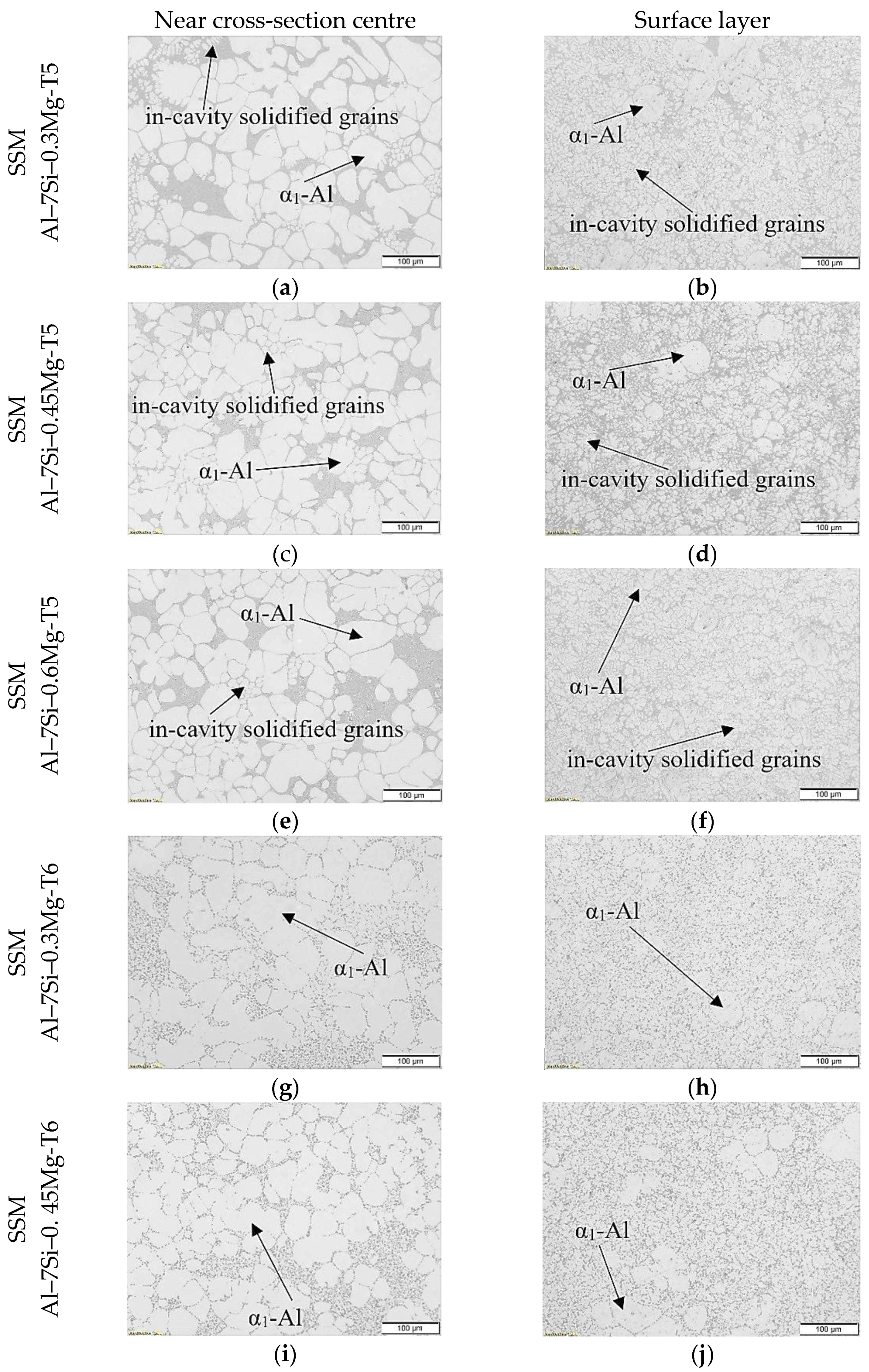
3.1. Microstructural Analysis

Figure 2 shows optical micrographs from near the cross-section centres and from the surface layer of the SSM Al–7Si–Mg castings in the T5 and T6 conditions. The eutectic microstructure for each sample is shown in Figure 3. The microstructure near the cross-section centre of the Al–7Si–Mg castings in both T5 and T6 conditions consisted of primary α1-Al globules, a few small, in-cavity solidified grains, and eutectic, as shown in Figure 2. A significant lower fraction of primary α1-Al globules and a higher fraction of in-cavity solidified grains were observed in the surface layer than near the cross-section centre, as shown in Figure 2. The primary α1-Al globules were concentrated in the casting centre, similar to the externally solidified crystals in HPDC [32]. The packing of the primary α1-Al globules towards the casting centre may have resulted from a combination of mechanisms, such as the Magnus lift [32] and Mukai-Lin-Laplace effects [33], during die cavity filling. Consequently, fewer primary α1-Al globules and a large fraction of in-cavity solidified dendritic α-Al grains were observed in the surface layer, as shown in Figure 2.
The eutectic regions of the SSM Al–7Si–0.3Mg casting surface in the T5 condition contained iron-rich, plate-like π-Al8FeMg3Si6 and modified Al–Si eutectic phases, as reported in other studies for similar alloys [20]. No significant differences in the microstructure were found for the SSM Al–7Si–0.3Mg castings in the as-cast and T5 conditions. The higher magnesium content of both SSM Al–7Si–0.45Mg and Al–7Si–0.6Mg castings resulted in the formation of the Mg2Si phase in the eutectic regions in addition to iron-rich, plate-like π-Al8FeMg3Si6 and modified Al–Si eutectic phases, as seen in Figure 3b,c, respectively. The microstructure of the SSM Al–7Si–0.4Mg casting was identical to the SSM Al–7Si–0.45Mg castings, and, for this reason, it is not shown in Figure 2.
The T6 heat treatment changed the eutectic microstructure of the SSM Al–7Si–Mg castings’ surface compared to the same alloy castings in the T5 condition, in addition to strengthening the α-Al matrix by precipitation hardening. Spheroidised eutectic silicon and a minor fraction of iron-rich intermetallic phases surrounded by an α-Al phase were observed in the eutectic regions of the SSM castings’ surface in the T6 condition, as shown in Figure 2d through Figure 2j and Figure 3d,e. No Mg2Si phase was observed in either castings’ surface in the T6 condition, which suggests that it was dissolved during the solution treatment, as reported in other studies [34]. Wang and Davidson [34] showed an incomplete dissolution of the π-Al8FeMg3Si6 phase for Al–7Si–Mg castings with magnesium content higher than 0.4 wt.%. It seems that a significant portion of the π-Al8FeMg3Si6 phase remained after solution treatment of the higher magnesium SSM casting surface in the T6 condition, as showed in the highlighted image of Figure 2j. However, for the SSM Al–7Si–0.3Mg casting in the T6 condition it appears that the π-Al8FeMg3Si6 phase was mostly transformed into thin β-Al5FeSi platelets, as shown in Figure 3d and reported in other studies for alloys with similar magnesium levels [34].

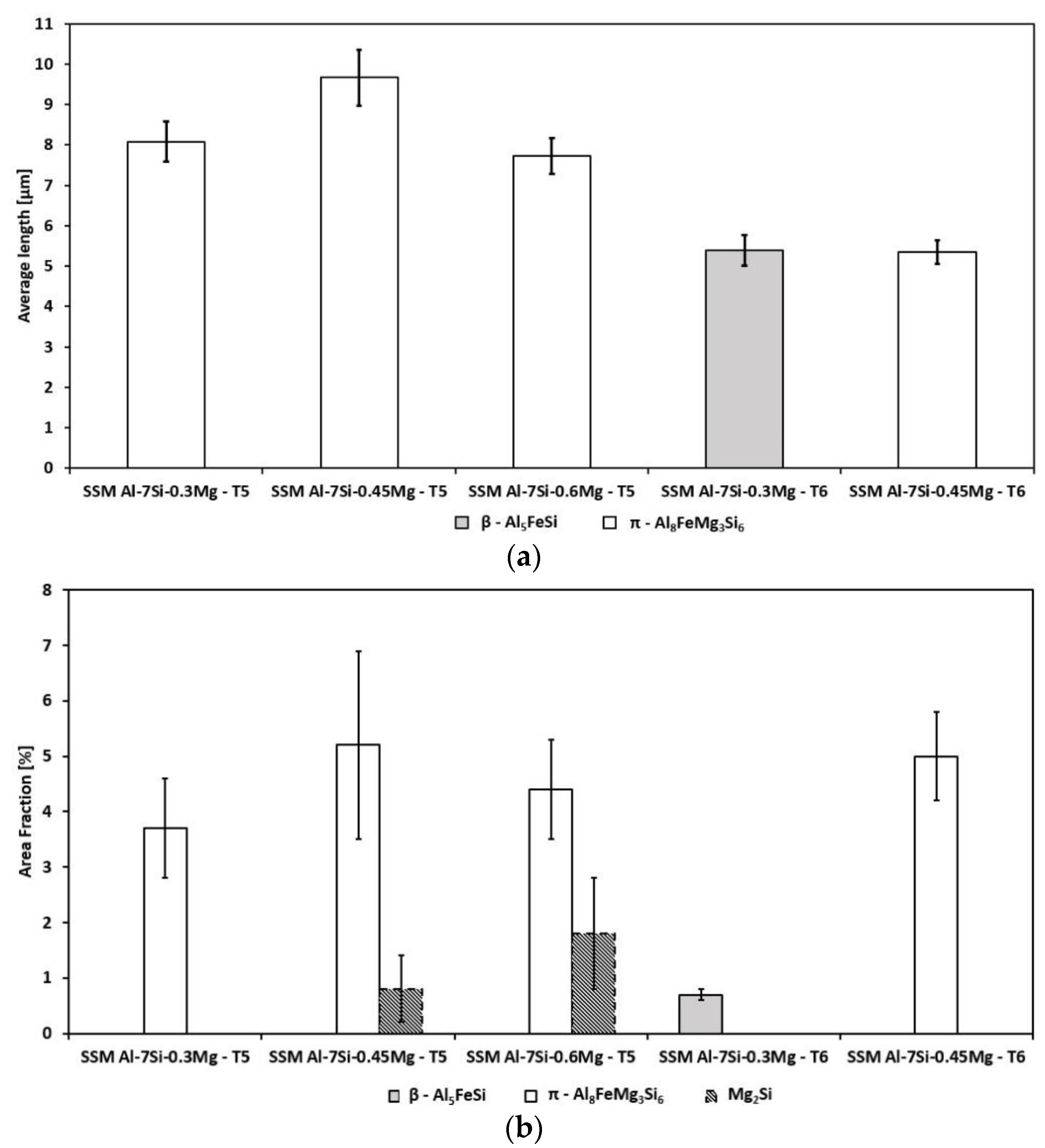
3.2. Size and Area Fraction of Intermetallic Phases

The increase in the magnesium content of the casting did not have a clear effect on the size of the iron-rich intermetallic phases obtained for the SSM Al–7Si–Mg castings in the T5 conditions, as shown in Figure 4a. A slightly larger π-Al8FeMg3Si6 phase was obtained for the SSM Al–7Si–0.45Mg casting in the T5 condition in comparison to both the SSM Al–7Si–0.3Mg and SSM Al–7Si–0.6Mg castings in the same condition, as shown in Figure 4a. After T6 heat treatment, smaller, iron-rich intermetallic phases were obtained for all castings. However, no differences in size were obtained for the β-Al5FeSi phase of the SSM Al–7Si–0.3Mg casting in the T6 condition and the π-Al8FeMg3Si6 phase for the SSM Al–7Si–0.45Mg casting in the same condition.
Figure 4b shows the area fraction of the different intermetallic phases detected in the selected SSM castings. There was no significant influence on the fraction of π-Al8FeMg3Si6 phase caused by the increase in the magnesium content for the SSM Al–7Si–Mg castings in the T5 condition. However, in addition to the π-Al8FeMg3Si6 phase, the Mg2Si phase was detected for the SSM Al–7Si–Mg castings in the T5 condition with magnesium contents higher than 0.3 wt.%, as shown in Figure 4b. It seems that the Mg2Si phase fraction tended to be lower for the SSM Al–7Si–0.45Mg casting in the T5 condition in comparison to the SSM Al–7Si–0.6Mg casting in the same condition. The fraction of intermetallic phases decreased after T6 heat treatment, particularly for the SSM Al–7Si-0.3–Mg casting, as show in Figure 4b.

3.3. Effect of Heat Treatment and Magnesium Content on Tensile Properties

Figure 5 shows the tensile properties obtained for the SSM Al–7Si–Mg castings in the different conditions. The increase in the magnesium content of the SSM Al–7Si–Mg castings resulted in an increase in the 0.2% offset yield strength for both T5 and T6 conditions. The 0.2% offset yield strength was significantly higher for the SSM castings in the T6 condition than the castings with the same composition in the T5 condition. However, the 0.2% offset yield strength increased slightly for the SSM Al–7Si–0.3Mg casting in the T5 heat treatment in comparison to the casting with the same composition in the as-cast condition. Therefore, precipitation hardening occurred to some extent in the SSM Al–7Si–0.3Mg castings in the T5 condition.
The tensile strength was similar for both SSM Al–7Si–0.3Mg casting in the as-cast and T5 condition, as shown in Figure 5. No significant differences were obtained for the tensile strength for the SSM Al–7Si–0.3Mg and Al–7Si–0.45Mg castings in the T5 condition. Both SSM Al–7Si–0.4Mg and Al–7Si–0.6Mg castings in the T5 conditions showed slightly higher tensile strength in comparison with the other SSM castings in the same condition. The tensile strength increased after T6 heat treatment for all SSM castings in comparison to both as-cast and T5 conditions.
The highest elongation was obtained for the SSM Al–7Si–0.3Mg casting in the as-cast conditions, as shown in Figure 5. After T5 heat treatment, the elongation obtained for the SSM Al–7Si–0.3Mg castings decreased. The increase in the magnesium content did not affect the elongation of the castings in the T5 condition, except the SSM Al–7Si–0.4Mg casting, which appeared to have a slightly higher elongation than the castings with higher magnesium contents. The increase in the magnesium content of the SSM Al–7Si–Mg castings in the T6 condition resulted in a decrease in the elongation, as shown in Figure 5. A higher elongation was obtained for the SSM Al–7Si–0.3Mg castings in the T6 condition in comparison to the T5 condition while, for the SSM Al–7Si–0.45Mg castings, no significant differences were obtained. Figure 4 shows that a significant fraction of the π-Al8FeMg3Si6 phase remained in the microstructure for the SSM Al–7Si–0.45Mg casting after the T6 heat treatment, which can explain the low elongation obtained. A larger scatter in the elongation values was obtained for the SSM Al–7Si–0.3Mg castings than for the other castings with higher magnesium contents, which is an indication of higher defect content in the SSM Al–7Si–0.3Mg castings.

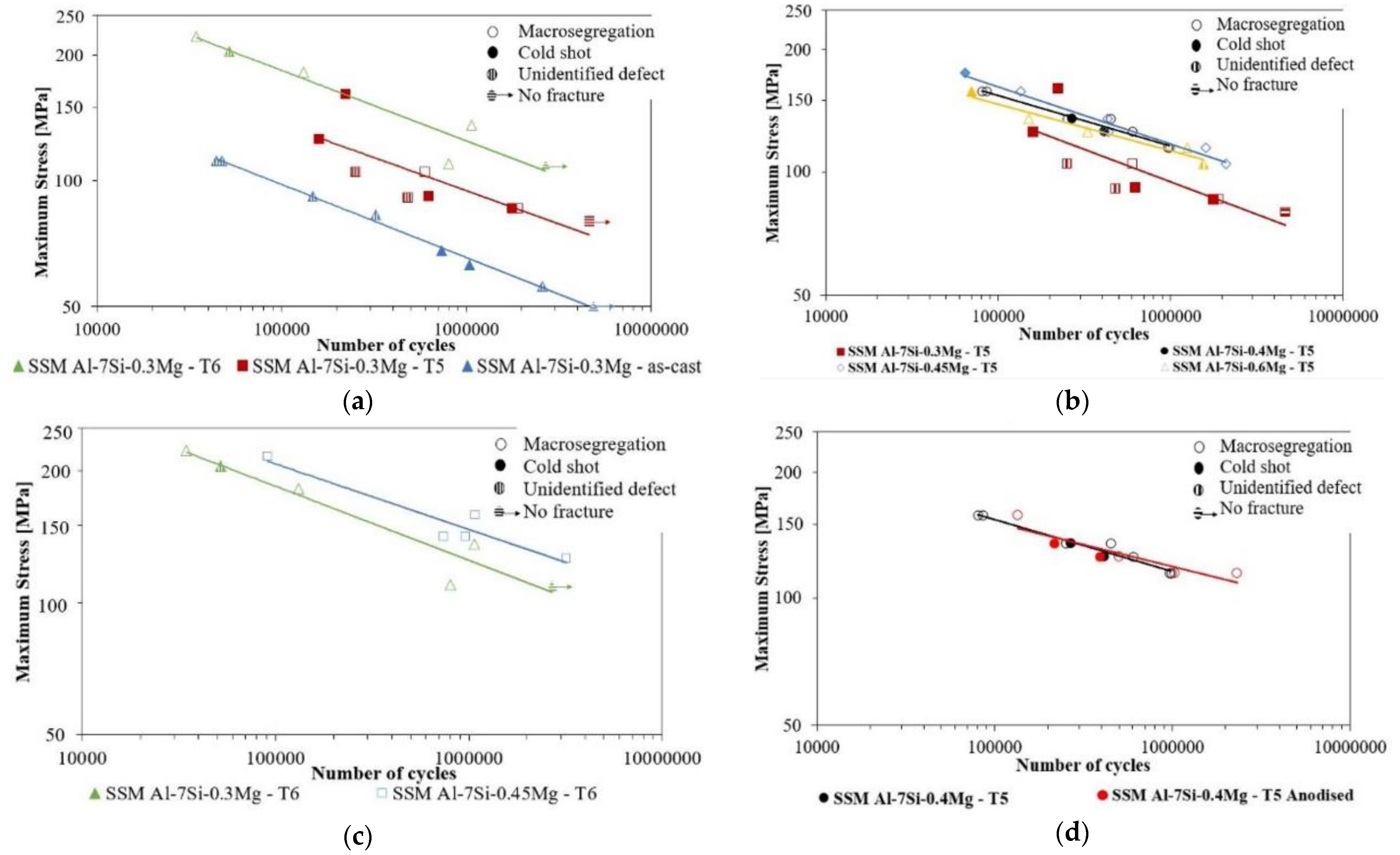
3.4. Effect of Heat Treatment and Magnesium Content on Fatigue Properties

The four-point bending fatigue results are shown in Figure 6 as SN curves in which the different marker filling patterns indicate the defect at which the fatigue crack initiated. It seems that the four-point bending fatigue life of the SSM Al–7Si–0.3Mg castings increased with the increase in the precipitation hardening obtained during ageing to the T5 and T6 conditions, as shown in Figure 6a. Therefore, the SSM casting in the as-cast condition had the lowest fatigue life compared to both T5 and T6 conditions. The SSM Al–7Si–0.3Mg castings in the T5 condition showed greater scattering in the fatigue results. Both macrosegregation and cold shots located at the casting surface initiated fatigue cracks in the SSM Al–7Si–0.3Mg castings in the T5 condition. However, for the SSM Al–7Si–0.3Mg castings in both as-cast and T6 condition, just one defect type was identified that started fatigue cracks, cold shot, and macrosegregation. Defects of various shapes, sizes, and locations result in larger scattering in fatigue life [35]. The fact that two types of defect were found to initiate fatigue cracks in the SSM Al–7Si–0.3Mg castings in the T5 condition may explain the higher scattering in the fatigue results compared to the other SSM castings shown in Figure 6a.
Fatigue life increased with the increase in magnesium content from 0.3 to 0.40 wt.% of the SSM castings in the T5 condition, as shown in Figure 6b. The increase in the magnesium content from 0.4 to 0.45 wt.% of the SSM Al–7Si–Mg castings in the T5 condition did not significantly affect the fatigue life. For the SSM Al–7Si–Mg castings in the T6 condition, the increase in the magnesium content from 0.3 to 0.45 wt.% increased the fatigue life, as shown in Figure 6c. The increase in the magnesium content from 0.3 to 0.45 wt.% for the SSM castings in both T5 and T6 conditions resulted in an enhanced precipitation hardening during ageing [36]. An increase in the magnesium content of the SSM castings in the T5 condition from 0.45 to 0.6 wt.% resulted in a slight decrease in fatigue life, as seen in Figure 6b. This result is similar to previous studies that showed that fatigue life decreased with the increase in the magnesium content of Al–7Si–Mg castings from 0.4 to 0.7 wt.% [3]. No difference in fatigue life was obtained for the SSM Al–7Si–0.4Mg castings in the T5 condition with or without anodising, which shows that surface macrosegregation had a major effect on the fatigue life of these samples, as shown in Figure 6d.
Interestingly, for the SSM Al–7Si–Mg castings in the T6 condition, all the fatigue cracks initiated on macrosegregation regions, except in two samples where either no crack was observed or the crack initiated in an unidentified defect. Previous studies showed that fatigue cracks in SSM castings in T5 and T6 conditions initiated most often either in oxide inclusions [12] or in both oxides and porosities [37]. However, in this study, macrosegregation was the defect most often found at fatigue crack initiation sites.

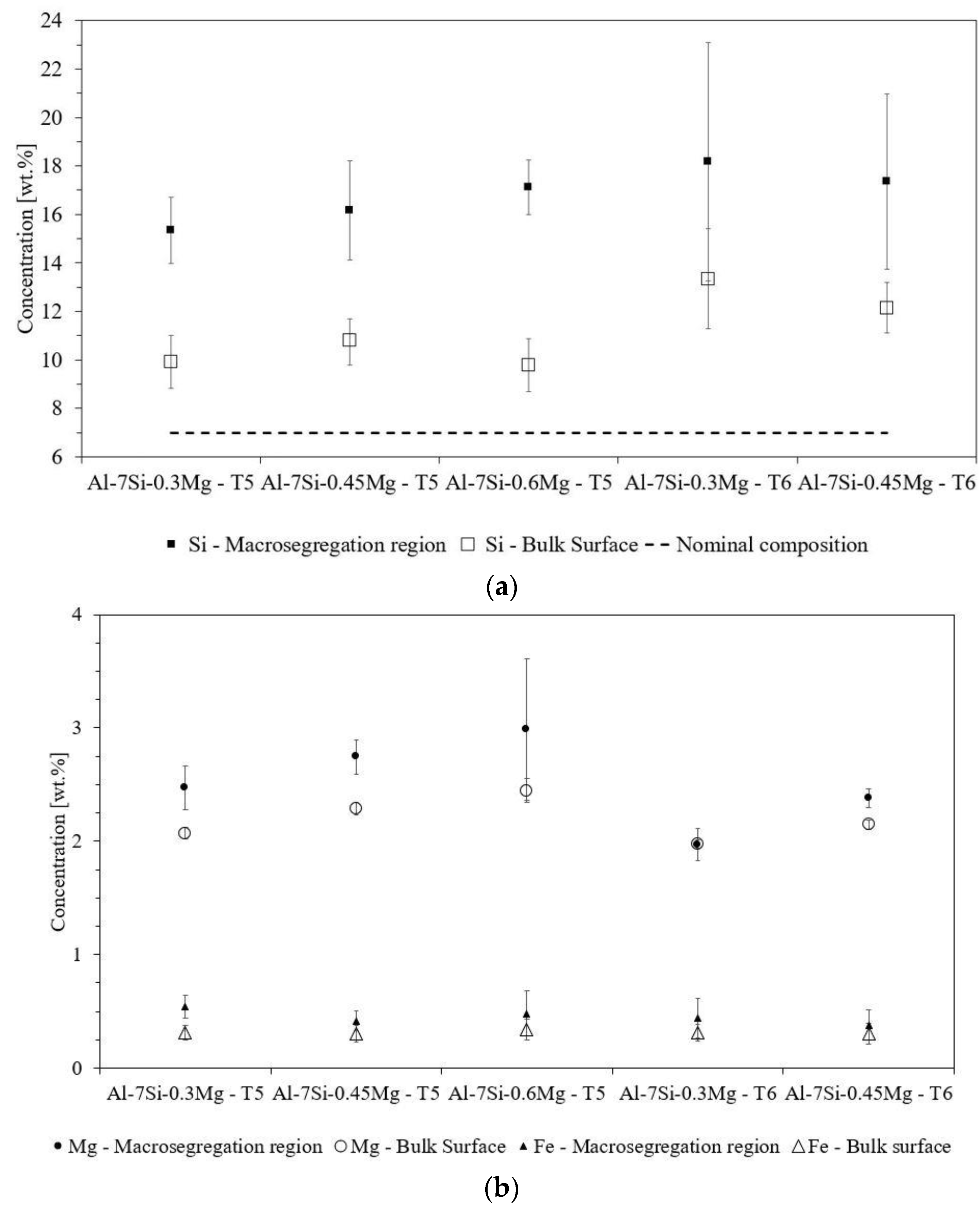
3.5. Fatigue Crack Initiation

In this study, the fatigue crack initiation occurred at the periphery of macrosegregation regions on 32 of a total of 54 SSM castings tested, as shown in Figure 6. Cold shots, less predominant than macrosegregation regions, were also harmful to fatigue properties, resulting in the fatigue crack initiation of 11 SSM castings tested. Figure 7 shows representative SEM micrographs of the defects at which fatigue crack initiation occurred in the SSM Al–7Si–Mg castings in the T5 and T6 conditions. The slurry flow direction in the die cavity was perpendicular to gravity. Therefore, there was better contact of the slurry with the bottom die wall compared to the top die wall during die cavity filling, which may have affected defect distribution. However, no trend was observed in the distribution of the defects, as seen in Table 2.
In most of the specimens tested, the fatigue crack was initiated at the periphery of the macrosegregation or cold shot located at the casting surface. The regions of macrosegregation had up to 200 µm thickness and a smooth surface when observed by SEM, as shown in Figure 7a,c. Additionally, the regions of macrosegregation often appeared surrounded by an oxide layer, as seen in Figure 7a,c. Therefore, it is likely that the bond between the regions of macrosegregation and the surrounding microstructure was weak. It is reasonable to assume that the oxide layer formed during anodising (around 3 µm thick in this study) had little or no effect on the fatigue life of SSM Al–7Si–Mg castings that contain large macrosegregation-related defects such as the ones observed in Figure 7.
Cold shots located at the casting surface also originated fatigue cracks in this study. These defects had a thickness significantly greater than the region of macrosegregation when observed on the fracture surface, as seen in Figure 7b. Similar to macrosegregation, the cold shots displayed a smooth surface, suggesting weak bonding between the defect and the surroundings, possibly due to an oxide layer covering the defect surface. A gap was observed between the cold shot and the surrounding fractured material, as shown in the highlighted image in Figure 7b. This gap, which may have widened during the fatigue testing, continued through the casting surface for a certain length, which revealed the weak bonding that existed between the defect and the surrounding material.
The microstructures of the macrosegregation and cold-shot regions that originated fatigue cracks in this study were obtained by polishing the casting surface where the defect was located. Figure 8a shows the microstructure observed after polishing the surface perpendicular to the fracture surface shown in Figure 7a. An almost fully eutectic microstructure was observed in the region of macrosegregation. In contrast, in the bulk surface, the microstructure consisted of few primary α1-Al globules, in-cavity solidified grains, and eutectic, as shown in Figure 8a. Additionally, evidence of oxide films located between the defect and the surroundings is highlighted by circles in Figure 8a. Lee et al. [15] found that macrosegregation decreased the fatigue life of magnesium high-pressure die castings. The microstructure of the regions of macrosegregation consisted of mostly eutectic [15], similar to this study.
Figure 8b shows the microstructure observed after polishing the surface perpendicular to the fracture surface shown in Figure 7b where the cold shot was located. Figure 8c shows the microstructure observed after polishing the fracture surface shown in Figure 7b. The red line observed in Figure 8b shows the approximate position of the perpendicular surface observed in Figure 8c. It seems that the gaps observed in Figure 8b,c divided a portion of material with a distinct microstructure (cold shot) compared to the surroundings. The microstructure of the cold shot contained a higher fraction of primary α1-Al globules and a lower fraction of in-cavity solidified grains compared to the surroundings, as shown in Figure 8c. The fraction of primary α1-Al globules in the cold-shot region and the surroundings was determined by the manual point count method from ASTM E562-11 [30]. A total of 0.44 ± 0.08 and 0.19 ± 0.03 primary α1-Al globules fractions were determined for the cold-shot region and surroundings, respectively. Note that these fractions of primary α1-Al globules include the growth of the primary α1-Al globules during solidification that occurs in the die cavity. The higher fraction of primary α1-Al globules in the cold-shot region suggests that this region was formed at an earlier stage of the SSM casting process than the surroundings. Additionally, there was evidence of oxides surrounding the cold shot, which indicates that it was exposed to air at some point during the casting process. Small globular grains can reach the maximum packing solid fraction point, and they exhibit a solid-like behaviour at solid fractions higher than 0.6 [38]. Therefore, it is unlikely that the agglomerate of α1-Al globules in the cold-shot region had a solid-like behaviour during die cavity filling.
An almost fully eutectic microstructure was observed in certain regions, filling the existing gap between the cold-shot region and the surroundings, as seen in Figure 8b. The bond between the cold shot and the surrounding microstructure was weak due to the gaps observed between the cold shot and the surroundings, as shown in Figure 8b,c. These weak bonds or gaps most likely resulted from the oxide films located in between the cold shot and the surrounding bulk surface. The distinct microstructure of the cold-shot region compared to the surroundings and the existing weak bonding between these regions due to the presence of oxides result in stress concentration regions in the material [35].
Figure 9 shows the microstructures of the regions of macrosegregation observed on the casting surface. The polishing procedure removed a layer of the casting surface of less than 190 µm in height. For the SSM castings in the T5 condition, the microstructure of the regions of macrosegregation consisted mostly of modified eutectic. In the T6 condition, a higher fraction of spheroidised eutectic silicon was observed in these regions of macrosegregation compared to the surroundings, as shown in Figure 9c. Occasionally either primary silicon or primary α-Al dendrites were also observed in the regions of macrosegregation. EDS measurements of silicon, magnesium, and iron concentrations in the regions of macrosegregation and surroundings of the SSM Al–7Si–Mg castings in both T5 and T6 conditions are shown in Figure 10. The SSM Al–7Si–0.4Mg castings were not analysed since they had similar microstructure and fatigue resistance to the SSM Al–7Si–0.45Mg castings. Both silicon and magnesium concentrations were significantly higher in the regions of macrosegregation than in the surroundings, particularly the silicon concentration. The iron concentration was slightly higher in the regions of macrosegregation compared to the surroundings in the SSM Al–7Si–0.3Mg casting in the T5 condition. However, no significant differences in iron concentration were found for the other castings, as shown in Figure 10b. For the SSM Al–7Si–Mg castings in the T6 condition, higher silicon concentrations were obtained in the surroundings of the regions of macrosegregation compared to the SSM castings with the same magnesium content in the T5 condition. However, it seems that the magnesium concentration tended to decrease further in both regions of macrosegregation and surroundings for the SSM Al–7Si–Mg castings in the T6 condition compared to the castings in the T5 condition.

4. Discussion

4.1. Fatigue Results

In four-point bending fatigue testing, the stress was at its maximum at the sample’s surface, which increased the significance of defects located at the casting surface and surface microstructure [39]. Both regions of macrosegregation and cold shots located at the casting surface were mostly found surrounded by oxides, resulting in weak bonding at the interfaces. Therefore, fatigue crack initiation was more likely to occur at the periphery of these defects, where the stresses were concentrated [3]. Murakami and Endo [40] showed that a small defect in a material could be analysed as a short crack that starts from the defect and stops propagating. Therefore, the defect projected area on a plane perpendicular to the direction of the maximum stress can be considered as the equivalent crack [40]. The maximum value of the stress intensity factor (Kl,max) along a small defect ( A r e a ≤ 1000 µm) periphery can be correlated to its projected area using the following equation [35]:
K l , m a x 0.65 σ 0 π A r e a
in which σ0 is the maximum principal stress in MPa, and the A r e a is the square root of the projected area of the defect in m. The Kl,max along the defect periphery that resulted in fatigue failure was calculated using Equation (2) for a series of SSM Al–7Si–Mg castings in the T5 and T6 conditions. The values of Kl,max varied between 1.3 to 3.6 MPa √m. Although cold shots were thicker than the macrosegregation regions (Figure 5) when observed on the fracture surface of the sample, it did not necessarily result in higher Kl,max for the cold shots. Therefore, macrosegregation can be as detrimental for fatigue life as cold shots.
In this study, the magnesium content and heat treatment conditions of the castings tested were varied. From the four-point bending fatigue results, there was not a clear trend showing the predominance of one or another defect with regard to stress level, heat treatment, or magnesium content of the casting, as shown in Figure 6.
Casting defects play a dominant role in fatigue, but the composition, microstructure, and heat treatment condition also affect fatigue properties [3]. The magnesium content and the heat treatment condition of the SSM castings influence not only the α-Al matrix strength but also the eutectic microstructure [3]. The increase in the α-Al strength reduces the number and size of local plastic deformation regions in the material during fatigue testing at a certain stress level [3]. Therefore, the formation of microcracks at the periphery of regions of macrosegregation and cold shots, stress concentration areas, is less likely for SSM castings with higher yield strength during fatigue testing. The strengthening of the α-Al matrix that results from precipitation hardening may be the reason for the higher fatigue life obtained for the SSM Al–7Si–0.3Mg castings in the T5 condition compared to the as-cast condition, as seen in Figure 6a.
The increase in the magnesium content of the SSM castings results in the strengthening of the α-Al matrix after ageing and a change in the eutectic microstructure [41]. The eutectic microstructure of the SSM Al–7Si–0.3Mg castings in the T5 condition consisted of modified eutectic silicon and plate-like π-Al8FeMg3Si6. The increase in the magnesium content of the SSM casting resulted in the formation of the Mg2Si phase, in addition to the π-Al8FeMg3Si6 phase, as shown in Figure 2d,f and Figure 4. Fatigue life seemed to increase with the increase in the magnesium content from 0.3 to 0.40 wt.% of the SSM castings in the T5 condition. This increase in the fatigue life most likely resulted from the higher strength of the α-Al phase of the SSM Al–7Si–0.40Mg casting in the T5 condition compared to the SSM Al–7Si–0.3Mg casting in the same condition. The increase in the magnesium content from 0.4 to 0.45 wt.% did not affect the fatigue life of the SSM castings in the T5 condition. When the magnesium content of the casting increased from 0.45 to 0.6 wt.%, the fatigue life tended to decrease slightly, as shown in Figure 6b. Wang et al. [3] also obtained a decrease in the fatigue life of Al–7Si–Mg sand castings when the magnesium content was increased from 0.4 to 0.7 wt.%. The increase in the magnesium content of castings increased the size of the brittle π-Al8FeMg3Si6 phase, in addition to enhancing precipitation hardening during ageing [36]. However, in the current study, the increase in the magnesium content of the SSM castings in the T5 conditions did not result in a larger π-Al8FeMg3Si6 phase being formed, as shown in Figure 4. It seems that a slightly higher fraction of Mg2Si was formed in the SSM Al–7Si–0.6Mg castings in the T5 condition than in the SSM castings with lower magnesium contents, as shown in Figure 4.
Figure 6a shows that fatigue life increased for the SSM Al–7Si–0.3Mg castings in the T6 condition compared to the T5 condition. The reduction in intermetallic phases fraction (Figure 4) and the larger space between eutectic silicon spheroids obtained after T6 heat treatment reduced dislocation interactions with the eutectic phases, which resulted in fewer microcracks being formed in the defect surroundings [3]. Additionally, the increase in α-Al strength minimised the number and area of the local plastic deformation regions in the casting during fatigue testing [3]. The increase in precipitation hardening that resulted from the increase in the magnesium content from 0.3 to 0.45 wt.% can explain the increase in the fatigue life of the SSM Al–7Si–0.45Mg casting in the T6 condition compared to that of the SSM Al–7Si–0.3Mg casting in the same condition, as shown in Figure 6c.

4.2. Defects Formation

In the die cavity, solidification occurs with the growth of the slurry α1-Al crystals and nucleation and growth of the in-cavity solidified crystals and eutectic. As the solidification progresses, the solute concentration in the remaining liquid increases until the conditions for eutectic reaction are reached. The cooling rate near the die wall is higher compared to the casting centre. As the surface layer of the casting shrinks, the solute-enriched liquid from the adjacent areas flows through the mushy zone towards the casting surface, i.e., by the inverse segregation mechanism [22]. Inverse segregation is enhanced by the intensification pressure applied that squeezes the central α1-Al globules to one another and forces the solute-enriched liquid that previously filled the α1-Al interdendritic spaces laterally towards the casting surface [22]. This solute-enriched liquid moved towards the casting surface and solidified into small, primary α-Al dendrites and eutectic, as described in other studies [17]. Figure 2 shows that the microstructure of the casting surface consisted of small, primary α-Al dendrites, eutectic, and a few slurry α1-Al globules. Additionally, the concentration of alloying elements in the surface layer of the casting was significantly higher compared to the nominal composition of the alloy which resulted from inverse segregation, as shown in Figure 10.
The nearly pure eutectic regions observed in Figure 9 resulted from the exudation mechanism, as observed in other studies [17,20,23,42]. Usually, inverse segregation is less severe than exudation [42]. Figure 10 shows that the concentration of alloying elements, particularly silicon, was much higher in the regions of macrosegregation compared to the adjacent areas of the surface layer of the castings. Oxide films were generally found surrounding the regions of macrosegregation, as shown in Figure 9. In this study, most of the fatigue cracks initiated at the periphery of the regions of macrosegregation where the bonding was very weak due to the presence of oxides at the interface. Figure 11 illustrates the different stages of the formation of the regions of macrosegregation based on the observations in this study and the literature [23,42,43,44].
At a certain moment during solidification in the die cavity, the solidifying surface layer of the alloy shrinks from the die wall due to solidification shrinkage and thermal contraction and, when it gains enough strength, pulls away from the die wall, forming a gap [23,42]. A pressure differential is generated between the air gap and the interior of the solidifying alloy [17,21]. The air gap between the solidifying alloy and the die wall is illustrated in Figure 11a. Lee et al. [23] found that the application of intensification pressure enhances the exudation mechanism. During the intensification pressure stage, the solute-enriched liquid can flow through the interdendritic channels and the oxide layer of the solidifying alloy into the space between the solidifying alloy and the die wall. However, the eutectic microstructure and the very high solute concentration of the regions of macrosegregation suggest that these regions are formed during the last stages of solidification during which the permeability of the interdendritic regions is very low. Therefore, at the last stages of solidification, the tensile strains generated due to the contraction of the solidifying surface layer [14] and intensification pressure can result in open hot tears through which the solute-enriched liquid can flow into the space between the solidifying layer and die wall. This mechanism may explain why the regions of macrosegregation appear as pools on the casting surface and not as a continuous layer on the casting surface, as shown in Figure 9.
After the solute-enriched liquid flows through the oxide layer into the space between the casting surface and die wall, it becomes exposed to air and, almost immediately, an oxide layer forms on its surface, as schematically shown in Figure 11b. Therefore, the regions of macrosegregation are often observed surrounded by oxide films, as shown in Figure 9. Oxide films located near the casting surface can also act as cracks through which solute-enriched liquid can flow and fill the space between the solidifying surface layer and the die wall. It is likely that, during intensification pressure, the existing air gap space between the solidifying alloy surface and the die wall decreases due to the increase in the internal pressure of the alloy. Therefore, the existing solute-enriched liquid in the space between the casting surface and the die wall is pressed against the die wall and solidifies, as shown in Figure 11c.
Figure 7b shows a defect observed on the fatigue fracture surface identified as a cold shot. This defect had a semi-elliptical shape, had an oxide layer, and solidified earlier than the adjacent regions, identical to the cold shots formed in HPDC. The fatigue cracks initiated at the periphery of the cold shot. The fraction of primary α1-Al globules in the cold-shot regions was higher (0.44 ± 0.08) than in the surroundings (0.19 ± 0.03). It is unlikely that the fraction of primary α1-Al globules in the cold shot was high enough to reach the maximum packing solid fraction point where the agglomerate of α1-Al globules behaves like a rigid solid [38]. The dimensionless Reynolds number is normally used to characterise the type of flow, laminar or turbulent, during die cavity filling [11]. The viscosity of slurries varies considerably depending on the α-Al crystal size, shape and fraction, and shear rate [45,46]. Therefore, it is difficult to determine the Reynolds number of slurries and, thereby, estimate the type of flow obtained during die cavity filling. However, even assuming that the flow type during die cavity filling is essentially laminar, the development of flow instabilities during die cavity filling is possible. These instabilities can result in a loose, solid network of α1-Al globules trapped near the casting surface by the surrounding solidifying alloy. This agglomerate of α1-Al globules was likely exposed to air at some stage of the die cavity filling to form the oxide layer on its surface, resulting in a weak bond with the adjacent regions, as shown in Figure 8b,c. In the last stages of solidification, the weak bonding between the defect and the surroundings can create a lower resistance path compared to the α-Al interdendritic regions for the flow of solute-enriched liquid towards the casting surface. Therefore, an almost fully eutectic region was observed between the defect and the surroundings, as shown in Figure 8b.

5. Conclusions

SSM Al–7Si–Mg castings in the as-cast, T5, and T6 condition were tested under four-point bending fatigue. Regions of positive macrosegregation at the casting surface were the most detrimental defects for fatigue in this study. The microstructure of the regions of macrosegregation was predominantly eutectic. These regions most likely formed in the last stages of solidification due to their higher silicon content compared to the bulk surface. An oxide layer was frequently found in the periphery of the regions of macrosegregation, which reduced the bonding between these regions and the bulk casting surface. Consequently, fatigue crack initiation occurred at the periphery of the regions of macrosegregation in most of the SSM castings. Cold shot was another defect that initiated fatigue crack in the SSM Al–7Si–Mg castings in this study. The cold shots were covered by an oxide layer that reduced the bonding with the surrounding microstructure, which resulted in fatigue crack initiation. The formation of a 3 μm thick oxide layer on the surface after anodising resulted in no effect on the fatigue life of the SSM Al–7Si–Mg castings, most likely due to the dominant effect of the macrosegregation regions formed near the castings’ surface on fatigue crack initiation.
The higher precipitation hardening response for the SSM Al–7Si–0.45Mg castings in the T5 and T6 condition compared to the SSM Al–7Si–0.3Mg castings in the same conditions resulted in higher fatigue resistance. However, the increase in the magnesium content of the alloy from 0.45 wt.% to 0.6 wt.% resulted in a slight decrease in the fatigue life of the SSM Al–Si–Mg castings in the T5 condition.

Author Contributions

Conceptualisation was divised from two adjoining activities with J.S. and A.E.W.J. from the casting side and B.Z. and C.Z. from the surface preparation side; methodology, J.S. and B.Z.; formal analysis, J.S. and B.Z.; investigation, J.S. and B.Z.; writing—original draft preparation, J.S. and B.Z.; writing—review and editing, all authors together; supervision, A.E.W.J. and C.Z.; project administration, A.E.W.J.; funding acquisition, A.E.W.J. and C.Z. All authors have read and agreed to the published version of the manuscript.

Funding

This work was funded by VINNOVA under the FatSS project (Dnr 2014-05096) and part of the LIGHTER programme, Knowledge Foundation (Dnr. 20100280) and Compcast Plus (Dnr. 20170066).

Institutional Review Board Statement

Not applicable.

Informed Consent Statement

Not applicable.

Data Availability Statement

In the current publication, all data are contained in the paper either as numbers or in graphical form.

Acknowledgments

The authors are also grateful for the support from Volvo Lastvagnar AB, COMPtech AB, and Fueltech AB in this research. The authors would like to thank Jacob Steggo for his assistance with fatigue testing and Peter Gunnarson for help with casting experiments.

Conflicts of Interest

The authors declare no conflict of interest. The funders had no role in the design of the study; in the collection, analyses, or interpretation of data; in the writing of the manuscript; or in the decision to publish the results.

References

  1. Krupp, U. Fatigue Crack Propagation in Metals and Alloys: Microstructural Aspects and Modelling Concepts; WILEY-VCH Verlag GmbH & Co. KGaA: Weinheim, Germany, 2007. [Google Scholar]
  2. Lados, D.; Apelian, D.; Paris, P.; Donald, J. Closure mechanisms in Al–Si–Mg cast alloys and long-crack to small-crack corrections. Int. J. Fatigue 2005, 27, 1463–1472. [Google Scholar] [CrossRef]
  3. Wang, Q.; Apelian, D.; Lados, D. Fatigue behavior of A356/357 aluminum cast alloys. Part II—Effect of microstructural constituents. J. Light Met. 2001, 1, 85–97. [Google Scholar] [CrossRef]
  4. Ammar, H.; Samuel, A.; Samuel, F. Effect of casting imperfections on the fatigue life of 319-F and A356-T6 Al–Si casting alloys. Mater. Sci. Eng. A 2008, 473, 65–75. [Google Scholar] [CrossRef]
  5. Tijani, Y.; Heinrietz, A.; Stets, W.; Voigt, P. Detection and Influence of Shrinkage Pores and Nonmetallic Inclusions on Fatigue Life of Cast Aluminum Alloys. Met. Mater. Trans. A 2013, 44, 5408–5415. [Google Scholar] [CrossRef]
  6. Dezecot, S.; Brochu, M. Microstructural characterization and high cycle fatigue behavior of investment cast A357 aluminum alloy. Int. J. Fatigue 2015, 77, 154–159. [Google Scholar] [CrossRef]
  7. Serrano-Munoz, I.; Buffiere, J.-Y.; Verdu, C. Casting defects in structural components: Are they all dangerous? A 3D Study. Int. J. Fatigue 2018, 117, 471–484. [Google Scholar] [CrossRef]
  8. Wang, Q.; Apelian, D.; Lados, D. Fatigue behavior of A356-T6 aluminum cast alloys. Part I. Effect of casting defects. J. Light Met. 2001, 1, 73–84. [Google Scholar] [CrossRef]
  9. Couper, M.J.; Neeson, A.E.; Griffiths, J.R. CASTING DEFECTS AND THE FATIGUE BEHAVIOUR OF AN ALUMINIUM CASTING ALLOY. Fatigue Fract. Eng. Mater. Struct. 1990, 13, 213–227. [Google Scholar] [CrossRef]
  10. Serrano-Munoz, I.; Buffiere, J.-Y.; Verdu, C.; Gaillard, Y.; Mu, P.; Nadot, Y. Influence of surface and internal casting defects on the fatigue behaviour of A357-T6 cast aluminium alloy. Int. J. Fatigue 2016, 82, 361–370. [Google Scholar] [CrossRef]
  11. Hu, X.; Zhu, Q.; Midson, S.; Atkinson, H.; Dong, H.; Zhang, F.; Kang, Y. Blistering in semi-solid die casting of aluminium alloys and its avoidance. Acta Mater. 2017, 124, 446–455. [Google Scholar] [CrossRef] [Green Version]
  12. Brochu, M.; Verreman, Y.; Ajersch, F.; Bouchard, D. High cycle fatigue strength of permanent mold and rheocast aluminum 357 alloy. Int. J. Fatigue 2010, 32, 1233–1242. [Google Scholar] [CrossRef] [Green Version]
  13. Brochu, M.; Verreman, Y.; Ajersch, F.; Bouchard, D. Propagation of short fatigue cracks in permanent and semi-solid mold 357 aluminum alloy. Int. J. Fatigue 2012, 36, 120–129. [Google Scholar] [CrossRef] [Green Version]
  14. Nadella, R.; Eskin, D.; Du, Q.; Katgerman, L. Macrosegregation in direct-chill casting of aluminium alloys. Prog. Mater. Sci. 2008, 53, 421–480. [Google Scholar] [CrossRef] [Green Version]
  15. Lee, S.; Patel, G.; Gokhale, A. Inverse surface macro-segregation in high-pressure die-cast AM60 magnesium alloy and its effects on fatigue behavior. Scr. Mater. 2005, 52, 1063–1068. [Google Scholar] [CrossRef]
  16. Otarawanna, S.; Gourlay, C.M.; Laukli, H.I.; Dahle, A.K. Microstructure Formation in AlSi4MgMn and AlMg5Si2Mn High-Pressure Die Castings. Met. Mater. Trans. A 2009, 40, 1645–1659. [Google Scholar] [CrossRef]
  17. Otarawanna, S.; Gourlay, C.; Laukli, H.; Dahle, A. Formation of the surface layer in hypoeutectic Al-alloy high-pressure die castings. Mater. Chem. Phys. 2011, 130, 251–258. [Google Scholar] [CrossRef]
  18. Payandeh, M.; Jarfors, A.E.; Wessen, M. Influence of Microstructural Inhomogeneity on Fracture Behaviour in SSM-HPDC Al-Si-Cu-Fe Component with Low Si Content. Solid State Phenom. 2014, 217–218, 67–74. [Google Scholar] [CrossRef] [Green Version]
  19. Eslami, M.; Payandeh, M.; Deflorian, F.; Jarfors, A.E.W.; Zanella, C. Effect of Segregation and Surface Condition on Corrosion of Rheo-HPDC Al–Si Alloys. Metals 2018, 8, 209. [Google Scholar] [CrossRef] [Green Version]
  20. Zhu, B.; Zanella, C. Hardness and corrosion behaviour of anodised Al-Si produced by rheocasting. Mater. Des. 2019, 173, 107764. [Google Scholar] [CrossRef]
  21. Gourlay, C.M.; Dahle, A.K.; Laukli, H.I. Segregation band formation in Al-Si die castings. Met. Mater. Trans. A 2004, 35, 2881–2891. [Google Scholar] [CrossRef]
  22. Gourlay, C.; Laukli, H.; Dahle, A. Defect Band Characteristics in Mg-Al and Al-Si High-Pressure Die Castings. Met. Mater. Trans. A 2007, 38, 1833–1844. [Google Scholar] [CrossRef]
  23. Lee, S.G.; Patel, G.; Gokhale, A. Characterization of the effects of process parameters on macrosegregation in a high-pressure die-cast Magnesium alloy. Mater. Charact. 2005, 55, 219–224. [Google Scholar] [CrossRef]
  24. Antoun, A.A.; Brochu, M.; Möller, H. Effect of the Rheocasting Process and of the SLS Layer on the Fatigue Behavior of 357 Aluminum Alloy. Solid State Phenom. 2014, 217–218, 227–234. [Google Scholar] [CrossRef]
  25. Cirik, E.; Genel, K. Effect of anodic oxidation on fatigue performance of 7075-T6 alloy. Surf. Coat. Technol. 2008, 202, 5190–5201. [Google Scholar] [CrossRef]
  26. Granath, O.; Wessén, M.; Cao, H. Determining effect of slurry process parameters on semisolid A356 alloy microstructures produced by RheoMetal process. Int. J. Cast Met. Res. 2008, 21, 349–356. [Google Scholar] [CrossRef]
  27. Santos, J.; Dahle, A.K.; Jarfors, A.E.W. Magnesium Solubility in Primary α-Al and Heat Treatment Response of Cast Al-7Si-Mg. Metals 2020, 10, 614. [Google Scholar] [CrossRef]
  28. SS-EN-ISO 6892-1:2016; Metallic Materials—Tensile Testing—Part 1: Method of Test at Room Temperature 2016. Swedish Institute for Standards: Stockholm, Sweden, 2016.
  29. Li, J.X.; Zhai, T.; Garratt, M.D.; Bray, G.H. Four-point-bend fatigue of AA 2026 aluminum alloys. Met. Mater. Trans. A 2005, 36, 2529–2539. [Google Scholar] [CrossRef]
  30. ASTM E562-11; Standard Test Method for Determining Volume Fraction by Systematic Manual Point Count. ASTM Int.: West Conshohocken, PA, USA, 2011; pp. 1–7. [CrossRef]
  31. Payandeh, M.; Jarfors, A.E.W.; Wessén, M. Solidification Sequence and Evolution of Microstructure during Rheocasting of Four Al-Si-Mg-Fe Alloys with Low Si Content. Met. Mater. Trans. A 2015, 47, 1215–1228. [Google Scholar] [CrossRef]
  32. Laukli, H.I.; Gourlay, C.M.; Dahle, A.K. Migration of crystals during the filling of semi-solid castings. Met. Mater. Trans. A 2005, 36, 805–818. [Google Scholar] [CrossRef]
  33. Law, M.; Hulme-Smith, C.N.; Matsushita, T.; Jönsson, P.G. Assessment of Mechanisms for Particle Migration in Semi-Solid High Pressure Die Cast Aluminium-Silicon Alloys. J. Manuf. Mater. Process. 2020, 4, 51. [Google Scholar] [CrossRef]
  34. Wang, Q.G.; Davidson, C.J. Solidification and precipitation behaviour of Al-Si-Mg casting alloys. J. Mater. Sci. 2001, 36, 739–750. [Google Scholar] [CrossRef]
  35. Murakami, Y. Effects of Small Defects and Nonmetallic Inclusions on the Fatigue Strength of Metals. JSME Int. J. Ser. A Mech. Mater. Eng. 1989, 32, 167–180. [Google Scholar] [CrossRef] [Green Version]
  36. Caceres, C.H.; Davidson, C.J.; Griffiths, J.R.; Wang, Q.G. The effect of Mg on the microstructure and mechanical behavior of Al-Si-Mg casting alloys. Met. Mater. Trans. A 1999, 30, 2611–2618. [Google Scholar] [CrossRef]
  37. Davidson, C.J.; Griffiths, J.R.; Zanada, A. Fatigue properties of a semi-solid cast Al-7Si-0.3Mg-T6 alloy. Metall. Sci. Tecnol. 2000, 18, 2. [Google Scholar]
  38. Dahle, A.; StJohn, D. Rheological behaviour of the mushy zone and its effect on the formation of casting defects during solidification. Acta Mater. 1998, 47, 31–41. [Google Scholar] [CrossRef]
  39. Strzelecki, P.; Tomaszewski, T. Analysis of axial load and bending load effects on the fatigue life. In AIP Conference Proceedings; AIP Publishing LLC.: Melville, NY, USA, 2018; Volume 2028, p. 20019. [Google Scholar] [CrossRef]
  40. Murakami, Y.; Endo, M. Effects of hardness and crack geometries on ΔKth of small cracks emanating from small defects. In The Behaviour of Short Fatigue Cracks; Mechanical Engineering Publications: London, UK, 1986; pp. 275–293. [Google Scholar]
  41. Chen, R.; Xu, Q.; Guo, H.; Xia, Z.; Wu, Q.; Liu, B. Correlation of solidification microstructure refining scale, Mg composition and heat treatment conditions with mechanical properties in Al-7Si-Mg cast aluminum alloys. Mater. Sci. Eng. A 2017, 685, 391–402. [Google Scholar] [CrossRef]
  42. Laukli, H.; Arnberg, L.; Lohne, O. Effects of grain refiner additions on the grain structures in HPDC A356 castings. Int. J. Cast Met. Res. 2005, 18, 65–72. [Google Scholar] [CrossRef]
  43. Kaempffer, F.; Weinberg, F. Macrosegregation in a copper alloy directionally cast with exudation of liquid. Met. Mater. Trans. A 1971, 2, 2477–2483. [Google Scholar] [CrossRef]
  44. Haug, E.; Mo, A.; Thevik, H.J. Macrosegregation near a cast surface caused by exudation and solidification shrinkage. Int. J. Heat Mass Transf. 1995, 38, 1553–1563. [Google Scholar] [CrossRef]
  45. Figueiredo, A.M.; Kato, A.; Flemings, M.C. Viscosity of Semi-Solid A357 Alloy in the Transient High Shear Rate Regime. Metall. Sci. Tecnol. 2000, 18, 32–36. Available online: http://www.fracturae.com/index.php/MST/article/view/988 (accessed on 2 May 2022).
  46. Chucheep, T.; Wannasin, J.; Canyook, R.; Rattanochaikul, T.; Janudom, S.; Wisutmethangoon, S.; Flemings, M.C. Characterization of Flow Behavior of Semi-Solid Slurries with Low Solid Fractions. Met. Mater. Trans. A 2013, 44, 4754–4763. [Google Scholar] [CrossRef]
Figure 1. (a) Illustration of the SSM casting and (b) dimensions in mm.
Metals 12 01061 g001
Figure 2. Optical micrographs from castings (cross-section centre and within the first 1 mm surface layer) of the different SSM Al–7Si–Mg castings, (a) Al–7Si–0.3Mg-T5 centre region, (b) Al–7Si–0.3Mg-T5 surface layer, (c) Al–7Si–0.45Mg-T5 centre region, (d) Al–7Si–0.45Mg-T5 surface layer, (e) Al–7Si–0.6Mg-T5 centre region, (f) Al–7Si–0.6Mg-T5 surface layer, (g) Al–7Si–0.3Mg-T6 centre region, (h) Al–7Si–0.3Mg-T6 surface layer, (i) Al–7Si–0. 45Mg-T6 centre region and (j) Al–7Si–0. 45Mg-T6 surface layer.
Metals 12 01061 g002
Figure 3. SEM images showing the eutectic microstructure of the surface layer of the (a) SSM Al–7Si–0.3Mg—T5, (b) SSM Al–7Si–0.45Mg—T5, (c) SSM Al–7Si–0.6Mg—T5, (d) SSM Al–7Si–0.3Mg—T6, and (e) SSM Al–7Si–0.45Mg—T6 castings.
Metals 12 01061 g003
Figure 4. (a) Average length of β-Al5FeSi and π-Al8FeMg3Si6 phases. (b) Area fraction of the intermetallic phases detected in the SSM castings. Error bars show the standard error of the measurements.
Metals 12 01061 g004
Figure 5. Tensile testing results of the SSM Al–7Si–Mg castings in the different conditions. Error bars show the standard deviation of the measurements.
Metals 12 01061 g005
Figure 6. SN curves with all experiments shown and the cause of failure identified on individual sample level of (a) SSM Al–7Si–0.3Mg castings in the as-cast, T5, and T6 conditions and SSM Al–7Si–Mg castings with varying magnesium contents in the (b) T5 and (c) T6 conditions. (d) SN curve obtained for the SSM Al–7Si–0.4Mg castings in the T5 condition with and without anodising.
Metals 12 01061 g006
Figure 7. T-SEM micrographs showing the fracture surface of the (a) SSM Al–7Si–0.45Mg casting in the T5 condition, (b) SSM Al–7Si–0.6Mg casting in the T5, and (c) SSM Al–7Si–0.3Mg casting in the T6 conditions. The dashed line shows the casting surface position in the image.
Metals 12 01061 g007aMetals 12 01061 g007b
Figure 8. Microstructure of the crack initiation region on the surface perpendicular to the fracture surface of (a) SSM Al–7Si–0.45Mg in the T5 condition and (b) SSM Al–7Si–0.6Mg casting in the T5 condition after fatigue testing at σ = ±158 MPa. (c) The microstructure of the surface perpendicular to (b) after polishing. The full line shows the fracture surface location in the images. The red line shows the position of the casting surface observed in (b). The circles highlight some regions of no bonding.
Metals 12 01061 g008
Figure 9. Optical micrographs showing regions of macrosegregation on the first 190 µm surface layer of (a) SSM Al–7Si–0.3Mg and (b) SSM Al–7Si–0.6Mg castings in the T5 condition and (c) SSM Al–7Si–0.45Mg casting in the T6 condition. 1—Region of positive macrosegregation. Arrows indicate the possible location of oxide films. The dashed line shows the die wall position during casting.
Metals 12 01061 g009aMetals 12 01061 g009b
Figure 10. Concentrations of elements in the regions of macrosegregation and bulk surface measured by EDS: (a) silicon and (b) magnesium and iron. The horizontal, dashed line in (a) indicates the silicon nominal composition of the alloys.
Metals 12 01061 g010
Figure 11. Illustration of the longitudinal section of the alloy surface layer during: (a) formation of an air gap between die wall and partially solidified alloy due to solidification shrinkage and thermal contraction. (b) The solute-enriched liquid can flow through interdendritic channels or open, hot tears into the existing space between the solidifying layer and the die wall. (c) The solute-enriched liquid.
Metals 12 01061 g011
Table 1. Average chemical compositions of the Al–7Si–Mg alloys used in this study. Compositions in wt.%.
AlloysSiMgFeTiSrAl
Al–7Si–0.3Mg7.0 ± 0.10.32 ± 0.040.14 ± 0.020.09 ± 0.020.020 ± 0.011Bal.
Al–7Si–0.4Mg7.2 ± 0.10.41 ± 0.020.12 ± 0.010.11 ± 0.01 0.029 ± 0.001Bal.
Al–7Si–0.45Mg7.4 ± 0.20.47 ± 0.010.11 ± 0.010.11 ± 0.010.025 ± 0.002Bal.
Al–7Si–0.6Mg7.1 ± 0.10.60 (0.04)0.12 ± 0.010.12 ± 0.010.024 ± 0.002Bal.
Table 2. Number of defects that initiated fatigue crack and distribution as a function of the casting surface position during die cavity filling.
DefectCasting Surface Position during Die Cavity Filling
Top dieBottom die
Macrosegregation1616
Cold shot56
Publisher’s Note: MDPI stays neutral with regard to jurisdictional claims in published maps and institutional affiliations.

