
The Effect of TiC and Zr Additions on the Microstructure and Mechanical Properties of Ti-30Mo Alloy


Abstract
:1. Introduction
2. Experimental Procedure
2.1. Material Preparation
2.2. Characterization
3. Results and Discussion
3.1. Analysis of Microstructure and Mechanical Properties of Ti-30Mo-nTiC Alloys
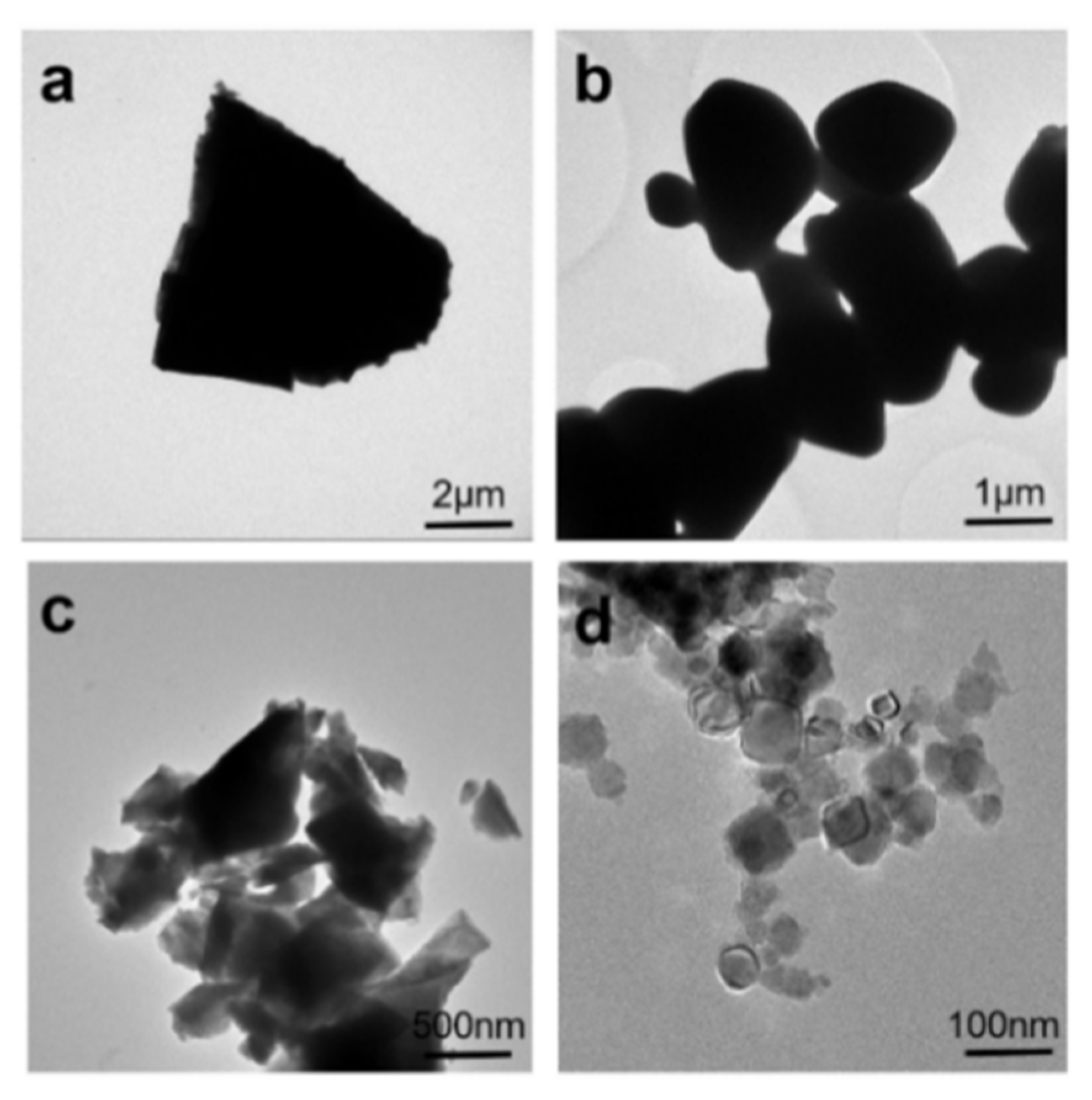
3.1.1. Microstructure Analysis
3.1.2. Mechanical Properties Analysis
3.2. Analysis of Microstructure and Mechanical Properties of Ti-30Mo-0.5TiC-xZr Alloys
3.2.1. Microstructure Analysis
3.2.2. Analysis of Room Temperature Mechanical Properties
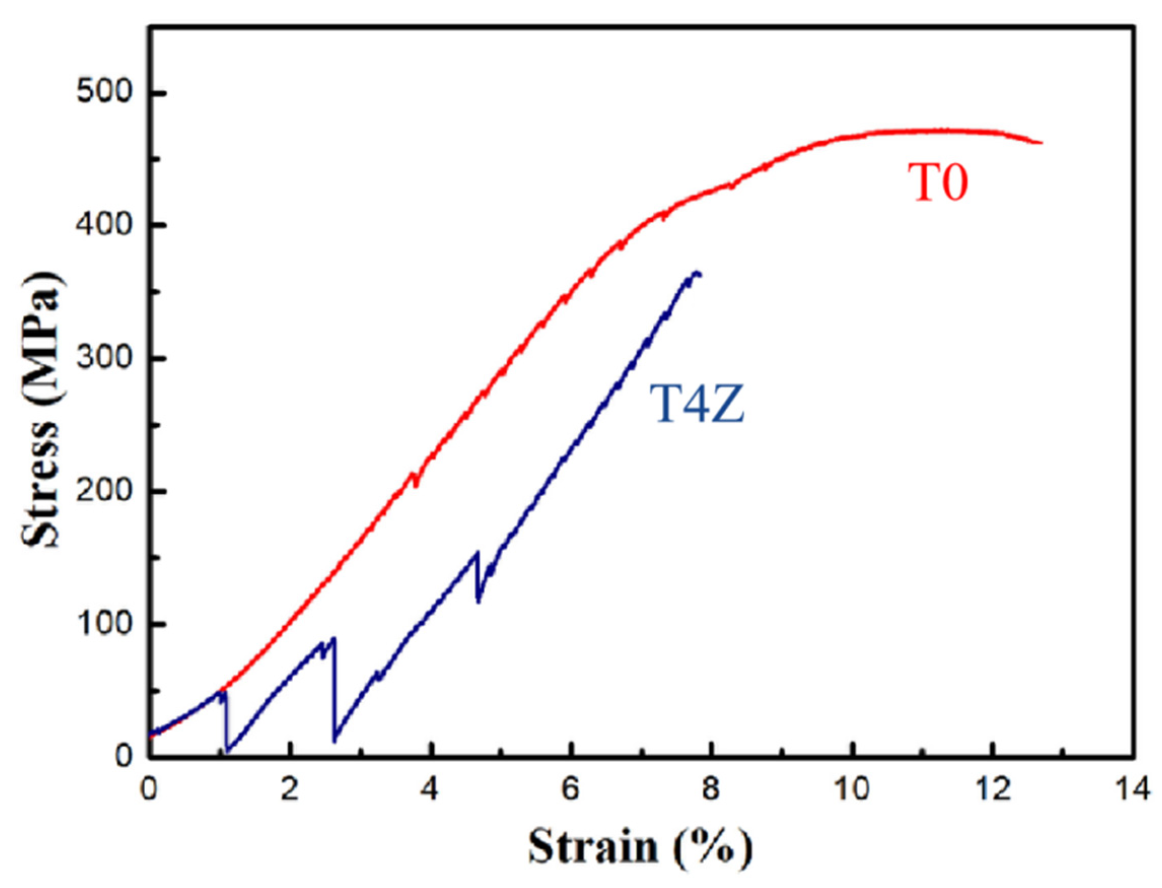
3.2.3. High Temperature Tensile Properties and Fracture Model at 600 °C
4. Conclusions
- The diffusion and particle strengthening effect of TiC with the addition of 0.5 wt.% TiC to Ti-30Mo significantly increased the relative density of the alloy, while its elastic modulus increased from 84 GPa to 112 GPa and tensile strength increased from 654 MPa to 825 MPa. Meanwhile, the microhardness and elongation of Ti-30Mo-0.5TiC alloy were 291 HV0.3 and 7.3%, respectively.
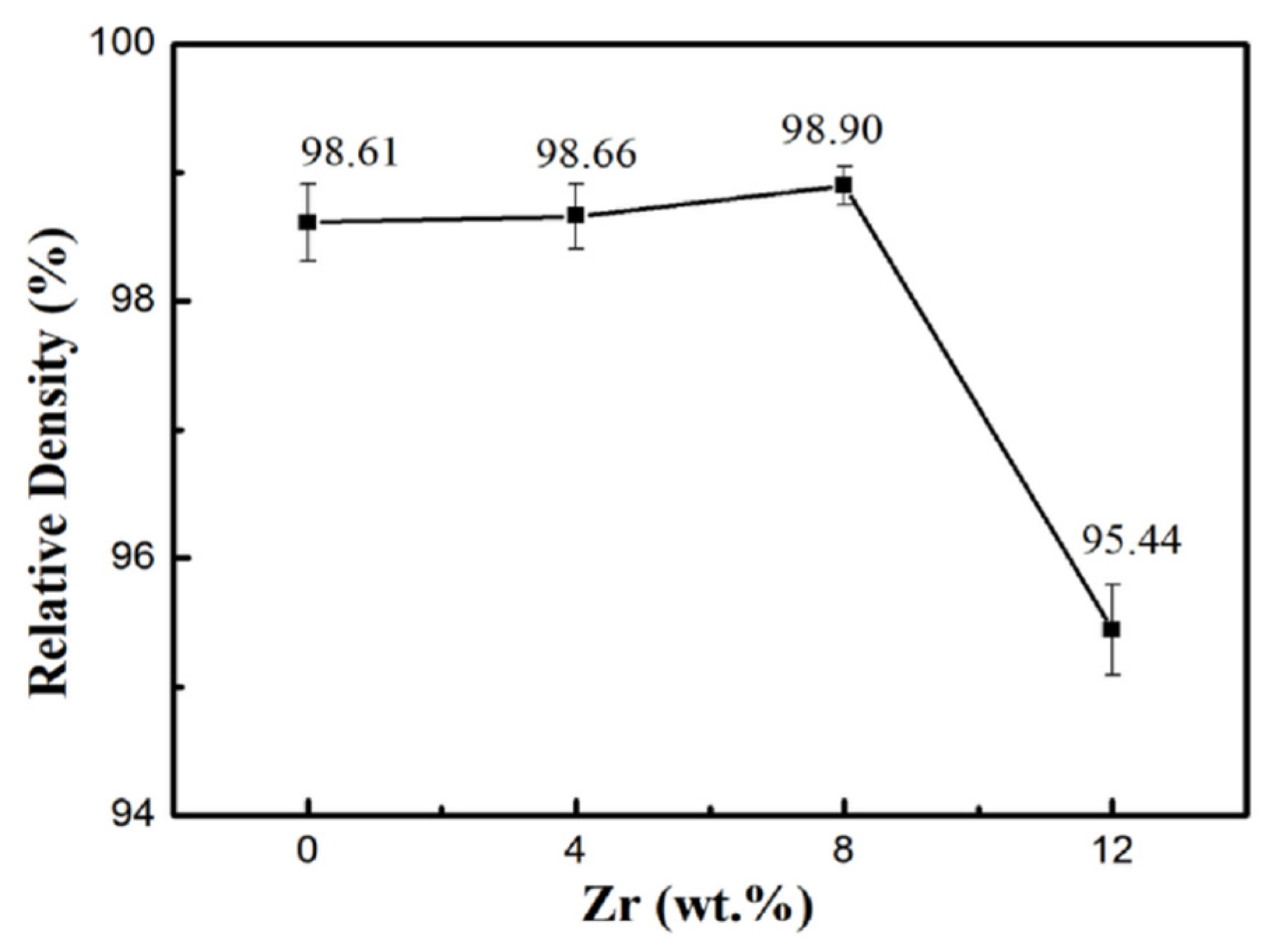
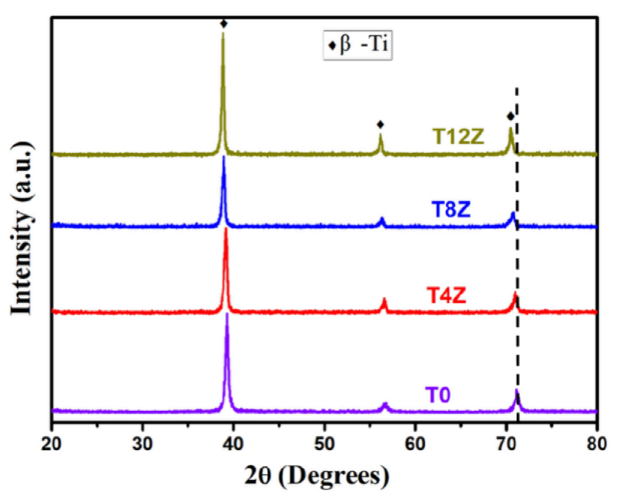
- The β-phase lattice constant of Ti-30Mo-0.5TiC-xZr alloys increased with the increase of Zr content. This led to an increased amount of carbide particle aggregation, decreasing the tensile strength and elongation of the alloys.
- During high-temperature tensile testing at 600 °C, both Ti-30Mo-0.5TiC and Ti-30Mo-0.5TiC-4Zr alloys exhibited a distinct ductility fracture pattern, but Ti-30Mo-0.5TiC had superior high-temperature properties with a tensile strength and elongation of 472 MPa and 12.8%, respectively.
Author Contributions
Funding
Institutional Review Board Statement
Informed Consent Statement
Acknowledgments
Conflicts of Interest
References
- Zhang, W.; Yang, P.; Cao, Y.; Li, X.; Wei, D.; Kato, H.; Wu, Z. New Ti/β-Ti alloy laminated composite processed by powder metallurgy: Microstructural evolution and mechanical property. Mater. Sci. Eng. A 2021, 822, 141702. [Google Scholar] [CrossRef]
- Zheng, Z.; Chai, L.; Xiang, K.; Huang, W.; Wang, Y.; Liu, L.; Tian, L. Typical Microstructural Characteristics of Ti-5Al-5Mo-5V-3Cr-1Fe Metastable β Ti Alloy Forged in α + β Region. Acta Metall. Sin. (Engl. Lett.) 2020, 33, 1601–1608. [Google Scholar] [CrossRef]
- Rominiyi, A.L.; Shongwe, M.B.; Jeje, S.O.; Olubambi, P.A. Microstructure, tribological and oxidation behaviour of spark plasma sintered Ti-Ni-xTiCN composites. J. Alloys Compd. 2021, 890, 161857. [Google Scholar] [CrossRef]
- Xie, L.; Zhou, W.; Zou, S. Pitting behavior of Ti-15-3 titanium alloy with different surface in salt spray studied using electrochemical noise. J. Mater. Res. Technol. 2021, 14, 2865–2883. [Google Scholar] [CrossRef]
- Sakaguchi, S.; Nakahara, K.; Hayashi, Y. Development of sintered Ti-30mass%Mo alloy and its corrosion properties. Met. Mater. 1999, 5, 193–195. [Google Scholar] [CrossRef]
- Dingrong, Q. Studies on the Structure and Performance of Ti32Mo Alloy Passive Film Formed in HCl Solution; Beijing University of Chemical Technology: Beijing, China, 2001. [Google Scholar]
- Zhao, X.; Niinomi, M.; Nakai, M.; Hieda, J. Beta type Ti-Mo alloys with changeable Young’s modulus for spinal fixation applications. Acta. Biomaterialia 2012, 8, 1990–1997. [Google Scholar] [CrossRef]
- Peillon, N.; Fruhauf, J.B.; Gourdet, S.; Feraille, J.; Saunier, S.; Desrayaud, C. Effect of TiH2 in the preparation of MMC Ti based with TiC reinforcement. J. Alloys Compd. 2015, 619, 157–164. [Google Scholar] [CrossRef]
- Zhang, H.; Niu, H.; Zang, M.; Yue, J.; Zhang, D. Microstructures and mechanical behavior of a near α titanium alloy prepared by TiH2-based powder metallurgy. J. Mater. Sci. Eng. A 2020, 770, 138570. [Google Scholar] [CrossRef]
- Chen, T.; Yang, C.; Liu, Z.; Ma, H.; Kang, L.; Wang, Z.; Zhang, W.; Li, D.; Li, N.; Li, Y. Revealing dehydrogenation effect and resultant densification mechanism during pressureless sintering of TiH2 powder. J. Alloys Compd. 2021, 873, 159792. [Google Scholar] [CrossRef]
- Xing, Z.; Mingxing, Z.; Dake, X.; Geng, S.; Wang, Q.; Wang, F. Microstructural evolution, corrosion behavior and cytotoxicity of Ti-6Al-4V/ZrO2 composite fabricated by directed energy deposition for implant biomaterial. J. Alloys Compd. 2021, 892, 161820. [Google Scholar]
- Wang, L.; Yang, L.; Huang, Y.; Yuan, Y.; Jia, C. Effects of Y2O3 addition on the microstructure and wear-resistant performance of TiN/TiB-reinforced Ti-based laser-clad coatings on Ti-6Al-4V alloys. Mater. Today Commun. 2021, 29, 120752. [Google Scholar] [CrossRef]
- Pan, L.; Song, K.; Gu, J.; Qiu, T.; Yang, J. Microstructure and Mechanical Properties of (TiB2 + SiC) Reinforced Ti3SiC2 Composites Synthesized by In Situ Hot Pressing. Int. J. Appl. Ceram. Technol. 2016, 13, 629–635. [Google Scholar] [CrossRef]
- Cao, Y.; Zeng, F.; Lu, J.; Liu, B.; Liu, Y.; Li, Y. In Situ Synthesis of TiB/Ti6Al4V Composites Reinforced with Nano TiB through SPS. Mater. Trans. 2015, 56, 259–263. [Google Scholar] [CrossRef] [Green Version]
- Rastegari, H.A.; Asgari, S.; Abbasi, S.M. Producing Ti-6Al-4V/TiC composite with good ductility by vacuum induction melting furnace and hot rolling process. Mater. Des. 2011, 32, 5010–5014. [Google Scholar] [CrossRef]
- Ali, T.; Wang, L.; Cheng, X.; Gu, D.; Zhou, Z.; Min, X. The effect of TiC on microstructure and mechanical properties of Ti-5553 beta phase titanium alloy. Mater. Des. 2022, 214, 110395. [Google Scholar] [CrossRef]
- Xu, S.; Zhou, C.; Liu, Y.; Liu, B.; Li, K. Microstructure and mechanical properties of Ti-15Mo-xTiC composites fabricated by in-situ reactive sintering and hot swaging. J. Alloys Compd. 2018, 738, 188–196. [Google Scholar] [CrossRef]
- Xiong, Y.; Du, M.; Zhang, F.; Sabab, F.; Shanga, C. Preparation and mechanical properties of titanium alloy matrix composites reinforced by Ti3AlC and TiC ceramic particulates. J. Alloys Compd. 2021, 886, 161216. [Google Scholar] [CrossRef]
- Xia, C.; Zhang, Z.; Feng, Z.; Pan, B.; Zhang, X.; Ma, M.; Liu, R. Effect of zirconium content on the microstructure and corrosion behavior of Ti-6Al-4V-xZr alloys. Corros. Sci. 2016, 112, 687–695. [Google Scholar] [CrossRef]
- Qian, B.; Zhang, J.; Fu, Y.; Sun, F.; Wu, Y.; Cheng, J.; Vermaut, P.; Prima, F. In-situ microstructural investigations of the TRIP-to-TWIP evolution in Ti-Mo-Zr alloys as a function of Zr concentration. J. Mater. Sci. Technol. 2021, 65, 228–237. [Google Scholar] [CrossRef]
- Guanfang, C. Deformation Mechanism of New TRIP/TWIP Ti-Mo-Zr Alloys with High Strength and Ductility; China University of Mining and Technology: Beijing, China, 2019. [Google Scholar]
- Kumar, P.; Chandran, K. Enhancement of fatigue resistance using the accelerated diffusion/sintering phenomenon near beta transus temperature in Ti-6Al-4V powder metallurgy alloy. Scr. Mater. 2019, 165, 1–5. [Google Scholar] [CrossRef]
- Massalski, I.; Thaddeus, B. Binary Alloy Phase Diagrams; American Society for Metals: Metals Park, OH, USA, 1986. [Google Scholar]
- Jiao, Y.; Huang, L.; Lin, G. Progress on discontinuously reinforced titanium matrix composites. J. Alloys Compd. 2018, 767, 1196–1215. [Google Scholar] [CrossRef]
- Yan, Q.D.; Yu, J.; Lin, X.; Dang, M.J.; Shi, S.Q.; Zhang, Y.F.; Huang, W.D. High strength in-situ beta reinforced Ti-based bulk metallic glass composite produced by laser Powder Bed Fusion using elemental powder mixture. Mater. Sci. Eng. A 2022, 833, 142559. [Google Scholar] [CrossRef]
- Mohan, P.; Rajak, D.K.; Pruncu, C.I.; Behera, A.; Amigó-Borrás, V. Influence of β-phase stability in elemental blended Ti-Mo and Ti-Mo-Zr alloys. Micron 2020, 142, 102992. [Google Scholar] [CrossRef] [PubMed]
- Min, X.; Emura, S.; Meng, F.; Mi, G.; Tsuchiya, K. Mechanical twinning and dislocation slip multilayered deformation microstructures in β-type Ti-Mo base alloy. Scr. Mater. 2015, 102, 79–82. [Google Scholar] [CrossRef]
- Chen, W.; Yu, G.; Li, K.; Wang, Y.; Zhang, J.; Sun, J. Plastic instability in Ti-6Cr-5Mo-5V-4Al metastable β-Ti alloy containing the β-spinodal decomposition structures. Mater. Sci. Eng. A 2021, 811, 141052. [Google Scholar] [CrossRef]


| Alloys | Density (g/cm3) | Relative Density (%) | Porosity (%) |
|---|---|---|---|
| Ti-30Mo | 4.88 ± 0.02 | 91.2 ± 0.4 | 11 ± 0.3 |
| Ti-30Mo-0.5TiC | 5.34 ± 0.01 | 98.3 ± 0.2 | 0.3 ± 0.1 |
| Alloys | HV0.3 | Young’s Modulus (GPa) | Ultimate Tensile Strength (MPa) | Elongation (%) |
|---|---|---|---|---|
| Ti-30Mo | 152 ± 11 | 84 ± 2 | 654 ± 27 | 3.8 ± 0.4 |
| Ti-30Mo-0.5TiC | 291 ± 4 | 112 ± 1 | 825 ± 12 | 7.3 ± 0.2 |
| Alloys | Areas | Elements (at. %) | |||
|---|---|---|---|---|---|
| Ti | Mo | C | Zr | ||
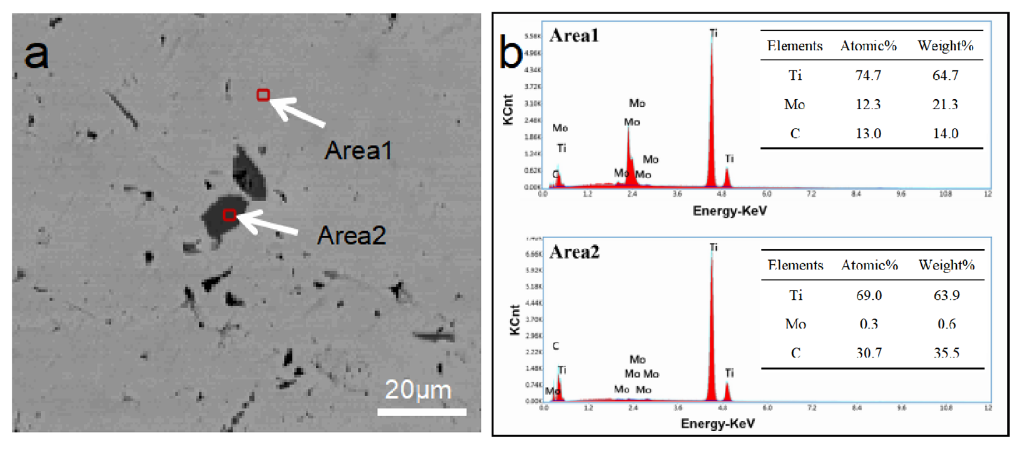
| T0 | Area1 | 74.7 | 12.3 | 13.0 | - |
| Area2 | 69.0 | 0.3 | 30.7 | - | |
| T4Z | Area1 | 71.1 | 12.6 | 14.2 | 2.1 |
| Area2 | 66.3 | 0.2 | 31.8 | 1.7 | |
| T8Z | Area1 | 66.7 | 12.1 | 17.7 | 3.5 |
| Area2 | 64.4 | 0.3 | 32.1 | 3.2 | |
| T12Z | Area1 | 58.8 | 11.4 | 24.5 | 5.3 |
| Area2 | 52.3 | 0.3 | 32.5 | 4.9 | |
Publisher’s Note: MDPI stays neutral with regard to jurisdictional claims in published maps and institutional affiliations. |
© 2022 by the authors. Licensee MDPI, Basel, Switzerland. This article is an open access article distributed under the terms and conditions of the Creative Commons Attribution (CC BY) license (https://creativecommons.org/licenses/by/4.0/).
Share and Cite
Wang, Z.; Cheng, H.; Liu, B.; Zhang, X.; Liu, Z. The Effect of TiC and Zr Additions on the Microstructure and Mechanical Properties of Ti-30Mo Alloy. Metals 2022, 12, 1025. https://doi.org/10.3390/met12061025
Wang Z, Cheng H, Liu B, Zhang X, Liu Z. The Effect of TiC and Zr Additions on the Microstructure and Mechanical Properties of Ti-30Mo Alloy. Metals. 2022; 12(6):1025. https://doi.org/10.3390/met12061025
Chicago/Turabian StyleWang, Zhenwei, Huichao Cheng, Bin Liu, Xin Zhang, and Zhanggen Liu. 2022. "The Effect of TiC and Zr Additions on the Microstructure and Mechanical Properties of Ti-30Mo Alloy" Metals 12, no. 6: 1025. https://doi.org/10.3390/met12061025