
Face Bend Property of 7N01-T4 Aluminum Alloy MIG Welded Joint by Using Different Welding Wires

Abstract
:1. Introduction
2. Experimental Materials and Methods
2.1. Experimental Materials
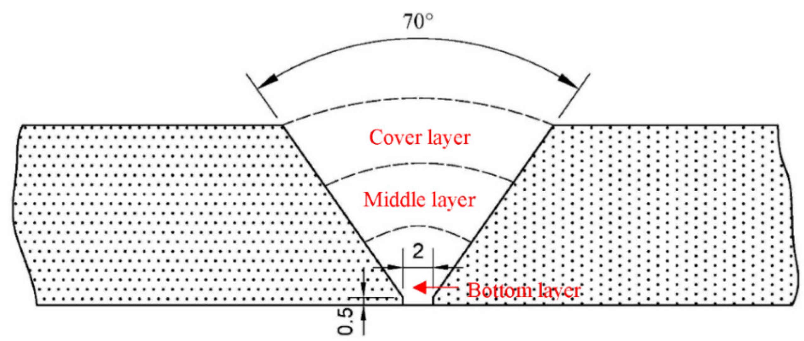
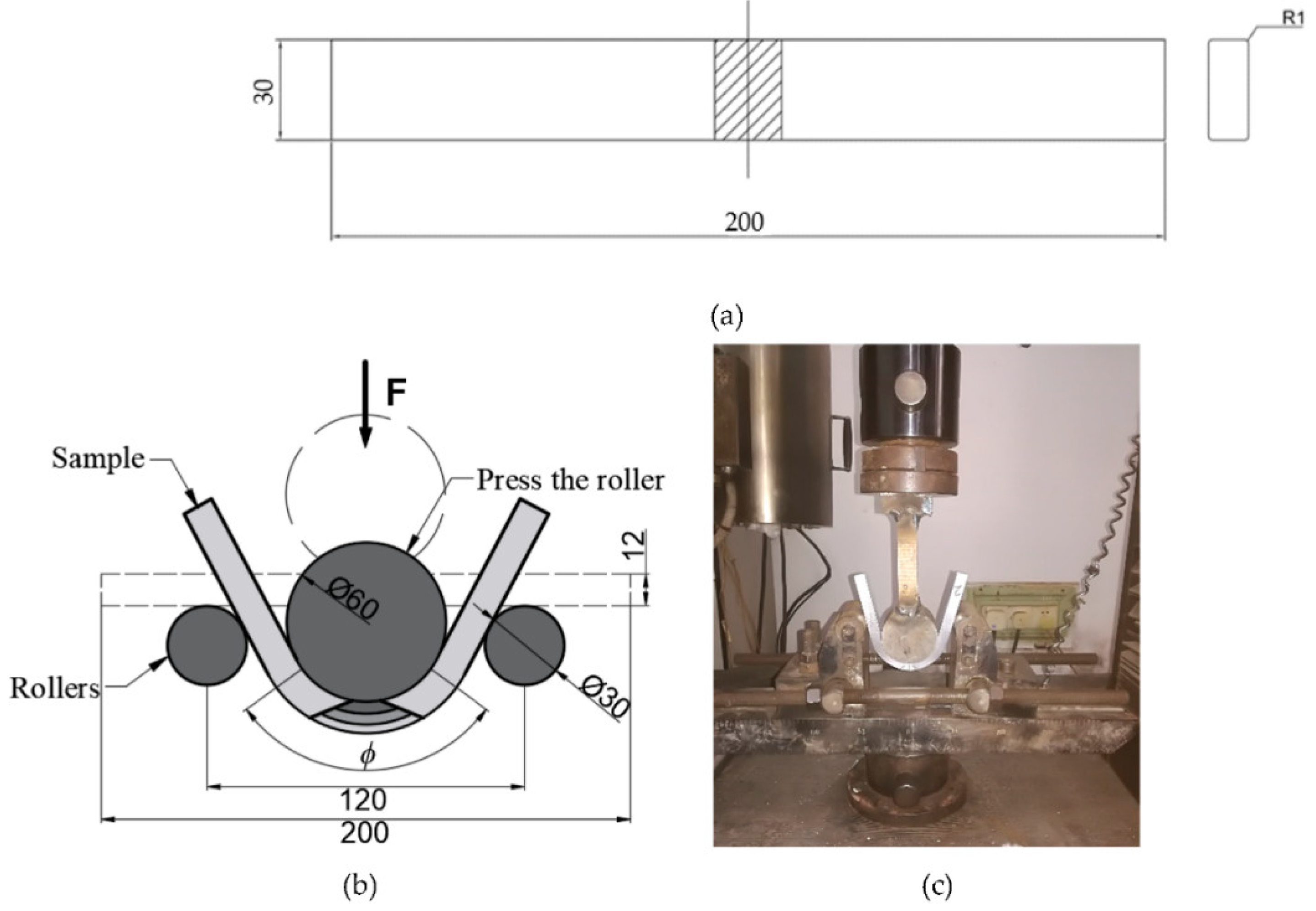
2.2. Experimental Methods
3. Results and Discussion
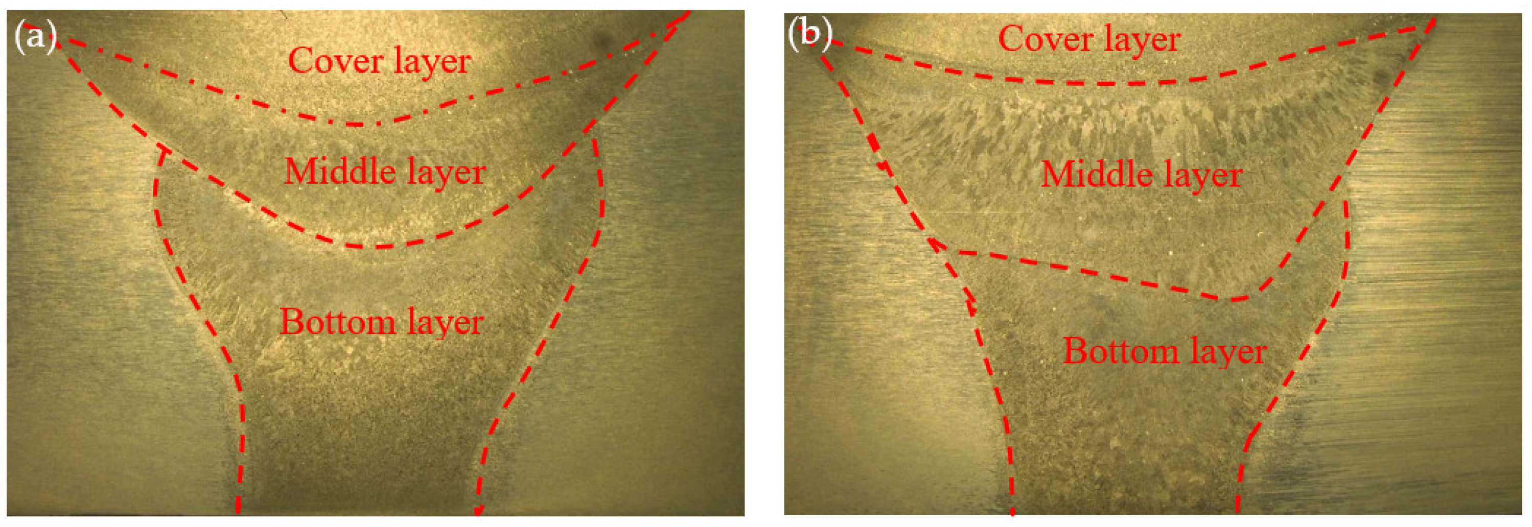
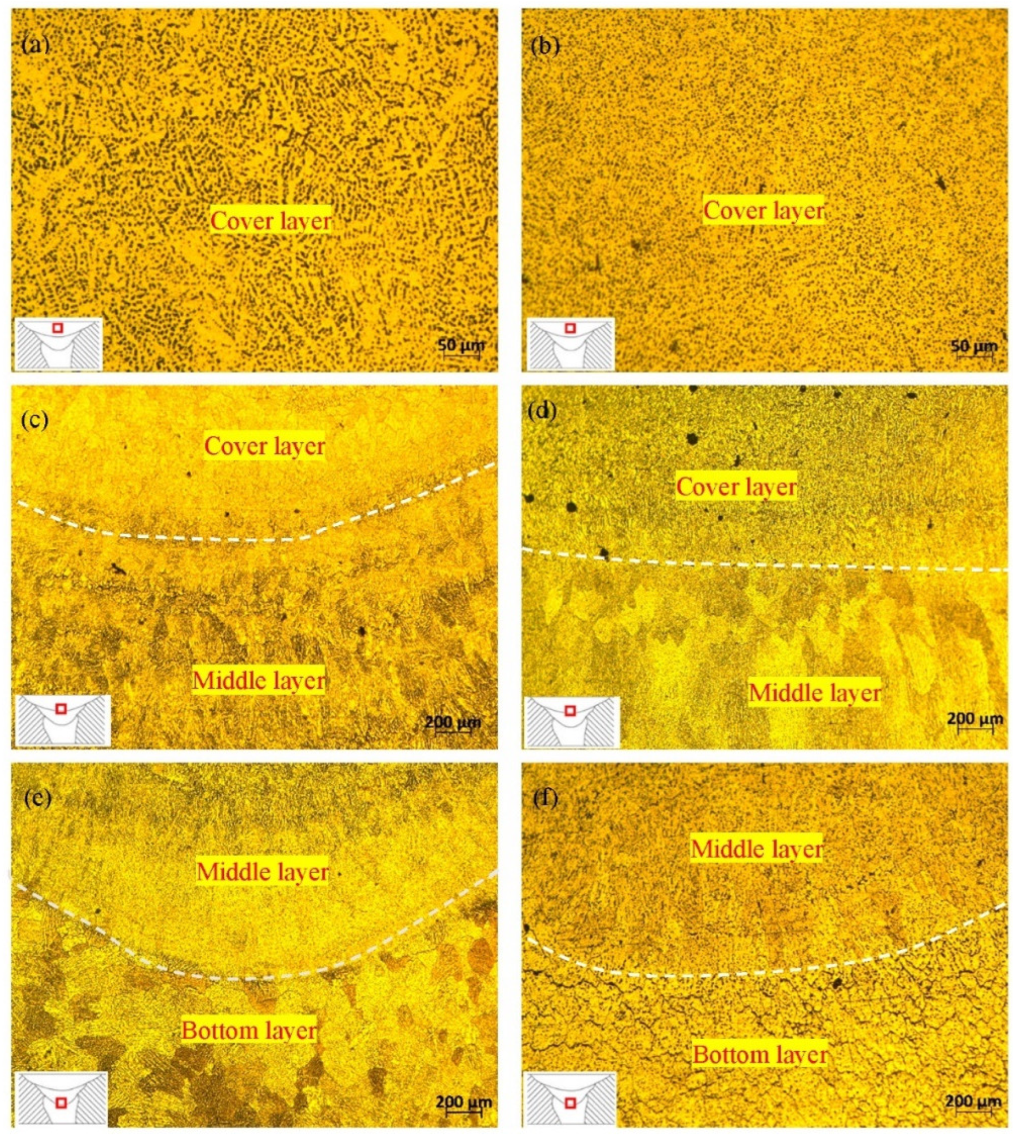
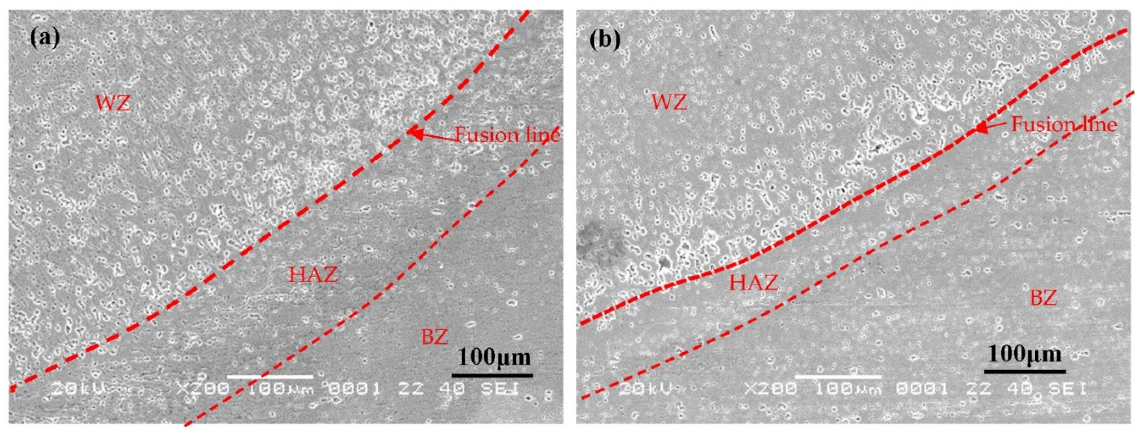
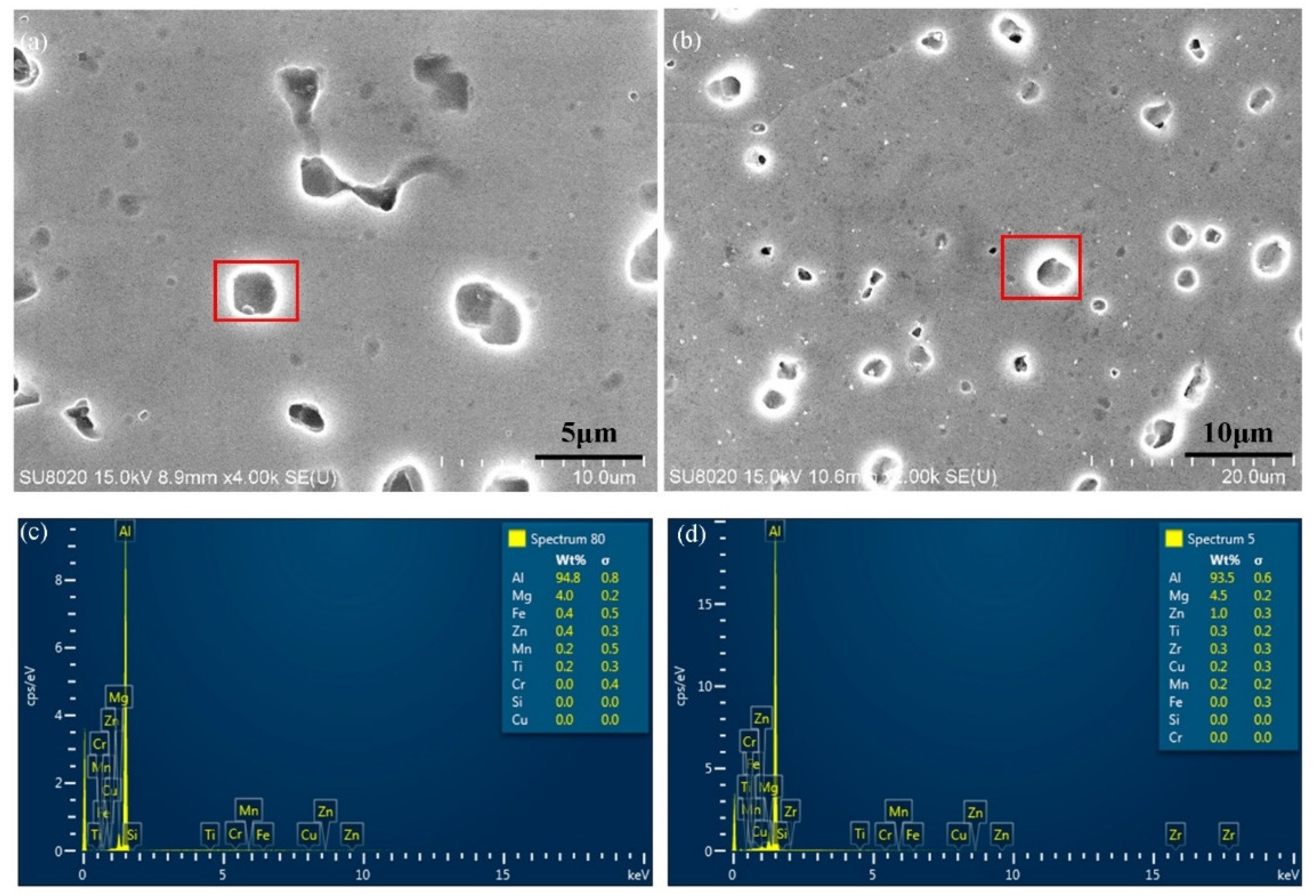
3.1. Microstructure
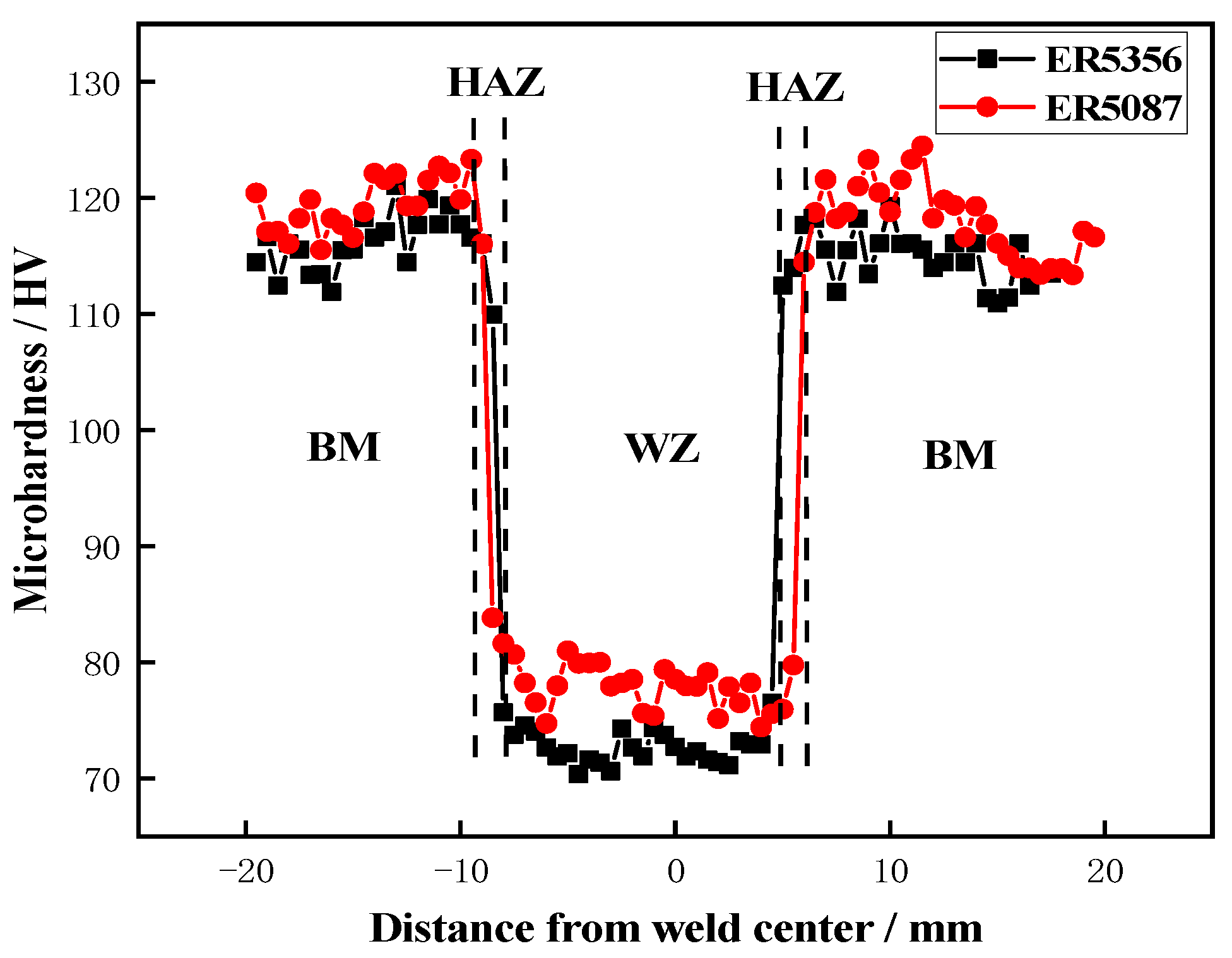
3.2. Microhardness
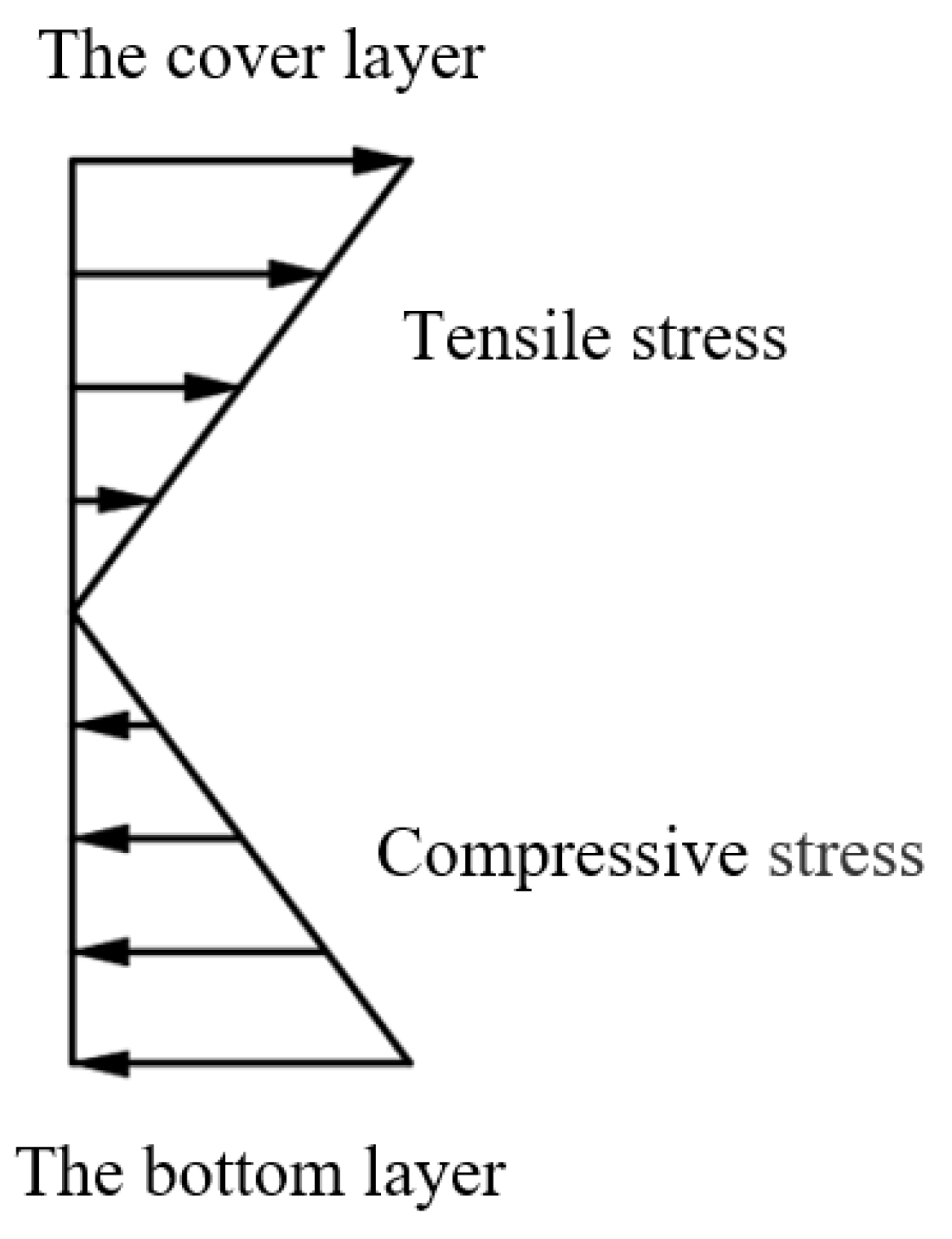
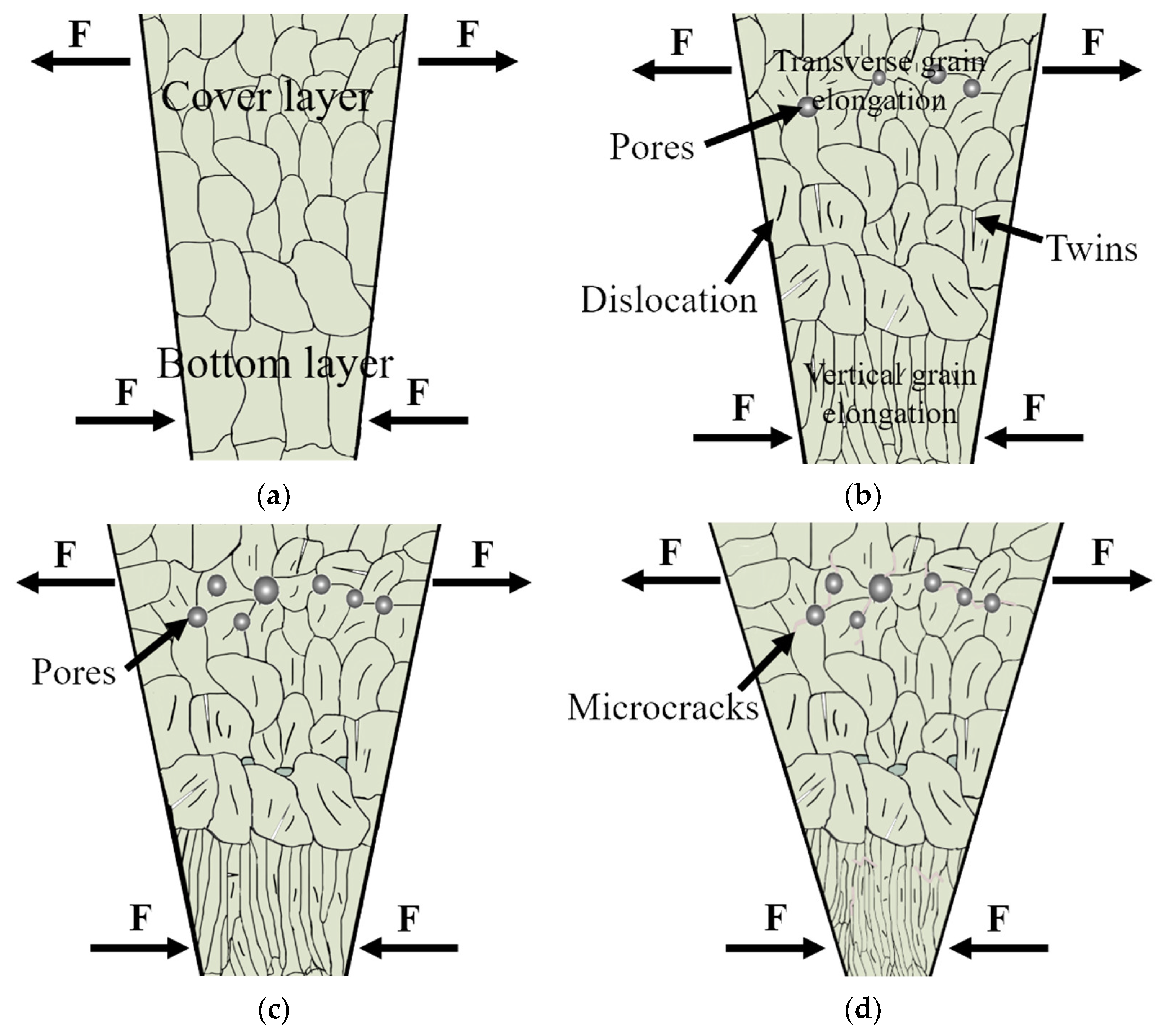
3.3. Face Bend Property
4. Conclusions
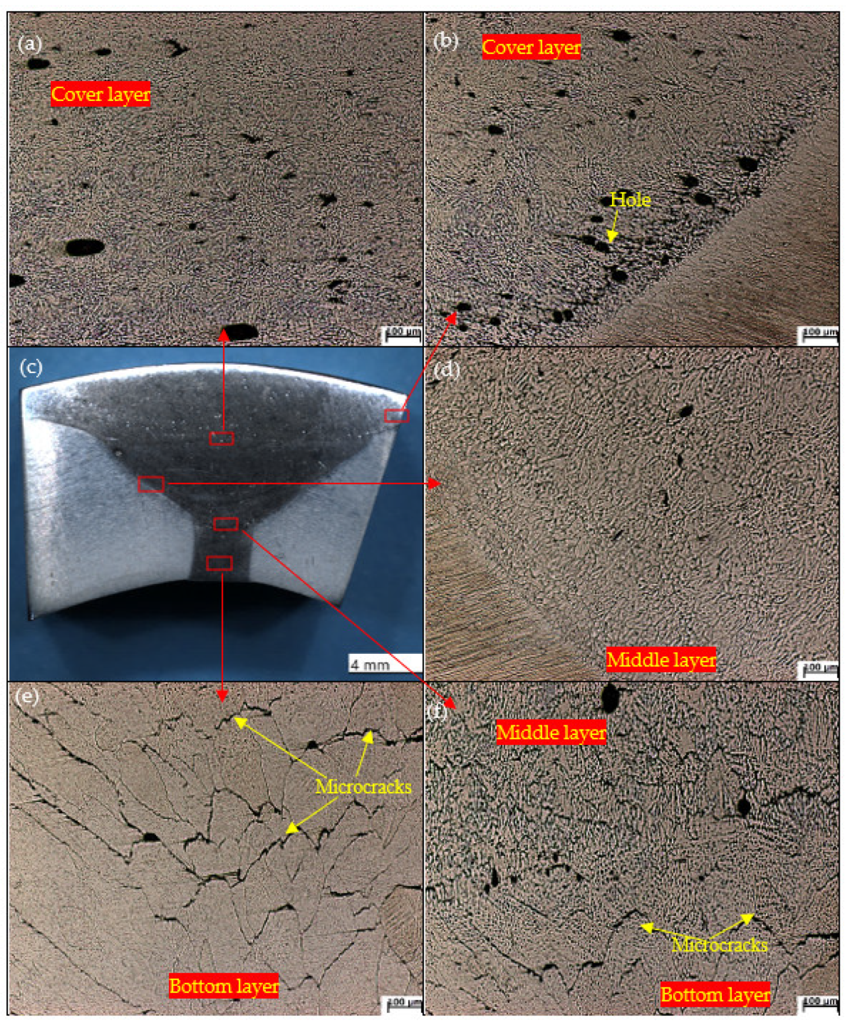
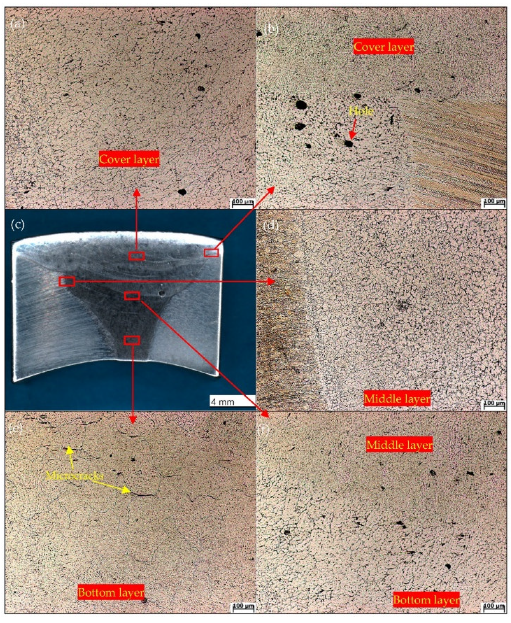
- (1)
- For the two kinds of welded joints, the grain of the weld structure became coarser from the cover layer to the bottom layer since the number of heating cycles increased gradually. The WZ of the ER5087 welded joint had a smaller grain size than the ER5356 welded joint.
- (2)
- The minimum microhardness values of ER5356 and ER5087 welded joints were in the WZ, 70.37 hv and 72.9 hv, respectively. The microhardness of the ER5087 welded joint was slightly higher than that of the ER5356 welded joint.
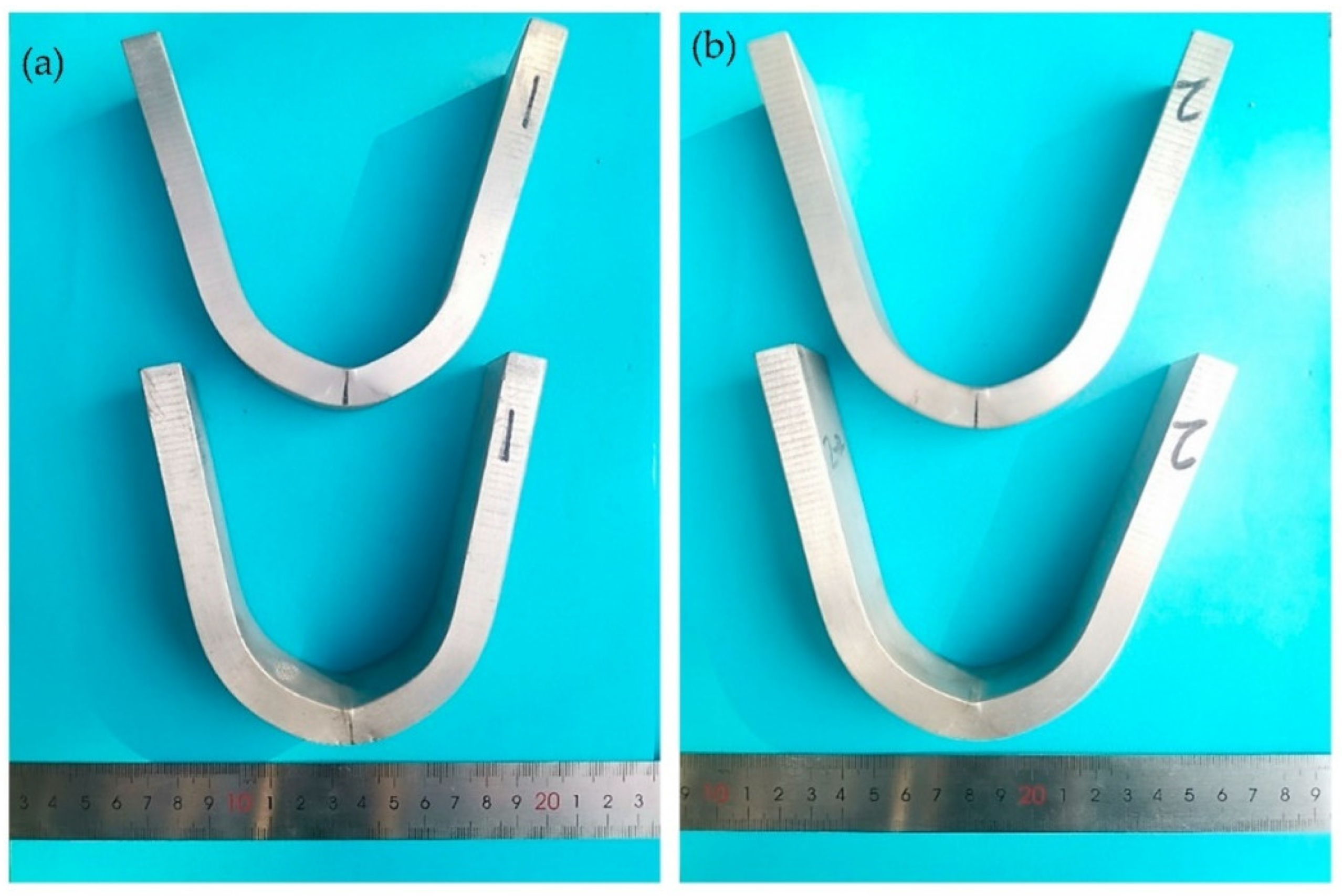
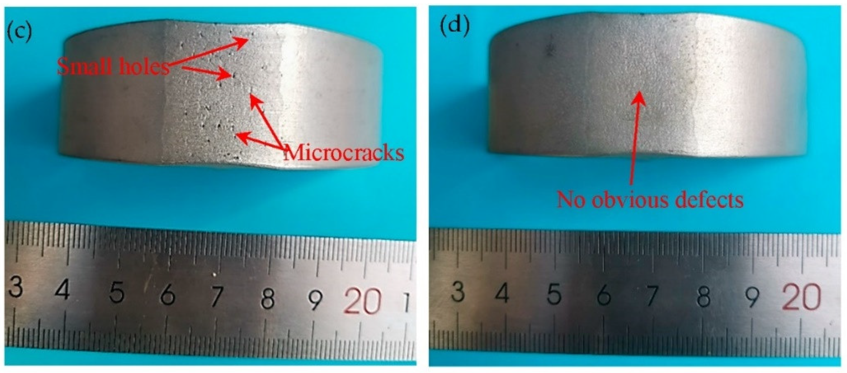
- (3)
- Two kinds of welded joints were not broken via the face-bend test. However, there were some small holes and microcracks on the surface of the ER5356 welded joint, and there were no obvious defects on the surface of the ER5087 welded joint. The ER5087 welded joint had a better bending performance than the ER5356 welded joint.
Author Contributions
Funding
Institutional Review Board Statement
Informed Consent Statement
Data Availability Statement
Conflicts of Interest
References
- Liu, W.Y.; Wu, D.T.; Duan, S.W.; Wang, T.; Zou, Y. A study on fatigue crack propagation for friction stir welded plate of 7N01 Al-Zn-Mg alloy by EBSD. Materials 2020, 13, 330. [Google Scholar] [CrossRef] [PubMed] [Green Version]
- Li, B.; Wang, X.M.; Chen, H.; Hu, J.; Huang, C.; Gou, G.Q. Influence of heat treatment on the strength and fracture toughness of 7N01 aluminum alloy. J. Alloys Compd. 2016, 678, 160–166. [Google Scholar] [CrossRef]
- Xie, H.; Xiao, Z.; Li, Z.; Wang, M.; Ma, S.; Jiang, H. Quench sensitivity of AA7N01 alloy used for high speed train body structure. JOM 2019, 71, 1681–1686. [Google Scholar] [CrossRef]
- Wu, L.; Yang, B.; Han, X.; Ma, G.L.; Xu, B.X.; Liu, Y.H.; Song, X.G.; Tan, C.W. The microstructure and mechanical properties of 5083, 6005A and 7N01 aluminum alloy gas metal arc-welded joints for high-speed train: A Comparative Study. Metals 2022, 12, 213. [Google Scholar] [CrossRef]
- Shen, L.; Chen, H.; Che, X.L.; Xu, L.D. Corrosion–fatigue crack propagation of aluminum alloys for high-speed trains. Int. J. Mod. Phys. B 2017, 31, 1744009. [Google Scholar] [CrossRef]
- Liu, D.S.; Wei, P.; Long, W.M.; Zhou, W.; Wang, J.Y. Effect of welding wires on fatigue property of 7N01-T4 aluminium alloy joints. Sci. Technol. Weld. Join. 2020, 26, 1–10. [Google Scholar] [CrossRef]
- Xie, H.; Hu, L.; Ma, Q.H.; Meng, W.; Yin, X.H. Microstructure and mechanical properties of A7N01 aluminum alloy weld joints filled with ER5356 and ER5087 weld wires. J. Min. Metall. Sect. B 2022, 58, 157–167. [Google Scholar] [CrossRef]
- Ishak, M.; Salleh, M.N.M.; Aisha, S.R. The mechanical and microstructural study of welded AA7075 using different filler metals. Int. J. Comp. Meth-Sing. 2017, 5, 696–712. [Google Scholar] [CrossRef]
- Peng, X.Y.; Cao, X.W.; Xu, G.F.; Deng, Y.; Tang, L.; Yin, Z.M. Mechanical properties, corrosionbehavior, and microstructures of a MIG-welded 7020 Al alloy. J. Mater. Eng. Perform. 2016, 25, 1028–1040. [Google Scholar] [CrossRef]
- Huan, P.C.; Wang, X.N.; Zhang, J. Effect of wire composition on microstructure and properties of 6063 aluminium alloy hybrid synchronous pulse CMT welded joints. Mater. Sci. Eng. A 2020, 790, 139713. [Google Scholar] [CrossRef]
- Huang, J.W.; Yin, Z.M.; Lei, X.F. Microstructure and properties of 7A52 Al alloy welded joint. Trans. Nonferr. Met. Soc. China 2008, 18, 804–808. [Google Scholar] [CrossRef]
- Zhao, Z.H.; Xu, Z.; Wang, G.S. Effect of Sc, Zr, Er in ER5356 welding wire on mechanical properties of welded joint of 7A52 Aluminum Alloy. J. Mater. Res. 2013, 27, 287–291. (In Chinese) [Google Scholar]
- Yang, D.X.; Li, X.Y.; He, D.Y.; Huang, H. Effect of minor Er and Zr on microstructure and mechanical properties of Al–Mg–Mn alloy (5083) welded joints. Mater. Sci. Eng. A 2013, 561, 226–231. [Google Scholar] [CrossRef]
- Deng, Y.; Peng, B.; Xu, G.; Pan, Q.; Ye, R.; Wang, Y.; Lu, L.; Yin, Z. Stress corrosion cracking of a high-strength friction-stir-welded joint of an Al-Zn-Mg-Zr alloy containing 0.25 wt% Sc. Corros. Sci. 2015, 100, 57–72. [Google Scholar] [CrossRef]
- Fu, L.; Peng, Y.Y.; Huang, J.W.; Deng, Y.; Yin, Z.M. Microstructures and mechanical properties of Gas Tungsten Arc Welded joints of new Al–Mg–Sc and Al–Mg–Er alloy plates. Mater. Sci. Eng. A 2015, 620, 149–154. [Google Scholar] [CrossRef]
- Lei, X.F.; Deng, Y.; Peng, Y.Y. Microstructure and Properties of TIG/FSW Welded Joints of a New Al-Zn-Mg-Sc-Zr Alloy. J. Mater. Eng. Perform. 2013, 22, 2723–2729. [Google Scholar] [CrossRef]
- Dutra, J.C.; Savi, B.M.; Marques, C.; Régis, H.; Alarcon, O.E. Metallurgical characterization of the 5083H116 aluminum alloy welded with the cold metal transfer process and two different wire-electrodes (5183 and 5087). Weld. World 2015, 59, 797–807. [Google Scholar] [CrossRef]
- Xu, W.F.; Liu, J.H.; Luan, G.H.; Dong, C.L. Microstructure and mechanical properties of friction stir welded joints in 2219-T6 aluminum alloy. Mater. Des. 2009, 30, 3460–3467. [Google Scholar] [CrossRef]
- Kimura, M.; Suzuki, K.; Kusaka, M.; Kaizu, K. Effect of friction welding condition on joining phenomena, tensile strength, an-d bend ductility of friction welded joint between pure aluminium and AISI 304 stainless steel. J. Manuf. Process. 2017, 25, 116–125. [Google Scholar] [CrossRef]
- Lin, H.Q.; Ye, L.Y.; Sun, L.; Xiao, T.; Liu, S.D.; Deng, Y.L.; Zhang, X.M. Effect of three-step homogenization on microstructure and properties of 7N01 aluminum alloys. Trans. Nonferr. Met. Soc. China 2018, 28, 829–838. [Google Scholar] [CrossRef]
- Deng, Y.; Peng, B.; Xu, G.F.; Pan, Q.L.; Yin, Z.M.; Ye, R.; Wang, Y.J.; Lu, L.Y. Effects of Sc and Zr on mechanical property and microstructure of tungsten inert gas and friction stir welded aerospace high strength Al–Zn–Mg alloys. Mater. Sci. Eng. A 2015, 639, 500–513. [Google Scholar] [CrossRef]
- Rokhlin, L.L.; Dobatkina, T.V.; Bochvar, N.R.; Lysova, E.V. Investigation of phase equilibria in alloys of the Al–Zn–Mg–Cu–Zr- Sc system. J. Alloys Compd. 2004, 367, 10–16. [Google Scholar] [CrossRef]
- Kattner, U.R.; Boerringer, W.J. Thermodynamic calculation of the ternary Ti-Al-Nb system. Mater. Sci. Eng. A 1992, 152, 9–17. [Google Scholar] [CrossRef]
- Chen, Z.; Yan, K. Grain refinement of commercially pure aluminum with addition of Ti and Zr elements based on crystallography orientation. Sci. Rep. 2020, 10, 16591. [Google Scholar] [CrossRef] [PubMed]
- Gu, J.; Yang, S.; Xiong, Q.; Duan, C. Microstructure and mechanical study on laser-arc-welded Al–Zn–Mg alloy. Mater. Trans. 2020, 61, 119–126. [Google Scholar] [CrossRef]
- Mcclelland, Z.; Li, B.; Horstemeyer, S.J.; Brauer, S.; Adedoyin, A.A.; Hector, L.G., Jr.; Horstemeyer, M.F. Geometrically necessary twins in bending of a magnesium alloy. Mater. Sci. Eng. A 2015, 645, 298–305. [Google Scholar] [CrossRef]
- Peng, J.F.; Liu, J.H.; Cai, Z.B.; Shen, M.X.; Song, C.; Zhu, M.H. Study on bending fretting fatigue damages of 7075 aluminum alloy. Tribol. Int. 2013, 59, 38–46. [Google Scholar] [CrossRef]
- Furykawa, M.; Horita, Z.; Nemoto, M.; Valiev, R.Z.; Langdon, T.G. Microhardness measurements and the Hall-Petch relationship in an Al-Mg alloy with submicrometer grain size. Acta Mater. 1996, 44, 4619–4629. [Google Scholar] [CrossRef]


| Alloy | Si | Fe | Cu | Mn | Mg | Zn | Ti | Cr | Zr | Al |
|---|---|---|---|---|---|---|---|---|---|---|
| 7N01-T4 | ≤0.30 | ≤0.30 | ≤0.20 | 0.2–0.7 | 1.0–2.0 | 4.0–5.0 | ≤0.20 | ≤0.30 | — | Bal. |
| ER5356 | 0.05 | 0.10 | <0.01 | 0.14 | 5.00 | <0.01 | 0.07 | 0.06 | — | Bal. |
| ER5087 | 0.25 | 0.40 | 0.05 | 0.90 | 4.80 | 0.25 | 0.15 | 0.15 | 0.15 | Bal. |
| Weld Layer | Welding Current/A | Welding Voltage V | Welding Speed/(mm∙s−1) |
|---|---|---|---|
| The cover layer | 250 | 24 | 8 |
| The middle layer | 260 | 24.5 | 7 |
| The bottom layer | 250 | 24 | 7 |
Publisher’s Note: MDPI stays neutral with regard to jurisdictional claims in published maps and institutional affiliations. |
© 2022 by the authors. Licensee MDPI, Basel, Switzerland. This article is an open access article distributed under the terms and conditions of the Creative Commons Attribution (CC BY) license (https://creativecommons.org/licenses/by/4.0/).
Share and Cite
Wei, P.; Wu, M.; Liu, D.; Liang, Y.; Zhao, Z. Face Bend Property of 7N01-T4 Aluminum Alloy MIG Welded Joint by Using Different Welding Wires. Metals 2022, 12, 873. https://doi.org/10.3390/met12050873
Wei P, Wu M, Liu D, Liang Y, Zhao Z. Face Bend Property of 7N01-T4 Aluminum Alloy MIG Welded Joint by Using Different Welding Wires. Metals. 2022; 12(5):873. https://doi.org/10.3390/met12050873
Chicago/Turabian StyleWei, Ping, Mingfang Wu, Dashuang Liu, Yun Liang, and Ziqiang Zhao. 2022. "Face Bend Property of 7N01-T4 Aluminum Alloy MIG Welded Joint by Using Different Welding Wires" Metals 12, no. 5: 873. https://doi.org/10.3390/met12050873