Article

Dynamic Interaction between Dislocation and Irradiation-Induced Defects in Stainless Steels during Tensile Deformation

1
Research Institute of Nuclear Engineering, University of Fukui, Fukui 914-0055, Japan
2
Institute of Advanced Energy, Kyoto University, Kyoto 611-0011, Japan
*
Author to whom correspondence should be addressed.
Metals 2022, 12(5), 762; https://doi.org/10.3390/met12050762
Submission received: 5 March 2022 / Revised: 24 April 2022 / Accepted: 28 April 2022 / Published: 29 April 2022
(This article belongs to the Special Issue Study of Microstructure and Irradiation Damages in Metals and Alloys)

Abstract

:
A series of in-situ transmission electron microscopy (TEM) observations during tensile deformation were conducted on the ion-irradiated stainless steel. The jerky motion of dislocations appeared, and dislocations were pinned and depinned at the defects through the in-situ TEM observation. The jump distance traveled by dislocation was measured and discussed as the mean interval of defects interacting with the dislocation motion. Microstructural information of irradiation defects such as obstacle interval was obtained by TEM and atom probe tomography (APT), and the type of pinning site was identified. It was found that Frank loops and black dots were irradiation defects that strongly interacted with dislocations. It was suggested that solute atom clusters act as weak obstacles for dislocations in the dynamic interaction behavior with dislocation motion.

1. Introduction

Austenitic stainless steels, which are used as structural materials in nuclear reactors, are hardened by neutron irradiation in the nuclear reactors. Irradiation of approximately 1 dpa significantly accelerates irradiation hardening and greatly reduces their ductility [1]. In this process, the irradiation defects formed by neutron irradiation make dislocation motion pinned and inhibit their motion through the process of dislocation bowing out. Unpinning dislocation forms a dislocation channel with sweeping out the defects and leads to a large loss of ductility, which is known to be the cause of irradiation-assisted stress corrosion cracking; this poses an issue from the perspective of structural integrity maintenance in high-aged nuclear power reactors [2]. Three types of irradiation defects, Frank loops (FLs), black dots (BDs), and solute clusters (SCs), were identified as the primary defects in stainless steels under the operating conditions of light-water reactors [3]. Understanding the contribution of each irradiation defect to irradiation hardening is essential for evaluating the amount of irradiation hardening increase. In considering the hardening contribution of each defect, ion irradiation is a useful tool for introducing the defect in the materials compared with neutron irradiation, even though knowledge about the correlation of microstructure and mechanical properties between neutron irradiation and ion irradiation is not enough to obtain a comprehensive understanding.
The analyses of mechanical property changes and behavior before and after ion irradiation have been performed as local probes using specific techniques such as continuous stiffness measurement by nano-indentation [4], pillar compression method, pillar splitting method, micro-cantilever method [5], and in situ TEM tensile test [6]. These new technologies provided us a grasp of the correlation between mechanical behavior and microstructural changes during local deformation in failure and represented the usefulness in the evaluation of mechanical properties in the range from micro- to macro-scale. Further, the in-situ TEM observation during tensile deformation can provide microscopic information that cannot be obtained using conventional TEM work by direct observation of the dislocation interaction with defect clusters [7,8]. Nogiwa reported that in-situ TEM observations of dislocation gliding through copper precipitates in thermally aged or irradiated Fe-Cu alloys under stress, and it succeeded in discovering the obstacles strength on copper precipitate, which was invisible in the conventional TEM observations [9]. However, this technique is not widely used for invisible cluster evaluation because of the high level of skills and experience required for the observation and sample preparation.
In this study, the in-situ TEM observations during tensile deformation were conducted on the Fe ion-irradiated stainless steels. Mobile dislocations were treated as probes for investigating the dislocation interaction with irradiation-induced defect clusters during the observations, and the obstacle interval was estimated by focusing on their interaction with the irradiated defects as pinning/depinning behavior of mobile dislocations.

2. Materials and Methods

2.1. Sample Materials and Pre-Irradiation Preparation

Austenitic stainless steel (SUS316L steel: Fe bal., Cr 18 wt%, Ni 14 wt%, Mo 2.5 wt%, Mn 1.5 wt%, Si 0.4 wt%, C 0.016 wt%, P 0.02 wt%, S 0.002 wt%) was used as the sample material. Specimens were punched out as a piece with dimensions of 11.5 mm × 2.2 mm × 0.2 mm (length, width, and thickness, respectively), with holes on both ends for fastening in the tensile strength test. Solid solution heat treatment was performed for 2 h at 1100 °C in a vacuum atmosphere and air cooling to remove molding distortions and coarsen crystal grains. The sample surface was electrolytically polished to make it smooth using a jet electrolytic-polishing device, TenuPol5 (Struers, Copenhagen, Denmark).

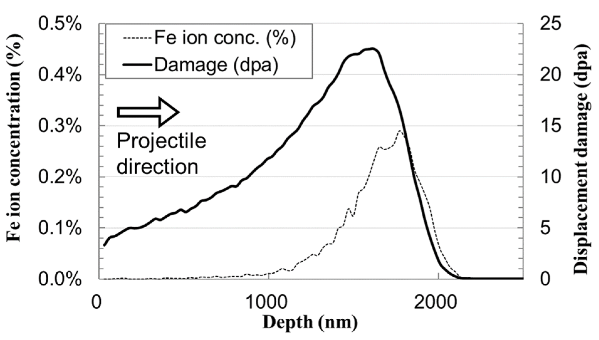
2.2. Ion Irradiation

Iron ion irradiation was performed using the tandem accelerator at the Dual-Beam Facility for Energy Science and Technology (DuET), Institute of Advanced Energy, Kyoto University (Kyoto, Japan) [10]. A damage distribution was formed in the depth direction during ion irradiation, and the maximum damage amount and damage peak depth were calculated using the Monte Carlo simulation code, SRIM2008.1 [11]. Figure 1 shows an example of the damage distribution by ion irradiation and the ion implementation distribution in a Fe-14Cr-16Ni alloy. The self-ion Fe3+ was used, which reduces the chemical effect of projectile ion in ion implantation on stainless steel because the maximum amount of Fe ion implantation in the matrix was less than 0.5%. Table 1 lists the irradiation conditions employed.

2.3. Post-Irradiation Preparation

The Fe ion-irradiated 316 L steel sample was thinned to a level that allows TEM observations while keeping limited areas with irradiation defects. Two types of electropolishing were employed. The first step was section polishing, in which the irradiated surface was polished to the layer directly above the irradiation damage peak. An electrolytic bath system was used for section polishing, and removal from a depth of 1.5 µm to the surface was performed using an electrolytic-polishing solution of methanol and sulfuric acid (1:5) at a temperature of 3 °C; the polishing current was adjusted at 1 A currency. A wrapped area of nail enamel was introduced at the edge of the irradiated surface, and the level difference at the boundary of the wrapped area and polished surfaces was measured using scanning electron microscopy (SEM) to determine the amount of the depth removed from the surface. The time required to remove a depth of 1.5 μm was 0.6 s. Next, electropolishing was performed on the opposite side of the irradiated surface of the sample, and a hole was burrowed at the center of the sample to prepare it such that the irradiated area would remain only at the thin-film portion that surrounds the hole. Tensile tests in a column in TEM were performed on the thin-film region containing irradiation defects.

2.4. In-Situ TEM Observation Experiments during Tensile Deformation

The in-situ TEM observation during tensile deformation was conducted using the JEM-1300NEF high-voltage electron microscope and GATAN672 short-axis tilting heated tensile holder at the Ultramicroscopy Research Center, Kyushu University (Fukuoka, Japan) [12]. The acceleration voltage of 1250 kV was quite high, offering several advantages such as the capability to observe thick materials and enhanced image quality due to the reduction in background intensity. The examination was conducted at 50 °C lower than the irradiation temperature. The sample was pulled in the longitudinal direction to generate a dislocation motion by causing plastic deformation around the hole, and the time-sequential change of microstructure during tensile deformation was observed and recorded on a PC with a frame rate of 10 fps. The tensile holder was a single-axis holder, and the crystallographic configuration of the obtained image was limited. To remove the electron irradiation damage, the electron beam was expanded to observe the microstructure. During the observation, it was performed while confirming that no damage evolution was caused by electron irradiation. In the case of the unirradiated sample, the dislocations were moving smoothly without any trapping and pinning motion in the matrix through the in-situ TEM observation during the tensile test.
To obtain information on the FLs and BDs, which are irradiation defects that can be observed using a conventional TEM, the samples were cut out from the tensile specimen after the tensile test, and its TEM observation was performed using a double-axial tilting holder, EM-31630 in the conventional TEM (JEM-2100TM, University of Fukui, Fukui, Japan).
In order to extract an APT sample, damage distribution in the ion-irradiated specimen was confirmed by a cross-sectional TEM observation. Figure 2 shows a cross-sectional depth observation photograph of sample 2 extracted and formed using an FIB. A region of accumulated irradiation defects was observed at a depth of 2.3 μm from the surface. An APT specimen was extracted at a depth of 1500–1700 nm by the FIB sampling method.
To obtain information on SCs, APT observations using the LEAP3000XHR (Imago Inc., Madison, WI, USA) were performed on irradiation sample 1. An APT observation was carried out at the RI facility in the “Fugen” site in JAEA Tsuruga [13]. The microstructural data obtained from previous work were used for irradiation sample 2 [14].

3. Results

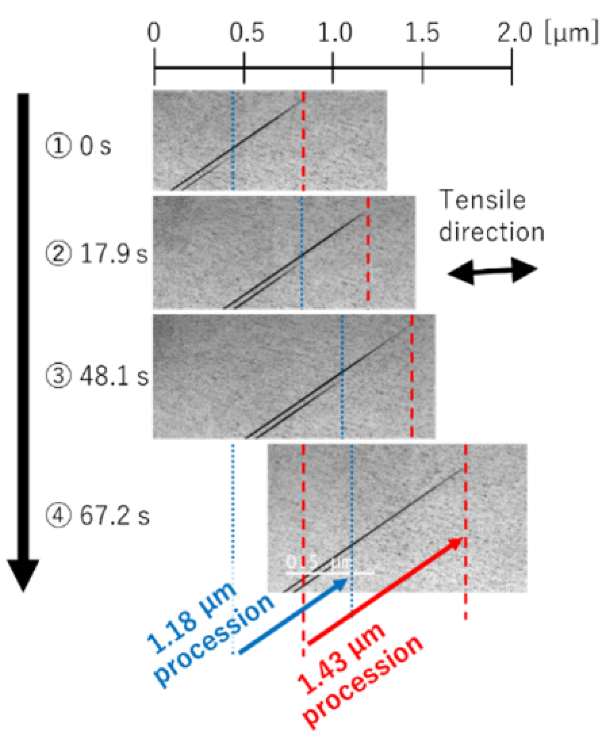
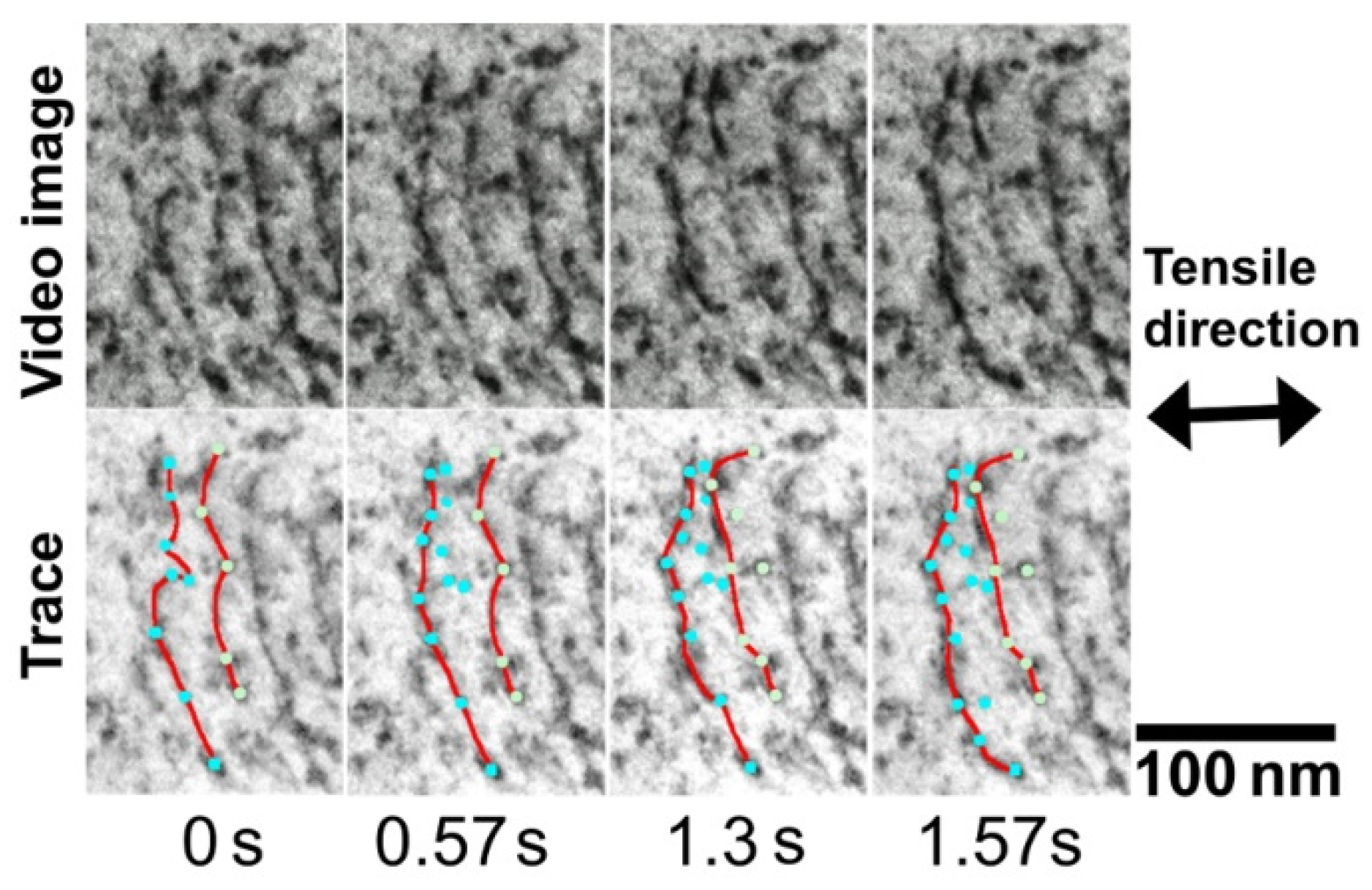
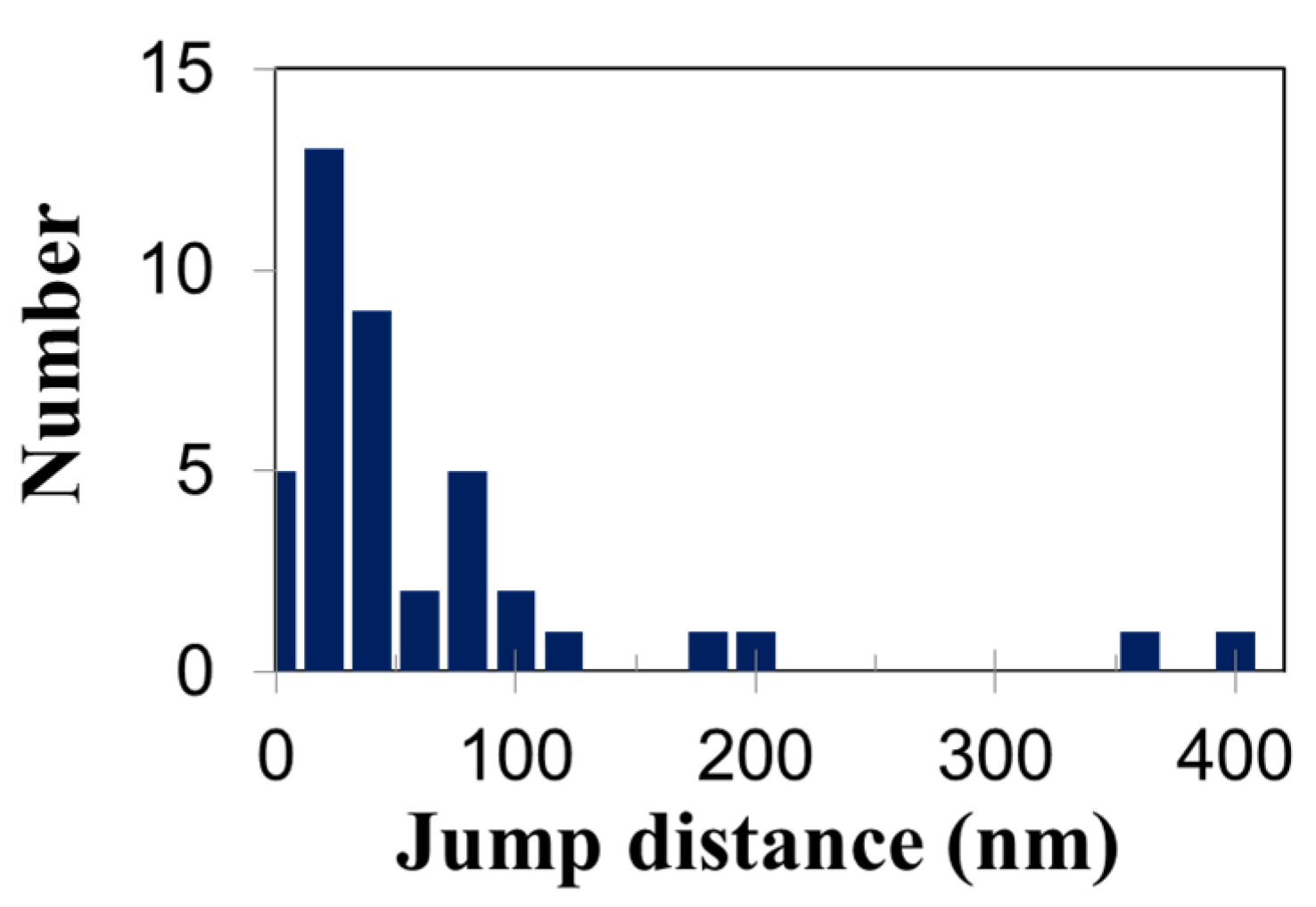
3.1. Results of the Tensile In-Situ TEM Observation

The motion of edge-on extended dislocation/fault showing a dislocation line on the surface, which was parallel to the electron beam direction in the sample, was observed in the irradiated sample 1 (see Figure 3). In the irradiated sample 2, the dislocation line exhibited a sliding motion on a slip plane that was not parallel to the electron beam direction (see Figure 4). Both the dislocation motion was observed dynamically and moved on {111} type of slip plane. The diffraction pattern was also recorded to investigate the electron injection direction in the video. The slip plane and dislocation line direction were determined through the electron diffraction analysis.
Figure 3 shows a TEM image acquired from the observation footage of the edge-on extended dislocation formation. The direction of the extension of the two extended dislocations was [ 0 1 ¯ 1 ] . From the footage, the dislocations were found to have a jerky motion in the formation. The reason for the interruptions in the dislocation motion was that the irradiation defect acted as an obstacle against the dislocation motion. The distance traveled by the dislocation was measured, and the data were processed based on the image correction of the sliding direction and observation results of the dislocation motion at different positions. As a result, the jump distance traveled by dislocation was determined to be approximately 50 nm.
The observation image of the dislocation motion in sample 1 indicated linear motion, as shown in Figure 3. Another image of dislocation motion in sample 2 indicated dislocation line pinning on irradiation defects along with motion with gradual overhanging. Figure 4 shows the time-sequential images of dislocation motion, which is pinning /depinning at the defects. The upper part of video images are the corrected images of dislocation motion in which the image is normal to the slop plane. In the bottom part, the red line indicates the two dislocations, and the blue and green dots indicate pinning points where dislocations stopped interacting with defects. The mean interval of the first dislocation among the pinning points was set as the obstacle interval, which was approximately 31 nm.

3.2. Post-Tensile TEM Observation Results

The number and mean diameters of the defects were measured for FL images formed using the relrod method [15], which enables FL defect-specific observation, and BD images formed using the bright field (BF) and weak-beam dark-field (WBDF) methods, which enable BD defect-specific observation. Meanwhile, the sample thickness in the observation range was determined using equal-thickness fringes or K-M fringes. From the above data, the volume number densities of the FL and BD defects were measured, and the results are presented in Table 2.

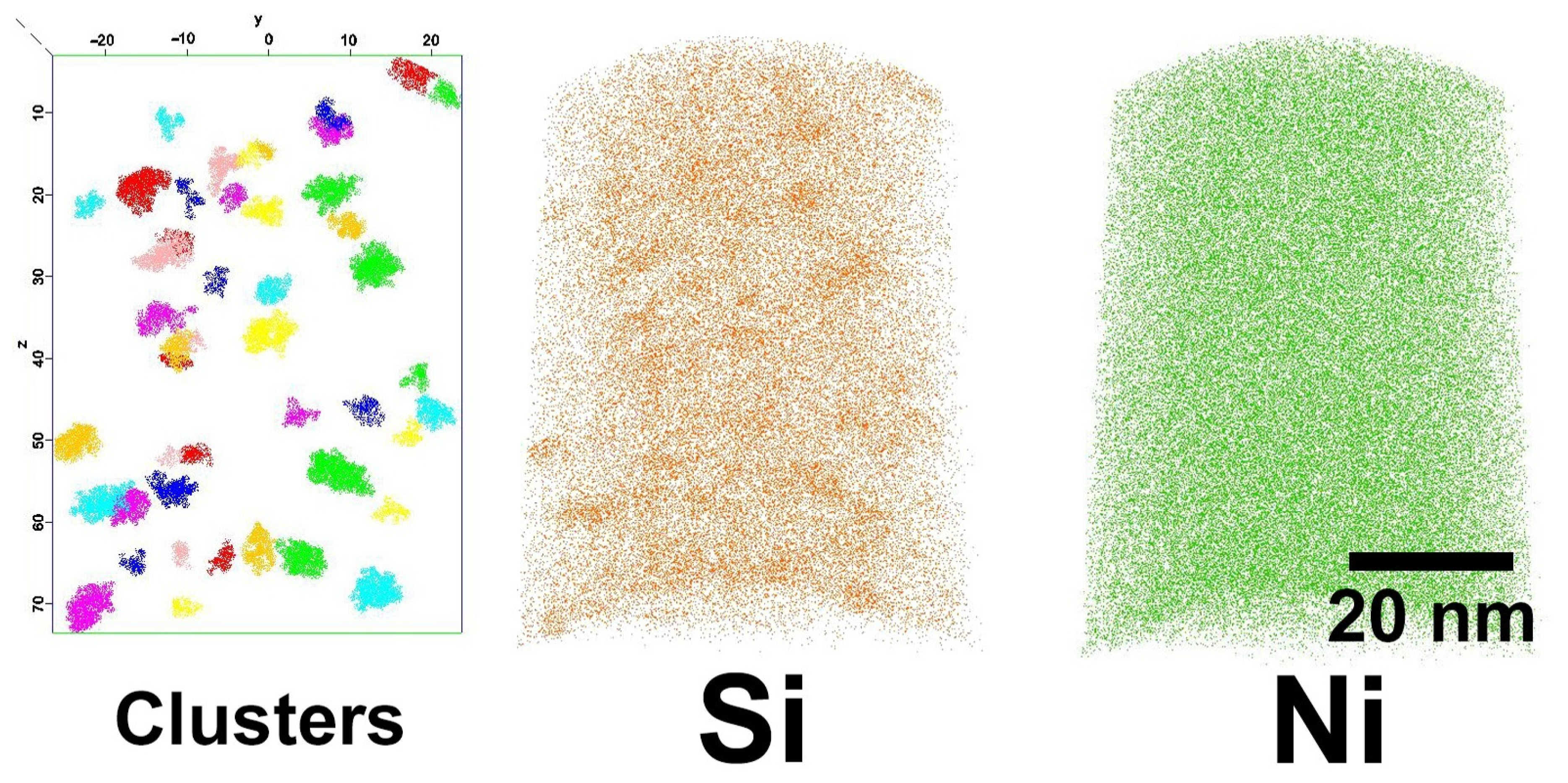
3.3. The Solute Atomic Cluster from APT
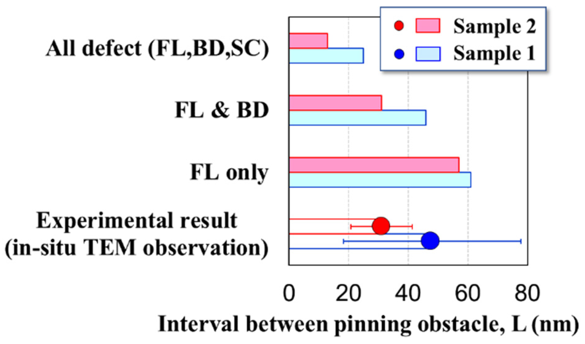
The atomic mass of the APT observation performed on irradiated sample 1 indicated that the solute atoms of Si were clustered. Figure 5 shows colored maps of the clusters, focusing on Si and Ni. Table 3 lists the calculated volume number densities and mean diameters. The APT observation could not be performed on irradiation sample 2; therefore, data from literature reporting results of similar conditions [14] were used for sample 2. Table 3 presents the results accordingly.

4. Discussion

Figure 6 shows a histogram of the mean obstacle interval obtained from the mean jump distance by the pinning/depinning of dislocations observed in irradiation sample 1. Cases with wide dislocation jump distances indicated large jumps during tensile application and hence were considered jumps that occurred during large stress loading. In addition, jumps of 100 nm or less were adopted as the obstacle interval distance by pinning/depinning to determine the obstacle interval of the irradiation defects confirmed during dynamic observation.
The distributed-barrier hardening (DBH) model has conventionally been used to show the correlation between the irradiation microstructure and hardness, and the following equation holds in the DBH model between the volume number density Nv and diameter d of defects and increased applied stress ∆σ [16,17].
σ c = M α μ b N v d
where M is the Taylor factor, α is the obstacle strength, μ is the shear modulus, and b is the magnitude of the Burgers vector. The square sum of the deformation stress increments for each irradiated defect yielded Δσ. The obstacle strength is generally determined by the type of defect, and previous studies reported that α = 0.4 for FLs, α = 0.2 for fine BDs, and α = 0.02 to 0.11 for solute atom clusters [14,18,19,20]. From the literature survey, the ease of pinning of dislocations caused by defects is in the order FL > BD >> SC. Since three defect clusters were observed in this work and some defects interacted with mobile dislocation, we verified which defects interacted with the dislocations. The three possible pinning combinations that can be observed via dynamic observation are: (1) FLs only, (2) FLs and BDs, and (3) all defects as FLs, BDs, and SCs.
In addition, irradiation defects that act as obstacles are randomly distributed in three dimensions [21]. In this case, obstacle interval L0 was approximated by the following equation [9]:
L 0 = 1 / d N v
where Nv represents the obstacle volume density and d is the diameter. For the obstacle interval with a mix of multiple defects, the number density was used for each sum, and the mean diameter was used with the weighted average considering the number density.
The obstacle interval obtained from the dynamic observation of edge-in dislocation channel formation and the obstacle interval calculated by Equation (2) using the results of post-tensile TEM and APT observations were compared for irradiation sample 1 as shown in Figure 7. The results indicate that the combination of FLs and BDs exhibits the closest obstacle interval, suggesting that the irradiation defects confirmed by dynamic observation of the edge-on dislocation channel formation are FLs and BDs.
Next, the jump distance obtained from the dynamic observation of dislocation motions in irradiation sample 2, obtained from Equation (2), and obtained from previous literature were compared in Figure 7. Comparing the jump distance obtained by the in-situ observation and obstacle interval for a combination of various defects, the obstacle interval of a combination of FL and BD showed a suitable coincidence with the jump distance. From the experimental results, it is suggested that FLs and BDs function as obstacles, and it is unlikely that the SC act as a pinning site against dislocations motion; thus, the strength of SCs as obstacles was quite low.
Applying the DBH model as an SC hardening model, assuming distributed reinforcement with strength equivalent to FL or BD, would be inappropriate. Therefore, an appropriate DBH model for SCs in cases where both strong and weak obstacles coexist should be applied for FLs and BDs as strong obstacles and SCs as weak obstacles, which can be hardened owing to their high number density [16,17]. From the results of this work, a model with coexisting strong and weak obstacles is recommended as the irradiation hardening model of irradiated stainless steels. Even though the order of obstacle strength, α, was reported as FL > BD >> SC as mentioned from the statistically microstructural analysis, it is evident that this correlation between the type of defects and hardening contribution was verified and confirmed by the dynamic behavior of dislocation interaction, using the probes for dislocation interaction with defects in the in-situ TEM observation during the tensile test.
Conclusively, dynamic TEM observation for dislocation interaction with defects indicated directly that BDs and FLs function as pinning and trapping sites as mobile dislocations and contribute to irradiation hardening. The solute atomic clusters were not found to function as pinning sites through the dynamic TEM observation experiment but were considered to contribute to irradiation hardening by their dense distribution of fine defects.

5. Conclusions

A series of in-situ TEM observations during tensile deformation was conducted on the Fe ion-irradiated stainless steels. Mobile dislocations were treated as probes for investigating the dislocation interaction with irradiation-induced defect clusters during the observations, and the jump distance was estimated by focusing on their interaction with the irradiated defects as pinning/depinning behavior of mobile dislocations.
A structural material in nuclear reactors, SUS316L steel was irradiated with self-ion irradiation to induce irradiation defects in the material, and the in-situ TEM observation during tensile deformation was employed as an experimental approach to investigate the dislocation interaction with irradiation-induced defect clusters.
The number density and mean diameter of black dot, Frank loop, and solute atom cluster were measured by APT and conventional TEM observations, and the obstacle interval of each defect was obtained. The jump distance traveled by dislocations in the in-situ TEM observations was measured from video analysis of a series of time-sequential images for dislocation motion pinned/depinned during tensile tests.
Comparing the jump distance obtained by the in-situ observation and obstacle interval for a combination of various defects, the obstacle interval of a combination of FL and BD showed a suitable coincidence with the jump distance. It is suggested that FLs and BDs function as obstacles, and it is unlikely that the SC act as a pinning site against dislocations motion; thus, the strength of SCs as obstacles was quite low. The solute atomic clusters were not found to function as pinning sites through the dynamic TEM observation experiment but were considered to contribute to irradiation hardening by their dense distribution of fine defects.

Author Contributions

Conceptualization, K.-i.F.; TEM observation, K.-i.F.; Sample preparation, K.U.; Ion irradiation, K.Y. and K.U.; Manuscript writing, K.-i.F. All authors have read and agreed to the published version of the manuscript.

Funding

This work was supported by JSPS KAKENHI (Grant Numbers JP19K05326 and JP19H02643). This work was partly supported by the Advanced Characterization Platform of the Nanotechnology Platform Japan (JPMXP09A21KU0412), sponsored by the Ministry of Education, Culture, Sports, Science and Technology (MEXT), Japan.

Institutional Review Board Statement

Not applicable.

Informed Consent Statement

Not applicable.

Data Availability Statement

Not applicable.

Acknowledgments

We are grateful to H. Maeno of Kyushu University for his helpful support in transmission electron microscopy analysis.

Conflicts of Interest

The authors declare no conflict of interest.

References

  1. Fukuya, K. Current understanding of radiation-induced degradation in light water reactor structural materials. J. Nucl. Sci. Technol. 2013, 50, 213–254. [Google Scholar] [CrossRef] [Green Version]
  2. Was, G.S.; Andresen, P.L. Stress Corrosion Cracking Behavior of Alloys in Aggressive Nuclear reactor Core Environments. Corrosion 2007, 63, 19–45. [Google Scholar] [CrossRef]
  3. Fukuya, K.; Nishioka, H.; Fujii, K. Irradiation Behavior of Stainless Steel in LWR, INSS Monograph.4; INSS: Mihama, Japan, 2009; pp. 22–36, 55–64. (In Japanese) [Google Scholar]
  4. Kasada, R.; Takayama, Y.; Yabuughi, K.; Kimura, A. A new approach to evaluate irradiation hardening of ion-irradiated ferritic alloys by nano-indentation techniques. Fusion Eng. Des. 2011, 86, 2658–2661. [Google Scholar] [CrossRef] [Green Version]
  5. Ast, J.; Gheidelli, M.; Furst, K.; Goken, M.; Sebastiani, M.; Korsunsky, A.M. A review of experimental approaches to fracture toughness evaluation at the micro-scale. Mater. Des. 2019, 173, 107762. [Google Scholar] [CrossRef]
  6. Ghidelli, M.; Orekhov, A.; Li Bassi, A.; Terraneo, G.; Djemia, P.; Abadias, G.; Nord, M.; Beche, A.; Gauquelin, N.; Verbeeck, J.; et al. Novel class of nanostructured metallic glass films with superior and tunable mechanical properties. Acta Mater. 2021, 213, 116955. [Google Scholar] [CrossRef]
  7. Tougou, K.; Onitsuka, T.; Fukumoto, K.-I.; Uno, M.; Muta, H. The study of hardening evaluation of pure Zr with δ-hydrides generation by the dynamic in-situ metallic structure observation and nano-indentation hardness test. J. Nucl. Mater. 2018, 511, 284–296. [Google Scholar] [CrossRef]
  8. Tougou, K.; Shikata, A.; Kawase, U.; Onitsuka, T.; Fukumoto, K. In-situ TEM observation of dynamic interaction between dislocation and cavity in BCC metals in tensile deformation. J. Nucl. Mater. 2015, 465, 843–848. [Google Scholar] [CrossRef]
  9. Nogiwa, K.; Yamamoto, T.; Fukumoto, K.; Matsui, H.; Nagai, Y.; Yubuta, K.; Hasegawa, M. In-Situ TEM observation of dislocation movement through the ultrafine obstacles in an Fe alloy. J. Nucl. Mater. 2002, 307–311, 946–950. [Google Scholar] [CrossRef]
  10. Kohyama, A.; Katoh, Y.; Jimbo, K. Radiation Damage Study by Advanced Dual-Ion Irradiation Methods. Mater. Trans. 2004, 45, 51–58. [Google Scholar] [CrossRef] [Green Version]
  11. Ziegler, J.F.; Ziegler, M.D.; Biersack, J.P. SRIM—The Stopping and Range of Ions in Matter. Nucl. Instrum. Meth. Phys. Res. B 2010, 268, 1818–1823. [Google Scholar] [CrossRef] [Green Version]
  12. High Voltage TEM, The Ultramicroscopy Research Center. Available online: https://www.hvem.kyushu-u.ac.jp/en/facility_data01.html (accessed on 1 April 2022).
  13. Fujii, K.; Fukuya, K. Irradiation-induced microchemical changes in highly irradiated 316 stainless steel. J. Nucl. Mater. 2016, 469, 82–88. [Google Scholar] [CrossRef]
  14. Mabuchi, T.; Fukumoto, K.-I. Thermal Stability and Hardening Contribution of Solute Atomic Clusters Formed in Ion-Irradiated Stainless Steel Model Alloys. Master’s Thesis, University of Fukui, Fukui, Japan, 2021. (In Japanese). [Google Scholar]
  15. Edwards, D.J.; Simonen, E.P.; Bruemmer, S.M. Evolution of fine-scale defects in stainless steels neutron-irradiated at 275 °C. J. Nucl. Mater. 2003, 317, 13–31. [Google Scholar] [CrossRef]
  16. Lucas, G.E. The evolution of mechanical property change in irradiated austenitic stainless steels. J. Nucl. Mater. 1993, 206, 287–305. [Google Scholar] [CrossRef]
  17. Was, G.S. Fundamentals of Radiation Materials Science, Fundamentals of Radiation Materials Science; Springer: Berlin/Heidelberg, Germany, 2007; p. 608. [Google Scholar]
  18. Fukumoto, K.-I.; Mabuchi, T.; Yabuuchi, K.; Fujii, K. Irradiation hardening of stainless steel model alloy after Fe-ion irradiation and post-irradiation annealing treatment. J. Nucl. Mater. 2021, 557, 153296. [Google Scholar] [CrossRef]
  19. Toyama, T.; Nozawa, Y.; Van Renterghem, W.; Matsukawa, Y.; Hatakeyama, M.; Nagai, Y.; Al Mazouzi, A.; Van Dyck, S. Irradiation-induced precipitates in a neutron irradiated 304 stainless steel studied by three-dimensional atom probe. J. Nucl. Mater. 2011, 418, 62–68. [Google Scholar] [CrossRef]
  20. Jiao, Z.; Was, G.S. Novel features of radiation-induced segregation and radiation-induced precipitation in austenitic stainless steels. Acta Mater. 2011, 59, 1220–1238. [Google Scholar] [CrossRef]
  21. Foreman, A.J.E.; Makin, M.J. Dislocation movement through random arrays of obstacles. Philos. Mag. 1966, 14, 911–924. [Google Scholar] [CrossRef]
Figure 1. Distributions of Fe ion-irradiation damages and Fe ion implantations in a Fe-18Cr-14Ni alloy.
Metals 12 00762 g001
Figure 2. Cross-sectional image of SUS316L irradiated with 22.5 dpa.
Metals 12 00762 g002
Figure 3. Time-sequential changes in TEM images during the dynamic observation for procession of edge-on dislocation. Two extended dislocations are in motion.
Metals 12 00762 g003
Figure 4. Time-sequential changes in dislocation motion for irradiation sample 2. Upper photos show the corrected images in which the image is normal to the slip plane of dislocations. Bottom photos show the trace images of dislocation and defects that are pinned/depinned. The red lines represent dislocation lines; blue and green dots represent pinning/depinning points.
Metals 12 00762 g004
Figure 5. Results of APT observation in the irradiation sample 1. Left: distribution of individual clusters, middle: distribution map of Si atoms, right: distribution map of Ni atoms.
Metals 12 00762 g005
Figure 6. Dislocation motion distance distribution in irradiation sample 1.
Metals 12 00762 g006
Figure 7. Obstacle intervals observed in irradiation samples 1 and 2. Obstacle type is classified into three types: all defects including FL, BD, and SC; FL and BD; and FL only. Experimental data of jump distance from in-situ TEM observation were shown as deep blue and deep red for samples 1 and 2, respectively.
Metals 12 00762 g007
Table 1. Fe ion-irradiation conditions.
NoProjectile IonIon EnergyIrr. Temp.Irradiation PeriodPeak Damage
1Fe3+6.4 MeV300 °C120 min7.1 dpa
2Fe3+6.4 MeV200 °C300 min22.5 dpa
Table 2. Mean diameters and volume number densities of FLs and BDs.
SampleFrank LoopBlack Dot
Mean DiameterDensity (Counts)Mean DiameterDensity (Counts)
16.3 ± 2.7 nm4.3 × 1022/m3 (226)3.2 ± 1.9 nm5.8 × 1022/m3 (545)
28.4 ± 3.1 nm3.7 × 1022/m3 (22)2.7 ± 1.4 nm2.7 × 1023/m3 (200)
Table 3. Mean diameters and volume number densities of solute atom clusters. * The data of sample 2 are from Ref. [14].
SampleMean DiameterDensity (Count Number)
12.6 ± 0.6 nm4.3 × 1023/m3 (55)
2 *2.2 ± 0.4 nm2.1 × 1024/m3 (108)
Publisher’s Note: MDPI stays neutral with regard to jurisdictional claims in published maps and institutional affiliations.

