
Development of Tool Wear Standards and Wear Mechanism for Micro Milling Ti-6Al-4V Alloy


Abstract
:1. Introduction
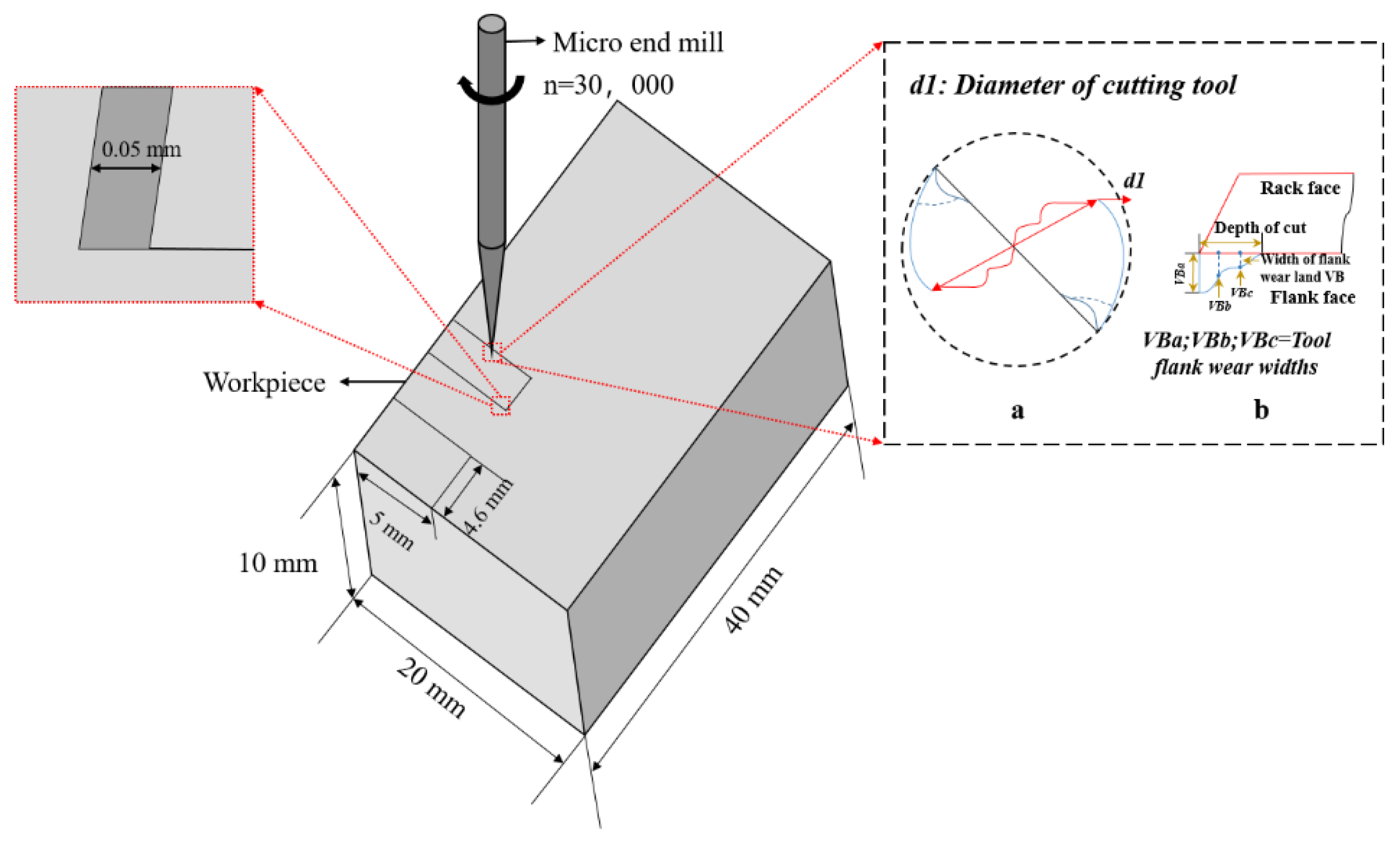
2. Materials and Methods
3. Results
3.1. End Face Wear
3.2. Flank Wear
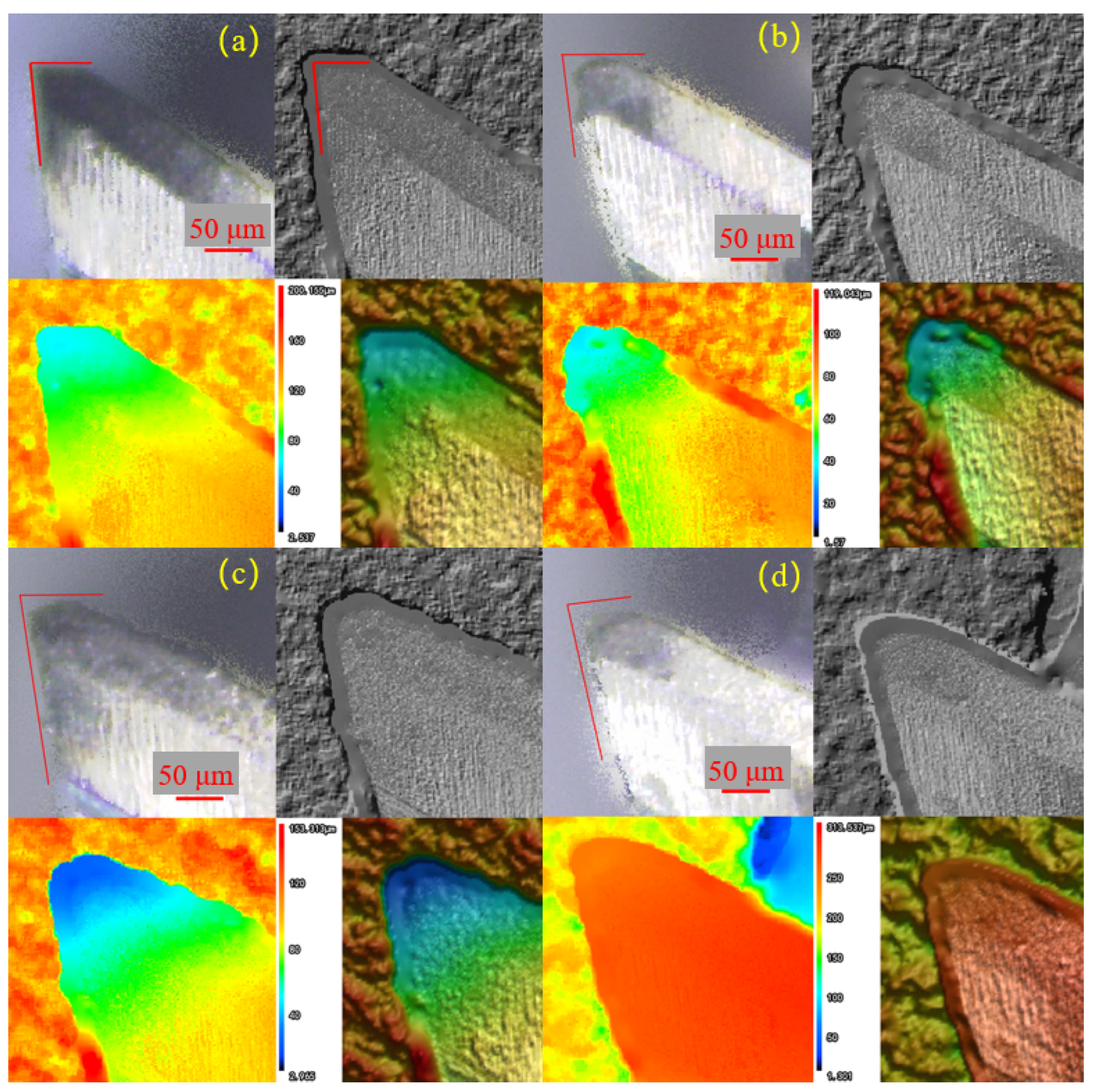
3.3. Edge Radius
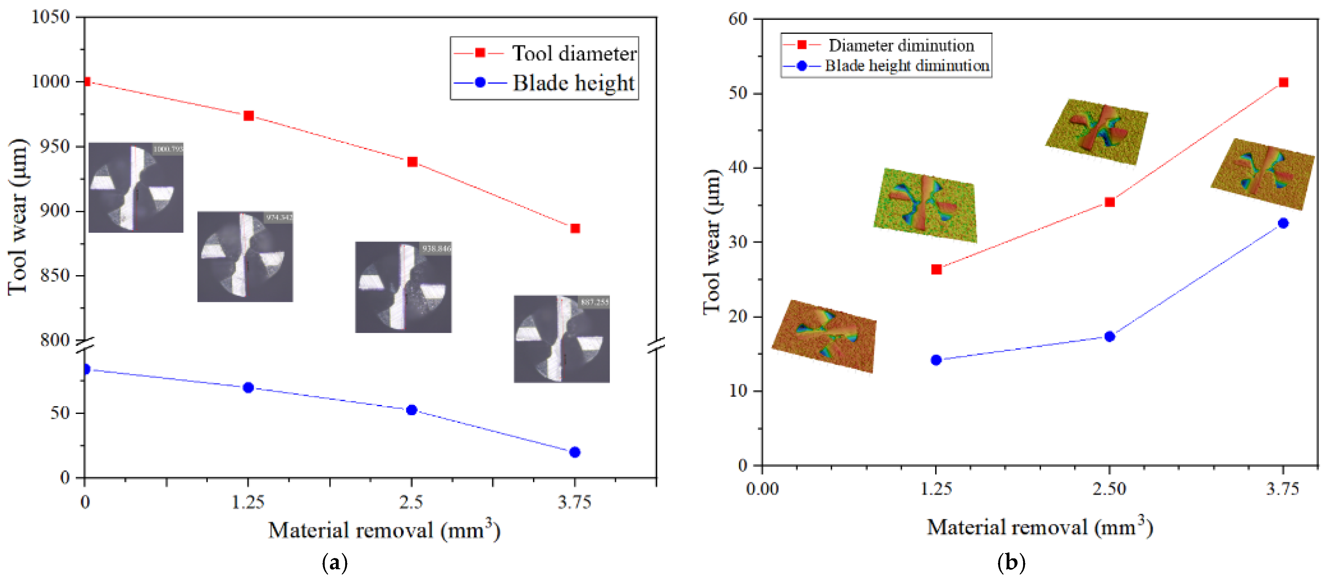
3.4. Tool Diameter Reduction
3.5. Tool Wear Mechanisms
4. Conclusions
- The wear modes are classified into progressive normal wear failure and abnormal wear failure. The progressive normal wear failure mainly includes abrasion marks, material adhesion, built-up edges (BUE) and micro-blade collapse, while the abnormal wear failure mainly includes severe plastic deformation, blade collapse, catastrophic fracture and delamination of the cutting edge. Due to the micron size, the influence of BUE is amplified and plays a leading role in cutting performance.
- There is no relevant international standard for the wear of a micro-milling cutter. According to the characteristics of micro milling, a comprehensive analysis was conducted from the aspects of end face wear, flank wear, edge diameter reduction and edge radius. The wear of end face 30 μm, wear of flank 35 μm and tool diameter reduction 55 μm can be used as the failure criteria of a micro-milling cutter. Tool wear makes the edge radius increase gradually, which seriously affects the cutting performance of a micro-milling cutter.
- The wear process and wear mechanism of micro-milling cutter machining are analyzed. Adhesive wear exists in the whole cutting process and plays a major role. High temperature, element concentration gradient and oxygen provide conditions for abrasive particle shedding, element diffusion and oxidation reaction. Abrasive wear, diffusion wear and oxidation wear occur only when the cutting temperature reaches the melting point of Co, and oxidation wear aggravates the failure of the binder and the peeling off of tool particles.
Author Contributions
Funding
Institutional Review Board Statement
Informed Consent Statement
Data Availability Statement
Conflicts of Interest
References
- Hoyle, R. Developments in micro and nano engineering and manufacturing. Plas. Rub. Comp. 2008, 37, 50–56. [Google Scholar] [CrossRef]
- Dhanorker, A.; Ozel, T. Meso/micro scale milling for micro-manufacturing. Int. J. Mech. Manuf. Syst. 2008, 1, 23–42. [Google Scholar] [CrossRef]
- Iqbal, A.; Zhao, G.; Zaini, J.; Gupta, M.K.; Jamil, M.; He, N.; Nauman, M.M.; Mikolajczyk, T.; Pimenov, D.Y. Between-the-holes cryogenic cooling of the tool in hole-making of Ti-6Al-4V and CFRP. Materials 2021, 14, 795. [Google Scholar] [CrossRef]
- Sen, B.; Gupta, M.K.; Mia, M.; Pimenov, D.Y.; Mikołajczyk, T. Performance assessment of minimum quantity castor-palm oil mixtures in hard-milling operation. Materials 2021, 14, 198. [Google Scholar] [CrossRef] [PubMed]
- Jamil, M.; Khan, A.M.; Hegab, H.; Gong, L.; Mia, M.; Gupta, M.K. Effects of hybrid Al2O3-CNT nanofluids and cryogenic cooling on machining of Ti–6Al–4V. Int. J. Adv. Manuf. Technol. 2019, 102, 3895–3909. [Google Scholar] [CrossRef]
- Pimenov, D.Y.; Mia, M.; Gupta, M.K.; Machado, A.R.; Tomaz, I.V.; Sarikaya, M.; Wojciechowski, S.; Mikolajczyk, T.; Kaplonek, W. Improvement of machinability of Ti and its alloys using cooling-lubrication techniques: A review and future prospect. J. Mater. Res. Technol.-JMRT. 2021, 11, 719–753. [Google Scholar] [CrossRef]
- Adebiyi, D.I.; Popoola, A.P.I. Mitigation of abrasive wear damage of Ti-6Al-4V by laser surface alloying. Mater. Des. 2015, 74, 67–75. [Google Scholar] [CrossRef]
- Wang, C.Y.; Xie, Y.X.; Qin, Z.; Lin, H.S.; Yuan, Y.H.; Wang, Q.M. Wear and breakage of TiAlN-and TiSiN-coated carbide tools during high-speed milling of hardened steel. Wear. 2015, 336, 29–42. [Google Scholar] [CrossRef]
- Aslantas, K.; Hopa, H.E.; Percin, M.; Ucun, I.; Çicek, A. Cutting performance of nano-crystalline diamond (NCD) coating in micro-milling of Ti6Al4V alloy. Precis. Eng. 2016, 45, 55–66. [Google Scholar] [CrossRef]
- International Standards Organisation. ISO 8688-1; Tool Life Testing in Milling—Part 1: Face Milling. ISO: Geneva, Switzerland, 1989. [Google Scholar]
- International Standards Organisation. ISO 8688-2; Tool Life Testing in Milling—Part 2: End Milling. ISO: Geneva, Switzerland, 1989. [Google Scholar]
- Lai, X.; Li, H.; Li, C.; Lin, Z.; Ni, J. Modelling and analysis of micro scale milling considering size effect, micro cutter edge radius and minimum chip thickness. Int. J. Mach. Tools. Manuf. 2008, 48, 1–14. [Google Scholar] [CrossRef]
- Liu, X.; Devor, R.E.; Kapoor, S.G. An analytical model for the prediction of minimum chip thickness in microm-achining. J. Manuf. Sci. Eng. 2006, 128, 474–481. [Google Scholar] [CrossRef]
- Zhu, K.; Yu, X. The monitoring of micro milling tool wear conditions by wear area estimation. Mech. Syst. Sign. Pro. 2017, 93, 80–91. [Google Scholar] [CrossRef]
- Alhadeff, L.L.; Marshall, M.B.; Curtis, D.T.; Slatter, T. Protocol for tool wear measurement in micro-milling. Wear 2018, 420, 54–67. [Google Scholar] [CrossRef]
- Han, J.J.; Ma, R.; Hao, X.Q.; Kong, L.L.; Chen, N. Experimental research on deep-and-narrow micromilled grooves using a self-fabricated PCD micro-cutter. Micromachines 2021, 12, 1170. [Google Scholar] [CrossRef]
- Manso, C.S.; Thom, S.; Uhlmann, E.; Assis, C.L.F.; Conte, E.G. Tool wear modelling using micro tool diam-eter reduction for micro-end-milling of tool steel H13. Int. J. Adv. Manuf. Technol. 2019, 105, 2531–2542. [Google Scholar] [CrossRef]
- Ziberov, M.; Da Silva, M.B.; Jackson, M.; Hung, W.N.P. Effect of cutting fluid on micromilling of Ti-6Al-4V titanium alloy. Procedia Manuf. 2016, 5, 332–347. [Google Scholar] [CrossRef] [Green Version]
- Dadgari, A.; Huo, D.; Swailes, D. Investigation on tool wear and tool life prediction in micro-milling of Ti-6Al-4V. Nano-Technol. Precis. Eng. 2018, 1, 218–225. [Google Scholar] [CrossRef]
- Oliaei, S.N.; Karpat, Y. Influence of tool wear on machining forces and tool deflections during micro milling. Int. J. Adv. Manuf. Technol. 2015, 84, 1963–1980. [Google Scholar] [CrossRef] [Green Version]
- Silva, E.L.; Pratas, S.; Neto, M.A.; Fernandes, C.M.; Figueiredo, D. Multilayer diamond coatings applied to micro-end-milling of cemented carbide. Materials 2021, 14, 3333. [Google Scholar] [CrossRef]
- Muhammad, A.; Kumar Gupta, M.; Mikołajczyk, T.; Pimenov, D.Y.; Giasin, K. Effect of tool coating and cutting parameters on surface roughness and burr formation during micromilling of inconel 718. Metals 2021, 11, 167. [Google Scholar] [CrossRef]
- Wang, Y.; Zou, B.; Wang, J.; Wu, Y.; Huang, C. Effect of the progressive tool wear on surface topography and chip formation in micro-milling of Ti–6Al–4V using Ti(C7N3)-based cermet micro-mill. Tribol. Int. 2020, 141, 105900. [Google Scholar] [CrossRef]
- Sahoo, P.; Patra, K.; Pimenov, D.Y. Enhancement of micro milling performance by abrasion-resistant coated tools with optimized thin-film thickness: Analytical and experimental characterization. Int. J. Adv. Manuf. Technol. 2022. [Google Scholar] [CrossRef]
- Varghese, A.; Kulkarni, V.; Joshi, S.S. Tool life stage prediction in micro-milling from force signal analysis using machine learning methods. ASME J. Manuf. Sci. Eng. 2020, 143, 054501. [Google Scholar] [CrossRef]
- Saha, S.; Deb, S.; Bandyopadhyay, P.P. Progressive wear based tool failure analysis during dry and MQL assisted sustainable micro-milling. Int. J. Mech. Sci. 2021, 212, 106844. [Google Scholar] [CrossRef]
- Jaffery, S.H.I.; Mativenga, P.T. Wear mechanisms analysis for turning Ti-6Al-4V-towards the development of suita-ble tool coatings. Int. J. Adv. Manuf. Technol. 2012, 58, 479–493. [Google Scholar] [CrossRef]
- Sarıkaya, M.; Gupta, M.K.; Tomaz, I.; Pimenov, D.Y.; Kuntoğlu, M.; Khanna, N.; Yıldırım, Ç.V.; Krolczyk, G.M. A state-of-the-art review on tool wear and surface integrity characteristics in machining of superalloys. CIRP J. Manuf. Sci. Technol. 2021, 35, 624–658. [Google Scholar] [CrossRef]
- Thakur, D.G.; Ramamoorthy, B.; Vijayaraghavan, L. Some investigations on high speed dry machining of aerospace material Inconel 718 using multicoated carbide inserts. Adv. Manuf. Prof. 2012, 10, 1066–1072. [Google Scholar] [CrossRef]
- Qi, G.; Guangyan, G.; Ming, C. Wear mechanism and experimental study of a tool used for micro-milling sin-gle-crystal nickel-based superalloys. Int. J. Adv. Manuf. Technol. 2021, 113, 117–129. [Google Scholar] [CrossRef]
- Zhang, J.F.; Feng, C.; Wang, H.; Gao, Y.D. Analytical investigation of the micro groove surface topography by micro-milling. Micromachines 2019, 10, 582. [Google Scholar] [CrossRef] [Green Version]
- Aslantas, K.; Ülker, Ş.; Şahan, Ö.; Pimenov, D.Y.; Giasin, K. Mechanistic modeling of cutting forces in high-speed microturning of titanium alloy with consideration of nose radius. Int. J. Adv. Manuf. Technol. 2022, 119, 2393–2408. [Google Scholar] [CrossRef]


| Elements | Al | V | Fe | O | N | C | H | Ti |
|---|---|---|---|---|---|---|---|---|
| Content (Wt. %) | 5.5 | 4.2 | 0.22 | 0.11 | 0.03 | 0.08 | 0.012 | 89.848 |
| Cutting Edge Diameter (D) | Cutting Edge Length (l) | Cutter Length (L) | Tilt Angle (γ°) | The Handle Diameter (d) |
|---|---|---|---|---|
| 1 mm | 3 mm | 50 mm | 30 | 4 mm |
| Rotating Speed (n) | Feed Speed (Vf) | Cutting Depth (ap) |
|---|---|---|
| 20,000/25,000/30,000 rpm | 5 mm/min | 0.05 mm |
Publisher’s Note: MDPI stays neutral with regard to jurisdictional claims in published maps and institutional affiliations. |
© 2022 by the authors. Licensee MDPI, Basel, Switzerland. This article is an open access article distributed under the terms and conditions of the Creative Commons Attribution (CC BY) license (https://creativecommons.org/licenses/by/4.0/).
Share and Cite
Zheng, T.; Song, Q.; Du, Y.; Liu, Z. Development of Tool Wear Standards and Wear Mechanism for Micro Milling Ti-6Al-4V Alloy. Metals 2022, 12, 726. https://doi.org/10.3390/met12050726
Zheng T, Song Q, Du Y, Liu Z. Development of Tool Wear Standards and Wear Mechanism for Micro Milling Ti-6Al-4V Alloy. Metals. 2022; 12(5):726. https://doi.org/10.3390/met12050726
Chicago/Turabian StyleZheng, Tao, Qinghua Song, Yicong Du, and Zhanqiang Liu. 2022. "Development of Tool Wear Standards and Wear Mechanism for Micro Milling Ti-6Al-4V Alloy" Metals 12, no. 5: 726. https://doi.org/10.3390/met12050726