Review

Review of Thermoplastic Drawing with Bulk Metallic Glasses

1
Department of Mechanical Engineering, The University of Texas at Dallas, Richardson, TX 75080, USA
2
College of Engineering, Zhejiang Normal University, Jinhua 321000, China
3
Department of Mechanical Engineering, The University of Texas Permian Basin, Odessa, TX 79762, USA
*
Author to whom correspondence should be addressed.
Metals 2022, 12(3), 518; https://doi.org/10.3390/met12030518
Submission received: 29 December 2021 / Revised: 20 February 2022 / Accepted: 16 March 2022 / Published: 18 March 2022
(This article belongs to the Topic Advanced Forming Technology of Metallic Materials)

Abstract

:
This study summarizes the recent progress in thermoplastic drawing of bulk metallic glasses. The integration of drawing with templated embossing enables the fabrication of arrays of high-aspect-ratio nanostructures whereas the earlier drawing methodologies are limited to a single fiber. The two-step drawing can produce metallic glass structures such as, vertically aligned nanowires on substrates, nanoscale tensile specimens, hollow microneedles, helical shafts, and micro-yarns, which are challenging to fabricate with other thermoplastic forming operations. These geometries will open new applications for bulk metallic glasses in the areas of sensors, optical absorption, transdermal drug-delivery, and high-throughput characterization of size-effects. In this article, we review the emergence of template-based thermoplastic drawing in bulk metallic glasses. The review focuses on the development of experimental set-up, the quantitative description of drawing process, and the versatility of drawing methodology.

Graphical Abstract

1. Introduction

Bulk metallic glasses (BMGs) are metal-based alloys prepared in an amorphous state by rapid cooling or other non-equilibrium processing techniques [1,2,3,4,5]. The glass forming compositions are designed based on the atomic size, the phase diagrams, and the thermodynamic data to suppress the crystal formation [2,3,6,7,8,9,10,11,12]. New alloys with improved glass forming ability and properties are continuously being discovered using advanced experimental and computational methodologies [13,14,15,16,17,18]. Amorphous structure endows BMGs with unique mechanical, thermal, and chemical properties. BMGs display high strength and elastic strain limit due to the absence of crystal defects but fail along localized shear bands with little global plasticity [19,20,21,22,23,24,25]. The noncrystalline structure also improves wear and corrosion resistance and lowers friction in BMGs [26,27,28,29,30,31]. Several BMGs are tailored for specific functional properties such as biocompatibility [32,33,34,35,36], biodegradability [37,38,39], catalytic activity [40,41,42,43,44,45], and ferromagnetism [46,47,48,49].
The industrial applications of BMGs have remained limited despite spanning a wide range of compositions and properties. High material cost, limited plasticity, and incompatibility with conventional machining operations are the main factors that prevent commercialization of BMGs. To overcome these issues, the research efforts have been redirected towards small-scale applications that require less material and can benefit from the enhanced plasticity of BMGs with decreasing sample size [50,51,52,53,54,55,56]. However, the manufacturing challenges are exacerbated at these length scales. High hardness and lack of plasticity impede the machining of precise microparts from as-cast BMG feedstocks [53]. The direct casting of net-shaped BMG components requires concomitant filling of mold cavities and fast cooling to avoid crystallization [57,58]. This process is reliable only for simple geometries such as plates or rods. Therefore, alternative manufacturing routes are desired to make BMG micro and nanostructures.
One of the processing techniques that shows great potential for BMGs is inspired by thermoplastic polymers. BMGs soften into a metastable supercooled liquid state above the glass transition temperature (Tg) before devitrification into the stable crystalline state. The BMG compositions are specifically designed to resist crystallization and retain the metastable liquid state over a wide temperature range [2]. Controllable viscosities in the range 1010–106 Pa·s can be accessed for several minutes at moderate temperatures in many BMG supercooled liquids [59,60,61,62,63,64]. Owing to these unique characteristics, the viscous state of BMGs has attracted increasing attention for thermoplastic forming operations [52,57,65,66,67,68,69,70,71,72,73,74,75,76,77,78,79]. Rapid cooling is not required to prevent crystallization after thermoplastic forming which makes this processing route particularly attractive compared to direct casting of BMG parts from the liquid state. A plethora of thermoplastic fabrication techniques such as extrusion [65,70], rolling [69], joining [75,80,81], blow-molding [73,82], and embossing [52,57,66] have been developed to produce diverse BMG parts. The common feature of all these methods is heating the BMG above its Tg and applying the pressure. Embossing against predefined templates can generate micro and nanoscale features on BMG surfaces with high precision [68,71,74,76]. The ability to form metal nanostructures by embossing has opened a broad range of applications for BMGs such as fuel-cell catalysts [42,43,44], sensors [83], optical absorption [68,84,85,86], and hydrophobic surfaces [76,87,88,89,90]. However, thermoplastic embossing of BMGs faces some inherent challenges that can be overcome by thermoplastic drawing as discussed in the following section.
The concept of fiber drawing is well-known in oxide and polymeric glasses and has been applied to BMGs. Kawamura et al. performed a series of high-temperature tensile tests on Pd-based and La-based BMGs and observed large elongations [91,92]. Subsequently, many other groups reported strain-rate dependent Newtonian flow and superplasticity in BMG supercooled liquids [93,94,95,96,97]. Inoue et al. [98] and Nieh et al. [99] used the high-temperature viscous flow of BMGs to fabricate long microwires by stretching the cylindrical rods by more than 15,000%. The potential of wire drawing remained largely unexplored in BMGs until Yi et al. demonstrated the formation of nanoscale fibers by pulling the metallic glass forming liquid at very high temperatures [100]. They used an induction heating of BMG feedstock while applying a tensile load by hanging a weight. A long wire is drawn under the tensile load when the viscosity of BMG supercooled liquid drops to a sufficiently low value. The technique has been used to fabricate very high-aspect-ratio BMG micro and nanofibers [100]. The formation of nanoscale structures without focused-ion-beam has generated significant interest in characterization of size-effects in mechanical properties of BMGs [101,102,103]. Two excellent reviews on drawing of BMG fibers and their properties and applications have been published [104,105]. Although, the previous drawing methodologies can generate BMG nanofibers, they are limited to a single fiber per experiment. Many potential applications such as, catalysts, sensors, and composites require large quantities of dispersed metal nanostructures. The use of templates in thermoplastic drawing described in this review offers a unique advantage in high-throughput manufacturing of arrays of nanostructures. In addition, the BMG nanofibers drawn from a template are vertically aligned on a substrate, and therefore are directly suitable for integration in devices.

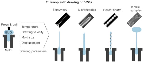
2. Thermoplastic Drawing versus Embossing

Figure 1 illustrates the thermoplastic embossing and drawing processes used for the manufacturing of BMG micro and nanostructures. A rigid mold made from materials such as silicon, alumina, metals, or glass is used to withstand the embossing pressure and temperature (above Tg). The mold is placed on a heating plate and a piece of BMG is pressed between the mold and another heating plate (Figure 1).
The BMG supercooled liquid conforms to the mold cavities under pressure. In embossing studies, the mold and the BMG are cooled to room temperature after pressing [52,57,66]. The mold is dissolved in chemicals to release the BMG structures and a new mold is required for every operation. However, in thermoplastic drawing the BMG and the mold are mechanically pulled apart after pressing while maintaining the temperature above Tg [106]. Depending on the pulling velocity and the processing temperature, either complete demolding or elongation of BMG structures is observed [106,107,108]. The demolding allows reusability of the mold whereas elongation can be harnessed in making the structures that are challenging to fabricate by embossing. The majority of previous thermoplastic processing studies on BMGs have been focused on embossing because of its ease of implementation [52,57,66]. The main limitations of embossing are the use of sacrificial molds and the inability to produce high-aspect-ratio nanostructures. The mold cost increases with decreasing size or increasing aspect-ratio of features. Therefore, sacrificial molds are not practical for the fabrication of nanoscale BMG structures by thermoplastic embossing. Furthermore, the embossing pressure scales with the square of the aspect-ratio, limiting the length of BMG nanowires or nanotubes made by embossing [56,58]. These challenges are alleviated in thermoplastic drawing which relies on downsizing of large structures by applying a small tensile force [106,108].
Thermoplastic embossing set-up is relatively simple consisting of two flat heating plates mounted on a universal testing system (UTS). The UTS allows control over the compressive force and the rate of displacement which is critical for reproducible embossing. However, the template-based thermoplastic drawing is a two-step process, which involves pressing and pulling. Implementation of pulling requires modification to the heating plates used for embossing. The plates should be capable of gripping the mold and the BMG in order to apply a pulling force after pressing. This becomes particularly challenging as the BMG flattens into a thin disc during the pressing stage. We designed two detachable fixtures for the heating plates to secure the BMG and the mold for tensile loading (Figure 2). The top fixture consists of a plunger and the bottom fixture contains a recessed cavity (Figure 2a). A commercially available metal mesh was wrapped around the plunger (Figure 2b) while the mold was firmly secured in the lower fixture cavity (Figure 2c). These custom-made fixtures allow the application of compressive and tensile loads to the BMGs heated in the supercooled liquid state. The top side of BMG flows into the metal mesh while the lower side fills the mold cavities during embossing. The BMG disc strongly attaches to the metal mesh and moves with the plunger during subsequent pulling. Depending upon the pulling velocity and the processing temperature, either elongation of BMG structures or complete separation from the mold can be observed. It should be noted that the BMG disc may stick to the mold if the anchoring with the metal mesh is weak. The following sections assume that the BMG disc strongly attaches to the mesh-plunger system and the pulling only affects the BMG mold interface.

3. Fiber Drawing Kinetics

The outcome of BMG thermoplastic drawing is governed by the processing temperature and the pulling velocity which affect the viscosity and the strain-rate, respectively. As illustrated in Figure 3a, stable fiber drawing requires an optimal combination of temperature and pulling velocity. At low temperature (or high pulling velocity), the BMG demolds from the mold cavity because its flow stress exceeds the adhesive strength with the mold [107]. With increasing temperature (or decreasing pulling velocity), the BMG adheres to the mold surface and results in drawing of a viscous filament from BMG reservoir (Figure 3a). At a very high temperature (or slow pulling velocity), the liquid filament rapidly thins and breaks due to capillary stress. This results in the formation of short BMG fibers with sharp tips. The length of BMG fibers can be increased by decreasing the processing temperature and/or by increasing the pulling velocity while still preventing demolding. A long and uniform BMG fiber can be drawn by optimizing the drawing conditions. Furthermore, the drawing can be stopped prior to breakup to control the length and the diameter of the drawn fiber.
The effects of drawing temperature and velocity on BMG fiber can be described by comparing the viscous and the capillary stresses acting on the liquid filament. These effects can be quantified by using dimensionless capillary number (Ca):
C a = v i s c o u s   s t r e s s c a p i l l a r y   s t r e s s = η v / L γ / D
where η is the BMG viscosity, v is the pulling velocity, L is the instantaneous length of BMG fiber, γ is the BMG surface tension, and D is the smallest fiber diameter. The viscous resistance counters the thinning induced by the surface tension. Therefore, higher Ca favors the formation of long and uniform fiber whereas lower Ca results in necking and early breakup. The Ca decreases during drawing and the BMG fiber breaks up below a critical Ca of about 0.1 [108]. The final breakup of elongating BMG fiber in the supercooled liquid state is always caused by the capillary induced necking. The data from the temperature and the velocity experiments can be combined to construct a drawing map as shown in Figure 3b. The decrease in processing temperature or increase in drawing velocity has the same effect on the length of BMG fiber. Both promote the formation of long BMG fibers by delaying the necking instability and rupture.
It is important to quantify the BMG fiber evolution to make the thermoplastic drawing a reproducible process. Besides temperature and pulling velocity, the vertical displacement and the mold dimensions also affect the drawn BMG fiber. To determine the minimum fiber diameter (Dmin), the drawing length (L) and the diameter of the cylindrical mold cavity (Do) were independently varied in drawing experiments using Pt-BMG (Figure 4). The temperature and the pulling velocity were kept constant and the drawing was stopped before the fiber breakup. Figure 4a,b show the effects of varying L and Do, respectively. The SEM images of representative specimens show the formation of uniform and smooth BMG fibers. The minimum diameter Dmin decreases with increasing L or decreasing Do. The results demonstrate that the BMG fibers with nanoscale diameters can be drawn without using expensive lithographic molds. The smaller mold diameter is more effective in drawing nanoscale BMG fibers compared to increasing the length because of different fluid volumes. We also observed that higher temperature and lower drawing velocity promote large reduction in BMG fiber diameter by decreasing the active fluid volume [108].
The evolution of fiber diameter can be quantitatively described using a numerical solution of lubrication problem involving the viscous and the capillary stresses. Alternatively, an approximate analytical expression can be used to predict Dmin:
D m i n D o ( π α L D o + 2 ) ( 1 L L B )
This approximation is obtained by combining the results of a purely viscous lubrication analysis with the similarity solution to account for the capillary effect [108]. Here, α is a fitting parameter and LB is the fiber length at capillary induced breakup. As shown in Figure 4, Equation (2) describes the variation in Dmin as a function of L and Do reasonably well. The quantitative correlation makes the thermoplastic drawing-based manufacturing of BMGs more controllable and reproducible.

4. High-Aspect-Ratio Structures

Long metal structures are desired to enhance the surface area and to characterize the properties such as mechanical, thermal, and electrical. BMG structures with aspect ratio (length/diameter) higher than 10 require impractically high embossing force which is not applicable to fragile molds made by lithography. In contrast, thermoplastic drawing requires only small tensile force which decreases with increasing length because of reduction in cross-sectional area. Therefore, BMG structures of any length can be drawn by preventing the fracture. As discussed in the preceding section, the fracture of elongating viscous BMG is caused by the surface tension induced capillary stress. The fracture can be delayed by decreasing the processing temperature and by increasing the pulling velocity as predicted by Equation (1) and illustrated in the deformation map (Figure 3b). Figure 5 shows the SEM images of very long Pt-BMG microfibers made by lowering the processing temperature and increasing the pulling velocity. An array of BMG fibers with diameters in the range of 10–20 μm and aspect-ratios exceeding 200 could be reproducibly drawn using perforated steel mesh with 200 μm holes as a mold (Figure 5a,b). The processing temperature was lowered from 270 °C to 265 °C and the pulling velocity was increased from 10 mm/min to 20 mm/min. The drawing was continued until the fiber fractured by necking. The variation in the length of BMG fibers is less than 20% despite the stochastic nature of the final breakup. Figure 5c shows a single BMG microwire with a uniform diameter of about 4 μm drawn from a cavity machined in an aluminum mold. Such uniform structures are directly suitable for the measurement of stress–strain behavior or electrical transport properties. The experimental results clearly show that thermoplastic drawing is capable of producing high aspect-ratio BMG structures.
Applications such as sensors and catalysts require further enhancement in metal surface area which is attainable only in nanowires and nanotubes. As discussed in Section 3, BMG structures can be downsized to nanoscale by choosing an optimal combination of mold size and pulling length (Figure 4). The 200 µm diameter structure requires pulling length of about 20 mm whereas 100 µm diameter structure reduces to sub-micron scale only after pulling length of 3 mm (Figure 4). These observations suggest that smaller mold cavities should be used to achieve the smallest size in drawn BMGs. Figure 6 shows the use of lithographically fabricated Si molds with microscale cavities to form an array of high-aspect-ratio Pt-BMG nanostructures.
Nanowires (NWs) with diameters in the range of 100 nm were drawn from 20 µm diameter holes (Figure 6a). BMG nanotubes (NTs) can be drawn by using Si mold with tubular cavities (Figure 6b). A hollow cross-section is retained during elongation. BMG NWs and NTs with aspect-ratios exceeding 500 can be readily fabricated by drawing. Two sets of nanostructures are formed after fracture, one remains attached to the BMG disc and the second is anchored to the Si mold. The density and layout of BMG NWs and NTs can be controlled by changing the Si mold. Similar nanostructures are not feasible by thermoplastic embossing because of high pressure requirements.

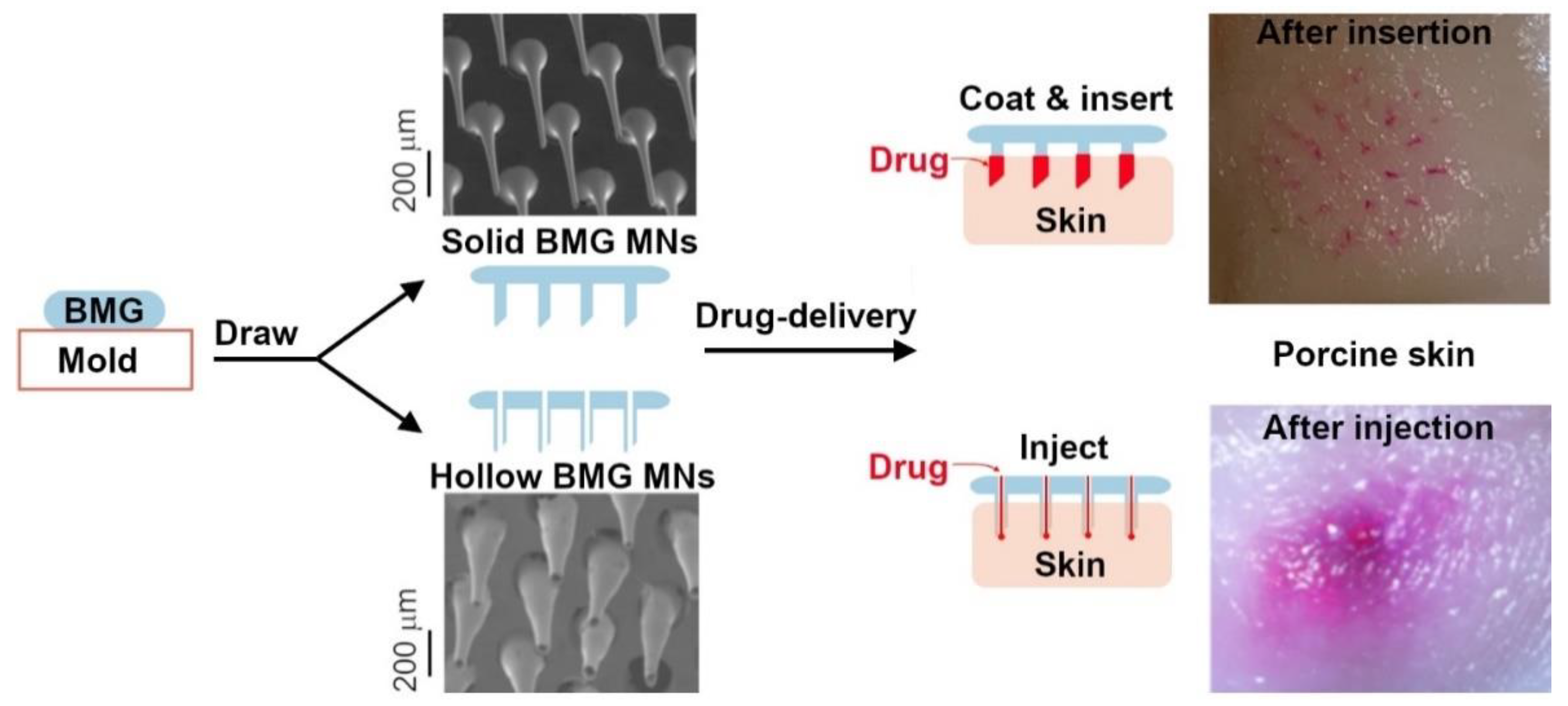
5. Microneedles for Drug-Delivery

Solid and hollow microneedles (MNs) are envisioned as an alternative to hypodermic injections for painless delivery of pharmaceuticals, particularly the compounds which are not suitable for oral consumption [109,110]. The transdermal MNs should be able to withstand the skin insertion force without mechanical failure and should be made from non-toxic materials. Metals are good candidates for MNs because of their high resistance to elastic buckling and plastic deformation. However, fabrication techniques for metal MNs are often complex and sequential, particularly for hollow MNs. These challenges can be overcome by using BMG MNs made by thermoplastic drawing [111]. BMGs exhibit high strength and stiffness, and their composition can be tailored for biocompatibility [32]. Thermoplastic drawing conditions can be optimized to control the geometry and dimensions of BMG microfibers suitable for MNs. Figure 7 illustrates the concept of using BMG MNs for transdermal drug-delivery applications.
Solid or hollow BMG MNs can be drawn by selecting a suitable mold, i.e., cylindrical or tubular. Alternatively, both solid and hollow MNs can also be drawn from the same cylindrical mold by controlling the thickness of BMG [112]. The SEM images show examples of solid and hollow Pt-BMG MNs produced by thermoplastic drawings (Figure 7). The images of porcine skin after insertion (Figure 7) show the capability of Pt-BMG to deliver a model drug (sulforhodamine fluorescent dye). The solid BMG MNs were coated with the drug by dip-coating whereas the hollow BMG MNs were filled with the drug solution. The BMG MNs remained mechanically intact after insertion owing to their high elastic modulus and tapered profile. Furthermore, the tip shape of drawn BMG structures can also be varied between conical or bevel to mimic the conventional MNs used for drug delivery. Besides drug delivery, metal MNs are also desirable for other biomedical applications such as cosmetics, fluid extraction, and neural electrodes. These applications can significantly benefit from the thermoplastic drawing of BMG micro and nanofibers.

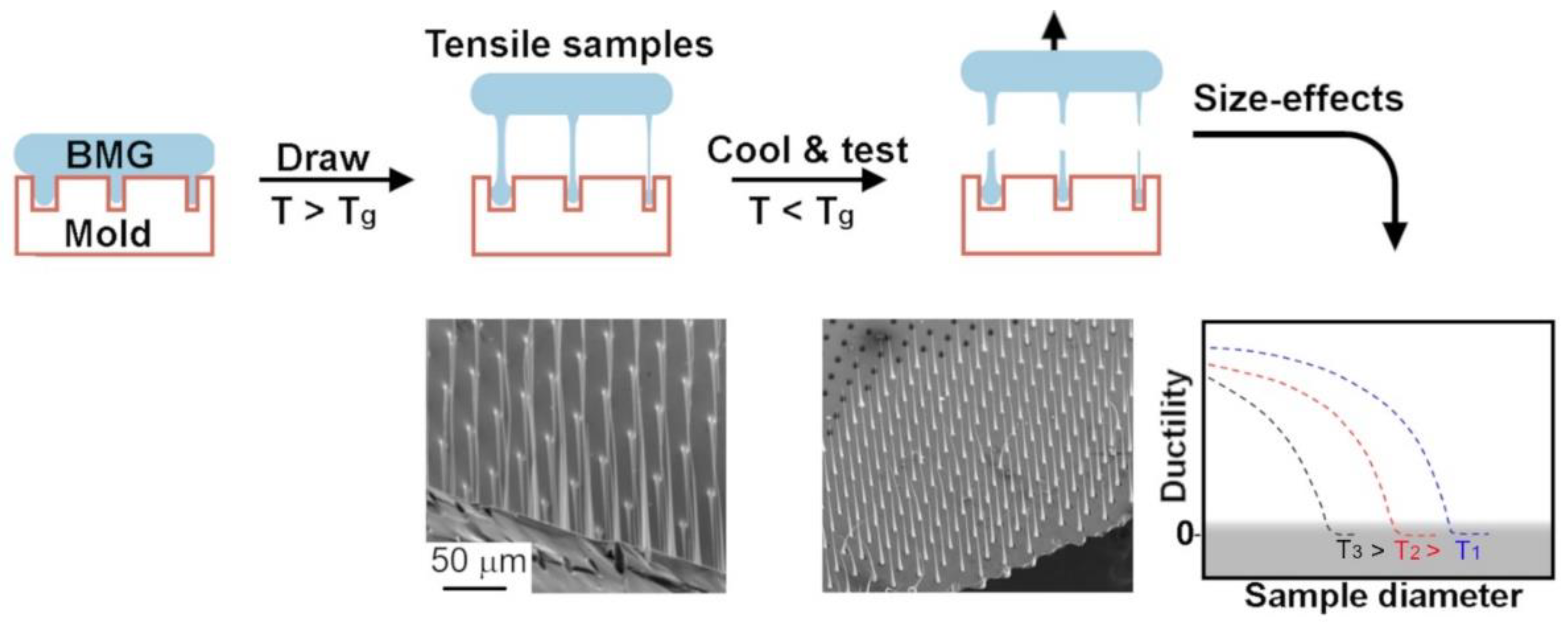
6. Nanoscale Tensile Specimens
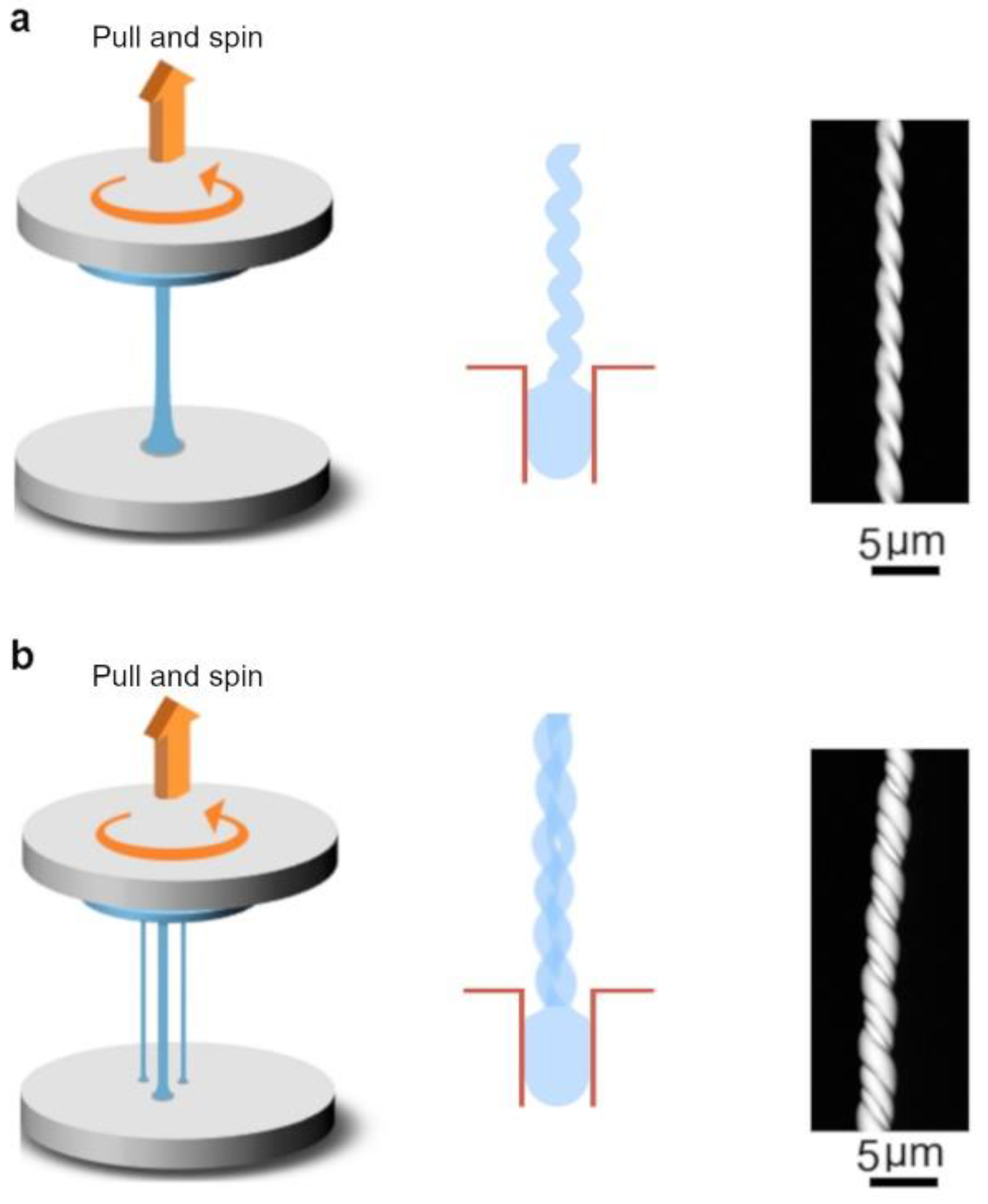
Size-effects in the mechanical behavior of BMGs have gained increasing interest due to their potential in improving ductility [113,114,115,116,117]. Nanoscale BMGs have been reported to exhibit enhanced ductility compared to the macroscopic counterparts which fail catastrophically by forming localized shear bands. Numerous studies have been focused on small-scale BMGs but the existence and the mechanism of size-dependent ductility remain controversial [102,113,114,115,116,117,118,119,120,121,122,123]. The main causes of discrepancy in reported data are the irradiation damage due to the use of focused-ion-beam (FIB) in sample preparation and a limited number of mechanical tests owing to complex in situ testing [102,121,123]. Thermoplastic drawing of BMGs can eliminate these concerns by enabling high-throughput fabrication and mechanical testing of specimens without FIB (Figure 8). During drawing, the BMG filament inherently transforms into dog-bone shaped geometry which can be preserved by cooling below Tg for subsequent tensile testing [108,124]. The sample diameter is tunable by changing the drawing length and the mold size. The samples with varying diameters can be simultaneously drawn by using a mold with different sized cavities as illustrated in Figure 8.
This approach produces irradiation-free samples and minimizes the variation in the glassy state among samples of different diameters. The drawn samples are anchored between the mold and the BMG disc that can serve as tensile grips for loading. Multiple samples of each diameter can be fabricated and tested to yield statistically reliable experimental data. The tensile test can also be performed at different temperatures by cooling the drawn samples to the desired temperature (Figure 8). This can provide additional valuable information to test the existing hypotheses. For example, we observed that the size-dependent transition from brittle to ductile tensile failure in Pt-BMG specimens shifts to a larger size with decreasing testing temperatures (Figure 8). These findings strongly hint towards a thermally driven shear banding process in BMGs [124]. To obtain comparable information from individual in situ nanomechanical tests is expensive and prone to significant errors. Therefore, the combination of damage-free fabrication, testing of multiple samples, and incorporation of temperature effect can facilitate understanding the mechanism of intrinsic size-effects in the mechanical behavior of BMGs.

7. Hybrid Drawing

The results from the uniaxial thermoplastic drawing of BMGs demonstrate that such a process is controllable and scalable to multiple fibers. The shape and size of drawn fibers can be predicted using the analytical model based on the properties of BMG supercooled liquid and the drawing parameters. The drawing technique is not limited to uniaxial pulling but many other variants are feasible to advance a more versatile BMG manufacturing. Here, we show results from two such modifications to enable the fabrication of challenging BMG geometries. A constant pulling velocity can only produce a certain combination of fiber shape and size. This restriction can be overcome by applying a variable pulling velocity. Figure 9 shows an example of Pt-BMG subjected to step change (up and down) in pulling velocity. In the first case, the pulling velocity was increased from 1 to 60 mm/min which generated a very high aspect ratio (>1000) BMG nanowire (Figure 9a). Initial slow drawing caused rapid thinning under increasing capillary stress. Subsequently, the process transitioned to uniform drawing due to increase in capillary number caused by higher pulling velocity. Similarly, a sudden decrease in pulling velocity from 60 to 1 mm/min resulted in the formation of BMG microwire with nanoscale tip (Figure 9b). The uniform microwire was necked and ruptured by a decrease in capillary number. Similarly, the processing temperature can be changed during the drawing to generate structurally gradient BMG fibers.
In another variant, rotational and axial motions were superimposed during the thermoplastic drawing to create helical BMG fibers (Figure 10). A combination of rotation and drawing yields twisted BMG microfiber with a periodic thread (Figure 10a). The spinning and drawing velocities can be independently controlled to tailor the thread spacing and the fiber diameter. Similarly, threaded metal shafts with sub-10-micron diameters are challenging to fabricate by conventional machining processes. The spinning and drawing methodology can also be applied to multiple fibers to create a rope-like BMG structure as shown in Figure 10b. Three Pt-BMG fibers were drawn and spun to produce BMG micro-yarn. It is of particular interest to evaluate if nanoscale and microscale fibers can be combined to harness the size-effects in ductility and strength.

8. Drawing of Oxidizing BMGs

The thermoplastic drawing results shown so far are all from Pt-BMG which is relatively inert. However, many BMGs such as Pd-BMG, Zr-BMG and Mg-BMG readily oxidize when heated in the supercooled liquid temperature range in air [63]. The formation of an oxide layer as thick as 10–150 nm has been reported for Zr-BMG during exposure of 15–240 s above Tg [125]. The rigid oxide layer blocks the flow of BMG supercooled liquid into mold cavities and excessive pressure is required to rupture the oxide skin for thermoplastic embossing. Oxidation of BMGs becomes a major issue in the embossing of nanoscale features because the oxide layer can entirely clog the mold cavities. Different strategies such as vacuum environment or protective oil have been proposed to emboss oxidizing BMGs with limited success [125]. The effect of oxidation is less detrimental in thermoplastic drawing compared to embossing. As shown in Figure 11, oxidation mainly affects the surface finish but does not hinder the diameter reduction. The surfaces of fibers drawn from the oxidizing BMGs are rougher compared to the inert Pt-BMG (Figure 11). The roughness is created by dynamic rupturing and reformation of the oxide layer during the drawing process. It is interesting to note that despite roughness fibers with sub-micron diameters can be drawn from oxidizing BMGs without any modification. The oxide layer may be beneficial to counter necking instability and prevent premature failure. A similar approach has been used in the fabrication of liquid metal filaments by encapsulating them in an elastic shell to prevent surface tension induced breakup [126]. It is possible to minimize the oxidation by controlling the oxidation kinetics and the drawing process. We have shown in previous work that smooth fibers from Zr-BMG and Pd-BMG can be fabricated by lowering the drawing temperature and increasing the drawing velocity [106]. A lower temperature reduces the rate of oxidation and higher velocity quickly exposes the fresh material from the bulk. This combination of drawing parameters minimizes the oxidation and results in formation of smooth BMG structures. The oxidation can be further prevented by drawing under vacuum or inert atmosphere.

9. Conclusions and Outlook

Thermoplastic drawing of BMGs in their supercooled liquid state is an emerging fabrication technique for high-aspect-ratio nanostructures. Previous studies were focused on elongation of single BMG fiber whereas the recent use of molds in drawing has enabled high-throughput manufacturing of vertically aligned nanostructures. This article provides a comprehensive review of development of mold-based thermoplastic drawing and the range of BMG geometries that can be generated. The components required for mold-based thermoplastic drawing setup were discussed in detail. We showed that drawing can be implemented by modifying the embossing hardware with custom made fixtures to secure the BMG and the mold with the heating platens.
The outcome of mold-based drawing was strongly affected by the temperature and the drawing velocity which agrees with the results from high-temperature tensile studies of BMGs. Increase in temperature induced necking and early breakup whereas the faster drawing resulted in formation of long uniform fibers. The effects of drawing temperature and velocity were combined into dimensionless capillary number that can be used to predict the shape of drawn BMG fibers. A quantitative model was developed to predict the size of drawn fibers using the rheological properties of the supercooled liquid. The model predictions showed a good agreement with the experimental results, which makes the BMG drawing process highly controllable.
Mold-based drawing can produce nanostructures from oxidation prone metallic glass formers whereas nanoscale embossing is limited to inert compositions. Many variants can also be integrated in drawing to fabricate challenging BMG geometries such as dog-bone shaped specimens, helical fibers, weaved yarns, microneedles, and tubular structures. A slight modification in the drawing scheme can allow fabrication and testing of dog-bone-shaped tensile samples without focused-ion-beam. In summary, the mold-based thermoplastic drawing is a versatile manufacturing toolbox for BMG nanostructures.
The future studies are needed on characterization and applications of drawn BMG nanostructures. The large number of BMG nanostructures with same thermal history are ideal for statistical analysis of properties which show significant scatter at nanoscale. Furthermore, it is intriguing to understand if the tensile strain applied in the supercooled liquid state can be used to enhance the room temperature plasticity in BMGs. On the application front, the vertically aligned BMG nanostructures on silicon should be integrated in devices such as sensors and microfluidic channels. We envisage the mold-based thermoplastic drawing has potential to advance the fundamental understanding and technological use of BMGs.

Author Contributions

Conceptualization, G.K.; methodology, M.H., Z.H. and C.S.M.; investigation, M.H., Z.H., C.S.M. and S.J.; writing—original draft preparation, G.K.; writing—review and editing, S.J., A.J., S.T. and G.K.; supervision, G.K. All authors have read and agreed to the published version of the manuscript.

Funding

This research was funded by the US National Science Foundation (NSF) through CMMI Award#1919445 and NSF-CAREER Award #1921435. Z.H. acknowledges the financial support from Natural Science Foundation of Zhejiang Province (China) through Award#LQ22E010001.

Data Availability Statement

Not applicable.

Conflicts of Interest

The authors declare no conflict of interest. The funders had no role in the design of the study; in the collection, analyses, or interpretation of data; in the writing of the manuscript, or in the decision to publish the results.

References

  1. Greer, A.L. Metallic Glasses. Science 1995, 267, 1947–1953. [Google Scholar] [CrossRef]
  2. Inoue, A. Stabilization of metallic supercooled liquid and bulk amorphous alloys. Acta Mater. 2000, 48, 279–306. [Google Scholar] [CrossRef]
  3. Johnson, W.L. Bulk Glass-Forming Metallic Alloys: Science and Technology. MRS Bull. 1999, 24, 42–56. [Google Scholar] [CrossRef]
  4. Wang, W.H.; Dong, C.; Shek, C.H. Bulk metallic glasses. Mat. Sci. Eng. R. 2004, 44, 45–89. [Google Scholar] [CrossRef]
  5. Schroers, J. BULK Metallic Glasses. Phys. Today 2013, 66, 32–37. [Google Scholar] [CrossRef]
  6. Kelton, K.F. A new model for nucleation in bulk metallic glasses. Philos. Mag. Lett. 1998, 77, 337–344. [Google Scholar] [CrossRef]
  7. Miracle, D.B.; Egami, T.; Flores, K.; Kelton, K.F. Structural Aspects of Metallic Glasses. MRS Bull. 2007, 32, 629–634. [Google Scholar] [CrossRef]
  8. Busch, R.; Bakke, E.; Johnson, W.L. On the glass forming ability of bulk metallic glasses. Mater. Sci. Forum 1996, 235, 327–335. [Google Scholar] [CrossRef]
  9. Senkov, O.; Miracle, D. Effect of the atomic size distribution on glass forming ability of amorphous metallic alloys. Mater. Res. Bull. 2001, 36, 2183–2198. [Google Scholar] [CrossRef]
  10. Mukherjee, S.; Schroers, J.; Zhou, Z.; Johnson, W.; Rhim, W.-K. Viscosity and specific volume of bulk metallic glass-forming alloys and their correlation with glass forming ability. Acta Mater. 2004, 52, 3689–3695. [Google Scholar] [CrossRef]
  11. Wang, W. Roles of minor additions in formation and properties of bulk metallic glasses. Prog. Mater. Sci. 2007, 52, 540–596. [Google Scholar] [CrossRef]
  12. Johnson, W. Thermodynamic and kinetic aspects of the crystal to glass transformation in metallic materials. Prog. Mater. Sci. 1986, 30, 81–134. [Google Scholar] [CrossRef]
  13. Tsai, P.; Flores, K. High-throughput discovery and characterization of multicomponent bulk metallic glass alloys. Acta Mater. 2016, 120, 426–434. [Google Scholar] [CrossRef] [Green Version]
  14. Ding, S.Y.; Liu, Y.H.; Li, Y.L.; Liu, Z.; Sohn, S.; Walker, F.J.; Schroers, J. Combinatorial development of bulk metallic glasses. Nat. Mater. 2014, 13, 494–500. [Google Scholar] [CrossRef] [PubMed]
  15. Hui, X.D.; Chen, G.L.; He, G.; Bian, Z.; Wang, X.M. Thermodynamic model for glass forming ability of ternary metallic glass systems. Trans. Nonferr. Metal. Soc. 2001, 11, 684–690. [Google Scholar]
  16. Inoue, A. Bulk Glassy Alloys: Historical Development and Current Research. Engineering 2015, 1, 185–191. [Google Scholar] [CrossRef] [Green Version]
  17. Ward, L.; O’Keeffe, S.C.; Stevick, J.; Jelbert, G.R.; Aykol, M.; Wolverton, C. A machine learning approach for engineering bulk metallic glass alloys. Acta Mater. 2018, 159, 102–111. [Google Scholar] [CrossRef]
  18. Li, M.-X.; Sun, Y.-T.; Wang, C.; Hu, L.-W.; Sohn, S.; Schroers, J.; Wang, W.-H.; Liu, Y.-H. Data-driven discovery of a universal indicator for metallic glass forming ability. Nat. Mater. 2021, 21, 165–172. [Google Scholar] [CrossRef]
  19. Masumoto, T.; Maddin, R. Mechanical Properties of Palladium-20 at.% Silicon Alloy Quenched from Liquid State. Acta Metall. 1971, 19, 725–741. [Google Scholar] [CrossRef]
  20. Gilbert, C.J.; Ritchie, R.O.; Johnson, W.L. Fracture toughness and fatigue-crack propagation in a Zr-Ti-Ni-Cu-Be bulk metallic glass. Appl. Phys. Lett. 1997, 71, 476–478. [Google Scholar] [CrossRef] [Green Version]
  21. Lewandowski, J.J.; Wangz, W.H.; Greer, A.L. Intrinsic plasticity or brittleness of metallic glasses. Philos. Mag. Lett. 2005, 85, 77–87. [Google Scholar] [CrossRef]
  22. Xi, X.K.; Zhao, D.Q.; Pan, M.X.; Wang, W.H.; Wu, Y.; Lewandowski, J.J. Fracture of Brittle Metallic Glasses: Brittleness or Plasticity. Phys. Rev. Lett. 2005, 94, 125510. [Google Scholar] [CrossRef] [Green Version]
  23. Mukai, T.; Kawamura, Y.; Inoue, A.; Nieh, T.G.; Higashi, K. Influence of strain rate on the tensile mechanical behavior in Pd40Ni40P20 bulk metallic glass. Impact Eng. Appl. 2001, 1–2, 577–582. [Google Scholar]
  24. Schuh, C.A.; Hufnagel, T.; Ramamurty, U. Mechanical behavior of amorphous alloys. Acta Mater. 2007, 55, 4067–4109. [Google Scholar] [CrossRef]
  25. Greer, A.L.; Cheng, Y.Q.; Ma, E. Shear bands in metallic glasses. Mat. Sci. Eng. R. 2013, 74, 71–132. [Google Scholar] [CrossRef]
  26. Hofmann, D.C.; Andersen, L.M.; Kolodziejska, J.; Roberts, S.; Borgonia, J.-P.; Johnson, W.L.; Vecchio, K.S.; Kennett, A. Optimizing Bulk Metallic Glasses for Robust, Highly Wear-Resistant Gears. Adv. Eng. Mater. 2016, 19, 1600541. [Google Scholar] [CrossRef]
  27. Boswell, P.G. The wear resistance of a liquid quenched metallic glass. J. Mater. Sci. 1979, 14, 1505–1507. [Google Scholar] [CrossRef]
  28. Lee, J.; He, M.; Yeo, C.-D.; Kumar, G.; Hu, Z.; Quitevis, E.L.; Thalangamaarachchige, V.D. Friction and wear of Pd-rich amorphous alloy (Pd43Cu27Ni10P20) under dry and ionic liquid (IL) lubricated conditions. Wear 2018, 408, 190–199. [Google Scholar] [CrossRef]
  29. Medina, M.A.; Acikgoz, O.; Rodriguez, A.; Meduri, C.S.; Kumar, G.; Baykara, M.Z. Comparative Tribological Properties of Pd-, Pt-, and Zr-Based Bulk Metallic Glasses. Lubricants 2020, 8, 85. [Google Scholar] [CrossRef]
  30. Gebert, A.; Wolff, U.; John, A.; Eckert, J. Corrosion behaviour of Mg65Y10Cu25 metallic glass. Scr. Mater. 2000, 43, 279–283. [Google Scholar] [CrossRef]
  31. Morrison, M.; Buchanan, R.; Liaw, P.; Green, B.; Wang, G.; Liu, C.; Horton, J. Corrosion–fatigue studies of the Zr-based Vitreloy 105 bulk metallic glass. Mater. Sci. Eng. A 2007, 467, 198–206. [Google Scholar] [CrossRef]
  32. Jagdale, S.; Hu, Q.; Ecker, M.; Kumar, G. Biocompatibility and thermoplastic formability of Pt-based metallic glasses. Mater. Lett. 2021, 295, 129870. [Google Scholar] [CrossRef]
  33. Qiu, C.; Chen, Q.; Liu, L.; Chan, K.; Zhou, J.; Chen, P.; Zhang, S. A novel Ni-free Zr-based bulk metallic glass with enhanced plasticity and good biocompatibility. Scr. Mater. 2006, 55, 605–608. [Google Scholar] [CrossRef]
  34. Schroers, J.; Kumar, G.; Hodges, T.M.; Chan, S.; Kyriakides, T.R. Bulk metallic glasses for biomedical applications. JOM 2009, 61, 21–29. [Google Scholar] [CrossRef]
  35. Huang, L.; Yokoyama, Y.; Wu, W.; Liaw, P.K.; Pang, S.; Inoue, A.; Zhang, T.; He, W. Ni-free Zr-Cu-Al-Nb-Pd bulk metallic glasses with different Zr/Cu ratios for biomedical applications. J. Biomed. Mater. Res. Part B Appl. Biomater. 2012, 100B, 1472–1482. [Google Scholar] [CrossRef] [PubMed]
  36. Meagher, P.; O’Cearbhaill, E.D.; Byrne, J.H.; Browne, D.J. Bulk Metallic Glasses for Implantable Medical Devices and Surgical Tools. Adv. Mater. 2016, 28, 5755–5762. [Google Scholar] [CrossRef] [Green Version]
  37. Li, H.; He, W.; Pang, S.; Liaw, P.K.; Zhang, T. In vitro responses of bone-forming MC3T3-E1 pre-osteoblasts to biodegradable Mg-based bulk metallic glasses. Mater. Sci. Eng. C 2016, 68, 632–641. [Google Scholar] [CrossRef] [Green Version]
  38. Zberg, B.; Uggowitzer, P.J.; Löffler, J.F. MgZnCa glasses without clinically observable hydrogen evolution for biodegradable implants. Nat. Mater. 2009, 8, 887–891. [Google Scholar] [CrossRef]
  39. Wang, Y.; Xie, X.; Li, H.; Wang, X.; Zhao, M.; Zhang, E.; Bai, Y.; Zheng, Y.; Qin, L. Biodegradable CaMgZn bulk metallic glass for potential skeletal application. Acta Biomater. 2011, 7, 3196–3208. [Google Scholar] [CrossRef]
  40. Katona, T.; Molnár, A. Amorphous Alloy Catalysis: VII. Activation and Surface Characterization of an Amorphous Cu-Ti Alloy Catalyst Precursor in the Dehydrogenation of 2-Propanol and Comparison with Cu-Zr1. J. Catal. 1995, 153, 333–343. [Google Scholar] [CrossRef]
  41. Deng, Z.; Zhang, X.; Chan, K.; Liu, L.; Li, T. Fe-based metallic glass catalyst with nanoporous surface for azo dye degradation. Chemosphere 2017, 174, 76–81. [Google Scholar] [CrossRef]
  42. Carmo, M.; Sekol, R.C.; Ding, S.; Kumar, G.; Schroers, J.; Taylor, A.D. Bulk Metallic Glass Nanowire Architecture for Electrochemical Applications. ACS Nano 2011, 5, 2979–2983. [Google Scholar] [CrossRef]
  43. Sekol, R.C.; Carmo, M.; Kumar, G.; Gittleson, F.; Doubek, G.; Sun, K.; Schroers, J.; Taylor, A.D. Pd-Ni-Cu-P metallic glass nanowires for methanol and ethanol oxidation in alkaline media. Int. J. Hydrog. Energy 2013, 38, 11248–11255. [Google Scholar] [CrossRef]
  44. Sekol, R.C.; Kumar, G.; Carmo, M.; Gittleson, F.; Hardesty-Dyck, N.; Mukherjee, S.; Schroers, J.; Taylor, A.D. Bulk Metallic Glass Micro Fuel Cell. Small 2012, 9, 2081–2085. [Google Scholar] [CrossRef]
  45. Das, S.; Garrison, S.; Mukherjee, S. Bi-Functional Mechanism in Degradation of Toxic Water Pollutants by Catalytic Amorphous Metals. Adv. Eng. Mater. 2015, 18, 214–218. [Google Scholar] [CrossRef]
  46. Inoue, A.; Takeuchi, A.; Zhang, T. Ferromagnetic bulk amorphous alloys. Met. Mater. Trans. A 1998, 29, 1779–1793. [Google Scholar] [CrossRef]
  47. Tsai, A.; Kitazawa, Y.; Inoue, A.; Masumoto, T. Ferromagnetic Glasses with Stable Supercooled Liquid in Gd-Al-(Cu,Ni,Co) Alloys. High Temp. Mater. Process. 1998, 17, 203–207. [Google Scholar] [CrossRef]
  48. Sun, Z.; Kumar, G.; Löser, W.; Eckert, J.; Schultz, L. Effect of Y addition on the microstructure and magnetic properties of Nd60−xYxFe30Al10 mould-cast alloys. J. Alloy. Compd. 2004, 366, 248–253. [Google Scholar] [CrossRef]
  49. Xia, L.; Tang, M.B.; Pan, M.X.; Zhao, D.Q.; Wang, W.H.; Dong, Y.D. Primary crystallization and hard magnetic properties of Nd60Al10Fe20Co10metallic glasses. J. Phys. D Appl. Phys. 2003, 36, 2954–2957. [Google Scholar] [CrossRef]
  50. Inoue, A.; Wang, X.M.; Zhang, W. Developments and applications of bulk metallic glasses. Rev. Adv. Mater. Sci. 2008, 18, 1–9. [Google Scholar]
  51. Nishiyama, N.; Amiya, K.; Inoue, A. Novel applications of bulk metallic glass for industrial products. J. Non-Crystalline Solids 2007, 353, 3615–3621. [Google Scholar] [CrossRef]
  52. Schroers, J.; Pham, Q.; Desai, A. Thermoplastic Forming of Bulk Metallic Glass—A Technology for MEMS and Microstructure Fabrication. J. Microelectromechanical Syst. 2007, 16, 240–247. [Google Scholar] [CrossRef]
  53. Byrne, C.J.; Eldrup, M.; Ohnuma, M.; Eriksen, R.S. Free standing bulk metallic glass microcomponents: Tooling considerations. J. Mater. Process. Technol. 2010, 210, 1419–1428. [Google Scholar] [CrossRef]
  54. Wert, J.A.; Thomsen, C.; Jensen, R.D.; Arentoft, M. Forming of bulk metallic glass microcomponents. J. Mater. Process. Technol. 2009, 209, 1570–1579. [Google Scholar] [CrossRef]
  55. Fukushige, T.; Hata, S.; Shimokohbe, A. A MEMS conical spring actuator array. J. Microelectromech. Syst. 2005, 14, 243–253. [Google Scholar] [CrossRef]
  56. Kumar, G.; Desai, A.; Schroers, J. Bulk Metallic Glass: The Smaller the Better. Adv. Mater. 2010, 23, 461–476. [Google Scholar] [CrossRef]
  57. Schroers, J. The superplastic forming of bulk metallic glasses. JOM 2005, 57, 35–39. [Google Scholar] [CrossRef]
  58. Schroers, J. Processing of Bulk Metallic Glass. Adv. Mater. 2009, 22, 1566–1597. [Google Scholar] [CrossRef]
  59. Bakke, E.; Busch, R.; Johnson, W.L. The Viscosity of the Zr46.75ti8.25cu7.5ni10be27.5 Bulk Metallic-Glass Forming Alloy in the Supercooled Liquid. Appl. Phys. Lett. 1995, 67, 3260–3262. [Google Scholar] [CrossRef] [Green Version]
  60. Waniuk, T.; Busch, R.; Masuhr, A.; Johnson, W. Equilibrium viscosity of the Zr41.2Ti13.8Cu12.5Ni10Be22.5 bulk metallic glass-forming liquid and viscous flow during relaxation, phase separation, and primary crystallization. Acta Mater. 1998, 46, 5229–5236. [Google Scholar] [CrossRef]
  61. Shao, Z.; Gopinadhan, M.; Kumar, G.; Mukherjee, S.; Liu, Y.; O’Hern, C.S.; Schroers, J.; Osuji, C.S. Size-dependent viscosity in the supercooled state of a bulk metallic glass. Appl. Phys. Lett. 2013, 22, 221901. [Google Scholar] [CrossRef] [Green Version]
  62. Pitt, B.; Kumar, G.; Schroers, J. Temperature dependence of the thermoplastic formability in bulk metallic glasses. J. Appl. Phys. 2011, 110, 43518. [Google Scholar] [CrossRef]
  63. Schroers, J. On the formability of bulk metallic glass in its supercooled liquid state. Acta Mater. 2008, 56, 471–478. [Google Scholar] [CrossRef]
  64. Jabed, A.; Meduri, C.S.; Kumar, G. Effect of time on the isothermal viscosity of metallic glass supercooled liquids. J. Alloy. Compd. 2020, 863, 158067. [Google Scholar] [CrossRef]
  65. Kawamura, Y.; Kato, H.; Inoue, A.; Masumoto, T. Full strength compacts by extrusion of glassy metal powder at the supercooled liquid state. Appl. Phys. Lett. 1995, 67, 2008–2010. [Google Scholar] [CrossRef]
  66. Saotome, Y.; Itoh, K.; Zhang, T.; Inoue, A. Superplastic nanoforming of Pd-based amorphous alloy. Scr. Mater. 2001, 44, 1541–1545. [Google Scholar] [CrossRef]
  67. Saotome, Y.; Imai, K.; Shioda, S.; Shimizu, S.; Zhang, T.; Inoue, A. The micro-nanoformability of Pt-based metallic glass and the nanoforming of three-dimensional structures. Intermetallics 2002, 10, 1241–1247. [Google Scholar] [CrossRef]
  68. Saotome, Y.; Fukuda, Y.; Yamaguchi, I.; Inoue, A. Superplastic nanoforming of optical components of Pt-based metallic glass. J. Alloy. Compd. 2007, 434-435, 97–101. [Google Scholar] [CrossRef]
  69. Martinez, R.; Kumar, G.; Schroers, J. Hot rolling of bulk metallic glass in its supercooled liquid region. Scr. Mater. 2008, 59, 187–190. [Google Scholar] [CrossRef]
  70. Chiu, H.M.; Kumar, G.; Blawzdziewicz, J.; Schroers, J. Thermoplastic extrusion of bulk metallic glass. Scr. Mater. 2009, 61, 28–31. [Google Scholar] [CrossRef]
  71. Kumar, G.; Tang, H.X.; Schroers, J. Nanomoulding with amorphous metals. Nature 2009, 457, 868–872. [Google Scholar] [CrossRef] [PubMed]
  72. Kumar, G.; Staffier, P.A.; Blawzdziewicz, J.; Schwarz, U.D.; Schroers, J. Atomically smooth surfaces through thermoplastic forming of metallic glass. Appl. Phys. Lett. 2010, 97, 101907. [Google Scholar] [CrossRef] [Green Version]
  73. Schroers, J.; Hodges, T.M.; Kumar, G.; Raman, H.; Barnes, A.J.; Pham, Q.; Waniuk, T.A. Thermoplastic blow molding of metals. Mater. Today 2011, 14, 14–19. [Google Scholar] [CrossRef]
  74. Kumar, G.; Blawzdziewicz, J.; Schroers, J. Controllable nanoimprinting of metallic glasses: Effect of pressure and interfacial properties. Nanotechnology 2013, 24, 105301. [Google Scholar] [CrossRef]
  75. Chen, W.; Liu, Z.; Schroers, J. Joining of bulk metallic glasses in air. Acta Mater. 2014, 62, 49–57. [Google Scholar] [CrossRef]
  76. Hasan, M.; Schroers, J.; Kumar, G. Functionalization of Metallic Glasses through Hierarchical Patterning. Nano Lett. 2015, 15, 963–968. [Google Scholar] [CrossRef] [PubMed]
  77. Somekawa, H.; Inoue, A.; Higashi, K. Superplastic and diffusion bonding behavior on Zr-Al-Ni-Cu metallic glass in supercooled liquid region. Scripta Mater. 2004, 50, 1395–1399. [Google Scholar] [CrossRef]
  78. Chu, J.P.; Wijaya, H.; Wu, C.W.; Tsai, T.R.; Wei, C.S.; Nieh, T.G.; Wadsworth, J. Nanoimprint of gratings on a bulk metallic glass. Appl. Phys. Lett. 2007, 90, 034101. [Google Scholar] [CrossRef]
  79. Zhang, N.; Chu, J.S.; Byrne, C.J.; Browne, D.; Gilchrist, M. Replication of micro/nano-scale features by micro injection molding with a bulk metallic glass mold insert. J. Micromech. Microeng. 2012, 22, 065019. [Google Scholar] [CrossRef] [Green Version]
  80. Kuo, P.-H.; Wang, S.-H.; Liaw, P.K.; Fan, G.-J.; Tsang, H.-T.; Qiao, D.; Jiang, F. Bulk-metallic glasses joining in a supercooled-liquid region. Mater. Chem. Phys. 2010, 120, 532–536. [Google Scholar] [CrossRef]
  81. Hasan, M.; Kahler, N.; Kumar, G. Shape-Controlled Metal–Metal and Metal–Polymer Janus Structures by Thermoplastic Embossing. ACS Appl. Mater. Interfaces 2016, 8, 11084–11090. [Google Scholar] [CrossRef]
  82. Sarac, B.; Kumar, G.; Hodges, T.; Ding, S.; Desai, A.; Schroers, J. Three-Dimensional Shell Fabrication Using Blow Molding of Bulk Metallic Glass. J. Microelectromech. Syst. 2010, 20, 28–36. [Google Scholar] [CrossRef]
  83. Kinser, E.R.; Padmanabhan, J.; Yu, R.; Corona, S.L.; Li, J.; Vaddiraju, S.; Legassey, A.; Loye, A.; Balestrini, J.; Solly, D.A.; et al. Nanopatterned Bulk Metallic Glass Biosensors. ACS Sens. 2017, 2, 1779–1787. [Google Scholar] [CrossRef] [PubMed]
  84. Uzun, C.; Meduri, C.; Kahler, N.; de Peralta, L.G.; McCollum, J.M.; Pantoya, M.; Kumar, G.; Bernussi, A.A. Photoinduced heat conversion enhancement of metallic glass nanowire arrays. J. Appl. Phys. 2019, 125, 015102. [Google Scholar] [CrossRef]
  85. Uzun, C.; Kahler, N.; de Peralta, L.G.; Kumar, G.; Bernussi, A.A. Photo-induced-heat localization on nanostructured metallic glasses. J. Appl. Phys. 2017, 122, 094306. [Google Scholar] [CrossRef]
  86. Tarigan, H.J.; Kahler, N.; Ramos, N.S.; Kumar, G.; Bernussi, A.A. Low reflectance of nano-patterned Pt-Cu-Ni-P bulk metallic glass. Appl. Phys. Lett. 2015, 107, 021903. [Google Scholar] [CrossRef]
  87. Hasan, M.; Warzywoda, J.; Kumar, G. Decoupling the effects of surface texture and chemistry on the wetting of metallic glasses. Appl. Surf. Sci. 2018, 447, 355–362. [Google Scholar] [CrossRef] [Green Version]
  88. Arora, H.S.; Xu, Q.; Xia, Z.; Ho, Y.-H.; Dahotre, N.B.; Schroers, J.; Mukherjee, S. Wettability of nanotextured metallic glass surfaces. Scr. Mater. 2013, 69, 732–735. [Google Scholar] [CrossRef]
  89. Gao, M.; Wang, D.P.; Huang, Y.F.; Meng, S.; Wang, W.H. Tunable hydrophobicity on fractal and micro-nanoscale hierarchical fracture surface of metallic glasses. Mater. Des. 2016, 95, 612–617. [Google Scholar] [CrossRef] [Green Version]
  90. Xia, T.; Li, N.; Wu, Y.; Liu, L. Patterned superhydrophobic surface based on Pd-based metallic glass. Appl. Phys. Lett. 2012, 101, 081601. [Google Scholar] [CrossRef]
  91. Kawamura, Y.; Nakamura, T.; Inoue, A.; Masumoto, T. High-strain-rate superplasticity due to Newtonian viscous flow in La55Al25Ni20 metallic glass. Mater. Trans. JIM 1999, 40, 794–803. [Google Scholar] [CrossRef] [Green Version]
  92. Kawamura, Y.; Nakamura, T.; Inoue, A. Superplasticity in Pd40Ni40P20 metallic glass. Mater. Sci. For. 1999, 304, 349–354. [Google Scholar] [CrossRef]
  93. Wang, G.; Shen, J.; Sun, J.F.; Lu, Z.P.; Stachurski, Z.H.; Zhou, B.D. Tensile fracture charactareistics and deformation behavior of a Zr-based bulk metallic glass at high temperatutes. Intermetallics 2005, 13, 642–648. [Google Scholar] [CrossRef]
  94. Nieh, T.; Mukai, T.; Liu, C.; Wadsworth, J. Superplastic behavior of a Zr–10Al–5Ti-–17.9Cu–14.6Ni metallic glass in the supercooled liquid region. Scr. Mater. 1999, 40, 1021–1027. [Google Scholar] [CrossRef]
  95. Kim, W.; Ma, D.; Jeong, H. Superplastic flow in a Zr65Al10Ni10Cu15 metallic glass crystallized during deformation in a supercooled liquid region. Scr. Mater. 2003, 49, 1067–1073. [Google Scholar] [CrossRef]
  96. Vormelker, A.; Vatamanu, O.; Kecskes, L.; Lewandowski, J. Effects of Test Temperature and Loading Conditions on the Tensile Properties of a Zr-Based Bulk Metallic Glass. Met. Mater. Trans. A 2007, 39, 1922–1934. [Google Scholar] [CrossRef]
  97. Soinila, E.; Bossuyt, S.; Hanninen, H. Steady-state tensile viscous flow forming of bulk metallic glass. J. Alloy. Compd. 2012, 536, S109–S112. [Google Scholar] [CrossRef]
  98. Inoue, A. High Strength Bulk Amorphous Alloys with Low Critical Cooling Rates (Overview). Mater. Trans. JIM 1995, 36, 866–875. [Google Scholar] [CrossRef] [Green Version]
  99. Nieh, T.; Wadsworth, J. Homogeneous deformation of bulk metallic glasses. Scr. Mater. 2006, 54, 387–392. [Google Scholar] [CrossRef]
  100. Yi, J.; Xia, X.X.; Zhao, D.Q.; Pan, M.X.; Bai, H.Y.; Wang, W.H. Micro-and Nanoscale Metallic Glassy Fibers. Adv. Eng. Mater. 2010, 12, 1117–1122. [Google Scholar] [CrossRef]
  101. Wang, Y.B.; Lee, C.C.; Yi, J.; An, X.H.; Pan, M.X.; Xie, K.Y.; Liao, X.Z.; Cairney, J.M.; Ringer, S.P.; Wang, W.H. Ultrahigh-strength submicron-sized metallic glass wires. Scr. Mater. 2014, 84, 27–30. [Google Scholar] [CrossRef]
  102. Yi, J.; Wang, W.H.; Lewandowski, J. Sample size and preparation effects on the tensile ductility of Pd-based metallic glass nanowires. Acta Mater. 2015, 87, 1–7. [Google Scholar] [CrossRef]
  103. Mota, R.M.O.; Lund, E.T.; Sohn, S.; Browne, D.J.; Hofmann, D.C.; Curtarolo, S.; van de Walle, A.; Schroers, J. Enhancing ductility in bulk metallic glasses by straining during cooling. Commun. Mater. 2021, 2, 23. [Google Scholar] [CrossRef]
  104. Wang, W.H. Metallic glassy fibers. Sci. China-Phys. Mech. Astron. 2013, 56, 2293–2301. [Google Scholar] [CrossRef]
  105. Yi, J. Fabrication and Properties of Micro- and Nanoscale Metallic Glassy Wires: A Review. Adv. Eng. Mater. 2017, 20, 1700875. [Google Scholar] [CrossRef]
  106. Hasan, M.; Kumar, G. High-throughput drawing and testing of metallic glass nanostructures. Nanoscale 2017, 9, 3261–3268. [Google Scholar] [CrossRef] [PubMed]
  107. Hasan, M.; Kumar, G. High strain rate thermoplastic demolding of metallic glasses. Scr. Mater. 2016, 123, 140–143. [Google Scholar] [CrossRef] [Green Version]
  108. Hu, Z.; Meduri, C.S.; Blawzdziewicz, J.; Kumar, G. Nanoshaping of glass forming metallic liquids by stretching: Evading lithography. Nanotechnology 2018, 30, 075302. [Google Scholar] [CrossRef]
  109. Gill, H.S.; Denson, D.D.; Burris, B.A.; Prausnitz, M.R. Effect of Microneedle Design on Pain in Human Volunteers. Clin. J. Pain 2008, 24, 585–594. [Google Scholar] [CrossRef] [Green Version]
  110. Prausnitz, M.R.; Mikszta, J.A.; Cormier, M.; Andrianov, A.K. Microneedle-Based Vaccines. In Vaccines for Pandemic Influenza; Compans, R.W., Orenstein, W.A., Eds.; Springer: Berlin/Heidelberg, Germany, 2009; pp. 369–393. [Google Scholar]
  111. Hu, Z.; Meduri, C.S.; Ingrole, R.S.J.; Gill, H.S.; Kumar, G. Solid and hollow metallic glass microneedles for transdermal drug-delivery. Appl. Phys. Lett. 2020, 116, 203703. [Google Scholar] [CrossRef]
  112. Meduri, C.S.; Hu, Z.; Blawzdziewicz, J.; Kumar, G. Buckling of metallic glass supercooled liquid layer during embossing. Appl. Phys. Lett. 2019, 114, 113102. [Google Scholar] [CrossRef]
  113. Guo, H.; Yan, P.; Wang, Y.B.; Tan, J.; Zhang, Z.F.; Sui, M.L.; Ma, E. Tensile ductility and necking of metallic glass. Nat. Mater. 2007, 6, 735–739. [Google Scholar] [CrossRef] [PubMed]
  114. Volkert, C.A.; Donohue, A.; Spaepen, F. Effect of sample size on deformation in amorphous metals. J. Appl. Phys. 2008, 103, 083539. [Google Scholar] [CrossRef]
  115. Jang, D.; Greer, J.R. Transition from a strong-yet-brittle to a stronger-and-ductile state by size reduction of metallic glasses. Nat. Mater. 2010, 9, 215–219. [Google Scholar] [CrossRef] [PubMed]
  116. Schuster, B.; Wei, Q.; Hufnagel, T.; Ramesh, K. Size-independent strength and deformation mode in compression of a Pd-based metallic glass. Acta Mater. 2008, 56, 5091–5100. [Google Scholar] [CrossRef]
  117. Kuzmin, O.; Pei, Y.; Chen, C.; De Hosson, J. Intrinsic and extrinsic size effects in the deformation of metallic glass nanopillars. Acta Mater. 2012, 60, 889–898. [Google Scholar] [CrossRef]
  118. Dubach, A.; Raghavan, R.; Löffler, J.; Michler, J.; Ramamurty, U. Micropillar compression studies on a bulk metallic glass in different structural states. Scr. Mater. 2009, 60, 567–570. [Google Scholar] [CrossRef]
  119. Tönnies, D.; Maaß, R.; Volkert, C.A. Room Temperature Homogeneous Ductility of Micrometer-Sized Metallic Glass. Adv. Mater. 2014, 26, 5715–5721. [Google Scholar] [CrossRef]
  120. Magagnosc, D.J.; Chen, W.; Kumar, G.; Schroers, J.; Gianola, D.S. Thermomechanical Behavior of Molded Metallic Glass Nanowires. Sci. Rep. 2016, 6, 19530. [Google Scholar] [CrossRef] [Green Version]
  121. Magagnosc, D.; Kumar, G.; Schroers, J.; Felfer, P.; Cairney, J.; Gianola, D. Effect of ion irradiation on tensile ductility, strength and fictive temperature in metallic glass nanowires. Acta Mater. 2014, 74, 165–182. [Google Scholar] [CrossRef]
  122. Magagnosc, D.; Ehrbar, R.; Kumar, G.S.; He, M.R.; Schroers, J.; Gianola, D.S. Tunable Tensile Ductility in Metallic Glasses. Sci. Rep. 2013, 3, 1096. [Google Scholar] [CrossRef] [Green Version]
  123. Bharathula, A.; Flores, K.M. Variability in the yield strength of a metallic glass at micron and submicron length scales. Acta Mater. 2011, 59, 7199–7205. [Google Scholar] [CrossRef]
  124. Meduri, C.S.; Blawzdziewicz, J.; Kumar, G. Size-temperature equivalence in tensile deformation of metallic glass. Mater. Sci. Eng. A 2020, 805, 140595. [Google Scholar] [CrossRef]
  125. Liu, Z.; Schroers, J. General nanomoulding with bulk metallic glasses. Nanotechnology 2015, 26, 145301. [Google Scholar] [CrossRef] [PubMed]
  126. Dickey, M.D. Stretchable and Soft Electronics using Liquid Metals. Adv. Mater. 2017, 29, 1606425. [Google Scholar] [CrossRef]
Figure 1. Schematic illustration of thermoplastic embossing and drawing of BMGs. The BMG is pressed against a mold at temperature above Tg. The mold is etched out after cooling to release the BMG in conventional approach. In drawing, the BMG is pulled apart from the mold above Tg. Depending on the pulling speed a complete demolding or elongation of BMG features can be achieved.
Metals 12 00518 g001
Figure 2. Experimental setup used for BMG thermoplastic drawing. (a) Top and bottom plates heated through resistive cartridges. (b) Closer view of top plunger wrapped in metal mesh showing an array of drawn BMG wires. (c) The metal fixture used to secure the mold on the bottom heating plate.
Metals 12 00518 g002
Figure 3. Effects of temperature and pulling velocity on BMG fiber drawing. (a) Change in morphology of BMG fiber drawn under different conditions. (b) Fiber drawing map in the supercooled liquid temperature range of a BMG.
Metals 12 00518 g003
Figure 4. Dependence of minimum fiber diameter (Dmin) on elongation (L) and cavity diameter (Do) during thermoplastic drawing. (a) Dmin /Do as a function of L and (b) Dmin /Do as a function of Do for Pt-based BMG drawn at 270 °C and velocity of 10 mm/min. The experimental values are compared with the theoretical predictions based on Equation (2). SEM images of selected samples for variable L and Do are also shown.
Metals 12 00518 g004
Figure 5. High-aspect ratio Pt-BMG microfibers drawn at 265 °C and pulling velocity of 20 mm/min. (a,b) Arrays of microfibers drawn from a 200 µm steel mesh. (c) A very high-aspect ratio uniform microwire drawn from single cavity machined in aluminum.
Metals 12 00518 g005
Figure 6. Thermoplastically drawn Pt-BMG nanowires (NWs) and nanotubes (NTs). (a) BMG NWs on the BMG and Si substrates. (b) The Si mold used for drawing of NTs and the drawn BMG NTs with hollow cross-section.
Metals 12 00518 g006
Figure 7. Fabrication of Pt-BMG microneedles (MNs) by thermoplastic drawing and their use in transdermal drug delivery. Solid BMG MNs are coated with drug and inserted in skin. Hollow BMG MNs inject the drug through pressure driven flow. The images of porcine skin show the capability of solid and hollow BMG MNs in drug delivery.
Metals 12 00518 g007
Figure 8. Application of thermoplastic drawing in characterization of size-effects in deformation of BMGs. Nanoscale tensile samples are formed by interrupting the drawing before rupture. The samples are cooled and fractured at different temperatures. Images show Pt-BMG nanoscale samples before and after fracture. The ductile-to-brittle transition shifted large to diameters with decreasing testing temperature.
Metals 12 00518 g008
Figure 9. Effect of variable drawing velocity on the shape of Pt-BMG fiber. (a) Increase in drawing velocity from 1 to 60 mm/min results in formation of long nanowire (diameter ~150 nm, length > 200 µm). (b) A microfiber with nanotip (~75 nm) is formed upon decreasing the drawing velocity from 60 to 1 mm/min.
Metals 12 00518 g009
Figure 10. Fabrication of helical BMG fibers by thermoplastic drawing. (a) A single helical structure is formed by spinning the BMG fiber during drawing. The SEM image shows Pt-BMG helical microfiber formed by this approach. (b) BMG rope is formed by drawing and spinning multiple fibers. The SEM image shows Pt-BMG rope formed by drawing and spinning of three microfibers.
Metals 12 00518 g010
Figure 11. Examples of thermoplastically drawn structures from inert and oxidizing BMGs. (a) Pt-BMG, (b) Pd-BMG, (c) Zr-BMG and (d) Mg-BMG. The surface roughness due to oxide layer is visible in the oxidizing BMGs.
Metals 12 00518 g011
Publisher’s Note: MDPI stays neutral with regard to jurisdictional claims in published maps and institutional affiliations.

