Article

Improving Mechanical Properties of a Forged High-Manganese Alloy by Regulating Carbon Content and Carbide Precipitation

1
School of Materials and Physics, China University of Mining & Technology, Xuzhou 221116, China
2
Jiangsu Huadian Steel Tower Manufacturing Co., Ltd., Xuzhou 221131, China
3
School of Materials Science and Engineering, Shanghai Jiao Tong University, Shanghai 200240, China
*
Authors to whom correspondence should be addressed.
Metals 2022, 12(3), 473; https://doi.org/10.3390/met12030473
Submission received: 6 February 2022 / Revised: 2 March 2022 / Accepted: 9 March 2022 / Published: 11 March 2022
(This article belongs to the Special Issue Advances in High Strength–Ductility Synergy Materials)

Abstract

:
The effect of different heat treatment processes (as-cast, annealing, forging, and annealing after forging) on the microstructure transition and mechanical property evolution of Fe50Mn30Co10Cr10 alloys with different carbon contents (0, 0.2, 0.5 wt.%) was investigated, and a potential strengthening–toughening mechanism was revealed. With 0.5 wt.% carbon added, the interstitial carbon atoms provided a great deal of strength and the highest hardness was obtained. Meanwhile, the high carbon content generated a large amount of stacking fault energy and inhibited the transition of a face-centered cubic (FCC) to a hexagonal close-packed phase (HCP); as such, the TRIP and TWIP effects were induced during deformation and a favorable ductility with the largest elongation to fracture (of 141%) was achieved. The forged-annealed specimen with 0.2 wt.% carbon obtained favorable comprehensive mechanical properties, with an ultimate tensile strength of 795 MPa and an elongation of 104%. After forging, the grains were refined and several dislocations were generated; as such, the yield strength was greatly improved. With subsequent annealing, a good phase distribution of FCC and HCP was achieved, inducing the TRIP and TWIP effects during deformation and producing favorable ductility.

1. Introduction

Mechanical components are generally supposed to have high strength and favorable ductility, as well as being lightweight, for the purpose of eliminating energy consumption during service. However, as has been noted, the strength–ductility trade-off has been an issue for a long time, and an increase in strength is usually companied by a loss of ductility [1,2]; significant experimental and theoretical efforts have been devoted to this question.
Since its discovery by Robert Hadfield [3] in 1888, high-manganese TWIP steel has become one of the most attractive materials for industrial applications due to its combination of strength and ductility. High-manganese steel [4,5,6,7,8,9] has excellent wear resistance in the face of high pressure and strong impact conditions. It has been widely used in metallurgy, mining, building materials, railways, electric power, coal-mining, and other machinery and equipment for a long time. Mn plays an important role in expanding the austenite phase area, reducing the martensite point and improving austenite stability. Troiano and McGuire [10] proposed two transformation modes of austenite to martensite in Fe-Mn system alloys: ε-martensite and α’-martensite. According to Schmidt [4], a closely packed hexagonal ε phase will appear when Mn content is between 12–29 wt.% in Fe-Mn alloy [11]. However, the yield strength and elongation of the current high-manganese austenitic steel cannot meet the needs of actual production conditions and real applications. Therefore, adopting other methods to improve the yield strength of high-manganese steel and enhance its elongation is a direction to improve the applicability of high-manganese steel.
In 2016, Li [12,13] proposed a metastable engineering strategy to improve the strength and ductility of alloy, and this strategy increases two different strengthening mechanisms by decreasing the phase stability in the multi-element equiatomic ratio alloy system. On the basis of an equal atomic ratio Fe-Mn-Co-Cr alloy system [14,15,16,17], the content of Mn is adjusted to produce a dual-phase structure. Through the experiments, after cooling from a high-temperature single-phase region, part of the martensite transforms from the face-centered cubic phase to the close-packed hexagonal phase when the atomic ratio of Mn is about 30%. As a metastable phase, the FCC phase will induce martensitic transformation when subjected to an external load, and the phase transformation can induce plasticity, which is a TRIP effect [13,18]. While maintaining the TRIP effect, twinning-induced plasticity of high-manganese steel will occur, due to the higher Mn content, which is a TWIP effect [8,19,20,21,22]. The experimental results show that the tensile strength reaches 900 MPa and ductility is increased by about 60% compared with high-strength steel. Based on this metastable engineering strategy, Li et al [23,24] proposed a new interstitial alloy solid solution. They introduced atoms with smaller grain sizes, which can cause higher lattice distortions compared to the original bulk solid solution. In this way, all known metal-strengthening mechanisms and ductility-increasing mechanisms are combined into one material, which further improves the strain hardening ability of the alloy.
This paper, inspired by the idea that carbon atoms regulate the metastable phase, TRIP steel, and TWIP steel with a high manganese content, we explored a new idea for strengthening and toughening, based on the combination of phase structure, TRIP, and TWIP by controlling carbon content to the regulate phase structure, and combining heat treatment and forging. The composition of the metastable phase in the Fe50Mn30Co10Cr10 alloy system was controlled by adjusting the carbon content to affect the solid solution of carbon atoms. The strength and toughness of the alloy system were studied by means of deformation heat treatment, and the microstructure of the alloy was also analyzed. The research content of this article starts from the composition of the control phase structure and gives full play to the effects of TRIP and TWIP, which have a positive significance in terms of optimizing the strong plastic complementary properties of non-equal atomic ratio alloys.

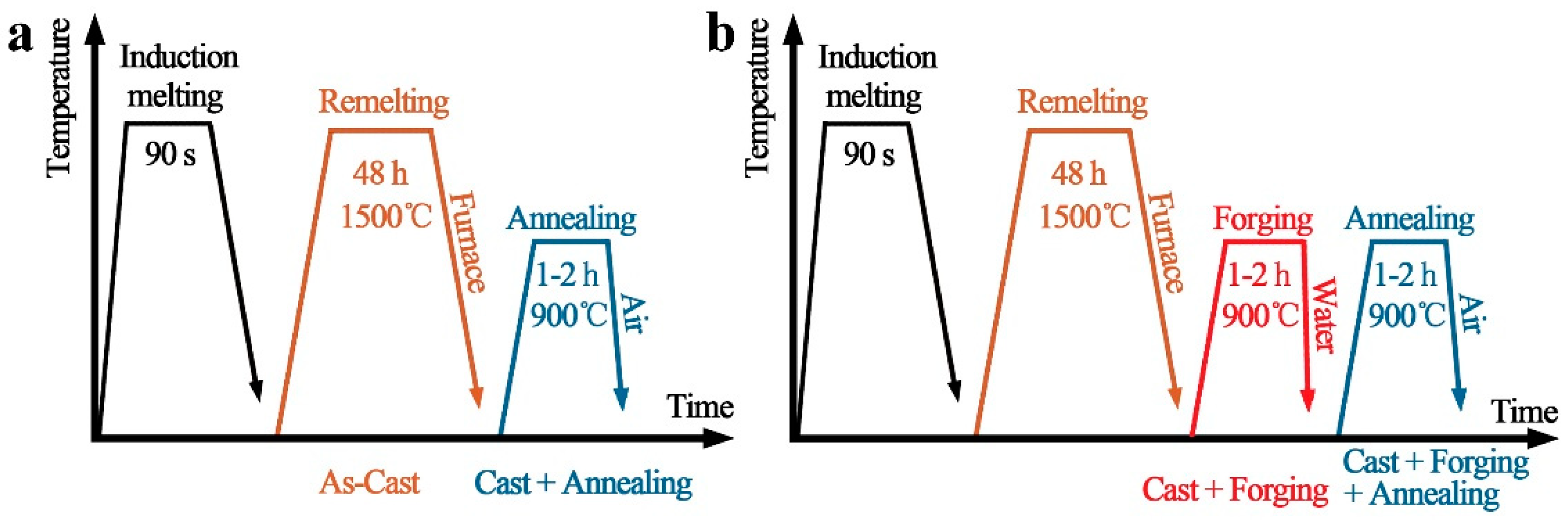
2. Materials and Methods

Fe50Mn30Co10Cr10 alloys with different carbon contents were prepared from pure metals and carbon by melting the carbon steel and casting it using a vacuum-induction melting furnace. The mass fractions of the three carbon contents were 0 wt.% (known as 0C), 0.2 wt.% (0.2C), and 0.5 wt.% (0.5C), respectively. The as-cast specimen (AC) was held at 1500 °C for 48 h in a high-purity argon atmosphere to carry out the purification treatment. The chemical compositions of the Fe50Mn30Co10Cr10 alloys systems are shown in Table 1. The dimensions of the specimens were 15 × 15 × 10 mm3. The specimens were then annealed at 900 °C for 2 h in an argon atmosphere, known as AN, and specimens were hot forged at 900 °C with a reduction of 30–40% in thickness, followed by water-cooling to room temperature, which were then called F. Subsequently, the hot forged specimens were annealed at 900 °C for 2 h in an argon atmosphere, named F-AN. A sketch of the heat treatment process of the specimens is shown in Figure 1. EDS and XRF were used to test the compositions of the specimens, and the test results were then averaged and normalized, as shown in Table 2. Specimens and corresponding treatment processes are shown in Table 3.
The microstructure of the Fe50Mn30Co10Cr10 alloy system was characterized by scanning electron microscopy (SEM). X-ray diffraction (XRD) analysis was used to analyze the phase compositions of the specimens with Cu Kα at 40 kV and 40 mA, between 35 and 105 deg (2θ). The 2θ scanning speed was 1°/min during the measurements. The specimens for optical microscopy (OM) and tensile tests were prepared using electric discharge wire-cutting. The specimens were all polished with 0.2 μm alumina polishing powder and etched with aqua regia (HNO3:HCl = 1:3), after which the surface of the specimens was cleaned with 75% ethanol solution. The tensile mechanical properties were tested on a UTM53305 universal testing machine with a displacement rate of 0.5 mm/min. The hardness of the specimens was measured using a Vickers hardness tester held at 1 kg for 10 s, and each specimen was tested 3–5 times with an average value taken to avoid errors.

3. Results and Discussion

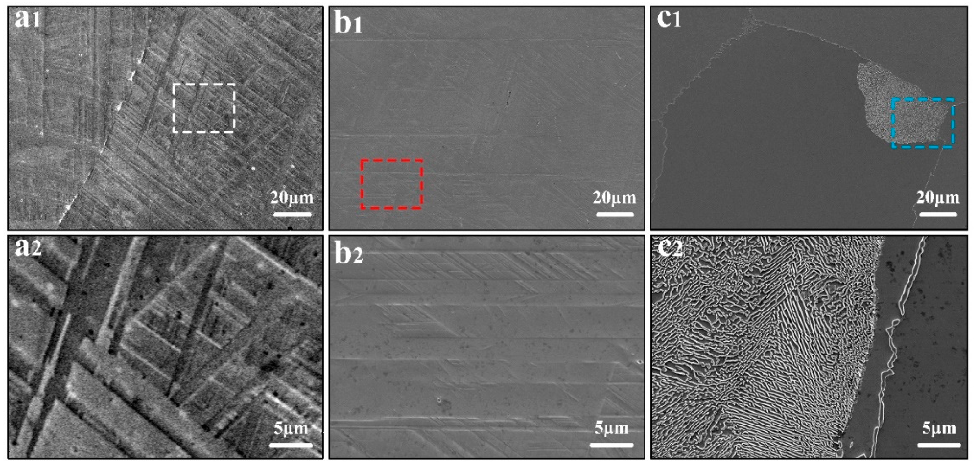
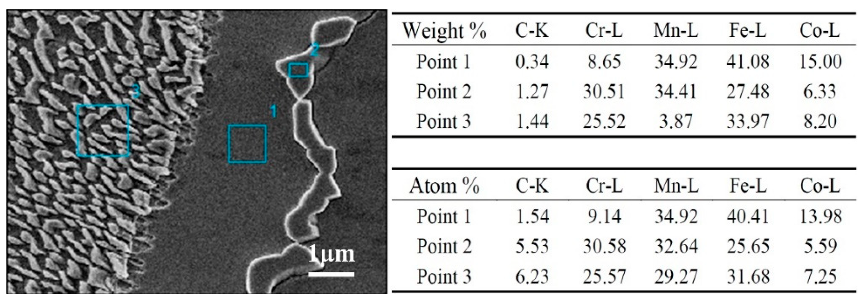
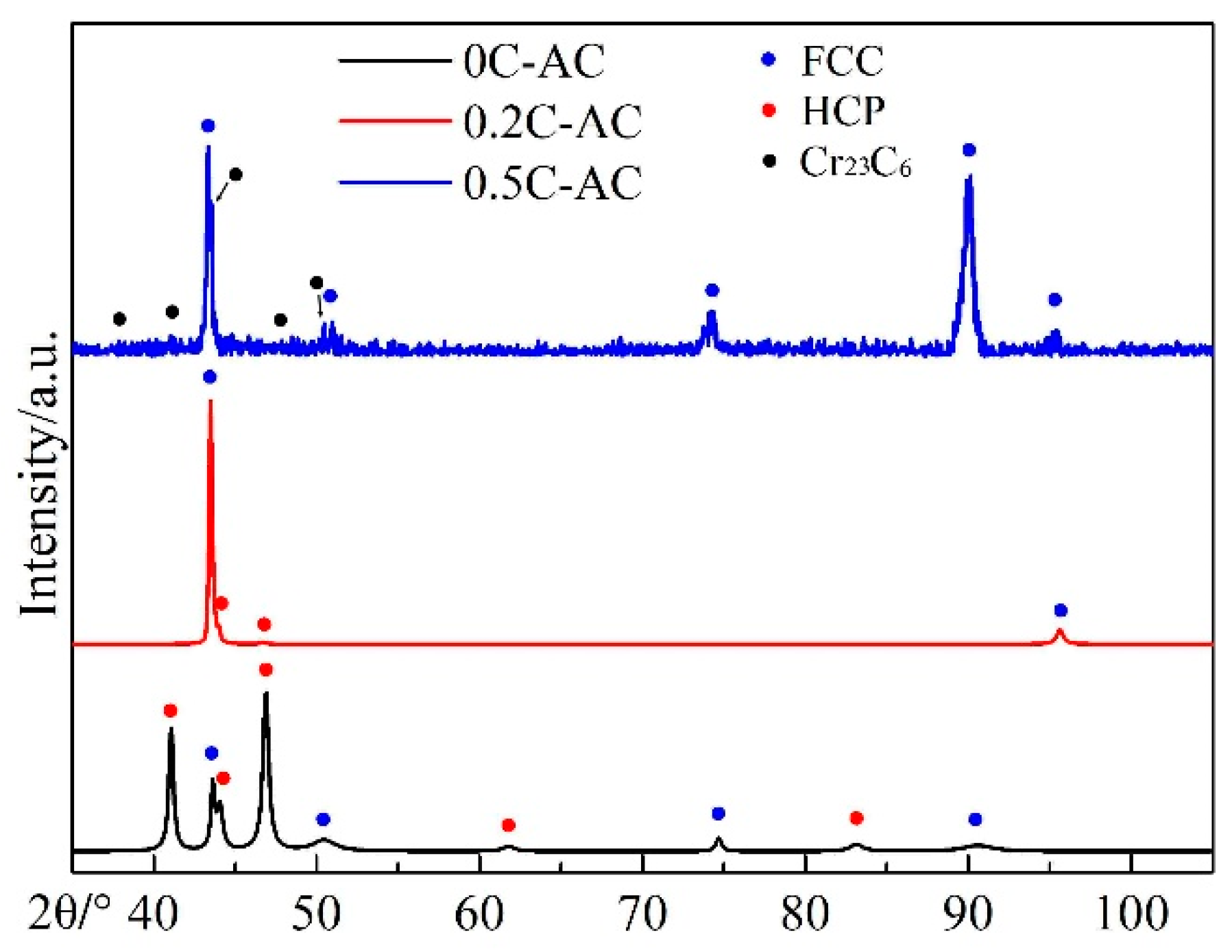
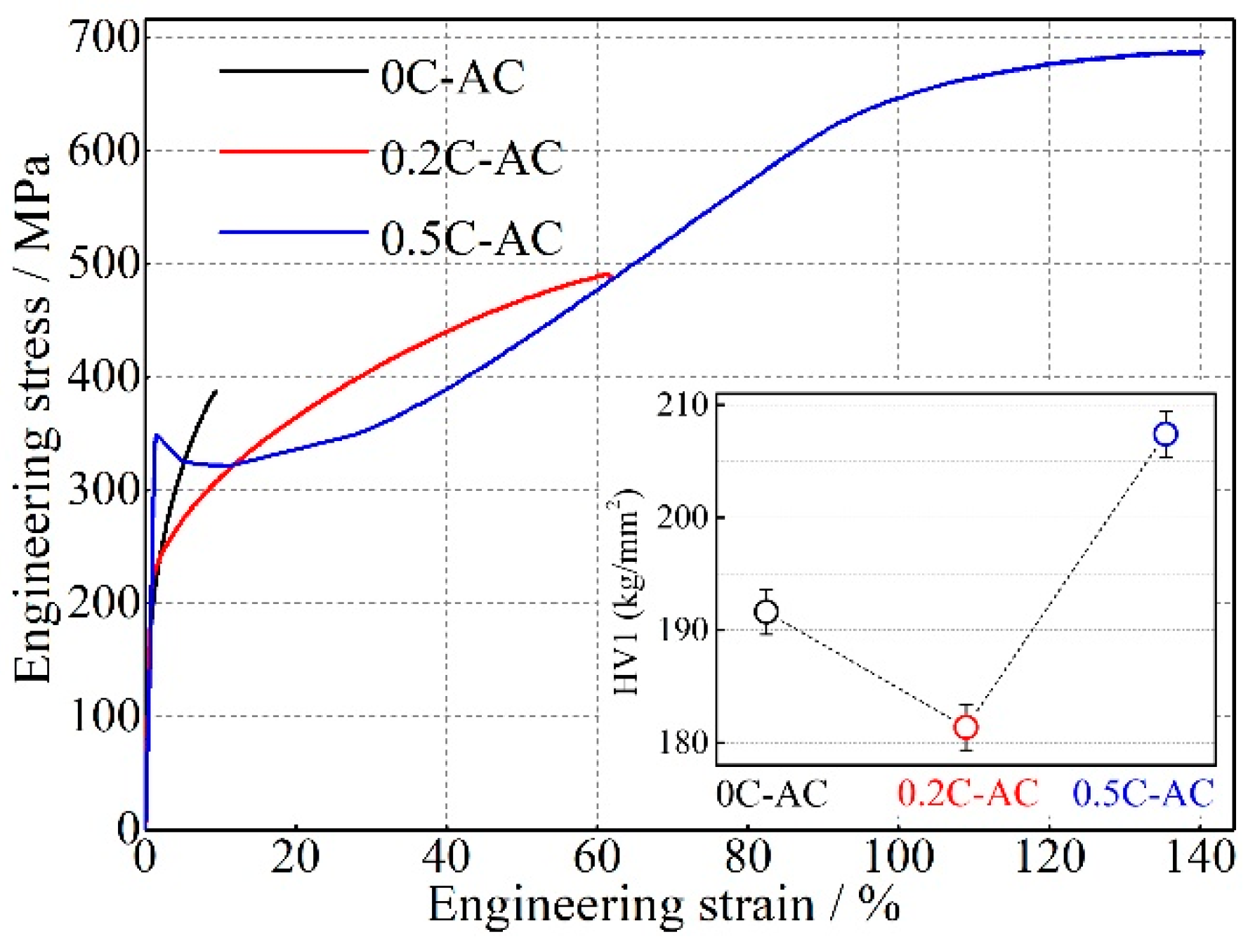
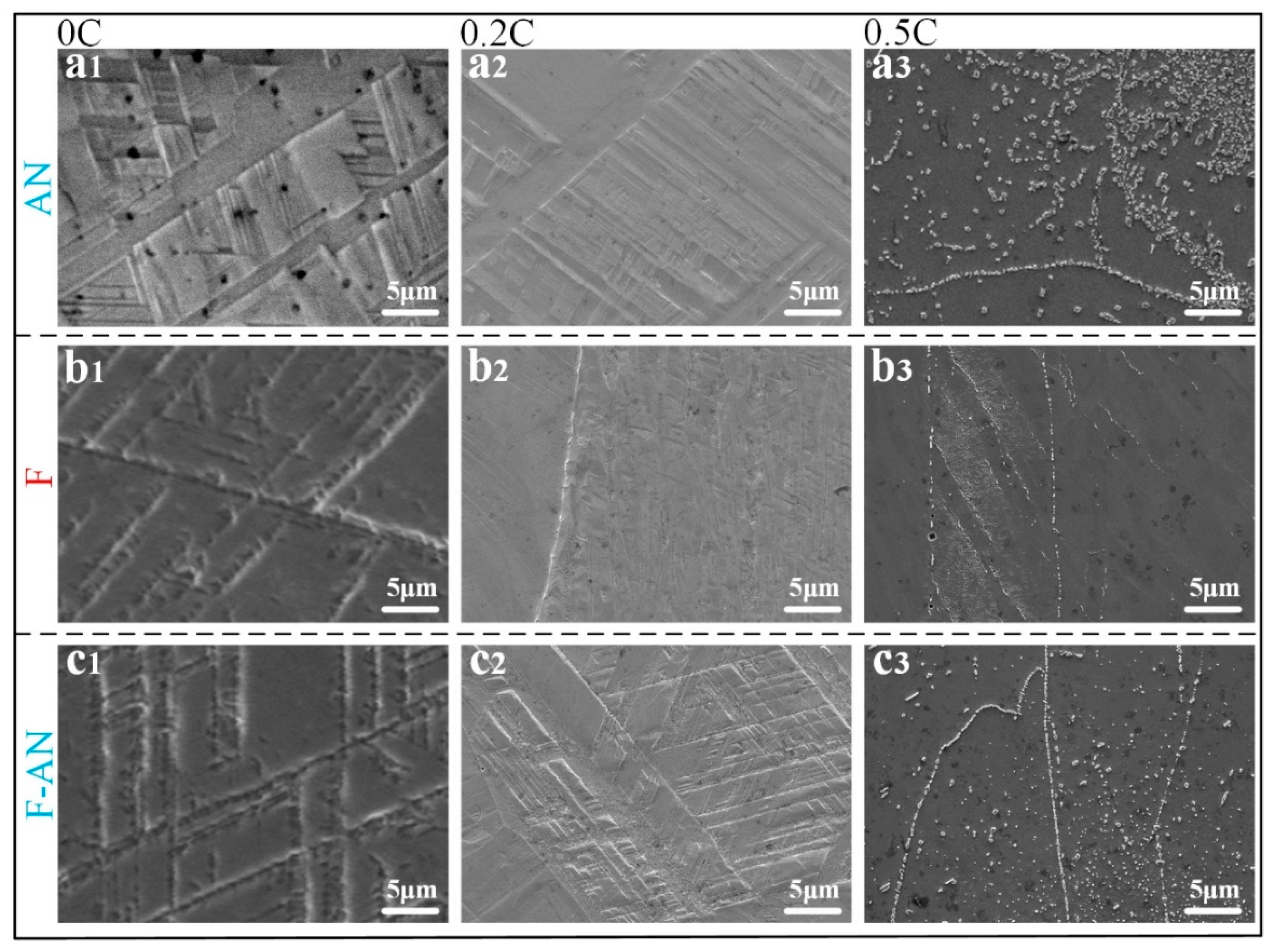
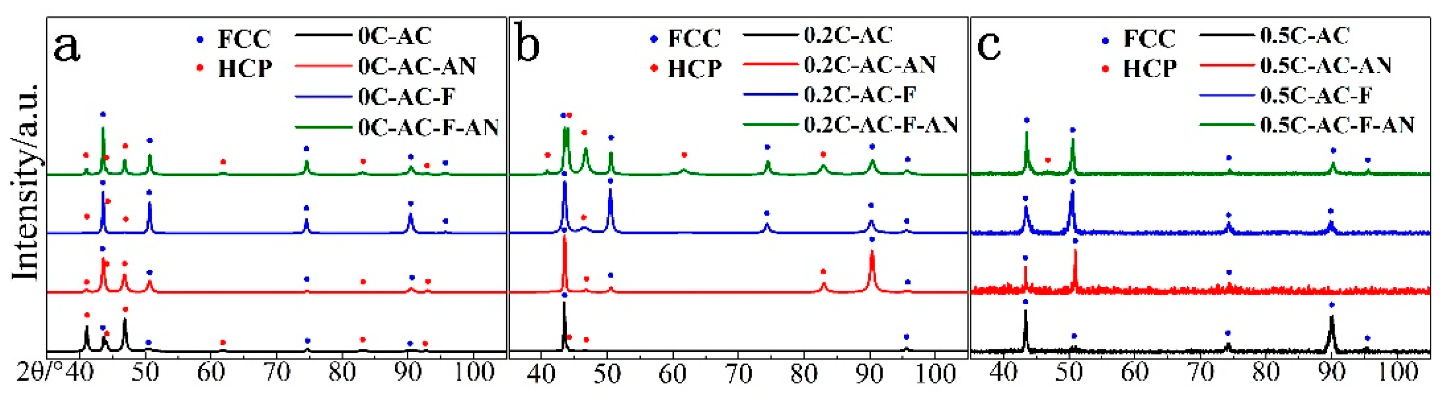
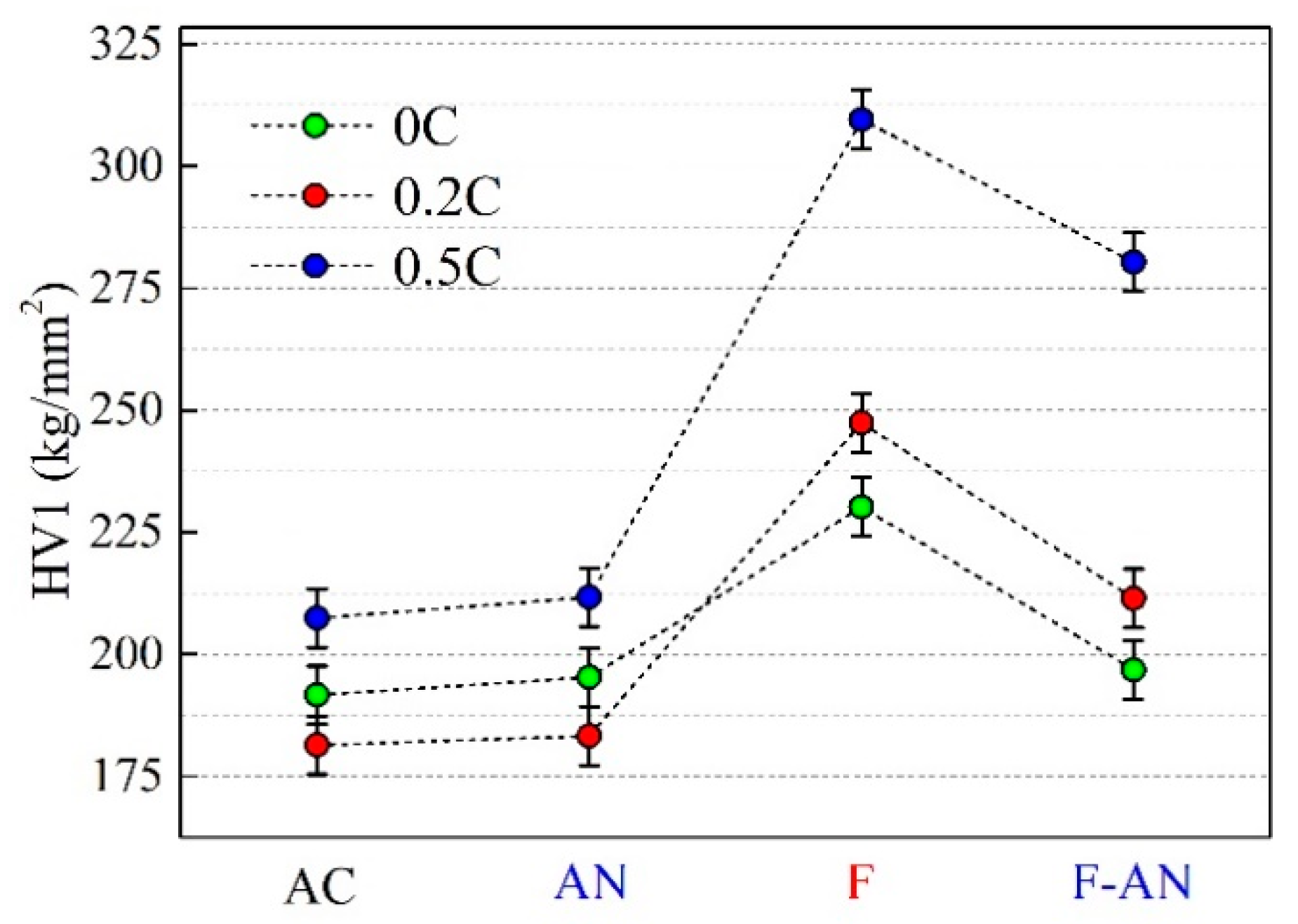
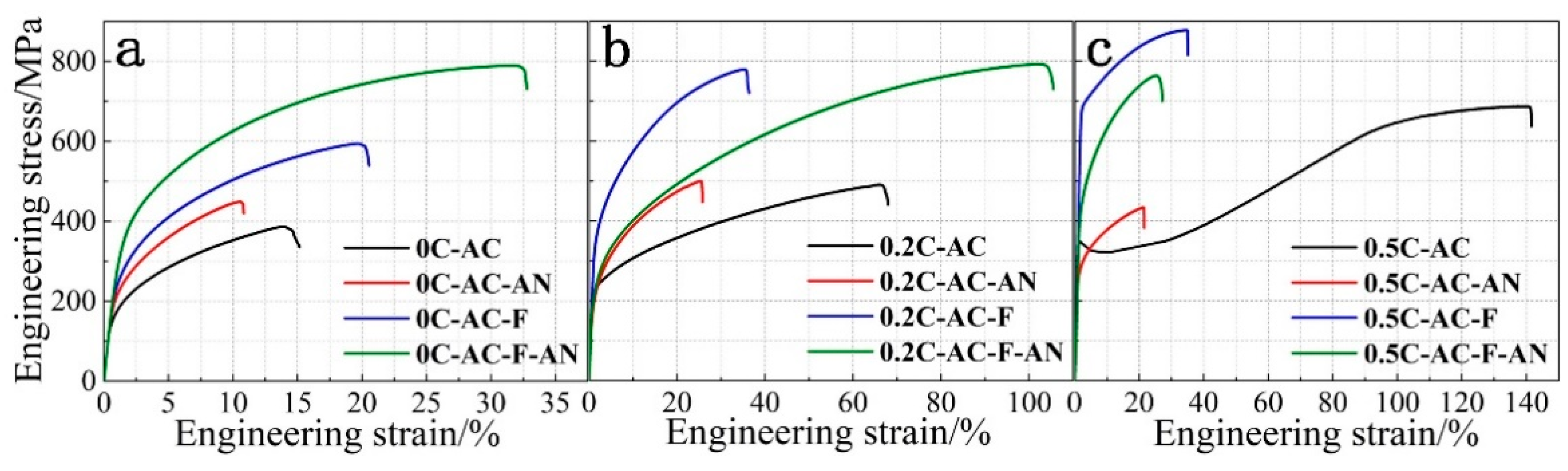
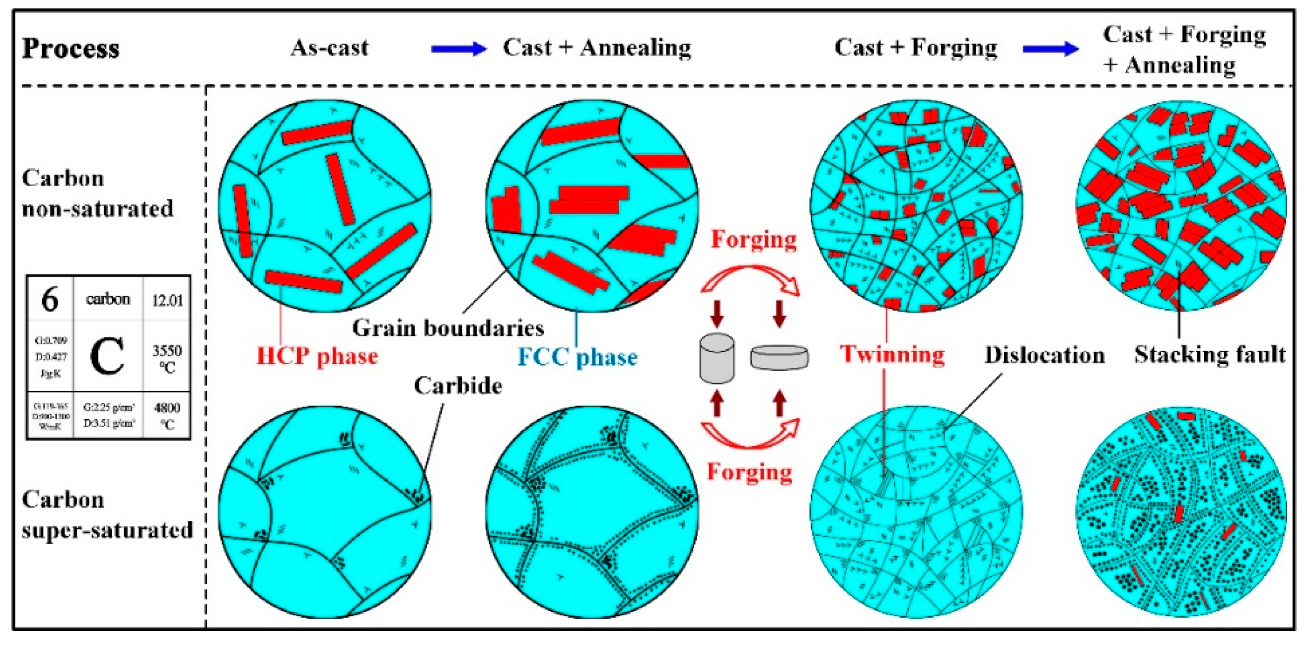
3.1. Effect of Interstitial Carbon Atoms on the Microstructure and Properties of Fe50Mn30Co10Cr10 Alloy

As shown in Figure 2, a larger amount of HCP phase emerged in specimens 0C-AC and 0.2C-AC with low carbon contents, which were distributed with different orientations. Yet companying the carbon content increased to 0.5 wt.%, a small HCP phase but densely dispersed carbides could be observed in specimen 0.5C-AC (Figure 2c1). Transition from the FCC phase to the HCP phase tends to be promoted in low carbon content Fe-Mn alloys with low stacking fault energy (SFE) [25], while the addition of interstitial carbon atoms increased the SFE, causing the stabilization of the FCC phase and inhibiting its transformation into the HCP phase [7,23,24]. Meanwhile, the carbon element has a main effect on stabilizing austenite with the FCC phase and inhibiting the generation of martensitic transformation. Hence, an evident difference exists between the HCP phase of specimens 0.2C-AC and 0.5C-AC, due to the lower SFE. Additionally, accompanying the further increase in carbon content, excess interstitial carbon atoms can precipitate as carbides in the matrix, as shown in Figure 3, and the contents of C and Cr elements in the precipitated phase is higher than that in the matrix, which may well be Cr23C6 carbides with a patch morphology [26,27]. For specimen 0.5C-AC, carbides were precipitated in two forms, namely continuous network carbides and discontinuous aggregated carbides. The former mainly distributed along grain boundaries, and the latter distributed inside the grain and near the intersection of grain boundaries. The carbides with a network distribution gave rise to a partial decrease in stability of the matrix along with a decrease in the solid solubility in the grain, while the aggregated carbides could improve the hardness.
Figure 4 shows the XRD patterns of Fe50Mn30Co10Cr10 alloys with three different carbon contents. Specimens without the addition of solute carbon atoms showed a dual-phase (DP) structure composed of FCC and HCP phases. With the increase in carbon content to 0.2 wt.%, the integral intensity of the HCP phase decreased. However, with only a slight number of interstitial carbon atoms added, the phase transition could not be completely inhibited, and thus the specimen still had two phase peaks. When the carbon content increased to 0.5 wt.%, HCP completely disappeared and the FCC matrix phase remained. Combined with the above theory, we concluded that due to the saturation of the solid solubility of interstitial carbon atoms, lattice distortion and SFE were significantly increased, and the FCC phase transition was completely suppressed, so no HCP phase remained in the FCC matrix. Furthermore, in terms of the XRD patterns for 0.5C-AC, the peaks corresponding to carbides could not be clearly observed due to the scarcity of carbides.
The inset in Figure 5 shows the hardness diagram of the Fe50Mn30Co10Cr10 alloy system with different carbon contents. Specimen 0.2C-AC had a slight decrease in hardness compared with 0C-AC, while a highest hardness was achieved by specimen 0.5C-AC. Specimens 0C-AC and 0.2C-AC both had a DP structure. The FCC phase had more slip systems among these two phases, which meant a favorable plasticity and poor hardness [27,28]. Therefore, despite having a solid solution strengthening effect, 0.2C-AC, which had more FCC phases, had a lower hardness. For 0.5C-AC, two factors evidently affected the hardness, the solid solution strengthening effect and the precipitated carbides. Thus, the hardness was improved greatly, reaching 211.7 HV.
Figure 5 shows the engineering stress–strain curve and the mechanical properties of the Fe50Mn30Co10Cr10 alloy system with different carbon contents. As shown in Figure 5, the largest yield strength of 349.4 MPa was obtained by specimen 0.5C-AC, while specimen 0.2C-AC has a lowest value of 210.3 MPa. We know that an important factor affecting the yield strength of a material is the solute element in the metal. This method of increasing strength is solid solution strengthening. In the Fe50Mn30Co10Cr10 alloy system, carbon atoms are introduced as interstitial-solution atoms. Due to the addition of carbon atoms, the original matrix lattice can be distorted and interact with the stress concentration area generated by the dislocations that pile up and form the Cottrell. When subjected to tensile stress, additional stress is required for dislocation migration, thus causing an increase in yield strength. With the increase in interstitial carbon atoms, the solid solution strengthening effect becomes more obvious.
Comparing 0C-AC and 0.2C-AC, although it has a higher solid solution strengthening effect, the greater slip systems decease the yield strength of 0.2C-AC. In terms of 0.5C-AC, a highest yield strength was obtained and originated from the greater number of interstitial carbon atoms. In the meantime, large amounts of carbides precipitated as the second phase, which introduced a favorable dispersion strengthening effect, improving the strength.
It can be clearly seen that with the increase in interstitial carbon atoms, the elongation of the alloy system increased significantly. The addition of carbon atoms weakens the phase transition ability of the FCC phase. Plasticity improved, accompanying the increase in the FCC phase. According to the study of Otto [6], the microstructure and metastable stacking fault formed by 1/6<112> partial dislocation slipping in the FCC phase could provide nucleation sites for the HCP phase. In addition, the FCC phase has more slip systems, which could greatly contribute to ductility [27]. Therefore, the fracture elongation of 0.5C-AC, with a greater FCC phase, reaches the greatest value of 141%.

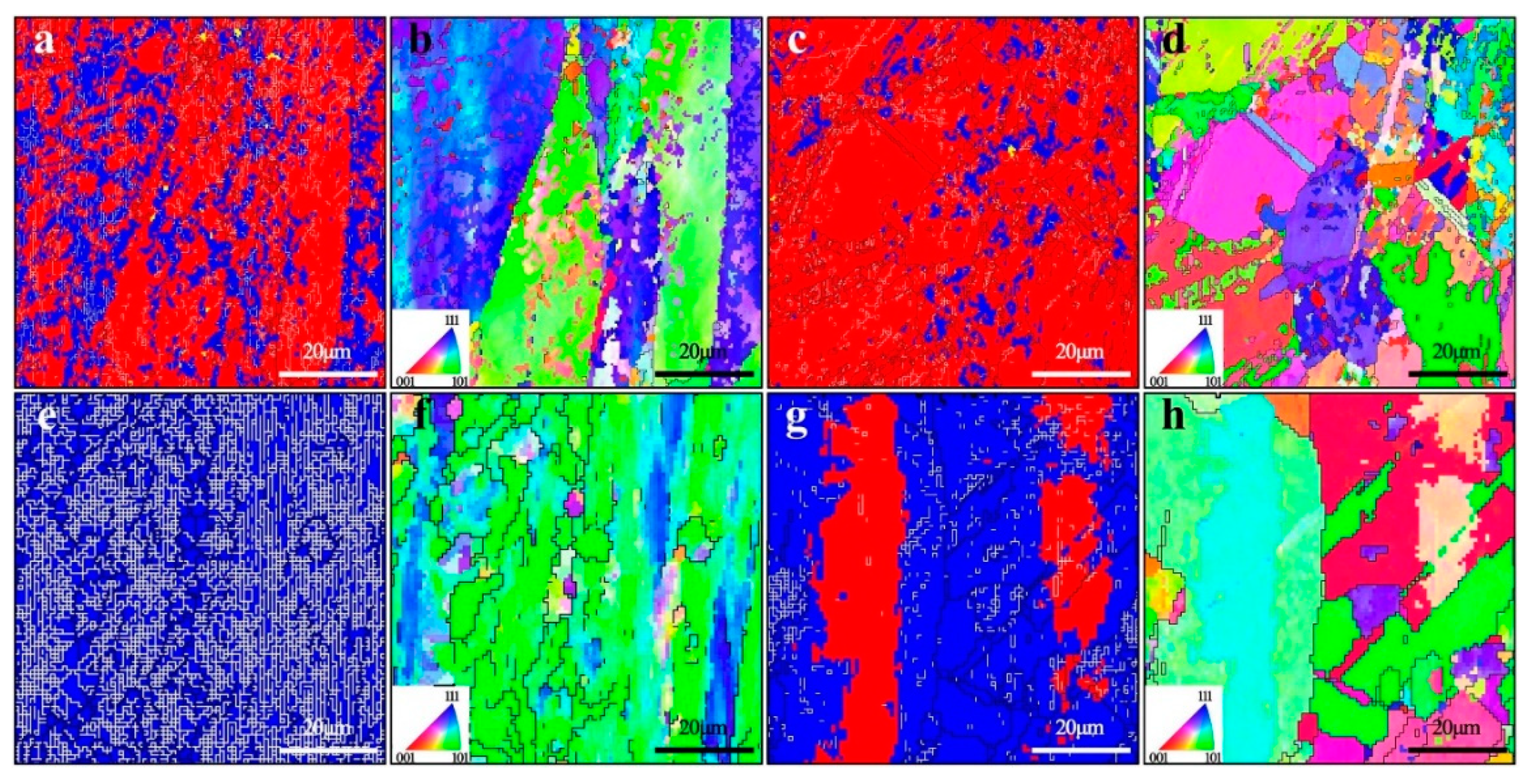
3.2. Effect of Heat Treatment on the Microstructure and Properties of Fe50Mn30Co10Cr10 Alloy

Figure 6 shows SEM images of the specimen surface of the Fe50Mn30Co10Cr10 alloy under different heat treatment states with three carbon contents. Despite being annealed, the FCC phase and the HCP phase remained in specimens 0C-AC-AN and 0.2C-AC-AN, while specimen 0.5C-AC-AN mainly comprised an FCC phase and precipitated carbides, which were concentrated at the grain boundary with a small number of carbides distributed inside the grain. After hot forging, the surface morphology of the specimens changed significantly, and the large blocky HCP phase increased in number but were smaller in specimens 0C-AC-F and 0.2C-AC-F. In terms of 0.5C-AC-F, the number of carbides greatly reduced, mainly distributing at the intersection of the grain boundaries. Specimens 0C-AC-F-AN and 0.2C-AC-F-AN had a large increase in HCP phase. The 0.5C-AC-F-AN has more carbide than 0.5C-AC-F, concentrated at the grain boundaries.
As for specimen 0.5C-AC-AN, a large amount of carbon atoms diffused and segregated to the grain boundaries, as a result of high temperature annealing, around which quite a few carbides precipitated [27,29]. Hot forging broke the bulk grains, inducing a large number of stacking faults (SFs) and inhibiting phase transition, due to which the HCP phase became finer and there were fewer cases. After annealing twice, large amounts of dislocations, produced by hot forging, were rearranged and offset due to the high temperature. Hence the stability of the FCC phase decreased, and more HCP phases could be observed in 0C-AC-F-AN and 0.2C-AC-F-AN. In terms of 0.5C-AC-F-AN, large amounts of solid-solute carbon atoms in the matrix precipitated after annealing at a high temperature.
Figure 7 shows the XRD patterns of the four states with different carbon contents. The diffraction patterns of the specimens of three kinds of carbon content did not change significantly after annealing. For 0C-AC-F and 0C-AC-F-AN, the HCP phase diffraction peaks of the specimens after hot forging were greatly reduced, and increased after annealing again. In terms of the specimens with a carbon content of 0.2 wt.%, the volume fraction of the HCP phase increased from 9.73% as-cast to 14.77% after hot forging, as obtained by X-ray diffraction analysis. However, in terms of 0.5C-AC-F-AN, the peak of the HCP phase appeared for the first time.
The HCP phase of the annealed specimens increased greatly, due to the segregation of carbon atoms during the high-temperature process. The carbon concentration in the matrix decreased, and there was not enough SFE to inhibit the generation of phase transitions. The hot forging process generated a large amount of SFE and dislocations, while during the annealing process after hot forging, the diffusion of atoms and the dislocation migrations, redisplaying, and recombining occurred. The metastable stacking dislocation caused by a partial dislocation slip moved in the direction of low energy, which enabled the HCP phase to nucleate and grow. Hence, the HCP phase was greatly improved. The electron backscatter diffraction (EBSD) phase diagrams in Figure 8 visually show that the phase volume fractions (the red areas represent the HCP phase and the blue areas represent the FCC phase) of the two interstitial carbon atom concentration alloys and the hot forged specimens have a large number of small-angle grain boundaries (white lines) due to external forces. It is worth noting that specimens with a carbon content of 0.5 wt.% obtained the HCP phase after annealing treatment after hot forging. This is because the 0.5 wt.% carbon content in the initial as-cast specimen reached saturation. As for specimen 0.2C-AC-F-AN, annealing twins appeared after annealing, which may well have produced the TWIP effect during deformation. As shown in Figure 8a,e, it can be observed that both the high-angle grain boundaries and the low-angle grain boundaries were dense and fine. After annealing, hot forging with high loading notably refines the grains, as shown in Figure 8c,g. Comparing the EBSD diagrams of specimens after annealing, hot forging with a high load destroyed and refined the grains. After annealing, with a large-scale precipitation of carbides, the amount of solid-solution carbon atoms dropped below the concentration limit. Subsequently, the concentration of the solid-solution carbon atoms could no longer stabilize the FCC phase, so the HCP phase appeared.
Figure 9 shows the hardness of the Fe50Mn30Co10Cr10 alloy after different heat treatments. The hardness evolution of the three carbon-containing specimens after different heat treatments was almost the same. The hardness of the specimen after hot forging was the lowest, and the hardness of the as-cast and annealed specimens was almost the same. After hot forging, the hardness of the annealed specimens dropped significantly, but were still higher than that of the as-cast specimens. After hot forging, large amounts of dislocations were generated, and grains were broken at the same time, so that the grains were refined, inducing grain refinement strengthening; as such, 0.5C-AC-F obtained the greatest hardness. After annealing, most of the dislocations with different signs were offset from each other, and the hardness was slightly reduced due to the influence of recovery and recrystallization.
From the perspective of the yield strength of the alloy, it can be seen in Figure 10 that the yield strength of the as-cast alloy system with 0.2 wt.% carbon content decreased slightly after being annealed, and the yield strength of the hot-forged specimen was the highest, the yield strength of the specimen decreased after further annealing. A positive correspondence could be found between the yield strength alteration with the fraction evolution of the FCC phase in the specimens. In addition, in terms of the strengthening mechanism, solid-solution strengthening played a critical role in the as-cast specimens. As the interstitial carbon atoms diffused after annealing, the solid-solution strengthening effect was weakened. After hot forging, combined with solid-solution strengthening, grain refinement strengthening was introduced and a large quantity of dislocations was generated; as such, a highest yield strength was achieved. After annealing, partial dislocations and stacking faults were eliminated, and the yield strength decreased accordingly. Figure 10c shows that the yield strength of 0.5 C-AC-F-AN showed the same trend as that of 0.2C-AC-F-AN. However, since this specimen only had an FCC single phase, it can be explained by the theory of strengthening mechanisms, as mentioned above.
As for the elongation, a great many dislocations disappeared in the annealed specimens, and strain hardening was reduced, so the elongation of the annealed specimens decreased. In terms of specimen 0.5C-AC-AN, the carbon atoms precipitated to form hard carbide particles. When deformation occurred, these hard phases reduced the elongation of the specimen. Similarly, a large number of carbides precipitated after hot forging, but a great many dislocations and mechanical twins were produced, inducing the TWIP effect. The integrated intensity of the HCP phase was also quantitatively analyzed relative to the XRD test results. Comparing the specimens with two carbon contents, 0.2 wt.% and 0.5 wt.%, both forging and annealing at a low carbon content increased the HCP phase, and the TRIP effect played an important role. A high carbon content, except for 0.5C-AC-F-AN, FCC acts as the single phase, and the TWIP effects were mainly plastic enhancement mechanisms. The TRIP effect occurs only after the appearance of the HCP phase. As carbon content increases, the TWIP effect plays a greater role and the TRIP effect decreases slightly [30]. However, dislocations gradually disappeared, and carbides precipitated during annealing after hot forging, causing a decrease in elongation.

3.3. Fe50Mn30Co10Cr10 Alloy Strengthening and Toughening Mechanism

Combined with the microstructure and mechanical properties of Fe50Mn30Co10Cr10 alloy, the dual-phase structure and strengthening and toughening mechanisms of specimens with different carbon contents were analyzed and summarized. Figure 11 shows a schematic diagram of the strengthening–toughening mechanism of specimens with different carbon contents under different heat treatment states. As the solid solubility of interstitial carbon atoms increases, the degree of lattice distortion increases, which leads to an increase in stacking fault energy and the inhibition for the transformation from γ (FCC) to ε (HCP) [31]. With the increase in the carbon element, the FCC phase is stabilized. For 0.5 wt.% alloy, the interstitial carbon atoms reached the limit of solid solubility, and the excess carbon atoms precipitated to form carbides, which obtained a combination phase of FCC and carbide. Single-phase FCC structures, during the entire tensile procedure, showed changes in the deformation mechanism from dislocation slip to twinning under higher strains.
The alloys that did not reach the limit of solid solubility had a dual-phase structure of FCC and HCP. Due to the solid solution of some carbon atoms, a lattice distortion is induced, resulting in solid solution strengthening, which significantly improves the yield strength of the alloy. The matrix FCC phase was stabilized due to the solid solution of the interstitial carbon atoms. After annealing, accompanying the precipitation of partial carbon atoms, the degree of lattice distortions was reduced and dislocations and stacking faults were mutually offset, with the FCC phase transformed into the HCP phase, and the yield strength and elongation decreased [32]. After hot forging, phase transformation and large amounts of mechanical twins were generated and the grains were refined. In favor of the TRIP–TWIP-coupled effect [5,31,33,34] and grain refinement strengthening, the annealed specimens obtained a higher yield strength and elongation. During subsequent annealing, accompanying the formation of annealing twins, the FCC phase continued to transform, with the TRIP–TWIP coupled effect being exerted [35,36,37,38].
To explore the relationship between the strengthening mechanism and the microstructure evolution of the alloy in different states, quantitative calculations were implemented for the strengthening approaches, including solid-solution strengthening, grain refinement strengthening, and precipitation strengthening, as discussed in what follows. Since the carbon content was the main variable in the present work, here, we only take the strengthening effect of solid-solute carbon atoms into consideration.
σ s s = K γ C γ
where σ s s represents the strengthening effect caused due to solid solution, K γ is the factor of the modulus corresponding to the carbon element, of which the value is equal to 187 MPa·(wt.%)−1 [39,40], and C γ is the mass fraction of carbon. In comparison with the specimens with no added carbon, the specimens with a carbon content of 0.2 wt.% had a contribution of 37.4 MPa to strength, and the specimens containing 0.5 wt.% carbon generated a larger devotion of 93.5 MPa, which indicated that the solid-solution strengthening effect of carbon played a great role in the overall strengthening mechanism.
The grain sizes of specimens 0.2C-AC-F and 0.2C-AC-F-AN were quantitatively analyzed, and the average sizes were 0.4584 μm and 0.6542 μm, respectively. The effect of grain size on strength was quantified using the Hall–Petch relationship.
σ g b = σ 0 + K y D 0.5
Here, σ g b represents strengthening due to grain boundaries, σ 0 is the friction stress of pure iron, K y is gain size strengthening factor, and D is average grain size. The value K y = 370 MPa μm1/2 was taken here [41]. The results show that strengthening due to grain boundaries after hot forging was 89.17 Mpa higher than that after hot forging and annealing. This indicated that fine grains bring about a higher strength.
Precipitation strengthening also plays an important role in alloys with carbon contents of 0.5 wt.%. The Orowan mechanism [42] was introduced to quantify the strengthening effect of precipitation.
σ p = 0.538 G b D p f p 1 / 2 ln D p 2 b
where σ p represents strengthening due to second phase precipitates. G is the shear modulus (MPa), b is the Burgers vector (mm), f p is the volume fraction of particles, and D p is the diameter of the particles (mm). Precipitation strengthening analyses were carried out for different heat treatment states of specimens with a carbon content of 0.5 wt.%, the volume fraction of the carbides in the as-cast specimen was only 1%, and evolved into 4.3% and 2.4% after annealing and hot forging, respectively. The content of the precipitated carbides in the specimen annealed after hot forging peaked at 7.9%. According to the Orowan mechanism, precipitation strengthening s was calculated to be 26.7, 175.3, 130.9, and 237.6 MPa, respectively. The contribution of the precipitation strengthening effect increased with the increase in precipitated carbides.
In the Fe50Mn30Co10Cr10 alloy system, after the interstitial carbon atom content reached the solid solubility limit, the phase transition of the FCC phase is suppressed due to the high stacking faults, and the excessive carbon precipitate carbides and is distributed in the FCC matrix, which acts as a hard phase to provide the effect of dispersion and strengthening. With hot forging and annealing, the grain refinement and carbide gradually precipitate, the concentration of carbon atoms in the matrix decreases below the saturation point, the stability of the FCC phase decreases, and it begins to change into an HCP phase. Due to there being too many interstitial carbon atoms, although the precipitated carbides have a greater increase in the yield strength of the alloy, they also severely weaken plastic properties.
In comparison, specimen 0.2C-AC-F-AN obtained the best comprehensive mechanical properties, in which a favorable phase distribution was generated. High strength was provided by the HCP phase, while a good plasticity was achieved from the TWIP effect of the FCC phase induced under a large strain. Moreover, a probable carbon content provided the FCC phase with favorable stability, due to which a better TRIP effect was induced. Additionally, a slight quantity of dislocations and stacking faults maintained the yield strength after the forging with subsequent annealing process. In other words, the TRIP–TWIP effect contributed significantly to the strength and plasticity.

4. Conclusions

In this work, we systematically investigated the effects of variable interstitial carbon atoms and different heat treatment processes on the deformation behavior of Fe50Mn30Co10Cr10 alloy systems. The main conclusions are:
(1) The Fe50Mn30Co10Cr10 alloy is an FCC+HCP dual-phase structure, when the carbon content below 0.2 wt.%. In the alloy with a carbon content of 0.5 wt.%, large amounts of interstitial carbon atoms are solidly dissolved in the matrix and cause lattice distortion, the metastable FCC phase is stabilized and the phase transition is inhibited. Excess carbon atoms precipitate as carbides, and a multi-phase of the FCC and carbide are obtained.
(2) Due to the DP structure, the Fe50Mn30Co10Cr10 system alloy will undergo stress-induced phase transformation due to the applied load during the uniaxial stretching process, triggering the TRIP effect. Twinning occurs in the later stage of deformation, and the TWIP effect occurs. Plasticity is improved with the synergistic effects of TRIP and TWIP. The addition of interstitial carbon atoms has the effect of solid-solution strengthening, and an appropriate amount of carbon can stabilize the DP structure, which can better exert the TRIP and TWIP effects, so that as the carbon content increases and the yield strength, tensile strength, and elongation of the dual-phase alloy in the as-cast state are all obviously higher. In alloys with added interstitial carbon, especially the 0.5 wt.% Fe50Mn30Co10Cr10 alloy, carbides would precipitate during hot forging and annealing, which can increase the hardness and yield strength, but decrease the plasticity.
(3) The cyclic transformation of the FCC phase and the HCP phase is achieved by adding interstitial carbon atoms and using different heat treatments. The alloy continues to undergo phase transformation and twinning-induced plasticity under stress due to deformation behavior. Through different strengthening effects, the yield strength of the alloy is improved. Phase transformation, twins, and dislocations increase the plasticity during deformation process.

Author Contributions

Conceptualization, J.W. and Q.T.; data curation, Z.P., T.L., T.Z., J.W. and Q.T.; formal analysis, Q.T.; funding acquisition, Q.T.; investigation, L.W., J.L., J.W. and Q.T.; methodology, J.W.; resources, Q.T.; software, Z.P.; supervision, Q.T.; visualization, T.Z.; writing—original draft, Z.P.; writing—review and editing, J.W. and Q.T. All authors have read and agreed to the published version of the manuscript.

Funding

This work was financially supported by the National Natural Science Foundation of China (Grant Nos. 51805533, 51641109).

Institutional Review Board Statement

Not applicable.

Informed Consent Statement

Not applicable.

Data Availability Statement

The data presented in this study are available on request from the corresponding author.

Conflicts of Interest

The authors declare no conflict of interest.

References

  1. Watanabe, K.; Kawasaki, T.; Tanaka, H. Structural origin of enhanced slow dynamics near a wall in glass-forming systems. Nat. Mater. 2011, 10, 512–520. [Google Scholar] [CrossRef] [PubMed]
  2. Wei, Y.; Li, Y.; Zhu, L.; Liu, Y.; Lei, X.; Wang, G.; Wu, Y.; Mi, Z.; Liu, J.; Wang, H.; et al. Evading the strength-ductility trade-off dilemma in steel through gradient hierarchical nanotwins. Nat. Commun. 2014, 5, 3580. [Google Scholar] [CrossRef] [PubMed] [Green Version]
  3. Hadfield’s Manganese Steel. Science 1888, 12, 284–286.
  4. Bouaziz, O.; Allain, S.; Scott, C.P.; Cugy, P.; Barbier, D. High manganese austenitic twinning induced plasticity steels: A review of the microstructure properties relationships. Curr. Opin. Solid State Mater. Sci. 2011, 15, 141–168. [Google Scholar] [CrossRef]
  5. GräSsel, O.; Krüger, L.; Frommeyer, G.; Meyer, L.W. High strength Fe-Mn-(Al,Si) TRIP/TWIP steels development—properties—application. Int. J. Plast. 2000, 16, 1391–1409. [Google Scholar] [CrossRef]
  6. Otto, F.; Dlouhý, A.; Somsen, C.; Bei, H.; Eggeler, G.; George, E.P. The influences of temperature and microstructure on the tensile properties of a CoCrFeMnNi high-entropy alloy. Acta Mater. 2013, 61, 5743–5755. [Google Scholar] [CrossRef] [Green Version]
  7. Saeed-Akbari, A.; Imlau, J.; Prahl, U.; Bleck, W. Derivation and Variation in Composition-Dependent Stacking Fault Energy Maps Based on Subregular Solution Model in High-Manganese Steels. Metall. Mater. Trans. A 2009, 40, 3076–3090. [Google Scholar] [CrossRef]
  8. Bastidas, D.M.; Ress, J.; Bosch, J.; Martin, U. Corrosion Mechanisms of High-Mn Twinning-Induced Plasticity (TWIP) Steels: A Critical Review. Metals 2021, 11, 287. [Google Scholar] [CrossRef]
  9. Haase, C.; Barrales-Mora, L.A. From High-Manganese Steels to Advanced High-Entropy Alloys. Metals 2019, 9, 726. [Google Scholar] [CrossRef] [Green Version]
  10. Troiano, A.R.; Mcguire, F.T. A study of the iron-rich iron-manganese alloys. Presented at the 24th Annual Convention of the American Society for Metals, Cleveland, OH, USA, 12–16 October 1942. [Google Scholar]
  11. Li, D.; Feng, Y.; Song, S.; Liu, Q.; Bai, Q.; Ren, F.; Shangguan, F. Influences of silicon on the work hardening behavior and hot deformation behavior of Fe–25 wt%Mn–(Si, Al) TWIP steel. J. Alloy Compd. 2015, 618, 768–775. [Google Scholar] [CrossRef]
  12. Li, Z.; Pradeep, K.G.; Deng, Y.; Raabe, D.; Tasan, C.C. Metastable high-entropy dual-phase alloys overcome the strength-ductility trade-off. Nature 2016, 534, 227–230. [Google Scholar] [CrossRef] [PubMed]
  13. Li, Z.; Raabe, D. Strong and Ductile Non-equiatomic High-Entropy Alloys: Design, Processing, Microstructure, and Mechanical Properties. JOM 2017, 69, 2099–2106. [Google Scholar] [CrossRef] [PubMed]
  14. Cantor, B.; Chang, I.T.H.; Knight, P.; Vincent, A.J.B. Microstructural development in equiatomic multicomponent alloys. Mater. Sci. Eng. A 2004, 375–377, 213–218. [Google Scholar] [CrossRef]
  15. Stepanov, N.D.; Yurchenko, N.Y.; Tikhonovsky, M.A.; Salishchev, G.A. Effect of carbon content and annealing on structure and hardness of the CoCrFeNiMn-based high entropy alloys. J. Alloy. Compd. 2016, 687, 59–71. [Google Scholar] [CrossRef]
  16. Li, Z.; Zhao, S.; Alotaibi, S.M.; Liu, Y.; Wang, B.; Meyers, M.A. Adiabatic shear localization in the CrMnFeCoNi high-entropy alloy. Acta Mater. 2018, 151, 424–431. [Google Scholar] [CrossRef] [Green Version]
  17. Yang, S.; Yang, Y. Thermodynamics-kinetics of twinning/martensitic transformation in Fe50Mn30Co10Cr10 high-entropy alloy during adiabatic shearing. Scr. Mater. 2020, 181, 115–120. [Google Scholar] [CrossRef]
  18. Li, Z.; Tasan, C.C.; Pradeep, K.G.; Raabe, D. A TRIP-assisted dual-phase high-entropy alloy: Grain size and phase fraction effects on deformation behavior. Acta Mater. 2017, 131, 323–335. [Google Scholar] [CrossRef]
  19. Tang, Z.Y.; Misra, R.D.K.; Ma, M.; Zan, N.; Wu, Z.Q.; Ding, H. Deformation twinning and martensitic transformation and dynamic mechanical properties in Fe–0.07C–23Mn–3.1Si–2.8Al TRIP/TWIP steel. Mater. Sci. Eng. A 2015, 624, 186–192. [Google Scholar] [CrossRef]
  20. Li, K.; Yu, B.; Misra, R.D.K.; Han, G.; Tsai, Y.T.; Shao, C.W.; Shang, C.J.; Yang, J.R.; Zhang, Z.F. Strain rate dependence on the evolution of microstructure and deformation mechanism during nanoscale deformation in low carbon-high Mn TWIP steel. Mater. Sci. Eng. A 2019, 742, 116–123. [Google Scholar] [CrossRef]
  21. Yan, K.; Bhattacharyya, D.; Lian, Q.; Kabra, S.; Kawasaki, M.; Carr, D.G.; Callaghan, M.D.; Avdeev, M.; Li, H.; Wang, Y.; et al. Martensitic Phase Transformation and Deformation Behavior of Fe-Mn-C-Al Twinning-Induced Plasticity Steel during High-Pressure Torsion. Adv. Eng. Mater. 2014, 16, 927–932. [Google Scholar] [CrossRef]
  22. Yang, G.; Kim, J.-K. An Overview of High Yield Strength Twinning-Induced Plasticity Steels. Metals 2021, 11, 124. [Google Scholar] [CrossRef]
  23. Li, Z.; Tasan, C.C.; Springer, H.; Gault, B.; Raabe, D. Interstitial atoms enable joint twinning and transformation induced plasticity in strong and ductile high-entropy alloys. Sci. Rep. 2017, 7, 40704. [Google Scholar] [CrossRef] [PubMed]
  24. Li, Z. Interstitial equiatomic CoCrFeMnNi high-entropy alloys: Carbon content, microstructure, and compositional homogeneity effects on deformation behavior. Acta Mater. 2019, 164, 400–412. [Google Scholar] [CrossRef]
  25. Sato, K.; Ichinose, M.; Hirotsu, Y.; Inoue, Y.J.I.I. Effects of Deformation Induced Phase Transformation and Twinning on the Mechanical Properties of Austenitic Fe–Mn–Al Alloys. ISIJ Int. 2007, 52, 868–877. [Google Scholar] [CrossRef]
  26. Barbé, E.; Fu, C.-C.; Sauzay, M. Fracture of coherent interfaces between an fcc metal matrix and the Cr23C6 carbide precipitate from first principles. Phys. Rev. Mater. 2018, 2, 023605. [Google Scholar] [CrossRef]
  27. Ko, J.Y.; Hong, S.I. Microstructural evolution and mechanical performance of carbon-containing CoCrFeMnNi-C high entropy alloys. J. Alloy. Compd. 2018, 743, 115–125. [Google Scholar] [CrossRef]
  28. Tsau, C.H.; Hsiao, R.W.; Chien, T.Y. Corrosion Behavior of CoCrFeNiTax Alloys in 1 M Sodium Chloride Aqueous Solution. Materials 2020, 13, 5157. [Google Scholar] [CrossRef] [PubMed]
  29. Liu, S.; Zhou, Y.; Xing, X.; Wang, J.; Yang, Y.; Yang, Q. Agglomeration model of (Fe,Cr)7C3 carbide in hypereutectic Fe-Cr-C alloy. Mater. Lett. 2016, 183, 272–276. [Google Scholar] [CrossRef]
  30. De Cooman, B.C.; Estrin, Y.; Kim, S.K. Twinning-induced plasticity (TWIP) steels. Acta Mater. 2018, 142, 283–362. [Google Scholar] [CrossRef]
  31. Grässel, O.; Frommeyer, G.; Derder, C.; Hofmann, H. Phase Transformations and Mechanical Properties of Fe-Mn-Si-Al TRIP-Steels. J. Phys. Arch. 1997, 7, 383–388. [Google Scholar] [CrossRef] [Green Version]
  32. Ahmed, J.; Daly, M. Yield strength insensitivity in a dual-phase high entropy alloy after prolonged high temperature annealing. Mater. Sci. Eng. A 2021, 820. [Google Scholar] [CrossRef]
  33. Wu, X.; Mayweg, D.; Ponge, D.; Li, Z. Microstructure and deformation behavior of two TWIP/TRIP high entropy alloys upon grain refinement. Mater. Sci. Eng. A 2021, 802. [Google Scholar] [CrossRef]
  34. Palma- Elvira, E.D.; Garnica-Gonzalez, P.; Pacheco-Cedeño, J.S.; Cruz Rivera, J.J.; Ramos-Azpeitia, M.; Garay-Reyes, C.G.; Hernández-Rivera, J.L. Microstructural development and mechanical properties during hot rolling and annealing of an automotive steel combining TRIP/TWIP effects. J. Alloy. Compd. 2019, 798, 45–52. [Google Scholar] [CrossRef]
  35. Yang, F.; Dong, L.; Hu, X.; Zhou, X.; Fang, F.; Xie, Z.; Jiang, J. Microstructural features and tensile behaviors of a novel FeMnCoCr high entropy alloys. Mater. Lett. 2020, 275. [Google Scholar] [CrossRef]
  36. He, Z.F.; Jia, N.; Ma, D.; Yan, H.L.; Li, Z.M.; Raabe, D. Joint contribution of transformation and twinning to the high strength-ductility combination of a FeMnCoCr high entropy alloy at cryogenic temperatures. Mater. Sci. Eng. A 2019, 759, 437–447. [Google Scholar] [CrossRef]
  37. Dong, Y.; Sun, Z.; Xia, H.; Feng, J.; Du, J.; Fang, W.; Liu, B.; Wang, G.; Li, L.; Zhang, X.; et al. The Influence of Warm Rolling Reduction on Microstructure Evolution, Tensile Deformation Mechanism and Mechanical Properties of an Fe-30Mn-4Si-2Al TRIP/TWIP Steel. Metals 2018, 8, 742. [Google Scholar] [CrossRef] [Green Version]
  38. Tang, Z.; Huang, J.; Ding, H.; Cai, Z.; Zhang, D.; Misra, D. Effect of Deformation Temperature on Mechanical Properties and Deformation Mechanisms of Cold-Rolled Low C High Mn TRIP/TWIP Steel. Metals 2018, 8, 476. [Google Scholar] [CrossRef] [Green Version]
  39. Seol, J.-B.; Jung, J.E.; Jang, Y.W.; Park, C.G. Influence of carbon content on the microstructure, martensitic transformation and mechanical properties in austenite/ε-martensite dual-phase Fe–Mn–C steels. Acta Mater. 2013, 61, 558–578. [Google Scholar] [CrossRef]
  40. Bouaziz, O.; Zurob, H.; Chehab, B.; Embury, J.D.; Allain, S.; Huang, M. Effect of chemical composition on work hardening of Fe—Mn—C TWIP steels. Mater. Sci. Technol. 2016, 27, 707–709. [Google Scholar] [CrossRef]
  41. Yanushkevich, Z.; Dobatkin, S.V.; Belyakov, A.; Kaibyshev, R. Hall-Petch relationship for austenitic stainless steels processed by large strain warm rolling. Acta Mater. 2017, 136, 39–48. [Google Scholar] [CrossRef]
  42. Gladman, T. Precipitation hardening in metals. Mater. Sci. Technol. 2013, 15, 30–36. [Google Scholar] [CrossRef]
Figure 1. Sketch of the heat treatment process of the specimens. (a) heat treatment process of the as-cast (AC) and annealed as-cast specimen (AN); (b) Heat treatment process of the forged as-cast specimen (F) and the forged-annealed as-cast specimen (F-AN).
Metals 12 00473 g001
Figure 2. SEM images of the as-cast Fe50Mn30Co10Cr10 alloys with different carbon contents: (a) 0C-AC, (b) 0.2C-AC, (c) 0.5C-AC; (a2,b2,c2) are magnified maps of the selected region in (a1,b1,c1).
Metals 12 00473 g002
Figure 3. EDS diagram of the 0.5C-AC specimen. The table in the figure represents the mass fraction and atomic ratio of the test point, respectively.
Metals 12 00473 g003
Figure 4. XRD patterns of the as-cast Fe50Mn30Co10Cr10 alloys with different carbon contents.
Metals 12 00473 g004
Figure 5. Engineering stress–strain curves and hardness distribution of the as-cast Fe50Mn30Co10Cr10 alloys with different carbon contents.
Metals 12 00473 g005
Figure 6. SEM images of the specimens with different carbon contents under different heat treatment states. (a) the annealed as-cast specimen (AN); (b) the forged as-cast specimen (F); (c) the forged-annealed as-cast specimen (F-AN).
Metals 12 00473 g006
Figure 7. XRD patterns of the specimens with different carbon contents under different heat-treatment states. (a) with 0% carbon content; (b) with 0.2% carbon content; (c) with 0.5% carbon content.
Metals 12 00473 g007
Figure 8. EBSD diagrams of the specimens with different carbon contents under different heat treatment states; (a,c,e,g) are phase maps of specimens 0.2C-AC-F, 0.2C-AC-F-AN, 0.5C-AC-F and 0.5C-AC-F-AN, respectively, red represents the HCP phase and blue represents the FCC phase; (b,d,f,h) are IPF maps of specimens 0.2C-AC-F, 0.2C-AC-F-AN, 0.5C-AC-F and 0.5C-AC-F-AN, respectively.
Metals 12 00473 g008
Figure 9. Hardness distribution of the specimens with different carbon contents under different heat treatment states.
Metals 12 00473 g009
Figure 10. Engineering stress–strain curves of the specimens with different carbon contents under different heat treatment states; (a) with 0% carbon content; (b) with 0.2% carbon content; (c) with 0.5% carbon content.
Metals 12 00473 g010
Figure 11. Schematic diagram of strengthening–toughening mechanism of the specimens with different carbon contents under different heat treatment states.
Metals 12 00473 g011
Table 1. Chemical compositions of the alloys.
AlloyFeMnCoCrC
Fe50Mn30Co10Cr1050.0030.0010.0010.000.00 (at.%)
50.3229.7010.629.370.00 (wt.%)
(Fe50Mn30Co10Cr10)99.08C0.9249.5429.739.919.910.92 (at.%)
50.2129.6410.609.350.20 (wt.%)
(Fe50Mn30Co10Cr10)95.74C2.2645.8729.339.789.782.20 (at.%)
48.4830.4910.919.620.50 (wt.%)
Table 2. Measured chemical compositions after melting (wt.%).
AlloyFeMnCoCrCNSi
Fe50Mn30Co10Cr1049.2329.1410.8610.390.02<0.010.36
(Fe50Mn30Co10Cr10) C0.248.3428.9411.4310.560.24<0.010.49
(Fe50Mn30Co10Cr10) C0.547.5528.5311.5111.260.57<0.010.58
Table 3. Specimens and corresponding treatment processes (C wt.%).
AlloyProcessSpecimen Name
Fe50Mn30Co10Cr10As-Cast0C-AC
Cast + Annealing0C-AC-AN
Cast + Forging0C-AC-F
Cast + Forging + Annealing0C-AC-F-AN
(Fe50Mn30Co10Cr10) C0.2As-Cast0.2C-AC
Cast + Annealing0.2C-AC-AN
Cast + Forging0C-AC-F
Cast + Forging + Annealing0.2C-AC-F-AN
(Fe50Mn30Co10Cr10) C0.5As-Cast0.5C-AC
Cast + Annealing0.5C-AC-AN
Cast + Forging0C-AC-F
Cast + Forging + Annealing0.5C-AC-F-AN
Publisher’s Note: MDPI stays neutral with regard to jurisdictional claims in published maps and institutional affiliations.

