
Microstructural and Hardness Behavior of H13 Tool Steel Manufactured by Ultrasound-Assisted Laser-Directed Energy Deposition

Abstract
:
1. Introduction
2. Materials and Methods
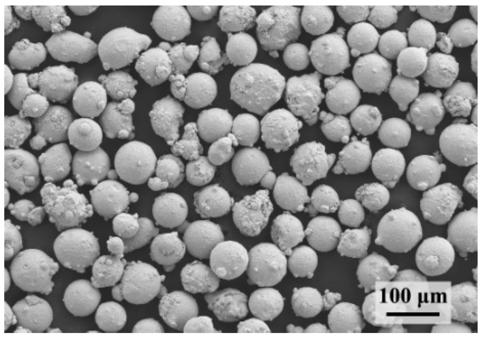
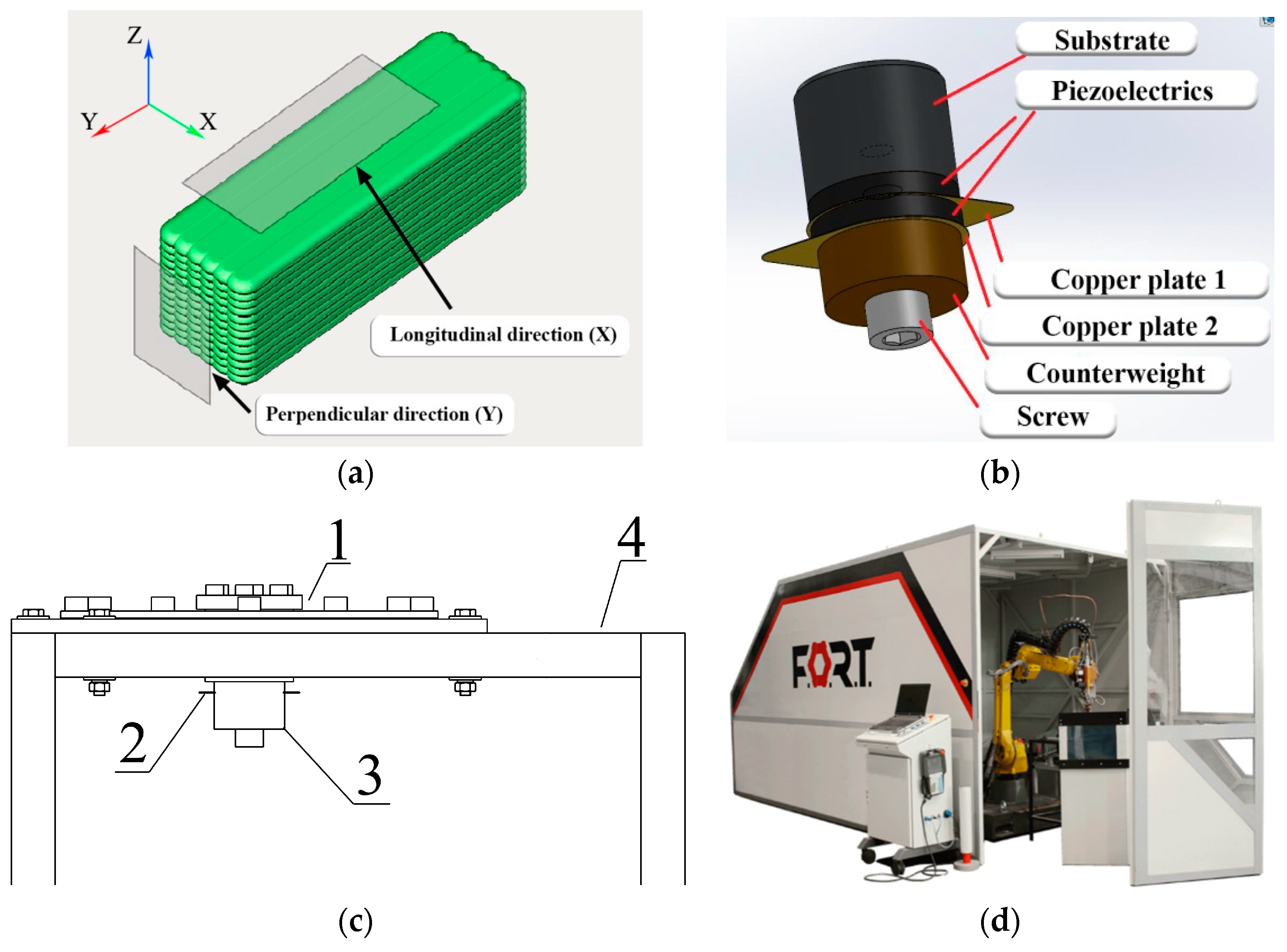
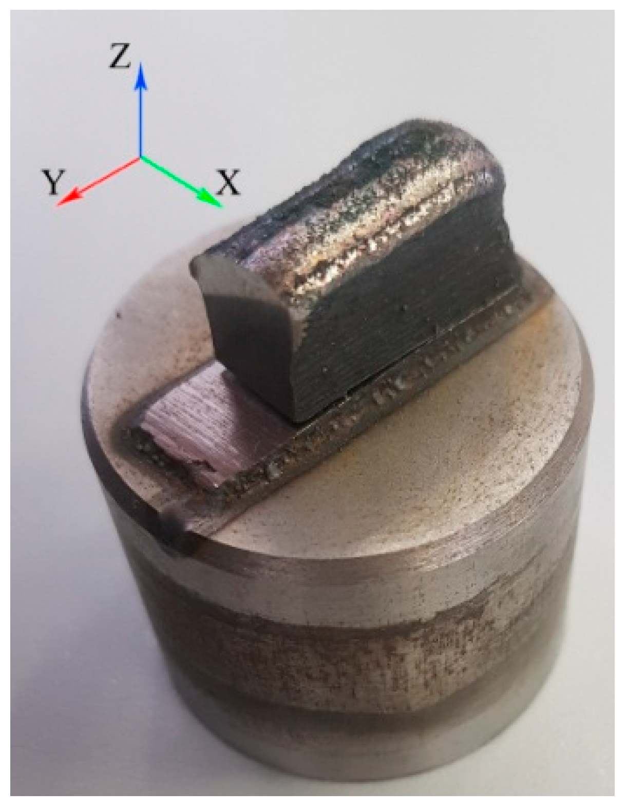
2.1. L-DED Processing
2.2. Characterization
3. Results and Discussion
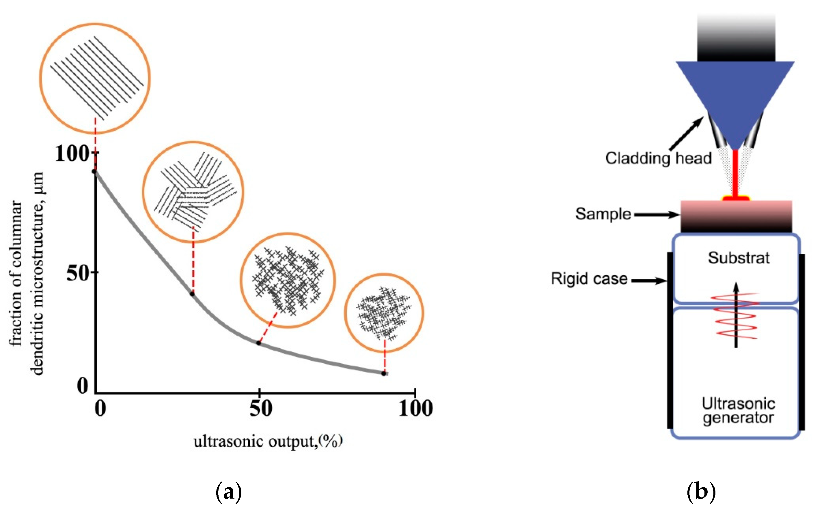
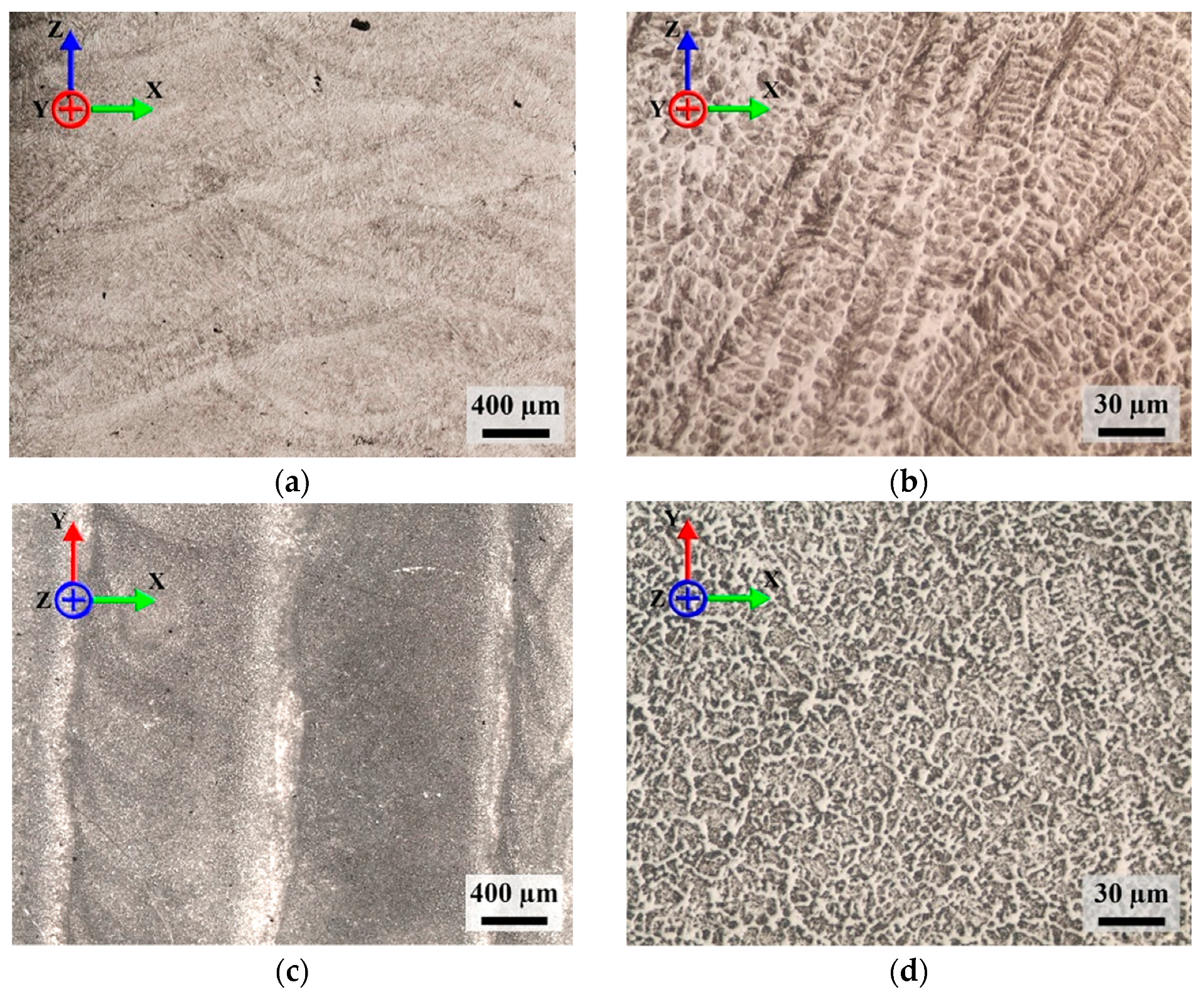
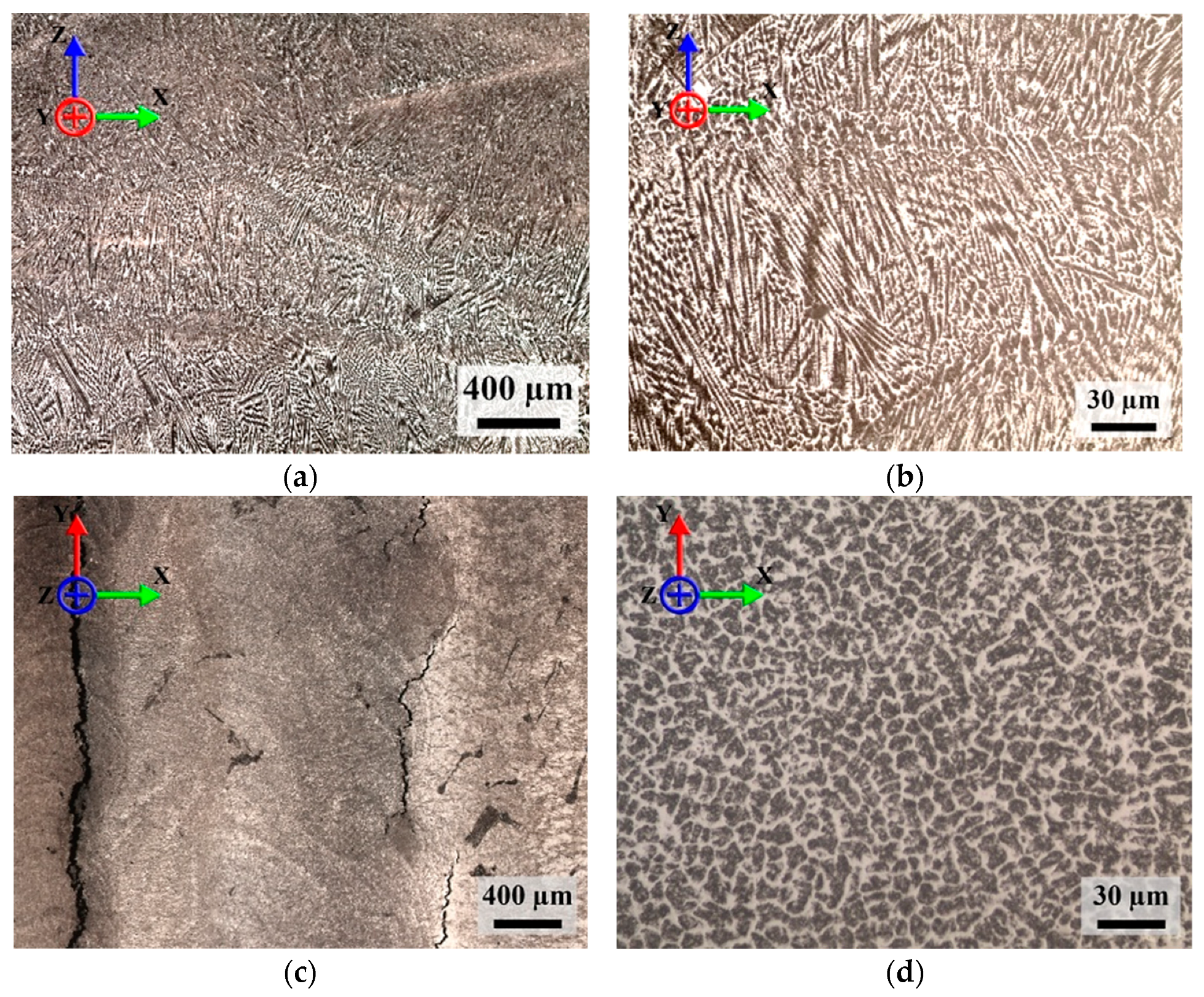
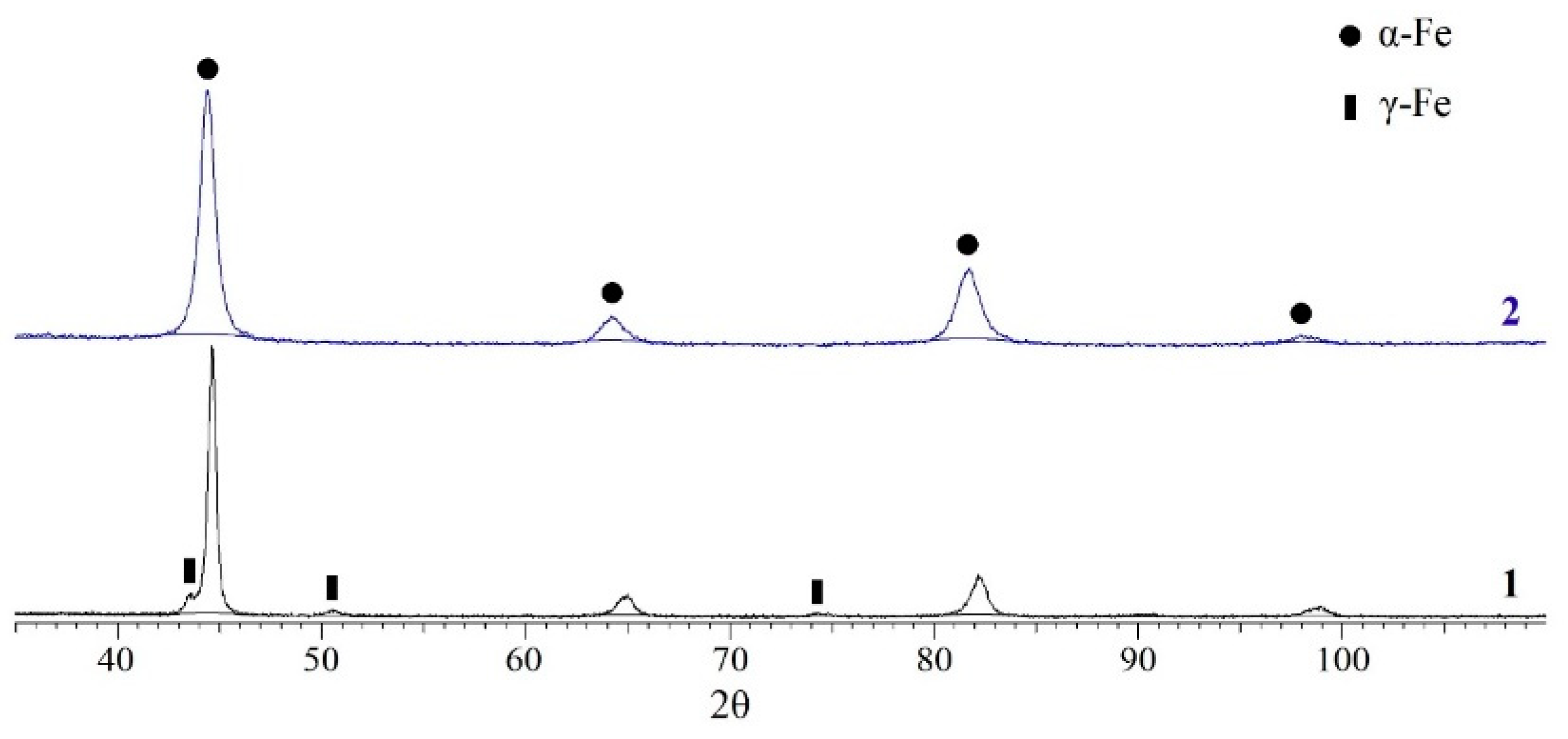
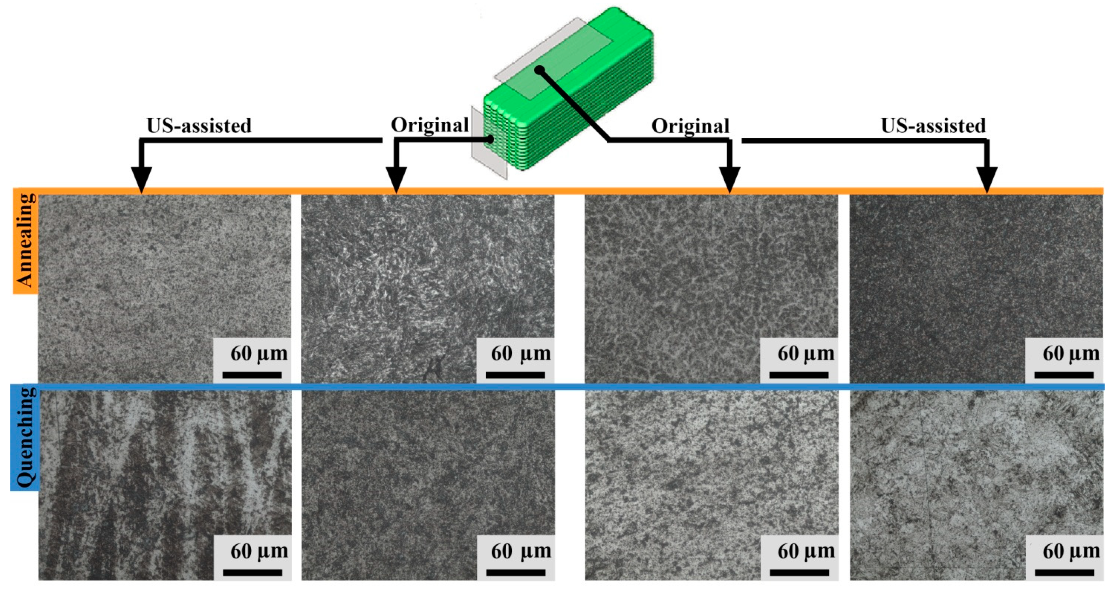
3.1. Effect of US on the Microstructural Characteristics
3.2. Effect of Heat Treatment on the Microstructural Characteristics
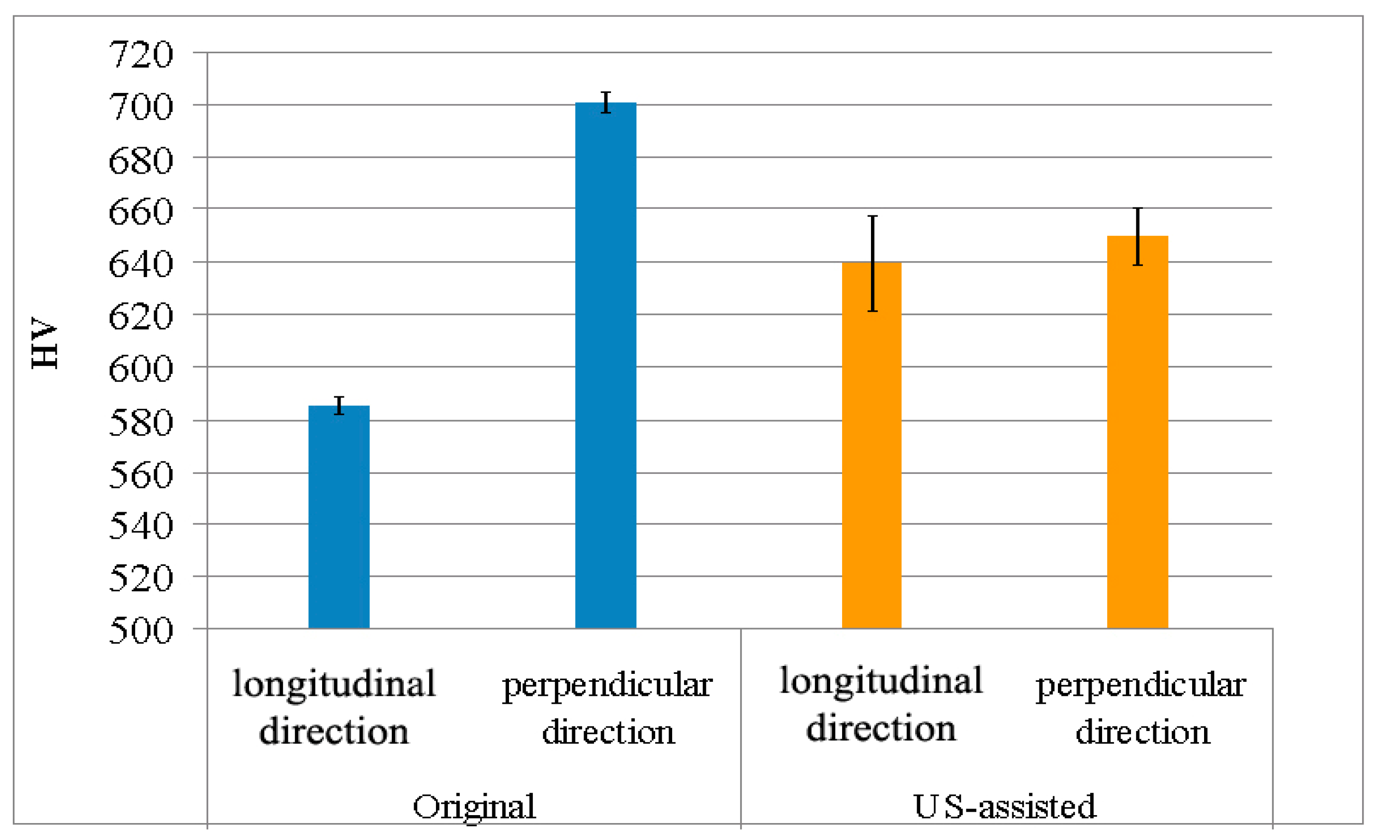
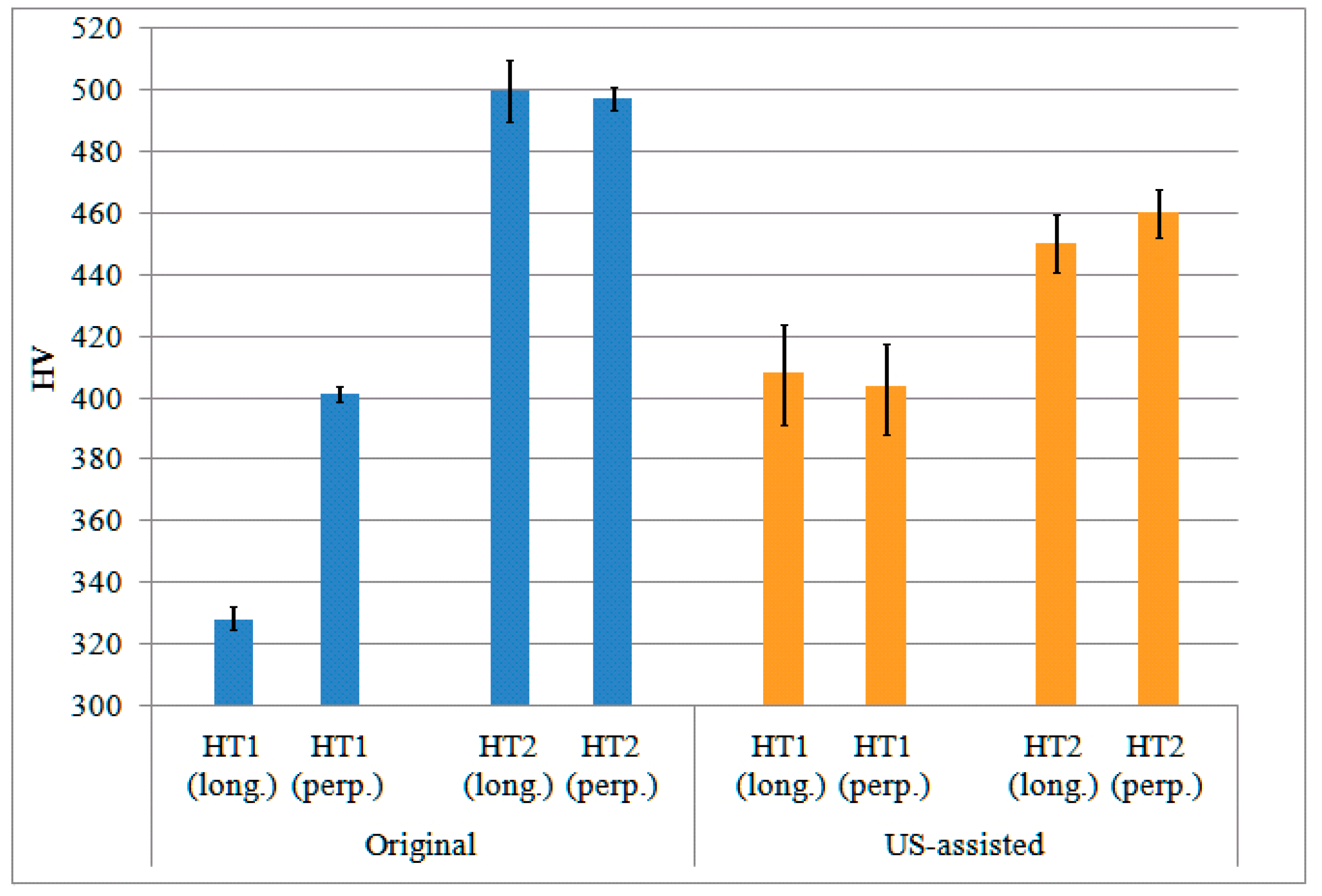
3.3. Effect of US and Heat Treatment on the Hardness Behavior
4. Conclusions
- H13 tool steel shows a more refined equiaxed microstructure with an increased number of third-order dendrites.
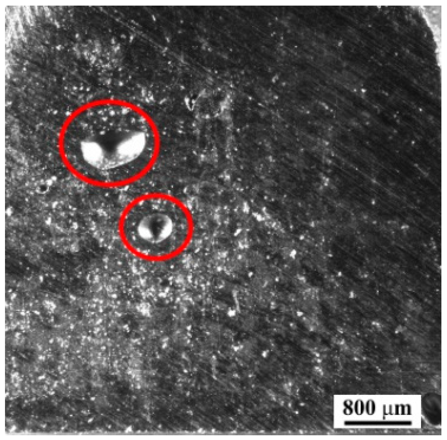
- There are no “keyhole” defects, which are often present in the molten conventional L-DED material.
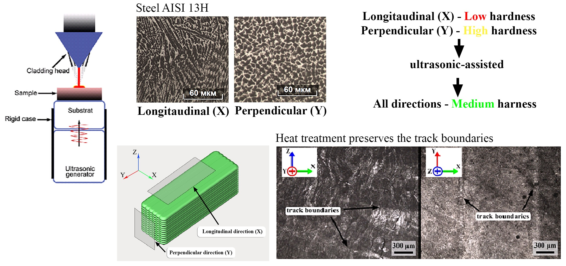
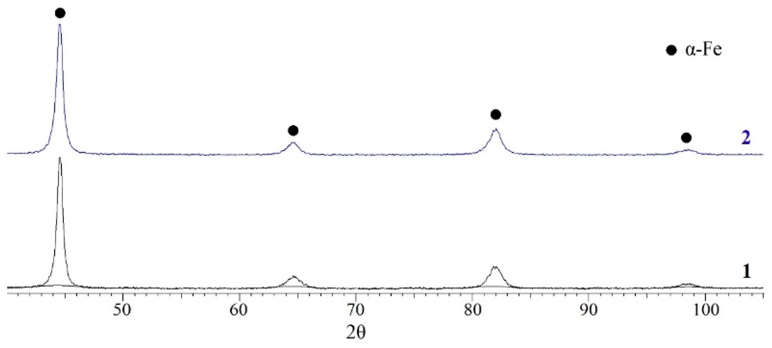
- It was found that US-assisted L-DED allows us to obtain a more isotropic structure with an equal size of the coherent scattering region in two printing directions, and to reduce the residual stresses in the material.
- The difference in the anisotropy of the properties in hardness is 1% with 636 and 640 HV (56 HRC both) for the perpendicular and parallel directions, respectively. Without US assistance, it is 581 ± 3 HV0.5 (54 HRC) for the longitudinal direction and 700 ± 4 HV0.5 (59 HRC) for the perpendicular direction, resulting in a 20% difference.
- Structural inheritance from the material modification induced by US affects the result of the heat treatment. Based on the obtained hardness data, it was noted that HT2 heat treatment can also result in a decrease in the anisotropy of the properties, similarly to the effect of US assistance.
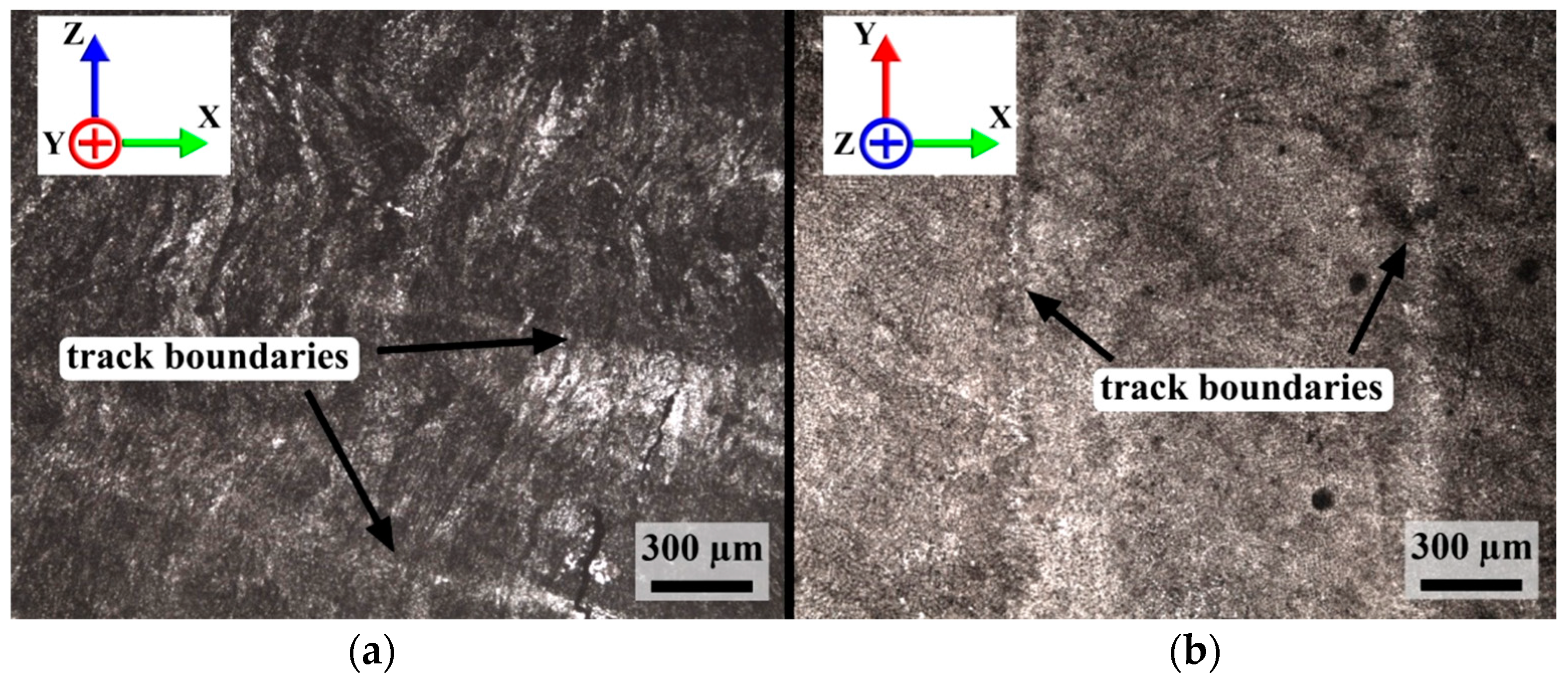
- Although US assistance showed very promising effects on the reduction of anisotropy and residual stresses, an adverse effect was also found in this work. It was found in the weakening of the inter-track bonding in a parallel direction and the formation of cracks at the boundary of two subsequent tracks. The US-assisted L-DED process parameters should thus be further optimized.
Author Contributions
Funding
Institutional Review Board Statement
Informed Consent Statement
Data Availability Statement
Conflicts of Interest
References
- Stevens, E.L.; Toman, J.; To, A.C.; Chmielus, M. Variation of hardness, microstructure, and Laves phase distribution in direct laser deposited alloy 718 cuboids. Mater. Des. 2017, 119, 188–198. [Google Scholar] [CrossRef] [Green Version]
- Clark, D.; Whittaker, M.T.; Bache, M.R. Microstructural characterization of a prototype titanium alloy structure processed via direct laser deposition (DLD). Metall. Mater. Trans. B Process. Metall. Mater. Process. Sci. 2012, 43, 388–396. [Google Scholar] [CrossRef] [Green Version]
- Dinda, G.P.; Dasgupta, A.K.; Mazumder, J. Laser aided direct metal deposition of Inconel 625 superalloy: Microstructural evolution and thermal stability. Mater. Sci. Eng. A 2009, 509, 98–104. [Google Scholar] [CrossRef]
- Guo, P.; Zou, B.; Huang, C.; Gao, H. Study on microstructure, mechanical properties and machinability of efficiently additive manufactured AISI 316L stainless steel by high-power direct laser deposition. J. Mater. Process. Technol. 2017, 240, 12–22. [Google Scholar] [CrossRef]
- Wang, L.; Xue, J.; Wang, Q. Correlation between arc mode, microstructure, and mechanical properties during wire arc additive manufacturing of 316L stainless steel. Mater. Sci. Eng. A 2019, 751, 183–190. [Google Scholar] [CrossRef]
- Liverani, E.; Toschi, S.; Ceschini, L.; Fortunato, A. Effect of selective laser melting (SLM) process parameters on microstructure and mechanical properties of 316L austenitic stainless steel. J. Mater. Process. Technol. 2017, 249, 255–263. [Google Scholar] [CrossRef]
- Wang, Q.; Zhang, S.; Zhang, C.H.; Wu, C.L.; Ren, L.; Wang, J.Q.; Chen, J. Functionally Graded Stainless Steel Fabricated by Direct Laser Deposition: Anisotropy of Mechanical Properties and Hardness. Acta Metall. Sin. 2018, 31, 19–26. [Google Scholar] [CrossRef] [Green Version]
- Lu, J.; Chang, L.; Wang, J.; Sang, L.; Wu, S.; Zhang, Y. In-situ investigation of the anisotropic mechanical properties of laser direct metal deposition Ti6Al4V alloy. Mater. Sci. Eng. A 2018, 712, 199–205. [Google Scholar] [CrossRef]
- Popovich, V.A.; Borisov, E.V.; Sufiyarov, V.S.; Popovich, A.A. Tailoring the Properties in Functionally Graded Alloy Inconel 718 Using Additive Technologies. Met. Sci. Heat Treat. 2019, 60, 701–709. [Google Scholar] [CrossRef]
- Deev, A.A.; Kuznetcov, P.A.; Petrov, S.N. Anisotropy of Mechanical Properties and its Correlation with the Structure of the Stainless Steel 316L Produced by the SLM Method. Phys. Procedia 2016, 83, 789–796. [Google Scholar] [CrossRef] [Green Version]
- Parimi, L.L.; Ravi, G.A.; Clark, D.; Attallah, M.M. Microstructural and texture development in direct laser fabricated IN718. Mater. Charact. 2014, 89, 102–111. [Google Scholar] [CrossRef]
- Shamsaei, N.; Yadollahi, A.; Bian, L.; Thompson, S.M. An overview of Direct Laser Deposition for additive manufacturing; Part II: Mechanical behavior, process parameter optimization and control. Addit. Manuf. 2015, 8, 12–35. [Google Scholar] [CrossRef]
- Richards, N.L.; Chaturvedi, M.C. Effect of minor elements on weldability of nickel base superalloys. Int. Mater. Rev. 2000, 45, 109–129. [Google Scholar] [CrossRef]
- Talaş, Ş. The assessment of carbon equivalent formulas in predicting the properties of steel weld metals. Mater. Des. 2010, 31, 2649–2653. [Google Scholar] [CrossRef]
- Watanabe, T.; Shiroki, M.; Yanagisawa, A.; Sasaki, T. Improvement of mechanical properties of ferritic stainless steel weld metal by US vibration. J. Mater. Process. Technol. 2010, 210, 1646–1651. [Google Scholar] [CrossRef]
- Gorunov, A.I.; Nyukhlaev, O.A.; Gilmutdinov, A.K. Investigation of microstructure and properties of low-carbon steel during US-assisted laser welding and cladding. Int. J. Adv. Manuf. Technol. 2018, 99, 2467–2479. [Google Scholar] [CrossRef]
- da Cunha, T.V.; Bohórquez, C.E.N. US in arc welding: A review. Ultrasonics 2015, 56, 201–209. [Google Scholar] [CrossRef]
- Sun, Q.J.; Lin, S.B.; Yang, C.L.; Zhao, G.Q. Penetration increase of AISI 304 using US assisted tungsten inert gas welding. Sci. Technol. Weld. Join. 2009, 14, 765–767. [Google Scholar] [CrossRef]
- Cui, Y.; Xu, C.; Han, Q. Microstructure Improvement in Weld Metal Using US Vibrations. Adv. Eng. Mater. 2007, 9, 161–163. [Google Scholar] [CrossRef]
- Ning, F.; Hu, Y.; Liu, Z.; Cong, W.; Li, Y.; Wang, X. US Vibration-Assisted Laser Engineered Net Shaping of Inconel 718 Parts: A Feasibility Study. Procedia Manuf. 2017, 10, 771–778. [Google Scholar] [CrossRef]
- Todaro, C.J.; Easton, M.A.; Qiu, D.; Zhang, D.; Bermingham, M.J.; Lui, E.W.; Brandt, M.; StJohn, D.H.; Qian, M. Grain structure control during metal 3D printing by high-intensity US. Nat. Commun. 2020, 11, 142. [Google Scholar] [CrossRef] [PubMed]
- Zhou, J.; Xu, J.; Huang, S.; Hu, Z.; Meng, X.; Fan, Y. Microstructure and mechanical properties of Cr12MoV by US vibration-assisted laser surface melting. Mater. Sci. Technol. 2017, 33, 1200–1207. [Google Scholar] [CrossRef]
- Masaylo, D.; Igoshin, S.; Popovich, A.; Popovich, V. Effect of process parameters on defects in large scale components manufactured by direct laser deposition. Mater. Today Proc. 2020, 30, 665–671. [Google Scholar] [CrossRef]
- Hu, G.; Yang, Y.; Lu, X.; Li, J. A study on the influence mechanism and optimization of physical field parameters of electromagnetic-ultrasonic compound field–assisted laser cladding technology. Weld. World 2021, 65, 1687–1700. [Google Scholar] [CrossRef]
- Yang, Z.; Zhu, L.; Wang, S.; Ning, J.; Dun, Y.; Meng, G.; Xue, P.; Xu, P.; Xin, B. Effects of ultrasound on multilayer forming mechanism of Inconel 718 in directed energy deposition. Addit. Manuf. 2021, 48, 102462. [Google Scholar] [CrossRef]


| Elements | Fe | C | Si | Mn | Cr | Mo | V |
|---|---|---|---|---|---|---|---|
| value | bal. | 0.40 | 1.00 | 0.48 | 5.30 | 1.30 | 1.00 |
| Sample | a, (Å) | CSR, (nm) | e0 |
|---|---|---|---|
| without US_perp | 2.891 | 14 | 0.005 |
| without US_long | 2.874 | >200 | 0.004 |
| with US_perp | 2.883 | 42 | 0.005 |
| with US_long | 2.883 | 48 | 0.006 |
Publisher’s Note: MDPI stays neutral with regard to jurisdictional claims in published maps and institutional affiliations. |
© 2022 by the authors. Licensee MDPI, Basel, Switzerland. This article is an open access article distributed under the terms and conditions of the Creative Commons Attribution (CC BY) license (https://creativecommons.org/licenses/by/4.0/).
Share and Cite
Masaylo, D.; Igoshin, S.; Popovich, A.; Orlov, A.; Kim, A.; Popovich, V. Microstructural and Hardness Behavior of H13 Tool Steel Manufactured by Ultrasound-Assisted Laser-Directed Energy Deposition. Metals 2022, 12, 450. https://doi.org/10.3390/met12030450
Masaylo D, Igoshin S, Popovich A, Orlov A, Kim A, Popovich V. Microstructural and Hardness Behavior of H13 Tool Steel Manufactured by Ultrasound-Assisted Laser-Directed Energy Deposition. Metals. 2022; 12(3):450. https://doi.org/10.3390/met12030450
Chicago/Turabian StyleMasaylo, Dmitriy, Sergei Igoshin, Anatoly Popovich, Alexey Orlov, Artem Kim, and Vera Popovich. 2022. "Microstructural and Hardness Behavior of H13 Tool Steel Manufactured by Ultrasound-Assisted Laser-Directed Energy Deposition" Metals 12, no. 3: 450. https://doi.org/10.3390/met12030450