Article

Process Parameters Optimisation for Mitigating Residual Stress in Dual-Laser Beam Powder Bed Fusion Additive Manufacturing

Department of Mechanical, Manufacturing & Biomedical Engineering, Trinity College Dublin, The University of Dublin, Parsons Building, D02 PN40 Dublin, Ireland
*
Authors to whom correspondence should be addressed.
Metals 2022, 12(3), 420; https://doi.org/10.3390/met12030420
Submission received: 4 February 2022 / Revised: 24 February 2022 / Accepted: 25 February 2022 / Published: 27 February 2022
(This article belongs to the Special Issue Additive Manufacturing of Non-ferrous Alloys)

Abstract

:
Laser beam powder bed fusion (PBF-LB) additive manufacturing (AM) is an advanced manufacturing technology that manufactures metal components in a layer-by-layer manner. The thermal residual stress (RS) induced by the repeated heating–melting–cooling–solidification processes of AM is considered to limit the wider uptake of PBF-LB. A dual-laser beam PBF-LB strategy, with an additional auxiliary laser and reduced power, working in the same powder bed simultaneously, was recently proposed to lower RS within the manufactured components. To provide insights into the optimum PBF-LB AM configurations and process parameters for dual-laser PBF-LB, this study proposed three different coordinated heating strategies (i.e., parallel heating, post-heating, and preheating) of the auxiliary heat source. The temperature fields and RS of dual-laser beam PBF-LB, for Ti-6Al-4V with different process parameters, were computationally investigated and optimized by the thermo-mechanically coupled 3D models. Compared with the single beam PBF-LB, parallel heating, post-heating, and post-heating strategies were proved as effective approaches to reduce RS. Among these, the preheating scanning is predicted to be more effective in mitigating RS, i.e., up to a 10.41% RS reduction, compared with the single laser scanning. This work could be beneficial for mitigating RS and improve the mechanical properties of additively manufactured metal components.

1. Introduction

Laser beam powder bed fusion (PBF-LB) is one of the most commonly used additive manufacturing (AM) technologies for bespoke component (e.g., orthopedic implant) manufacturing in industry [1,2,3]. PBF-LB manufactures components in a layer-by-layer manner and a moving heat source scans the predefined 2D cross section within each individual thin layer (e.g., in the order of micron). The repeated heating–melting–cooling–solidification processes during PBF-LB induce intricate thermal residual stress (RS) within additively manufactured components. RS can cause distortion and delamination of PBF-LB manufactured components and it is, therefore, necessary to reduce RS [4].
A variety of strategies have been widely investigated to reduce RS, such as process parameters [4,5], base plate preheating [6,7], and structure optimization [8]. For better control of the thermal history, microstructure, and mitigation of the RS [9], a novel dual-laser beam PBF-LB was recently presented as a promising technique [10], where a laser beam (which works as a main melting laser) with enough power to melt the powders and a secondary laser (which acts as an auxiliary heat source) with reduced power to slow the cooling process during PBF-LB. With dual-laser beams working simultaneously on the same powder bed, the total energy input and cooling rate could be significantly changed in dual-laser PBF-LB, compared to that of the single laser PBF-LB. Heeling et al. [11] noted that the secondary beam could heat the regions surrounding the melt pool, thus decreasing the cooling speed during PBF-LB. The modifications in the temperature history can further influence the temperature gradient and, thus, the final RS.
Finite element modelling provides capabilities to fully understand the RS formation mechanisms during PBF-LB. Lu et al. [6] computationally investigated approaches to mitigate the RS and warpage of Ti-6Al-4V components in PBF-LB, and the results indicated shortening the scanning vector and preheating the base plate could effectively reduce RS by 85.2% [12]. Cheng et al. [13] numerically studied the influences of eight different scanning strategies on temperature, RS, and deformation by a moving Gaussian heat source method, and the results showed that island scanning produced the maximum peak temperature, due to the residual heat effect within the short scanning path, and the 45° line scanning resulted the lowest build direction deformation and RS, compared with other scanning strategies.
Significant advances have been made in multi-laser beam PBF-LB. Masoomi et al. [14] investigated the influences of the laser beam number (1, 2, and 4) on the temperature and properties of the manufactured parts and concluded that the production times, cooling rates, and RS magnitudes decreased when increasing the number of laser beams. Zhang et al. [15] examined the effects of scanning strategies on temperature, RS, and deflection, and the results indicated that multi-laser beam PBF-LB could mitigate the maximum RS by 16.5%, compared with that of the single laser PBF-LB. Heeling et al. [16] investigated the melt pool characteristic of multi-beam PBF-LB by using a high speed camera, and the addition of a preheating laser was proved to effectively reduce the spatter phenomenon.
The build process parameters, such as energy beam power and moving speed, influence the RS within additively manufactured components and have been widely investigated in the single laser beam PBF-LB [5,17]. Upon examining the current literature, however, there was no study that was focused on the optimization of the process parameters in multi-laser PBF-LB to mitigate RS. In order to provide insights into the optimum process parameters and configurations, a detailed understanding of the dual-laser PBF-LB process is required to obtain the RS information and inform AM designers and operators of the optimum setup during the physical dual-laser PBF-LB printing.

2. Computational Modelling Methods

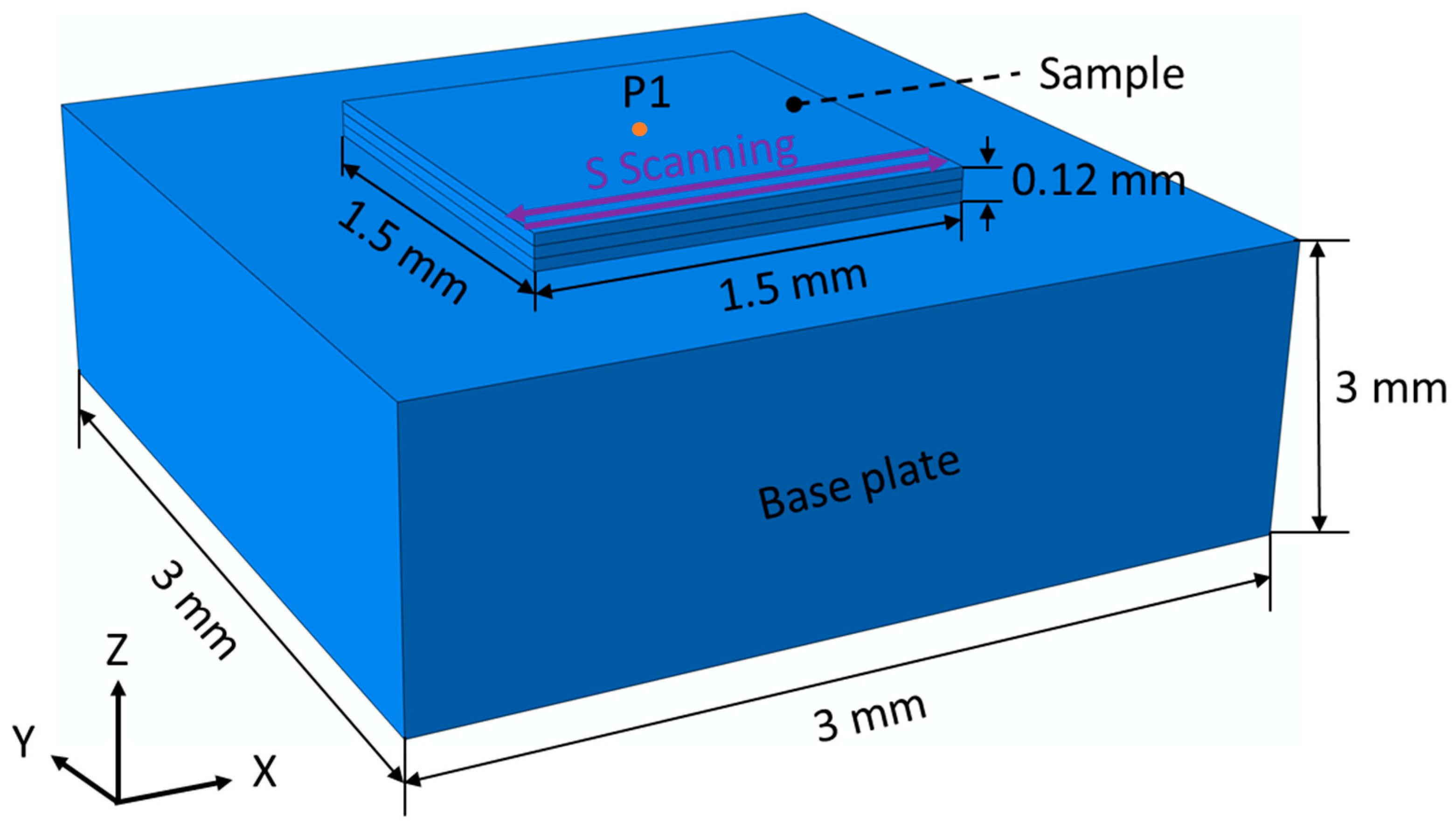
2.1. Model Configurations

For computational efficiency and the convenience of the computational modelling in this study, the PBF-LB AM model for the dual-laser beam PBF-LB is simplified to include a 1.5 × 1.5 × 0.12 mm3 Ti-6Al-4V sample that is deposited on a 3 × 3 × 1 mm3 base plate (Figure 1). The initial temperature of the whole system was set as 293 K. The coupled thermo-mechanical modelling was performed on the general-purpose finite element analysis software ABAQUS (Dassault Systèmes, Providence, RI, USA, 2019). To simulate the layer-by-layer manufacturing process of the physical PBF-LB, a PYTHON script was programmed to slice the 3D geometry into individual layers [15,18]. The ’model change’ function in ABAQUS was employed to simulate the gradual deposition of a layer. The converged mesh size of 20 × 20 × 20 µm3 for the sample [15,19] and coupled thermo-mechanical element type of C3D8T in ABAQUS were used for the computational model.
The three different types of dual-laser beam PBF-LB were originally from references [9,16]: parallel heating (Figure 2a), post-heating (Figure 2b), and preheating (Figure 2c). For the dual-laser beam PBF-LB, two laser beams are employed to scan the same powder bed with a specified offset distance. For the parallel heating mode, the offset is perpendicular to the scanning direction. The secondary laser follows the first laser with a time delay for the post-heating models, and, in preheating, the auxiliary laser scans prior to the melting laser. The offset of the auxiliary laser beam spot center to the melting laser center, along the x direction, is defined as ∆x, and ∆y indicates a distance of the two laser beams along the y direction. To simulate the localised moving heat source, a FORTRAN subroutine for a Gaussian distributed heat profile in ABAQUS was programmed and employed. The “S” scanning strategy was employed in PBF-LB process modelling and rotated 90° for the subsequent layer (Figure 3). The cooling rate (CR) at the centre of the top layer (P1 shown Figure 1) was investigated.

2.2. Thermal Transfer and Mechanical Mechanisms

The thermal transfer mechanisms during PBF-LB process modelling include conduction to the previously solidified material and base plate, conduction from the solidified layers to the surrounding loose powders [20], and convection and radiation from the top surface of the active layer (which refers to the newly added layer of material) to the surrounding atmosphere. Details of the heat transfer mechanisms are shown in the authors’ previous publications [18,20].
The energy equation that is employed in the fully coupled thermo-mechanical process modelling for the PBF-LB process is [18,21,22,23]:
H ˙ + · q = Q + D ˙ m e c h
where H ˙ is the rate of enthalpy change (per unit volume), q for the heat flux, Q for the power density of laser beam heating, and D ˙ m e c h for the thermal-stress dissipation rate caused by the plastic deformation [18,24,25]. The enthalpy rate can be stated as:
H ˙ = ρ s C p d T d t + ρ s d ( f L ) d t
where ρ s for density of solid material, C p for specific heat capacity, T for temperature, t for time, and L for latent heat of fusion. The liquid fraction f is assumed to be a linear function of temperature as [26]:
f = { 0   T < T S T T S T L T S   T S T T L 1   T > T L
where T S and T L are the solidus and liquidus temperature, respectively.
The volumetric Gaussian distributed power density can be formulated as:
Q = 4 2 A P π π R 3 e 2 r 2 R 2
where A is heat source absorption coefficient, P is laser beam power, R is laser spot radius, and r is the distance to the laser beam centre. The single laser beam PBF-LB and three different modes of coordinated Gaussian-distributed heat sources for the dual-laser beam PBF-LB are shown in Figure 4.
The heat flux due to conduction can be expressed as [27]:
q c o n d = k s T
where k s is the temperature-dependent thermal conductivity of the solid material. The radiation heat loss from the top surface of the active layer to the surrounding atmosphere can be defined by Stefan–Boltzmann’s law before the next layer is added [18]:
q r a d = ε σ S ( T s u r 4 T r 4 )
where q r a d is the heat flux due to active layer radiation, ε is the emissivity, σ S is the Stefan–Boltzmann constant, T s u r is the surface temperature of the computational model, and T r is the build chamber temperature [28].
The active layer convection heat dispersion between the top surface of the active layer to the surrounding environment can be expressed by Newton’s law of cooling [18,20]:
q c o n v = h ( T s u r T r )
where h is the heat transfer coefficient.
The equilibrium for the finite element mechanical analysis is given by:
∇ · σ = 0
where σ is the stress tensor. The mechanical constitutive law for the elastic problem is defined as:
σ = C : ε e
where C is the material stiffness tensor, and εe is the elastic strain tensor. The total strain rate can be represented as:
ε ˙ T o t a l = ε ˙ e + ε ˙ p + ε ˙ T
where εTotal, εe, εp, and εT are the total, the elastic, plastic, and thermal strain, respectively. The thermal strain component is given by:
Δ ε T = α Δ T
where α is the coefficient of thermal expansion of material. Δ T is the change of temperature.

2.3. Process Parameters and Material Properties

The process parameters, such as laser spot diameter and scanning speed, applied in the PBF-LB modelling is shown in Table 1. The temperature-dependent material properties of Ti-6Al-4V were employed for both the sample and base plate [15]. To optimize the process parameters during the dual-laser PBF-LB, a list of process parameters with variations of laser beam power and distance between the secondary laser beam centre and main melting laser spot centre for the three modes (Figure 2) were employed, as shown in Table 2. The laser beams offset distance (∆x and ∆y, Figure 2) is designed based on the laser spot diameter of 0.1 mm [11], e.g., the parallel scanning case (e) in Table 2 has a y offset of 0.2 mm, which is two times of the laser spot diameter. The applied process parameters in Table 2 are expected to produce nearly fully dense Ti-6Al-4V samples [29].

3. Results and Discussions

3.1. Temperature Profiles

The computational modelling results of temperature contours by different build parameters (i.e., the cases listed on Table 2) and scanning models are shown in Figure 5. The temperature contours, at half of the total time needed for a layer scanning of the top layer, was plotted to show and compare the temperature fields of all the models [13,15]. The peak temperature (i.e., maximum temperature during the entire manufacturing process) for all scanning cases is demonstrated in Figure 6. Different scanning modes and process parameters generated quite different temperature fields (Figure 5), which were induced by the different scanning trajectories of laser beams. The similar temperature field of single laser beam PBF-LB was found elsewhere [30], but the predicted peak temperature of this study is higher than the reference, due to the addition of the secondary laser. The single laser beam scanning (Figure 6a) produced a lower temperature than other cases (Figure 6b–m), e.g., the preheating mode with a laser power of 60 W and an offset distance of 100 µm (Figure 6c, 3138 K) generated a marginally 5.73% higher peak temperature than that of the single laser beam (Figure 6a, 2968 K).
Comparing all the modelling cases, the post-heating mode generally produced a higher temperature than other models (preheating and parallel heating). This is because of the high temperature of the regions in the vicinity of the melt pool when the secondary laser beam scans, due to the short distance between the melting and secondary laser beam (≤200 µm). For the post-heating models with post laser power of 60 W and 90 W and laser beam offset of 100 µm (Figure 5k,l), the secondary laser beam produced a higher peak temperature than the first melting laser beam, even though the delayed laser was with a reduced power compared with the melting laser. Note that several of the predicted peak temperatures (Figure 6h,k–m) exceeded the boiling temperature (3133 K) of Ti-6Al-4V material [31], which also occurred during physical manufacturing [32]. The predicted peak temperature of the majority of the material was below the boiling temperature of material.
In order to enhance the visibility of the figure and compare temperature for different models and process parameters more clearly, the temperature evolution between 20.05 and 20.06 s was collected, which is around half the time required to melt the top layer (Figure 7). The temperature temporal evolutions for multi-laser PBF models (Figure 7b–m) are different from that of the single laser scanning (Figure 7a). The temperature oscillates with the moving of the laser beams and then starts to monotonically decrease when the laser beam moves far away from the P1 position. When the power of the auxiliary laser is high, the temperature of the parallel scanning could partially melt the material (Figure 7c–e): this phenomenon also occurred for the preheating (Figure 7g–i). It is interesting to observe that, for the post-heating, the followed laser beam produced a higher peak temperature than the first laser beam (Figure 7l); this is because of the short offset (i.e., 100 µm) between two laser beams, and the temperature of the material was still high, when the following laser scanned.

3.2. Cooling Rate

Figure 8 demonstrates that the CR at P1 (Figure 1) is in the order of magnitude of 105–106 K/s, which is calculated based on the time required for the temperature of material at P1 (Figure 1) to cool from the melting point of Ti-6Al-4V to the β-transus temperature of 1270 K [33]. It is close to the practically measured results of 105~106 K/s, in other PBF-LB studies [34,35]. It can be seen, as shown in Figure 8, that the CR is highest for the single laser scanning (Figure 8a), compared with other multi-laser manufacturing (Figure 8b–l), which indicates the auxiliary laser beam is beneficial for reducing the RS. This indicates that the auxiliary laser beam heats the material surrounding the melt pool, slowing down the cooling process, which is consistent with reference [11]. With a constant distance between two laser beams, the CR decreases with the increase of laser power. For instance, the CR of the preheating model, with a laser power of 90 W (8.27 × 10⁵ K/s, Figure 8h), was 39.10% less than that of the 30 W (13.58 × 10⁵ K/s, Figure 8g) case. This is because the higher laser power caused higher energy density, which makes for a more uniformly distributed temperature field of the powder bed.

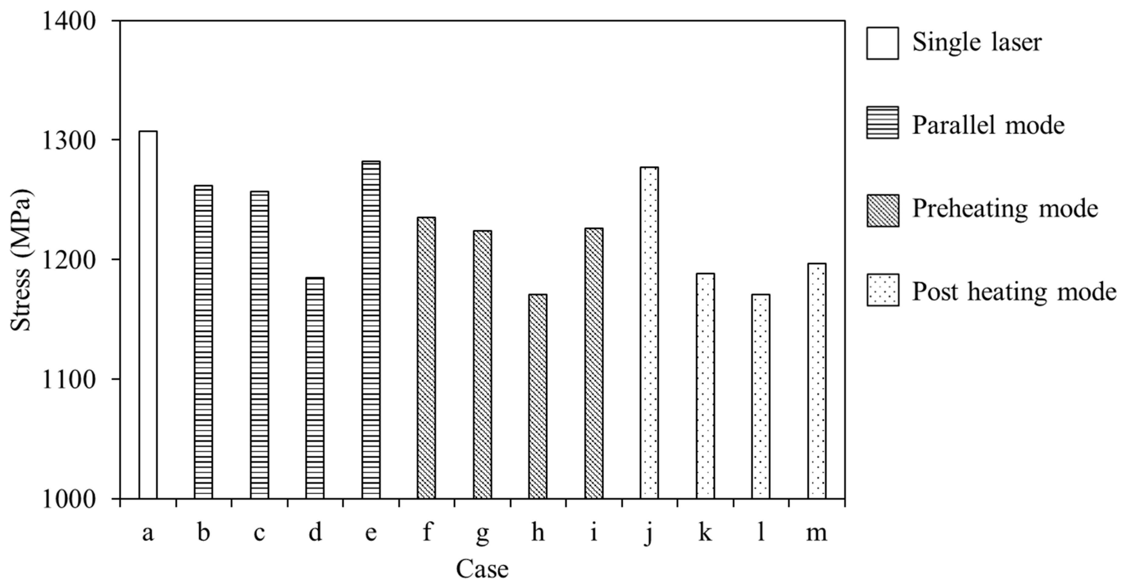
3.3. Residual Stress

The RS contours for different coordinated dual-laser beam scanning modes and process parameters are shown in Figure 9. Similar RS distributions are formed for the different computational models (Figure 9), but with different RS magnitudes (Figure 10). For all the computational modelling cases (Figure 9), the largest von Mises RS occurs at the bottom of part (i.e., the interface between the part and the build plate), which is also found elsewhere [36]. This is because the shinkage of the part was constrained by the base plate at the post manufacturing cooling process. Among all the prediction cases, the least maximum RS of 1171 MPa (Figure 10l) was generated by the post-heating with a laser power of 90 W and offset of 100 µm, which is reduced by 10.41%, compared to the single laser scanning (1307 MPa, Figure 10a). The RS could be further reduced by increasing the number of laser beams [15]. In addition, Figure 10 indicates that the higher the laser power applied, the lower the RS induced, which is consistent with the computational modelling results of the CR (Figure 8). This phenomenon is due to the uniformity of the powder bed, which causes a lower temperature gradient and CR and is consistent with studies elsewhere [5,17,37].

4. Conclusions

In this study, three different types of coordinated dual-laser PBF-LB were optimized and compared with the single laser PBF-LB by full coupled thermo-mechanical modelling. The effects of different types of a secondary heating source on thermal (temperature and cooling rate) and mechanical behavior (RS) of Ti-6Al-4V were computationally investigated. The key conclusions are:
  • Compared with the single laser scanning, an additional auxiliary laser with preheating, post-heating, or parallel mode can mitigate RS.
  • The post-heating mode scanning can more effectively reduce RS than the preheating and parallel heating strategies.
  • With the addition of the secondary laser beam in coordinated dual-laser PBF-LB, the peak temperature increases, while the cooling rate and RS decrease.
  • The maximum RS can be reduced by up to 10.41% when using the secondary laser beam with reduced laser power, compared with the single laser beam scanning.
Further work will be focused on experimental RS validation on parts manufactured by multi-laser beam AM and with different build parameters.

Author Contributions

Conceptualization, W.Z.; methodology, software, and investigation, W.Z., W.M.A. and A.S.; writing—original draft preparation, W.Z.; writing—review and editing, W.Z., W.M.A., A.S. and R.L.; supervision, R.L.; project technical administration, R.L. All authors have read and agreed to the published version of the manuscript.

Funding

This research was funded by the Enterprise Ireland, project number CF-2020-1564-A. This work was also supported by Science Foundation Ireland 18/EPSRC-CDT/3581 and the Engineering and Physical Sciences Research Council, EP/S023259/1.

Institutional Review Board Statement

Not applicable.

Informed Consent Statement

Not applicable.

Data Availability Statement

Data are contained within the article.

Acknowledgments

The authors grateful acknowledge the funding by the Enterprise Ireland. The authors wish to acknowledge the Irish Centre for High-End Computing (ICHEC) for the provision of computational facilities and support.

Conflicts of Interest

The authors declare no conflict of interest.

References

  1. Bartlett, J.L.; Li, X. An overview of residual stresses in metal powder bed fusion. Addit. Manuf. 2019, 27, 131–149. [Google Scholar] [CrossRef]
  2. Seifi, M.; Salem, A.; Beuth, J.; Harrysson, O.; Lewandowski, J.J. Overview of Materials Qualification Needs for Metal Additive Manufacturing. JOM 2016, 68, 747–764. [Google Scholar] [CrossRef] [Green Version]
  3. King, W.E.; Anderson, A.T.; Ferencz, R.M.; Hodge, N.E.; Kamath, C.; Khairallah, S.A.; Rubenchik, A.M. Laser powder bed fusion additive manufacturing of metals; physics, computational, and materials challenges. Appl. Phys. Rev. 2015, 2, 041304. [Google Scholar] [CrossRef]
  4. Roberts, I.A. Investigation of Residual Stresses in the Laser Melting of Metal Powders in Additive Layer Manufacturing. Ph.D. Thesis, University of Wolverhampton, Wolverhampton, UK, 2012. [Google Scholar]
  5. Levkulich, N.C.; Semiatin, S.L.; Gockel, J.E.; Middendorf, J.R.; DeWald, A.T.; Klingbeil, N.W. The effect of process parameters on residual stress evolution and distortion in the laser powder bed fusion of Ti-6Al-4V. Addit. Manuf. 2019, 28, 475–484. [Google Scholar] [CrossRef]
  6. Lu, X.; Cervera, M.; Chiumenti, M.; Li, J.; Ji, X.; Zhang, G.; Lin, X. Modeling of the Effect of the Building Strategy on the Thermomechanical Response of Ti-6Al-4V Rectangular Parts Manufactured by Laser Directed Energy Deposition. Metals 2020, 10, 1643. [Google Scholar] [CrossRef]
  7. Dunbar, A.J.; Denlinger, E.R.; Gouge, M.F.; Simpson, T.W.; Michaleris, P. Comparisons of laser powder bed fusion additive manufacturing builds through experimental in situ distortion and temperature measurements. Addit. Manuf. 2017, 15, 57–65. [Google Scholar] [CrossRef]
  8. Lu, X.; Chiumenti, M.; Cervera, M.; Li, J.; Lin, X.; Ma, L.; Zhang, G.; Liang, E. Substrate design to minimize residual stresses in Directed Energy Deposition AM processes. Mater. Des. 2021, 202, 109525. [Google Scholar] [CrossRef]
  9. Evans, R.; Gockel, J. Modeling the Effects of Coordinated Multi-Beam Additive Manufacturing. Int. J. Adv. Manuf. Technol. 2021, 115, 1075–1087. [Google Scholar] [CrossRef]
  10. Mugwagwa, L.; Yadroitsava, I.; Makoana, N.; Yadroitsev, I. Residual stress in laser powder bed fusion. In Fundamentals of Laser Powder Bed Fusion of Metals; Elsevier: Amsterdam, The Netherlands, 2021; pp. 245–276. [Google Scholar]
  11. Heeling, T.; Wegener, K. The effect of multi-beam strategies on selective laser melting of stainless steel 316L. Addit. Manuf. 2018, 22, 334–342. [Google Scholar] [CrossRef]
  12. Lu, X.; Lin, X.; Chiumenti, M.; Cervera, M.; Hu, Y.; Ji, X.; Ma, L.; Yang, H.; Huang, W. Residual stress and distortion of rectangular and S-shaped Ti-6Al-4V parts by Directed Energy Deposition: Modelling and experimental calibration. Addit. Manuf. 2019, 26, 166–179. [Google Scholar] [CrossRef]
  13. Cheng, B.; Shrestha, S.; Chou, K. Stress and deformation evaluations of scanning strategy effect in selective laser melting. Addit. Manuf. 2016, 12, 240–251. [Google Scholar]
  14. Masoomi, M.; Thompson, S.M.; Shamsaei, N. Laser powder bed fusion of Ti-6Al-4V parts: Thermal modeling and mechanical implications. Int. J. Mach. Tools Manuf. 2017, 118, 73–90. [Google Scholar] [CrossRef] [Green Version]
  15. Zhang, W.; Tong, M.; Harrison, N.M. Scanning strategies effect on temperature, residual stress and deformation by multi-laser beam powder bed fusion manufacturing. Addit. Manuf. 2020, 36, 101507. [Google Scholar] [CrossRef]
  16. Heeling, T.; Gerstgrasser, M.; Wegener, K. Investigation of Selective Laser Melting Spatter Characteristics for Single- and Multi-Beam Strategies using High Speed Imaging. In Proceedings of the Lasers in Manufacturing Conference (LiM 2017), Munich, Germany, 26–29 June 2017. [Google Scholar]
  17. Wu, A.S.; Brown, D.W.; Kumar, M.; Gallegos, G.F.; King, W.E. An Experimental Investigation into Additive Manufacturing-Induced Residual Stresses in 316L Stainless Steel. Metall. Mater. Trans. A 2014, 45, 6260–6270. [Google Scholar] [CrossRef]
  18. Zhang, W.; Tong, M.; Harrison, N.M. Resolution, energy and time dependency on layer scaling in finite element modelling of laser beam powder bed fusion additive manufacturing. Addit. Manuf. 2019, 28, 610–620. [Google Scholar] [CrossRef]
  19. Wang, Q.; Zhang, W.; Li, S.; Tong, M.; Hou, W.; Wang, H.; Hao, Y.; Harrison, N.M.; Yang, R. Material Characterisation and Computational Thermal Modelling of Electron Beam Powder Bed Fusion Additive Manufacturing of Ti2448 Titanium Alloy. Materials 2021, 14, 7359. [Google Scholar] [CrossRef]
  20. Zhang, W.; Tong, M.; Harrison, N.M. Data on a computationally efficient approximation of part-powder conduction as surface free convection in powder bed fusion process modelling. Data Brief 2019, 27, 104559. [Google Scholar] [CrossRef]
  21. Galati, M.; Iuliano, L. A literature review of powder-based electron beam melting focusing on numerical simulations. Addit. Manuf. 2018, 19, 1–20. [Google Scholar] [CrossRef]
  22. Michaleris, P. Modeling metal deposition in heat transfer analyses of additive manufacturing processes. Finite Elem. Anal. Des. 2014, 86, 51–60. [Google Scholar] [CrossRef]
  23. Chiumenti, M.; Cervera, M.; Dialami, N.; Wu, B.; Jinwei, L.; de Saracibar, C.A. Numerical modeling of the electron beam welding and its experimental validation. Finite Elem. Anal. Des. 2016, 121, 118–133. [Google Scholar] [CrossRef] [Green Version]
  24. Abaqus Theory Guide 6.14; Dassault Systèmes: Providence, RI, USA, 2014.
  25. Chiumenti, M.; Cervera, M.; de Saracibar, C.A.; Dialami, N. Numerical modeling of friction stir welding processes. Comput. Methods Appl. Mech. Eng. 2013, 254, 353–369. [Google Scholar] [CrossRef]
  26. Bayat, M.; Mohanty, S.; Hattel, J.H. A systematic investigation of the effects of process parameters on heat and fluid flow and metallurgical conditions during laser-based powder bed fusion of Ti6Al4V alloy. Int. J. Heat Mass Transf. 2019, 139, 213–230. [Google Scholar] [CrossRef]
  27. Li, C.; Fu, C.H.; Guo, Y.B.; Fang, F.Z. A multiscale modeling approach for fast prediction of part distortion in selective laser melting. J. Mater. Process Tech. 2016, 229, 703–712. [Google Scholar] [CrossRef]
  28. Zhao, X.; Iyer, A.; Promoppatum, P.; Yao, S.-C. Numerical modeling of the thermal behavior and residual stress in the direct metal laser sintering process of titanium alloy products. Addit. Manuf. 2017, 14, 126–136. [Google Scholar] [CrossRef]
  29. Majumdar, T.; Bazin, T.; Ribeiro, E.M.C.; Frith, J.E.; Birbilis, N. Understanding the effects of PBF process parameter interplay on Ti-6Al-4V surface properties. PLoS ONE 2019, 14, e0221198. [Google Scholar] [CrossRef]
  30. Mede, T.; Kocjan, A.; Paulin, I.; Godec, M. Numerical Mesoscale Modelling of Microstructure Evolution during Selective Laser Melting. Metals 2020, 10, 800. [Google Scholar] [CrossRef]
  31. Zhang, G.; Chen, J.; Zheng, M.; Yan, Z.; Lu, X.; Lin, X.; Huang, W. Element Vaporization of Ti-6Al-4V Alloy during Selective Laser Melting. Metals 2020, 10, 435. [Google Scholar] [CrossRef] [Green Version]
  32. Hertel, M.; Trautmann, M.; Jäckel, S.; Füssel, U. The Role of Metal Vapour in Gas Metal Arc Welding and Methods of Combined Experimental and Numerical Process Analysis. Plasma Chem. Plasma Processing 2017, 37, 531–547. [Google Scholar] [CrossRef]
  33. Thampy, V.; Fong, A.Y.; Calta, N.P.; Wang, J.; Martin, A.A.; Depond, P.J.; Kiss, A.M.; Guss, G.; Xing, Q.; Ott, R.T.; et al. Subsurface Cooling Rates and Microstructural Response during Laser Based Metal Additive Manufacturing. Sci. Rep. 2020, 10, 1981. [Google Scholar] [CrossRef]
  34. Criales, L.E.; Arısoy, Y.M.; Lane, B.; Moylan, S.; Donmez, A.; Özel, T. Laser powder bed fusion of nickel alloy 625: Experimental investigations of effects of process parameters on melt pool size and shape with spatter analysis. Int. J. Mach. Tools Manuf. 2017, 121, 22–36. [Google Scholar] [CrossRef]
  35. Wang, Z.; Lin, X.; Kang, N.; Hu, Y.; Chen, J.; Huang, W. Strength-ductility synergy of selective laser melted Al-Mg-Sc-Zr alloy with a heterogeneous grain structure. Addit. Manuf. 2020, 34, 101260. [Google Scholar] [CrossRef]
  36. Tan, P.; Shen, F.; Li, B.; Zhou, K. A thermo-metallurgical-mechanical model for selective laser melting of Ti6Al4V. Mater. Des. 2019, 168, 107642. [Google Scholar] [CrossRef]
  37. Mukherjee, T.; Zhang, W.; DebRoy, T. An improved prediction of residual stresses and distortion in additive manufacturing. Comput. Mater. Sci. 2017, 126, 360–372. [Google Scholar] [CrossRef] [Green Version]
Figure 1. Model configurations.
Metals 12 00420 g001
Figure 2. Illustration of three different modes of a secondary laser beam: (a) parallel mode; (b) post-heating mode; and (c) preheating mode.
Metals 12 00420 g002
Figure 3. Illustration of the 90° rotation scanning strategy applied (adapted from [13,15]).
Metals 12 00420 g003
Figure 4. Illustration of the Gaussian distributed heat sources for PBF-LB modelling: (a) single laser beam for melting powders; (b) parallel of an auxiliary heat source; (c) preheating of an auxiliary heat source; and (d) post-heating of an auxiliary heat source (z = 0).
Metals 12 00420 g004
Figure 5. Temperature contours (logarithmic scale) at half of the total time needed for a layer scanning of the top layer for different scanning modes and process parameters using the 90° rotation scanning strategy (Figure 3): (a) single laser beam; (be) parallel model; (fi) preheating mode; (jm) post-heating mode. (b,f,g) With a laser power of 30 W; (c,g,k) with a laser power of 60 W; (d,h,l) with a laser power of 90 W and a distance of 100 µm between two lasers; (e,i,m) with a laser power of 60 W and an offset of 200 µm between two lasers. The base plate was involved in the modelling, but not shown in this figure.
Metals 12 00420 g005
Figure 6. Peak temperature for different scanning modes and process parameters: (a) single laser beam; (be) parallel model; (fi) preheating mode; (jm) post-heating mode.
Metals 12 00420 g006
Figure 7. Temperature history for different scanning modes and process parameters: (a) single laser beam; (be) parallel model; (fi) preheating mode; (jm) post-heating mode.
Metals 12 00420 g007
Figure 8. Cooling rate at the P1 position of model (Figure 1) by different scanning modes and process parameters: (a) single laser beam; (be) parallel model; (fi) preheating mode; and (jm) post-heating mode.
Metals 12 00420 g008
Figure 9. Residual von Mises stress contours for different scanning modes and process parameters: (a) single laser beam; (be) parallel model; (fi) preheating mode; and (jm) post-heating mode.
Metals 12 00420 g009
Figure 10. The peak residual stress for different scanning modes and process parameters: (a) single laser beam; (be) parallel model; (fi) preheating mode; and (jm) post-heating mode.
Metals 12 00420 g010
Table 1. Process parameters used for computational PBF-LB process modelling (data from [15]).
Spot Diameter (mm)Scanning Speed (m/s)Hatch Spacing
(mm)
Layer Thickness (µm)
0.11.20.140
Table 2. Process parameters applied for the single laser beam and different strategies of dual-laser PBF-LB modelling.
CaseModeMelting Laser Power (W)Auxiliary Laser Power (W)x Distance
(∆x, mm)
y Distance
(∆y, mm)
aSingle120---
bParallel1203000.1
cParallel1206000.1
dParallel1209000.1
eParallel1206000.2
fPreheating120300.10
gPreheating120600.10
hPreheating120900.10
iPreheating120600.20
jPost-heating12030−0.10
kPost-heating12060−0.10
lPost-heating12090−0.10
mPost-heating12060−0.20
Publisher’s Note: MDPI stays neutral with regard to jurisdictional claims in published maps and institutional affiliations.

