Article

Microstructure and Pitting Corrosion Resistance of AISI 430 Ferritic Stainless Steel Joints Fabricated by Ultrasonic Vibration Assisted Cold Metal Transfer Technique

1
Tianjin Key Laboratory of Advanced Joining Technology, Tianjin University, Tianjin 300354, China
2
School of Materials Science and Engineering, Tianjin University, Tianjin 300354, China
*
Author to whom correspondence should be addressed.
Metals 2022, 12(3), 382; https://doi.org/10.3390/met12030382
Submission received: 15 January 2022 / Revised: 18 February 2022 / Accepted: 19 February 2022 / Published: 23 February 2022
(This article belongs to the Topic Advanced Forming Technology of Metallic Materials)

Abstract

:
The influences of ultrasonic vibration during cold metal transfer welding process on the microstructure, element distribution and pitting resistance of AISI 430 ferritic stainless steel joints with ER 308L as filler metal were investigated. The combined effects of mechanical vibration, acoustic streaming and cavitation of ultrasonic vibration significantly refined the primary ferrite grain in the weld metal and then impacted the subsequent solid-phase transition process, leading to the ~45% reduction of ferrite content in the weld metal. Moreover, these effects also resulted in the homogenization of alloying elements in the weld metal. The pitting corrosion resistance of the welded joints with ultrasonic vibration was increased compared with that of without ultrasonic vibration, but lower than the base metal. The pitting resistance of the weld metal with ultrasonic vibration was higher than that of the weld metal without ultrasonic vibration and base metal, while that of the one without ultrasonic vibration was lower than the base metal.

1. Introduction

Ferritic stainless steel (FSS) with a chromium content over 11% normally contains zero nickel and is becoming more attractive because of its good corrosion resistance and the unpredictable fluctuation of the nickel price [1]. FSS has the advantages of less linear expansion, better resistance to chlorine-stress corrosion cracking and atmospheric corrosion in comparison to austenitic stainless steel (ASS) [2], and it has been widely applied in the automotive exhaust system, home appliances and building industries because of its good corrosion resistance and low cost [3,4].
The corrosion of stainless steel is a widely concerning problem in academia and industry [5]. In atmospheric environment, carbon steels, nonferrous metals and alloys are prone to corrosion, but stainless steel exhibits eximious corrosion resistance owing to the addition of chromium and other alloying elements in it. Stainless steel usually reacts with oxygen to form a chromium oxide barrier on its surface, and the chromium oxide barrier, which is also called passive film, protects the stainless steel from erosive ions [6]. The corrosion resistance of stainless steel differs in different environments (such as the atmospheric environment and seawater). In other words, stainless steel is not resistant to corrosion in all environments. In the same environment, different types of corrosion may occur in stainless steel [7]. In terms of its material category, stainless steel is a kind of material that is sensitive to pitting corrosion, which is a localized form of corrosion. The melting and solidification of the metal occurs during the welding process, and the uneven distribution of microscopic components formed during the welding process increase the risk of local pitting of the weld metal (WM) [8]. Therefore, it is very important to investigate the pitting corrosion of the stainless-steel welded joints and the method to improve it.
The traditional arc welding technologies are usually adopted for the welding of stainless steel, and the general problems induced by traditional arc welding mostly include the wide heat-affected zone (HAZ) and the undesirable growth of grain. In addition, there are some problems occurring in the WM, such as chrome-rich carbon nitride precipitates and uneven distribution of elements. These disadvantages will exert a detrimental effect on corrosion resistance and impact toughness of the welded joints [9]. The precipitation of carbides often occurs in the HAZ, where the diffusion rate of chromium is slower than that of carbon in the grain, resulting in the reduction and depletion of chromium at the grain boundary. The higher pitting and intergranular corrosion sensitivity emerges at grain boundary region in the HAZ where has poor chromium [10]. As indicated by Davis [11], employing a filler metal with more chromium and nickel could enhance the pitting resistance of the WM.
The cold metal transfer (CMT) technique is a modified process based on gas metal arc welding (GMAW), and the mechanically assisted droplet transfer mode during CMT process distinguishes it from the conventional short-circuit transfer mode [12]. The CMT technique has the advantages of zero-spatter and low heat input in comparison to the conventional arc welding techniques, owing to the lower current utilized to realize the smooth transfer of droplet [13,14]. According to Mohandas et al. [15], the welding process with low heat input and high welding speed is generally recommended to conduct the welding production of FSS. Therefore, CMT technique is very suitable for FSS welding.
According to Zhou et al. [9] and Xie et al. [16], introducing the ultrasonic vibration could affect the convection and solidification behavior of the molten pool, owing to the unique cavitation and acoustic streaming effects. Therefore, the ultrasonic-vibration-assisted techniques for the arc welding process have been studied extensively. Dai [17] found that the grain size of the overheated zone in 7075-T6 aluminum alloy joints welded by gas tungsten arc welding (GTAW) was decreased significantly by introducing ultrasonic vibration. Cui et al. [18] attempted to weld super ASS via the shielded metal arc welding with an ultrasonic vibration, and they found that the formation of the unmixed zone was completely eliminated, leading to the improvement in the corrosion resistance of the welded joints. Sun et al. [19] proposed a welding method for AISI 304 ASS by utilizing an ultrasonic-assisted tungsten inert gas (U-TIG) welding and indicated that the penetration depth of U-TIG welding seam could be increased by 300% in comparison to the traditional TIG welding because of the improvement of arc propulsion force and high frequency oscillation of the arc plasma caused by ultrasonic energy. Yuan et al. [20] reported that the stirring of the molten pool by a plunged ultrasonic probe at a certain distance following the arc could lead to the grain refinement of the WM, and the grain refinement effect was enhanced with the increase of ultrasonic amplitude. The above researches indicates that ultrasonic vibration is a promising and versatile assisted technique for obtaining fine grains during arc welding. Irani et al. [21] investigated the relationship between grain refinement and electrochemical behavior, as well as mechanical properties of Fe-18.5%Cr FSS, and found that the tensile properties and corrosion potential increased with the reduction in grain size, but the corrosion current density was inversely influenced. Therefore, the fine grains can be obtained by introducing the ultrasonic vibration during welding the FSS, thus improving the corrosion resistance. However, most studies about ultrasonic vibration concentrated on the typical arc welding processes. So far, the influence of ultrasonic vibration during the CMT welding process of FSS with ASS wire as filler metal on the WM solidification, solid phase transition and element distribution, and, thus, on corrosion resistance of the welded joints is rarely reported.
In order to improve the corrosion resistance of FSS welded joints, a welding technology based on CMT process with synchronous ultrasonic vibration was proposed and applied. In this study, AISI 430 FSS joints were fabricated by ultrasonic-vibration-assisted CMT welding with ER 308L ASS as filler metal. The microstructure, distributions of elements and pitting corrosion resistance of the joints with and without ultrasonic vibration were systematically compared and analyzed. Furthermore, the relationship between the microstructure, distributions of elements and pitting corrosion resistance was studied in detail.

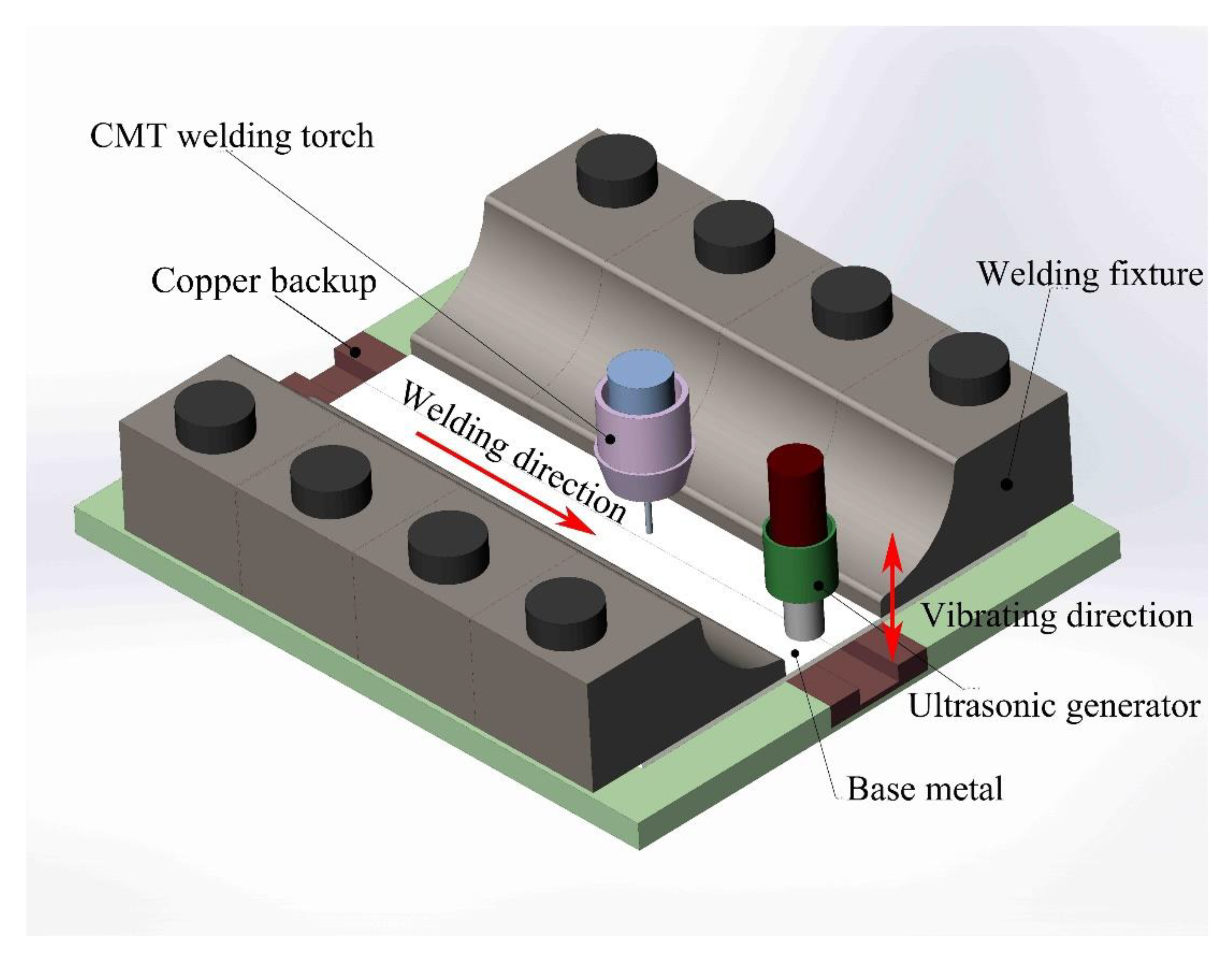
2. Materials and Methods

AISI 430 FSS plates with the dimensions of 250 mm × 100 mm × 1 mm was adopted as the base metal. The chemical constituents of the base metal and the ER 308L ASS wire (1.2 mm in diameter) which was selected as filler metal are listed in Table 1.
Figure 1 shows the schematic of ultrasonic-vibration-assisted CMT welding. The welding power source consists of a Fronius CMT Advanced 4000R system. The welding path and welding speed were controlled by utilizing a 6-axis robot (MOTOMAN HP6). Two sets of experiments (i.e., with and without ultrasonic vibration) were carried out to determine the influence of ultrasonic vibration on the microstructure and pitting corrosion resistance of the welded joints. Ultrasonic vibration was applied at a fixed position throughout the welding process. The welding speed, wire-feed speed and flow rate of the shielding gas consisting of 97.5% Ar and 2.5% CO2 were 60 cm/min, 3.8 m/min and 15 L/min, respectively. The ultrasonic generator with an output amplitude of 100 μm had an output power of 1500 W when the frequency was fixed at 20 kHz. The ultrasonic generator at the center of the weld is 10 mm away from the edge of the sheet.
Cross-sectional samples for microstructural examination were cut and prepared in accordance with the standard metallographic method. The samples were etched for 15 s in the etching agent (5 g FeCl3, 10 mL HCl and 20 mL H2O). The samples for immersion pitting corrosion and electrochemical pitting corrosion testing were grounded from 280 to 3000 grit SiC papers and then polished with 2.5 μm diamond paste, washed with ethanol and dried in hot air before tests.
Microstructures of the welded joints were observed by using an Axio Vert.A1 optical microscope (OM) (Carl Zeiss, Gottingen, Germany) and a Smartzoom5 3D digital microscope (Carl Zeiss, Gottingen, Germany). The higher-resolution micrographs were obtained through a JSM-7800F scanning electron microscope (SEM) (JEOL, Akishima, Japan) with an energy dispersive spectrometer (EDS). A D8 ADVANCE X-ray diffractometer (XRD) (Bruker, Karlsruhe, Germany) was used to conduct the phase-identification analysis.
A FMP30 ferrite detector was employed for measuring the ferrite content in the WM. Twenty points with an interval of 0.5 mm between adjacent points in the middle line of longitudinal section of the WM were selected, and the average value of these 20 points was taken as the final value.
Immersion pitting-corrosion testing was carried out in accordance with GB/T 17897-2016 standard (2016) [22]. The WM was located at the center of the samples, and the dimensions were approximately 30 mm × 20 mm × 1 mm. Then 100 g of analytically pure ferric chloride (FeCl3·6H2O) was dissolved in 900 mL deionized water to prepare 6% ferric chloride solution. The samples were submerged in the solution for 72 h at a temperature of 22 ± 1 °C. The pitting resistance of samples is expressed in terms of corrosion rate (K), i.e., weight loss per unit area and time. The average corrosion rate was obtained by three repetitions. The average corrosion rate was obtained by three repetitions. The corrosion rate was calculated as follows:
K = (W1W2)/(t × S)
where W1, W2, S and t represent the sample mass before the testing, sample mass after the testing, sample surface area and testing time, respectively.
Electrochemical pitting-corrosion testing was carried out in 1 M sodium chloride aqueous solution at room temperature via the potentiodynamic method according to ISO 15158 Standard (2014) [23] by using a ZJ-100 electrochemical testing system. The testing was conducted by utilizing a three-electrode electrochemical cell composed of a saturated calomel electrode (SCE) and a platinum mesh, which worked as a reference electrode and a counter electrode, respectively. When a stable corrosion potential (Ecorr) was constituted, the anodic curves were recorded at a 10 mV/min potential sweeping rate. The pitting potential (Epit) was ascertained based on the recorded polarization curves. The pitting potential (Epit) and the pitting-and-corrosion-potential difference (Epit − Ecorr) were used as the indexes for the pitting corrosion resistance of the FSS joints [24].

3. Results and Discussion
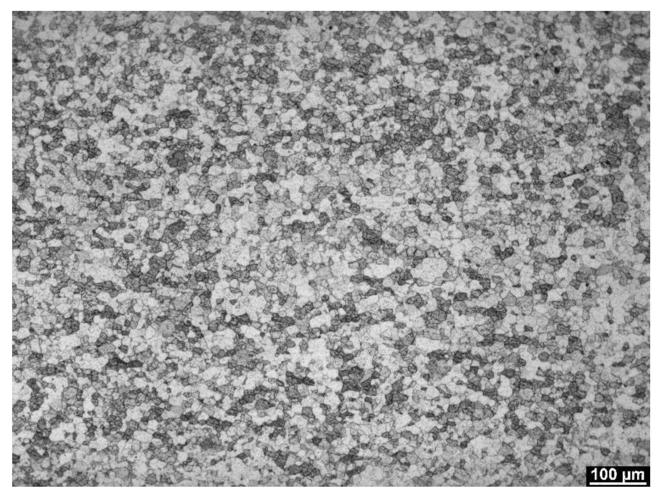
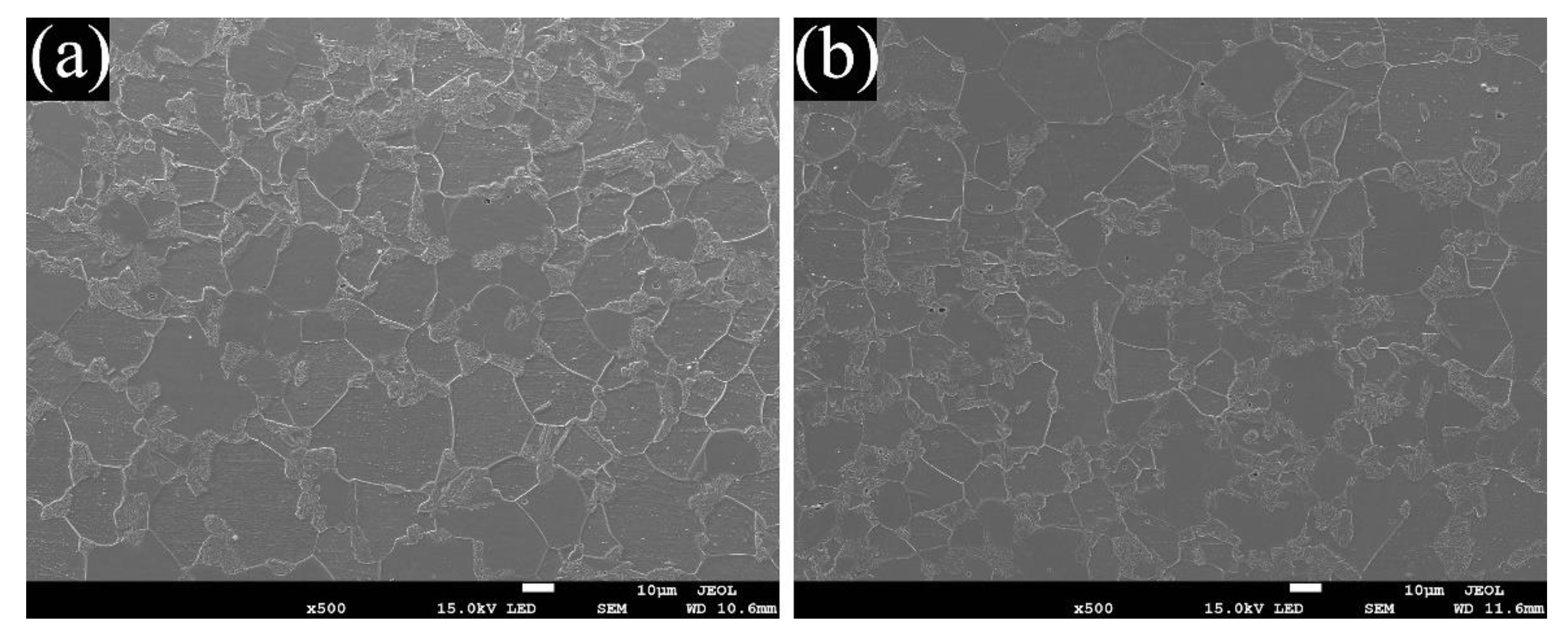
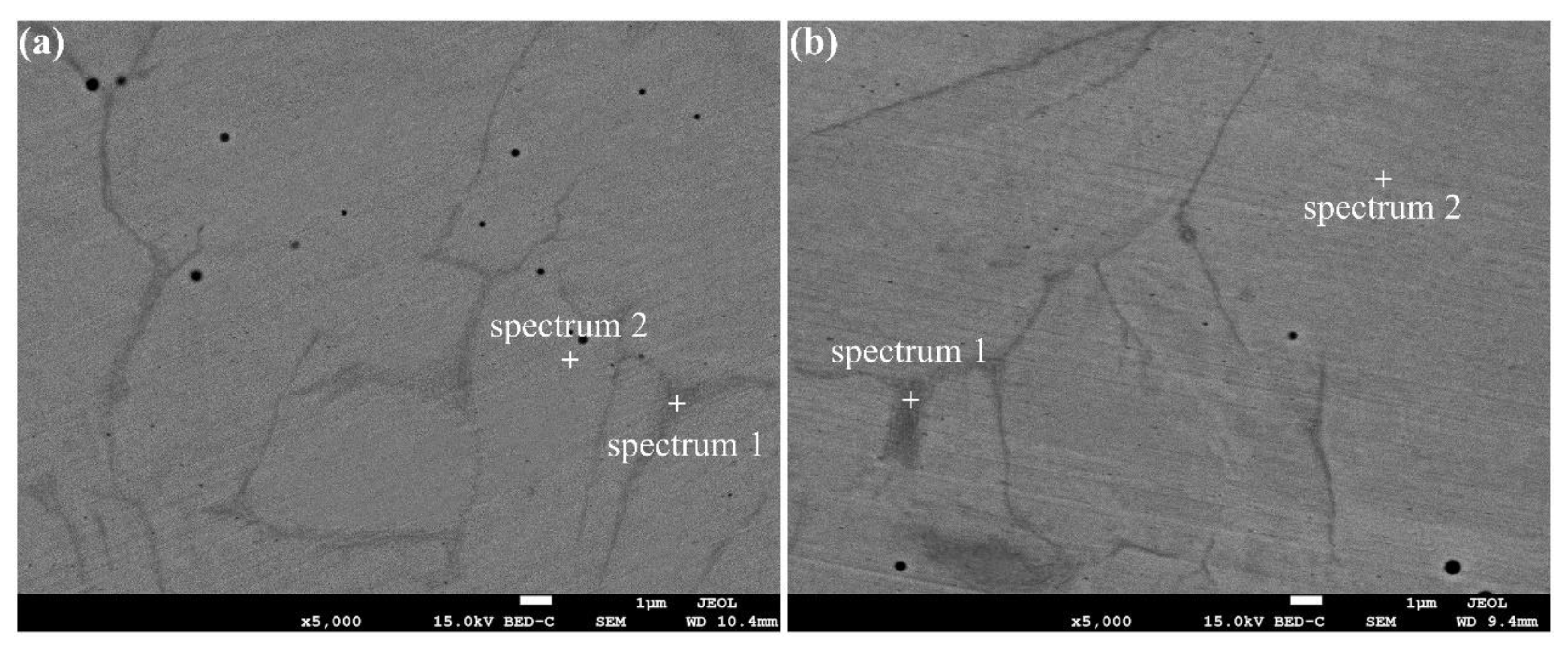
3.1. Microstructure

According to Figure 2, the base metal was composed of the equiaxed ferrite grains. The XRD pattern, as shown in Figure 3, proves that the base metal only has a single phase of ferrite.
As illustrated in Figure 4 and Figure 5, the resultant microstructure in the WM consisting of austenite (γ) and ferrite (α) was obtained because of the fusion and mixing of the ferritic base metal and austenitic filler metal, which can be proved by the XRD pattern, as shown in Figure 6. As noticed by Lippold and Kotecki [25], the ferrite and austenite dual-phase structure is the typical weld microstructure formed by FA solidification mode, and the transformation path of FA solidification mode can be obtained from the pseudo-binary phase diagram. The FA solidification mode can be expressed as L→L + F→L + F + (F + A)→F + A, where ‘L’, ‘F’ and ‘A’ represent liquid, ferrite and austenite, respectively. In this solidification mode, the ferrite phase was precipitated first in the initial period of solidification, and then some austenites were formed at the boundaries of ferrite grains through peritectic–eutectic reaction during the last stage of solidification. When the temperature of the WM dropped to the ferrite–austenite dual-phase zone, the stability of ferrite deteriorated gradually to some extent and transformed into austenite through the diffusion-controlled reaction, and the secondary austenite grains nucleated and grew at the grain boundaries of the primary ferrite. The ferritic elements in the residual ferrite enriched step by step as the phase transition continuously went on, while the austenitic elements were exhausted gradually. The diffusion was then restricted, and the ferrite became stable when the temperature dropped to a certain level. Thereby, the WM consisted of ferrite and austenite. The lath-shaped ferrite cut across the primary dendrite, and the austenite was distributed along the boundaries of the primary dendrite grains.
As presented in Figure 4, the primary ferrite grain in the WM underwent an obvious refinement from coarse columnar grain to fine equiaxed grain after introducing ultrasonic vibration. Under the effects of cavitation and acoustic streaming induced by ultrasonic vibration, a strong convection occurred in the molten pool, which could break up a large number of primary ferrite grains. At the same time, a large number of heterogeneous nucleation sites were formed in the shattered grains, promoting the heterogeneous nucleation and formation of refined grains. In addition, the convection occurring in the molten pool could make the high-temperature liquid metal flow from the upper part to the bottom, so that the temperature of the whole molten pool tends to be the same [26]. As a result, the central part of the molten pool was more conducive to nucleating and growing of equiaxed grains, and the microstructure of the molten pool changed from the coarse columnar grains to fine dendrites or equiaxed grains. Moreover, the tiny bubbles in the molten pool could vibrate, grow and accumulate the energy of acoustic field under the action of cavitation caused by ultrasonic vibration. When the accumulated energy reached the tolerance of bubbles, the cavitation bubbles would collapse and close sharply. During this period, huge energy was released, producing a micro-jet with strong impact, which could break the grains into several small pieces and further refined the grains [26].
As mentioned above, the secondary austenite grains nucleated and grew at the boundaries of the primary ferrite grains. Because the primary ferrite grains were obviously broken up by ultrasonic vibration, the number of grain boundaries of the primary ferrite grains could increase greatly, which greatly promoted the formation of austenite. To verify this analysis, the Fischer FMP30 ferrite detector was employed to detect the ferrite content in the WM, and the results are shown in Table 2.
According to Table 2, the ferrite content in the WM of the sample subjected to ultrasonic vibration reduced by ~45%. It should be noted that the standard deviation of the sample subjected to ultrasonic vibration also decreased. Because the strong convection in the molten pool caused by ultrasonic vibration resulted in a more uniform distribution of ferritic and austenitic elements, the ferritic and austenitic phase distributed evenly in the WM.
The microstructure of HAZ includes the area between the WM and base metal, and it is shown in Figure 7. It is obvious that the HAZ contained a coarse-grain zone and fine-grain zone, and some martensites existed in the HAZ. As reported by Khorrami et al. [27], the occurrence of martensite in the HAZ of FSS joints is a common phenomenon.
The optical microstructure of the coarse-grain zone in the HAZ is illustrated in Figure 8. The coarse-grain zone was further observed by using SEM, and the images are presented in Figure 9. The ferrite grain size increased significantly in comparison to that in the base metal because of the experience of high temperature in this zone. When the temperature was high enough, the austenite transformed into a continuous intergranular martensite layer and distributed at the ferrite grain boundaries in a network shape, and a small number of intragranular martensites showed isolated grains or strips distributed in the ferrite grains. In addition, there were granular precipitates in the ferrite grains. As reported by Lippold and Kotecki [25], these precipitates were carbides, nitrides or carbonitrides, and they were formed by supersaturated carbon and nitrogen in the ferrite phase because of the sharp decrease in the dissolubility of carbon and nitrogen when the temperature went down. Warmelo et al. [28] indicated that the precipitates mentioned above were generally formed in the HAZ of FSS joints.
As shown in Figure 10 and Figure 11, compared to that of the coarse-grain zone, the average grain size of the fine-grain zone of HAZ was smaller and was almost the same as that of the base metal. The content of martensite was dramatically reduced in this zone, and the martensite started to distribute dispersedly at the grain boundary instead of forming a network in the zone. The reason was that the fine-grain zone was remote from the weld center and, hence, the temperature was comparatively low, which inhibited the formation of high-temperature austenite to some extent and therefore prevented the transformation from high-temperature austenite to martensite. In addition, intragranular precipitates did not form in the grains, due to the relatively low temperature.
Figure 12 illustrates the SEM micrographs of the WM with backscattered electron (BE). The element compositions of the ferritic phase (the dark fields in Figure 12) and austenitic phase (the bright fields in Figure 12) were determined by using the EDS analysis, and the results are shown in Table 3.
As shown in Table 3, after introducing the ultrasonic vibration, the Cr content of the ferritic phase in the WM decreased, and that of the austenitic phase showed the opposite trend. There are two main reasons for this phenomenon. Firstly, the application of ultrasonic vibration led to a significant decline in the Cr-rich ferrite phase, which inevitably resulted in an obvious decrease in the segregation of Cr element, and the Cr content in austenite was bound to increase [24]. Secondly, the application of ultrasonic vibration caused strong convection in the molten pool, which also led to the homogenization of the element distribution [9].
The transition zone between the WM and HAZ would be a weak area owing to the large difference in chemical constituents between the filler metal and base metal. The property mismatch between the WM and base metal will worsen the property of welded joints [9]. As Ni is an austenitized element, the effect of ultrasonic vibration on Ni content in the transition zone was further studied. As shown in Figure 13, the width of the transition zone was increased from 13.78 to 22.06 μm by introducing the ultrasonic vibration. The acoustic streaming and cavitation induced by ultrasonic vibration enhanced the molten convention, leading to the acceleration of the element diffusion rate between the WM and HAZ; therefore, the width of the transition zone was increased. To some extent, the increase in the width of the transition zone can reduce the mismatch between the WM and base metal [9].

3.2. Pitting Corrosion Resistance

3.2.1. Immersion Pitting-Corrosion Resistance

As shown in Table 4, the corrosion rate of the welded joints was slightly higher in comparison to the base metal irrespective of whether the ultrasonic vibration was applied. The main reasons are as follows. Firstly, a large number of Cr-rich carbides were precipitated in the HAZ, leading to the decrease of Cr content and thus reducing the corrosion resistance of the joints. In addition, the WM was composed of the ferrite and austenite, and pitting corrosion tended to occur at the boundaries between austenite and ferrite phases [24], which also lead to the decline of corrosion resistance.
The corrosion rate of the welded joints decreased slightly after ultrasonic vibration was applied, indicating the enhancement in the pitting resistance of the welded joints. As aforementioned, after introducing the ultrasonic vibration, the austenite content of the WM increased significantly, and the segregation of Cr elements decreased, which played an active part in enhancing the pitting resistance of the welded joints. In addition, the narrow transition zone represented a short distance between the WM and HAZ with a great alloying element difference, which would lead to the formation of strong corrosive galvanic cells, and thus weakening the corrosion resistance of the welded joints. The application of ultrasonic vibration significantly increased the width of the transition zone between the WM and HAZ, therefore improving the corrosion resistance of the welded joints.

3.2.2. Electrochemical Pitting Corrosion Behavior

As mentioned above, the application of ultrasonic vibration resulted in a significant change in the microstructure of the WM. The electrochemical pitting test of the WM was carried out to investigate the effect of the microstructure variation on the pitting resistance of the WM, and the results are presented in Figure 14. Table 5 shows the values of the pitting-corrosion indexes for the WM and base metal. The values of Epit and Epit − Ecoor for the WM with ultrasonic vibration are significantly higher than that for both the WM without ultrasonic vibration and base metal. Moreover, the value of Epit for the WM without ultrasonic vibration is smaller than that for the base metal, while the value of Epit − Ecoor was close to that for base metal.
Because the boundary between austenite phase and ferritic phase is prone to form corrosion micro cell, resulting in a decrease of pitting resistance, the pitting resistance of the WM without ultrasonic vibration is worse than that of the base metal. However, on the other hand, the application of ultrasonic vibration could significantly reduce the content of ferrite phase in the WM, as illustrated in Table 2, so the number of boundary between ferrite and austenite phases was significantly reduced, resulting in an enhancement in the pitting-corrosion resistance of the WM. In addition, the application of ultrasonic vibration led to the decrease and increase in the Cr content in the ferrite and austenite phase in the WM, respectively, which also played an active part in enhancing the corrosion resistance of the WM [24]. Therefore, the pitting resistance of WM was significantly improved. In addition, the pitting corrosion occurred mostly at the ferrite phase adjacent to the austenite phase and propagated into the ferrite phase, according to Ha et al. [29]. It is because the atoms at the interface between the ferrite and austenite have higher energy than those in the matrix, and they easily react with Cl ions in the solution to form the corrosion pits firstly [30].

4. Conclusions

The microstructure and pitting-corrosion resistance of AISI 430 FSS joints fabricated by ultrasonic-vibration-assisted CMT welding with ER308L ASS as filler metal were investigated. The main conclusions of this study are summarized as follows.
(1)
The application of ultrasonic vibration could significantly refine the primary ferrite grains of the WM during the solidification process and increase the number of grain boundary of the primary ferrite grains, affecting the subsequent solid-phase transition process, and therefore significantly decreasing the ferrite content of the WM by about 45%.
(2)
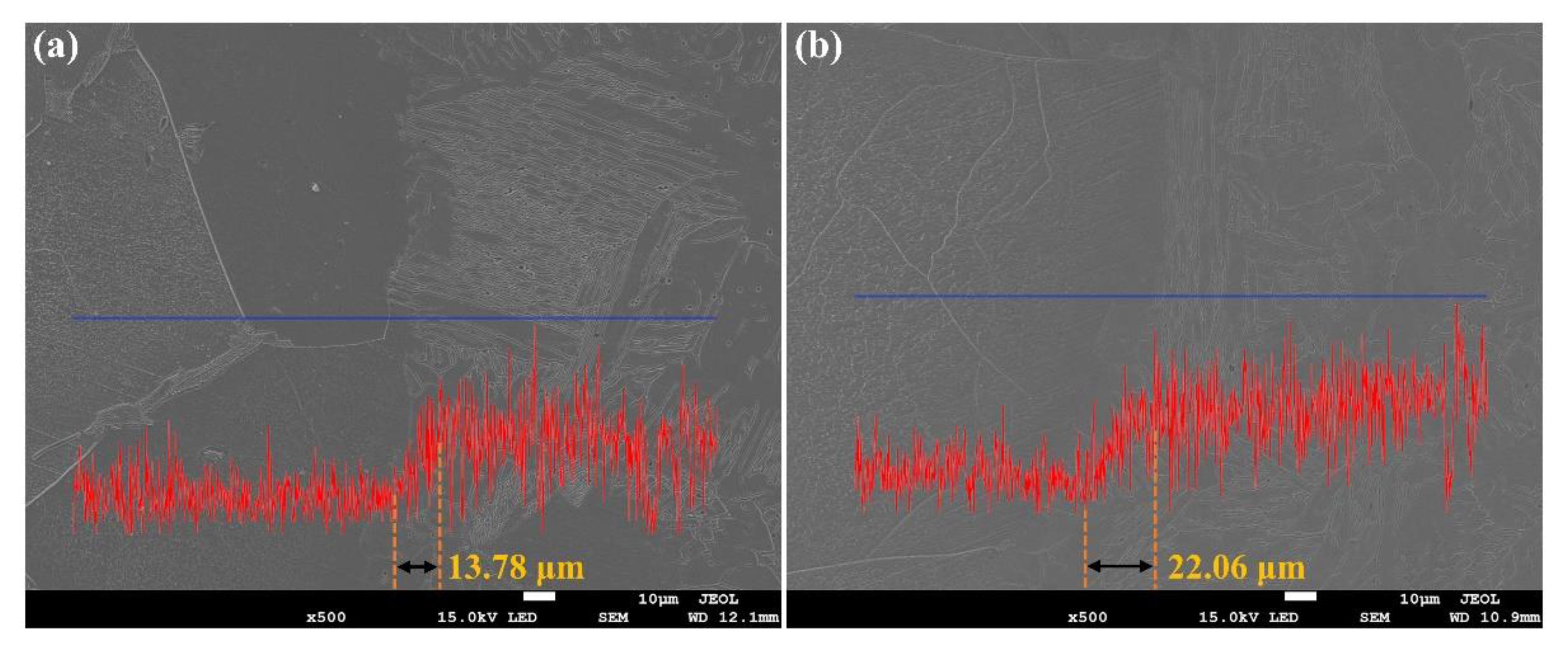
Introducing ultrasonic vibration could improve the uniformity of alloying elements in the WM and widen the transition zone between the WM and HAZ.
(3)
When the ultrasonic vibration was applied, the molten pool convection induced by the acoustic streaming effect, and the microjet induced by the cavitation effect led to the significant refinement of the primary ferrite grains and the homogenization of alloying elements in the WM.
(4)
Owing to the application of ultrasonic vibration, the austenite content in the WM increased, alloying elements in the WM tended to be homogenized and the width of the transition zone between the WM and HAZ increased, resulting in the improvement of pitting resistance of both the WM and welded joint.

Author Contributions

Conceptualization, J.S. and S.H.; methodology, N.X. and J.Z.; formal analysis, N.X. and J.Z.; writing—original draft preparation, N.X. and J.Z.; writing—review and editing, J.S.; supervision, S.H. All authors have read and agreed to the published version of the manuscript.

Funding

This research was funded by National Natural Science Foundation of China (Grant No. 52075377) and Tianjin Research Program of Application Foundation and Advanced Technology (Grant No. 15JCZDJC38600).

Institutional Review Board Statement

Not applicable.

Informed Consent Statement

Not applicable.

Data Availability Statement

The data presented in this study are available on request from the corresponding author.

Acknowledgments

The authors express their gratitude Bi J and Zhen Y.H. for kind help with experiment.

Conflicts of Interest

The authors declare no conflict of interest.

References

  1. Gurram, M.; Adepu, K.; Pinninti, R.R.; Gankidi, M.R. Effect of copper and aluminium addition on mechanical properties and corrosion behaviour of AISI 430 ferritic stainless steel gas tungsten arc welds. J. Mater. Res. Technol. 2013, 2, 238–249. [Google Scholar] [CrossRef] [Green Version]
  2. Han, J.; Li, H.; Zhu, Z.; Jiang, L.; Xu, H.; Ma, L. Effects of processing optimisation on microstructure, texture, grain boundary and mechanical properties of Fe-17Cr ferritic stainless steel thick plates. Mater. Sci. Eng. A 2014, 616, 20–28. [Google Scholar] [CrossRef]
  3. Fujita, N.; Ohmura, K.; Yamamoto, A. Changes of microstructures and high temperature properties during high temperature service of Niobium added ferritic stainless steels. Mater. Sci. Eng. A 2003, 51, 272–281. [Google Scholar] [CrossRef]
  4. Fu, J.; Li, F.; Sun, J.; Cui, K.; Du, X.; Wu, Y. Effect of crystallographic orientations on the corrosion resistance of Fe-17Cr ferritic stainless steel. J. Electroanal. Chem. 2019, 841, 56–62. [Google Scholar] [CrossRef]
  5. Abdallah, M. Corrosion behaviour of 304 stainless steel in sulphuric acid solutions and its inhibition by some substituted pyrazolones. Mater. Chem. Phys. 2003, 82, 786–792. [Google Scholar] [CrossRef]
  6. Loto, R.T.; Loto, C.A. Corrosion behaviour of S43035 ferritic stainless steel in hot sulphate/chloride solution. J. Mater. Res. Technol. 2018, 7, 231–239. [Google Scholar] [CrossRef]
  7. The International Nickel Company. Corrosion Resistance of Austentic Stainless Steels in Chemical Environments; The International Nickel Company, Inc.: Toronto, ON, Canada, 1963. [Google Scholar]
  8. Lippold, J.C. Welding Metallurgy and Weldability; Wiley Online Library: Hobeken, NJ, USA, 2015. [Google Scholar]
  9. Zhou, S.; Ma, G.; Wu, D.; Chai, D.; Lei, M. Ultrasonic vibration assisted laser welding of nickel-based alloy and austenite stainless steel. J. Manuf. Process. 2018, 31, 759–767. [Google Scholar] [CrossRef]
  10. Grubb, J.F. Austenitic and feritic stainless steels. In Uhlig’s Corrosion Handbook, 3rd ed.; Revie, R.W., Ed.; John Wiley & Sons: Hoboken, NJ, USA, 2011. [Google Scholar]
  11. Davis, J.R. Corrosion of Weldments; ASM International: Materials Park, OH, USA, 2006; pp. 43–75. [Google Scholar]
  12. Furukawa, K. New CMT arc welding process—Welding of steel to aluminium dissimilar metals and welding of super-thin aluminium sheets. Weld. Int. 2006, 20, 440–445. [Google Scholar] [CrossRef]
  13. Feng, J.; Zhang, H.; He, P. The CMT short-circuiting metal transfer process and its use in thin aluminium sheets welding. Mater. Des. 2009, 30, 1850–1852. [Google Scholar] [CrossRef]
  14. Hu, S.; Zhang, H.; Wang, Z.; Liang, Y.; Liu, Y. The arc characteristics of cold metal transfer welding with AZ31 magnesium alloy wire. J. Manuf. Process. 2016, 24, 298–306. [Google Scholar] [CrossRef]
  15. Mohandas, T.; Reddy, G.M.; Naveed, M. Comparative evaluation of gas tungsten and shielded metal arc welds of a “ferritic” stainless steel. J. Mater. Process. Technol. 1999, 94, 133–140. [Google Scholar] [CrossRef]
  16. Xie, W.; Fan, C.; Yang, C.; Lin, S. Effect of acoustic field parameters on arc acoustic binding during ultrasonic wave-assisted arc welding. Ultrason. Sonochem. 2016, 29, 476–484. [Google Scholar] [CrossRef] [PubMed]
  17. Dai, W.L. Effects of high-intensity ultrasonic-wave emission on the weldability of aluminum alloy 7075-T6. Mater. Lett. 2003, 57, 2447–2454. [Google Scholar] [CrossRef]
  18. Cui, Y.; Xu, C.; Han, Q. Effect of ultrasonic vibration on unmixed zone formation. Scr. Mater. 2006, 55, 975–978. [Google Scholar] [CrossRef]
  19. Sun, Q.; Lin, S.; Yang, C.; Zhao, G. Penetration increase of AISI 304 using ultrasonic assisted tungsten inert gas welding. Sci. Technol. Weld. Join. 2009, 14, 765–767. [Google Scholar] [CrossRef]
  20. Yuan, T.; Kou, S.; Luo, Z. Grain refining by ultrasonic stirring of the weld pool. Acta Mater. 2016, 106, 144–154. [Google Scholar] [CrossRef] [Green Version]
  21. Irani, H.; Ghazani, M.S. Effect of grain refinement on tensile properties and electrochemical behavior of Fe-18.5%Cr ferritic stainless steel. Mater. Chem. Phys. 2020, 251, 123089. [Google Scholar] [CrossRef]
  22. GB/T 17897-2016; Corrosion of Metals and Alloys—Corrosion Test for Pitting Corrosion Resistance of Stainless Steels in the Ferric Chloride Solution. Standardization Administration of China: Beijing, China, 2016.
  23. ISO 15158:2014; Corrosion of Metals and Alloys—Method of Measuring the Pitting Potential for Stainless Steels by Potentiodynamic Control in Sodium Chloride Solution. International Organization for Standardization: Geneva, Switzerland, 2014.
  24. Jegdić, B.; Bobić, B.; Radojković, B.; Alić, B.; Radovanović, L. Corrosion resistance of welded joints of X5CrNi18-10 stainless steel. J. Mater. Process. Technol. 2019, 266, 579–587. [Google Scholar] [CrossRef]
  25. Lippold, J.C.; Kotecki, D.J. Welding Metallurgy and Weldability of Stainless Steel; John Wiley & Sons: Hoboken, NJ, USA, 2005. [Google Scholar]
  26. Fan, Y.; Sun, Q.; Yang, C.; Lin, S. TIG welding of 304 stainless steel based on ultrasonic vibration. Trans. China. Weld. Inst. 2009, 30, 91–94. [Google Scholar]
  27. Khorrami, M.S.; Mostafaei, M.A.; Pouraliakbar, H.; Kokabi, A.H. Study on microstructure and mechanical characteristics of low-carbon steel and ferritic stainless steel joints. Mater. Sci. Eng. A 2014, 608, 35–45. [Google Scholar] [CrossRef]
  28. Van, W.M.; Nolan, D.; Norrish, J. Mitigation of sensitisation effects in unstabilised 12% Cr ferritic stainless steel welds. Mater. Sci. Eng. A 2007, 464, 157–169. [Google Scholar]
  29. Ha, H.Y.; Jang, M.H.; Lee, T.H.; Moon, J. Interpretation of the relation between ferrite fraction and pitting corrosion resistance of commercial 2205 duplex stainless steel. Corros. Sci. 2014, 89, 154–162. [Google Scholar] [CrossRef]
  30. Chen, Y.F.; Yang, B.; Zhou, Y.T.; Wu, Y.; Zhu, H.H. Evaluation of pitting corrosion in duplex stainless steel Fe20Cr9Ni for nuclear power application. Acta. Mater. 2020, 197, 172–183. [Google Scholar] [CrossRef]
Figure 1. Schematic of ultrasonic vibration-assisted CMT welding.
Metals 12 00382 g001
Figure 2. Microstructure of the base metal.
Metals 12 00382 g002
Figure 3. XRD pattern of the base metal.
Metals 12 00382 g003
Figure 4. Microstructure of the WM: (a,b) without ultrasonic treatment and (c,d) with ultrasonic treatment.
Metals 12 00382 g004
Figure 5. SEM images of the WM: (a) without ultrasonic treatment and (b) with ultrasonic treatment.
Metals 12 00382 g005
Figure 6. XRD pattern of the WM.
Metals 12 00382 g006
Figure 7. Microstructure of the HAZ: (a) without ultrasonic treatment and (b) with ultrasonic treatment.
Metals 12 00382 g007
Figure 8. Microstructure of the coarse-grain zone in the HAZ: (a) without ultrasonic treatment and (b) with ultrasonic treatment.
Metals 12 00382 g008
Figure 9. SEM image of the coarse-grain zone in the HAZ: (a) without ultrasonic treatment and (b) with ultrasonic treatment.
Metals 12 00382 g009
Figure 10. Microstructure of the fine-grain zone in the HAZ: (a) without ultrasonic treatment and (b) with ultrasonic treatment.
Metals 12 00382 g010
Figure 11. SEM images of the fine-grain zone in the HAZ: (a) without ultrasonic treatment and (b) with ultrasonic treatment.
Metals 12 00382 g011
Figure 12. Microstructure of the WM observed by SEM with backscattered electron signal and the locations of the EDS in the ferritic phase (Spectrum 1) and austenitic phase (Spectrum 2): (a) without ultrasonic treatment and (b) with ultrasonic treatment.
Metals 12 00382 g012
Figure 13. EDS linear scanning of the Ni element content in the transition zone between the WM and HAZ: (a) without ultrasonic treatment and (b) with ultrasonic treatment.
Metals 12 00382 g013
Figure 14. Polarization curve of the WM for all samples: (a) without ultrasonic treatment, (b) with ultrasonic treatment and (c) base metal.
Metals 12 00382 g014
Table 1. Chemical constituents of the base metal and filler metal (wt.%).
MaterialCSiMnPSCrNiMoCuFe
AISI 4300.050.290.350.0160.00216.270.13--Bal.
ER 308L0.0240.421.850.0190.0120.29.50.120.14Bal.
Table 2. Ferrite content in the WM.
Experimental ConditionsFerrite Content (%)Standard Deviation
Without ultrasonic treatment31.361.28
With ultrasonic treatment17.070.48
Table 3. EDS results of the ferritic phase and austenitic phase marked in Figure 12 (wt.%).
Experimental ConditionsSpectrumFeCrNiCSi
Without ultrasonic treatment Spectrum 171.4521.624.391.750.79
Spectrum 273.0118.456.161.680.71
With ultrasonic treatment Spectrum 172.0420.105.841.230.79
Spectrum 271.8019.187.121.210.68
Table 4. Results of the immersion pitting-corrosion testing for all samples.
Experimental ConditionsCorrosion Rate (g/(m2·h))Standard Deviation
Without ultrasonic treatment17.680.92
With ultrasonic treatment17.010.55
Base metal15.710.89
Table 5. Values of the pitting corrosion indexes of the WM for all samples.
Experimental ConditionsEcoor (mV)Epit (mV)Epit − Ecoor (mV)
Without ultrasonic treatment−16777244
With ultrasonic treatment−150187337
Base metal−120125245
Publisher’s Note: MDPI stays neutral with regard to jurisdictional claims in published maps and institutional affiliations.

