Communication

Fabrication of Precursor by Consolidating Aluminum Alloy Powder Using Friction Stir Welding and Its Foaming

Graduate School of Science and Technology, Gunma University, Kiryu 376-8515, Japan
*
Author to whom correspondence should be addressed.
Metals 2022, 12(2), 338; https://doi.org/10.3390/met12020338
Submission received: 18 January 2022 / Revised: 6 February 2022 / Accepted: 9 February 2022 / Published: 15 February 2022

Abstract

:
In this study, we fabricated a precursor by FSW using ADC12 (Al-Si-Cu alloy) powder and foamed the obtained precursor by optical heating to fabricate the porous aluminum (Al). If ADC12 powder can be used for fabricating the precursor, it is expected that Al waste materials from the manufacturing of industrial products, such as Al cutting scraps, can be used as recycled Al chips, with which the cost of porous Al manufacturing can be reduced. The results demonstrated that ADC12 powder can be consolidated as well as the blowing agent (titanium hydride) and stabilization agent (alumina) powders can be mixed into the consolidated ADC12 by FSW to fabricate precursors at the tool traversing speed v = 10–50 mm/min. In addition, the obtained precursor can be foamed by optical heating. It was also found that the precursor with fewer cracks and defects can be obtained at v = 10, 20, and 30 mm/min versus at v = 40 and 50 mm/min. As a result, porous Al with relatively good pore structures was obtained at v = 10–30 mm/min.

1. Introduction

Porous aluminum (Al) is expected to be used as a structural material for automobiles because it contains a large number of pores, is light enough to float on water, and has excellent shock-absorbing properties [1,2,3]. In recent years, friction stir welding (FSW) has come to be used for joining components of automobiles, railroad cars, and transportation equipment [4,5,6,7]. In the FSW, a rotating tool with a probe at its tip is plunged into Al plates and traversed, causing part of the Al plates softened by frictional heat to flow plastically.
Recently, the fabrication of porous Al using FSW has been attempted [8,9,10,11,12]. In this fabrication method, the blowing agent (titanium hydride) powder was first spread between the Al plates and laminated, as shown in Figure 1a. Then, as shown in Figure 1b, the tool was traversed over the area where the blowing agent is spread, and the blowing agent was uniformly distributed into the Al plates by plastic flow during FSW. Finally, as shown in Figure 1c, the stirred area was cut into the desired shape to obtain a precursor of porous Al. Porous Al can be fabricated by heating the precursor in an electric furnace to form foam. In addition, in our previous study, we have attempted to perform precursor fabrication and foaming in a single process using only FSW [13,14]. In this method, two Al plates with a blowing agent (titanium hydride) powder sandwiched between them were first inserted into grooves machined in the steel plate. Next, an upper tool was traversed over the laminated plates from above to fabricate a precursor by FSW of the Al plates, and a lower tool was traversed over the steel plate from below in the same process, and the precursor was foamed by the frictional heat generated between the lower tool and the steel plate. In this process, if waste materials from the manufacture of industrial products, such as Al cutting scraps [15,16], can be used as recycled Al chips instead of Al plates in the future, it is expected that the cost of porous Al will be reduced.
In this study, as a feasibility study, we attempted to investigate whether the precursors can be fabricated by changing a part of the Al plate to Al powder. The effect of the tool traversing speed on the consolidated Al powder for the fabricating precursor was investigated. The effect on foaming was also investigated by foaming the fabricated precursor using optical heating. Optical heating [17,18,19] was used because the foaming was affected by the traversing speed of the lower tool when the foaming was performed by the lower tool in the same process as the precursor fabrication.

2. Materials and Methods

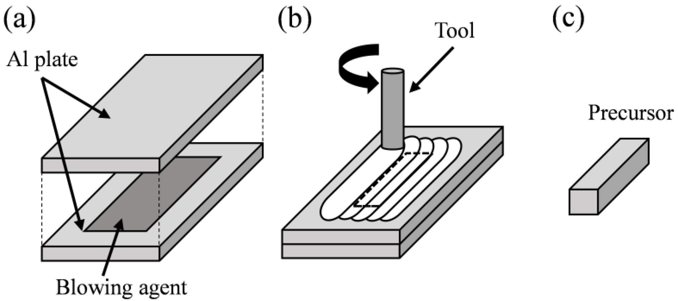
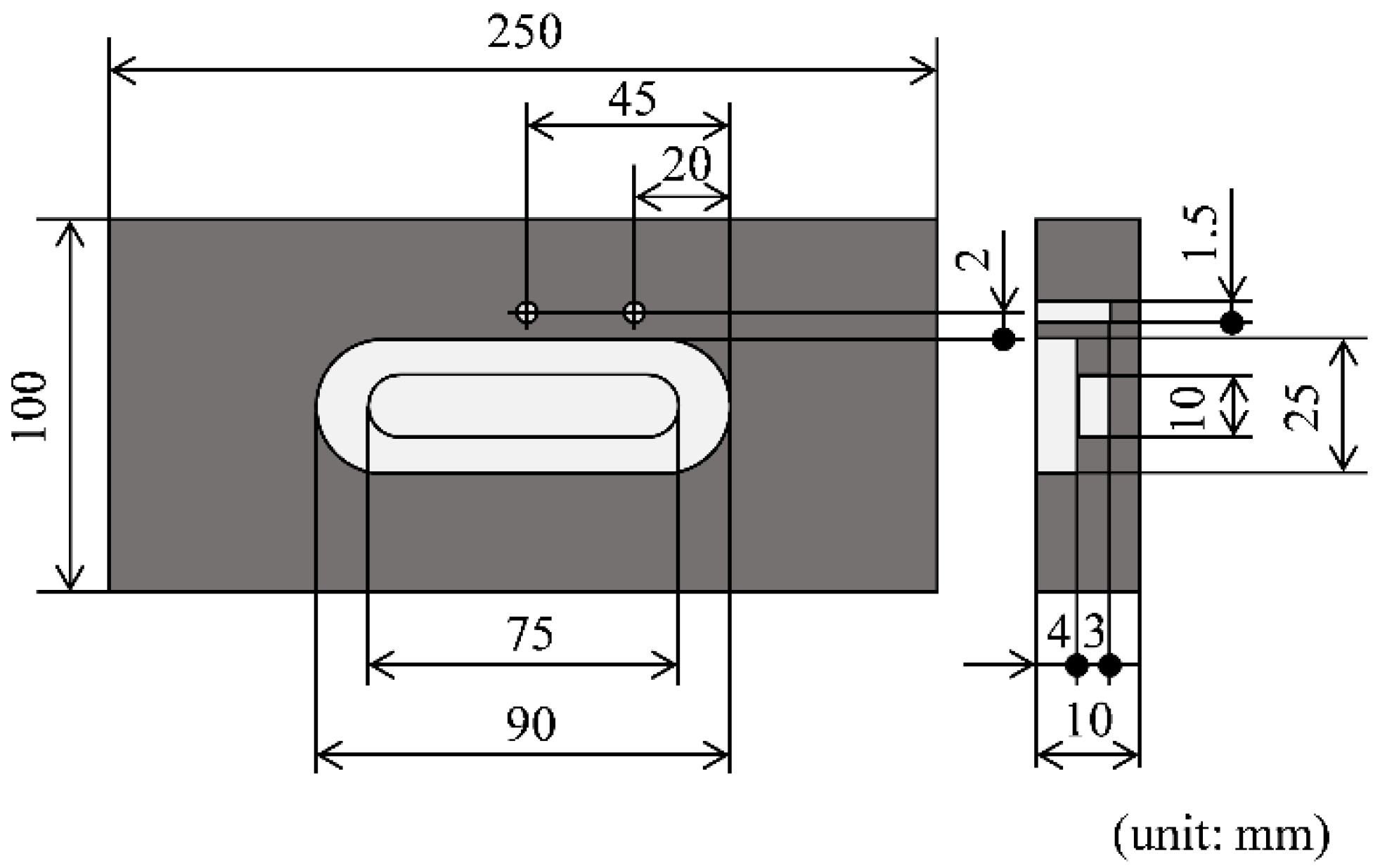
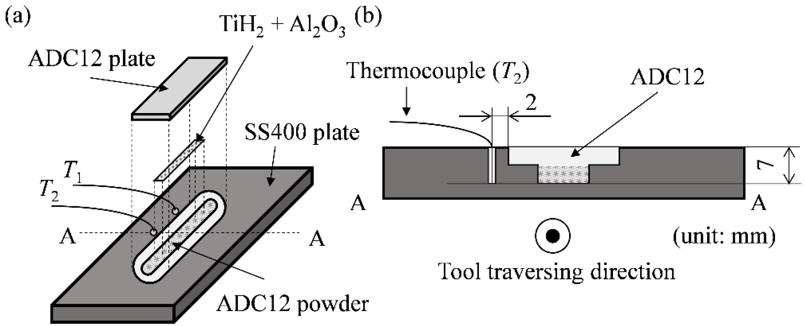
2.1. Fabrication of Precursor

As shown in Figure 2, a groove of 90 mm in length, 25 mm in width, and 4 mm in depth was first machined on a 250 mm × 100 mm × 10 mm SS400 steel plate using a milling machine. A further groove of 75 mm in length, 10 mm in width, and 3 mm in depth was machined in the center of the groove. In addition, two holes of 7 mm in depth and 1.5 mm in diameter, as the same depth as the bottom of the grooves, were drilled with a drilling machine at 20 mm from the right edge of the grooves and at the center of the grooves (45 mm), 2 mm away from the side of the groove.
ADC12 (Al-Si-Cu) alloy powder (Toyo Aluminium K.K., Osaka, Japan), as shown in the scanning electron microscope (SEM) image in Figure 3, and the ADC12 alloy sheet (3 mm thick) fabricated by die-casting, were used as the base material for porous Al. The ADC12 alloy sheet was cut to 25 mm × 70 mm × 3 mm using an electric discharge machine. Titanium hydride powder (TiH2, particle size less than 45 μm, Kojundo Chemical Lab. Co., Ltd., Sakado, Japan) was used as a blowing agent, and alumina powder (α-Al2O3, particle size approximately 1 μm, Kojundo Chemical Lab. Co., Ltd., Sakado, Japan) was used as a stabilization agent. The amount of these powders added was 1 mass% of TiH2 and 5 mass% of Al2O3, respectively, relative to the mass of the region where the ADC12 powder and the ADC12 plate were stirred by the probe of the FSW tool during the traversing tool.
Figure 4a shows the schematic of the setup of the powders and plate, and Figure 4b shows the cross section along A-A in Figure 4a. First, ADC12 powder was placed in the entire narrow groove of the steel plate, and then a mixture of TiH2 and Al2O3 powder was spread on top of the ADC12 powder. An ADC12 plate was then placed in the wide groove of the steel plate to cover it, and fixed at the FSW equipment. A K-type sheath thermocouple was inserted into the two holes, and the temperature was measured at the position 20 mm from the right edge of the groove in the traversing direction of the tool as T1 and at the position in the center of the groove as T2. The tip of each thermocouple was placed at the same height as the bottom surface of the lower groove. The data collection interval was 100 ms. FSW (Hitachi Setsubi Engineering Co., Ltd., Hitachi, Japan) was then performed to consolidate the ADC12 powder, and at the same time, blowing and stabilization agents were mixed into the consolidated ADC12 to fabricate precursors. The tool was made of tool steel with a shoulder diameter of 17 mm, a probe diameter of 5 mm, a probe length of 4.8 mm, and a threaded probe. The dimensions of the groove were selected such that the FSW tool can traverse without contacting the steel plate. The tool traversing conditions were a constant rotation speed of 1000 rpm and tilt angle of 3 degrees, and the traversing distance was 45 mm. The tool traversing speed v was set to 10, 20, 30, 40, and 50 mm/min, and the number of traversing time was 1 pass. This condition was selected because good foaming was observed at v = 30 mm/min and 1 pass in the simultaneous process in our previous study [14]. During the tool traversing, the ADC12 plate was observed with a video camera from an oblique upward direction.

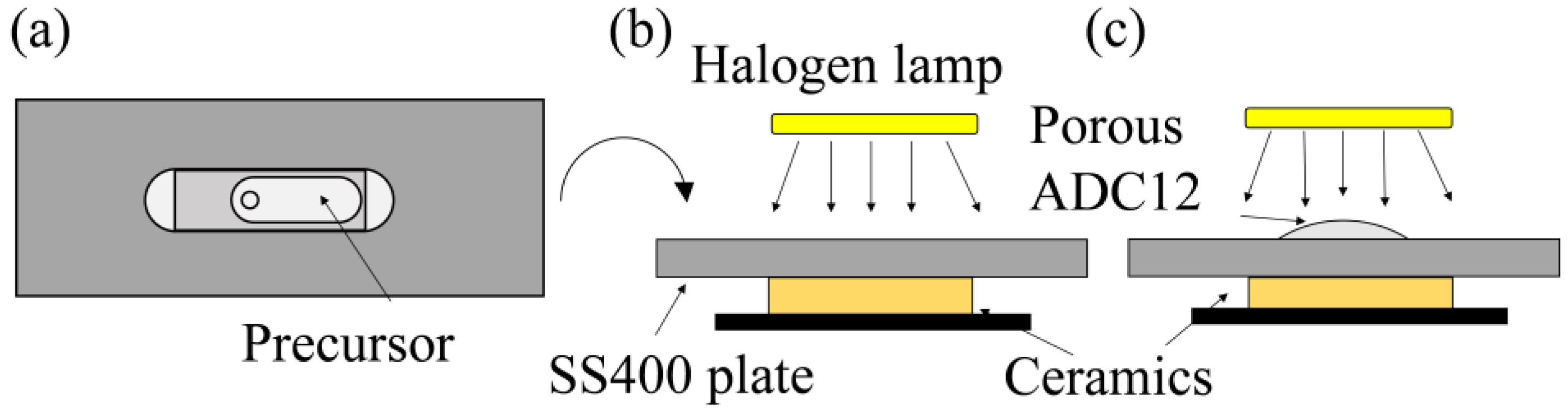
2.2. Foaming of Precursor by Optical Heating

Figure 5 shows the schematic of foaming process by optical heating. The fabricated precursor was placed on the ceramics honeycomb (Shinfuji Burner Co., Ltd., Toyokawa, Japan) and heated by three halogen lamps without being removed from the steel plate, as shown in Figure 5a,b. The power required for heating was 1620 W (9 A × 180 V) for each lamp. The distance between the halogen lamps and the top of the precursor was set to 40 mm. A K-type sheath thermocouple was inserted into the hole in the center of the groove of the steel plate used for precursor fabrication (position T2), and the temperature during foaming was measured. In addition, black guard spray (FC-153, Fine Chemical Japan Co., Ltd., Tokyo, Japan) was applied to the surface of the precursor to promote heat absorption. The halogen lamps were turned off when the precursor foamed and the temperature reached 670 °C, as shown in Figure 5c. Foaming time was between 6 and 6.5 min. The temperature of 670 °C was a sufficient temperature for foaming ADC12 precursor [18], because the liquidus temperature of ADC12 is 580 °C [20].

3. Results and Discussion

3.1. Fabrication of Precursor

Figure 6a–c show the tool traversing behavior at v = 10 mm/min. Figure 6a shows the start of tool traversing, Figure 6b shows when the tool passed through T2, and Figure 6c shows the end of tool traversing. The start of the tool traversing was defined as t = 0 s. As shown by the arrows in Figure 6b,c, cracks were observed at the start of tool traversing. Other traversing speeds demonstrated a similar tendency. However, it was observed that the generation of the cracks continued in the tool traversing direction at v = 40 and 50 mm/min, as described below. Figure 6d shows the temperature history at v = 10 mm/min. The solid and dashed lines indicate the temperatures of T1 and T2, respectively. (b) and (c), indicated by black arrows, correspond to the tool traversing behavior shown in Figure 6b,c. The solidus temperature of ADC12 is 515°C [20], indicating that the stirring was done in the solid state during FSW. In addition, it is known that the precursor begins to foam gradually above the solidus temperature, and foams significantly above the liquidus temperature [18], indicating that foaming has not yet occurred during FSW.

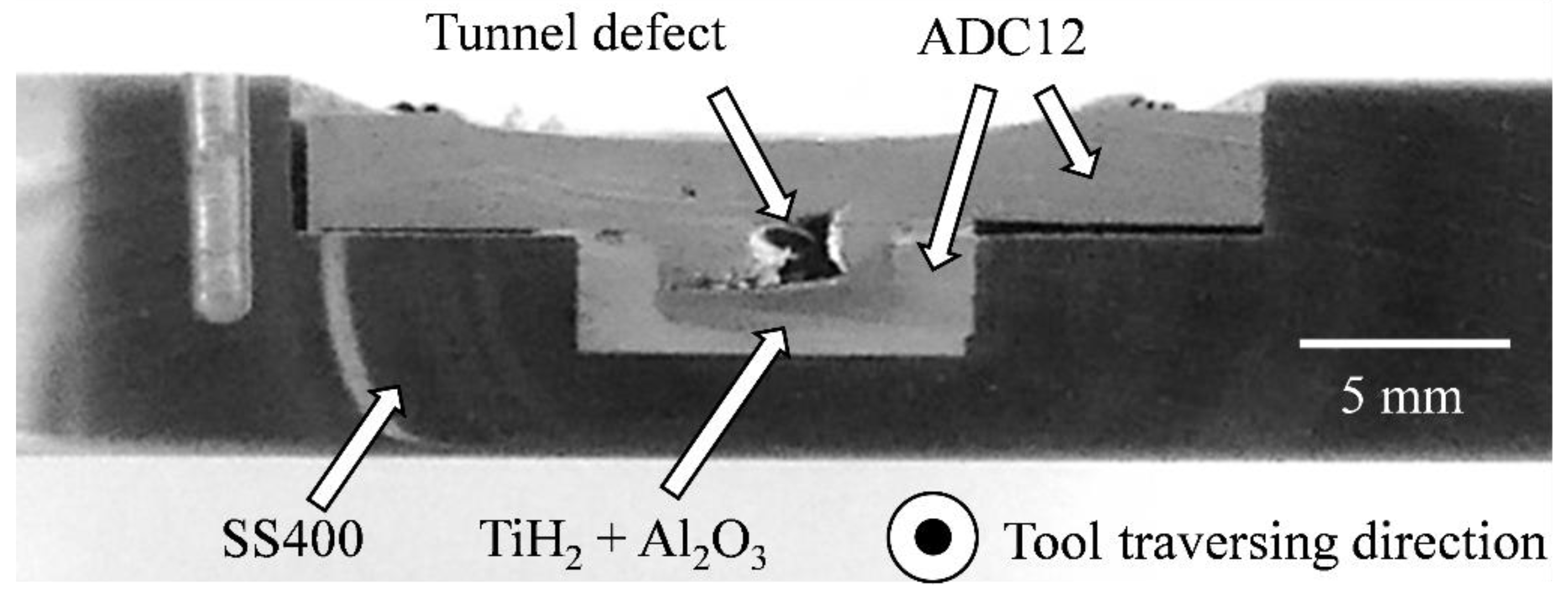
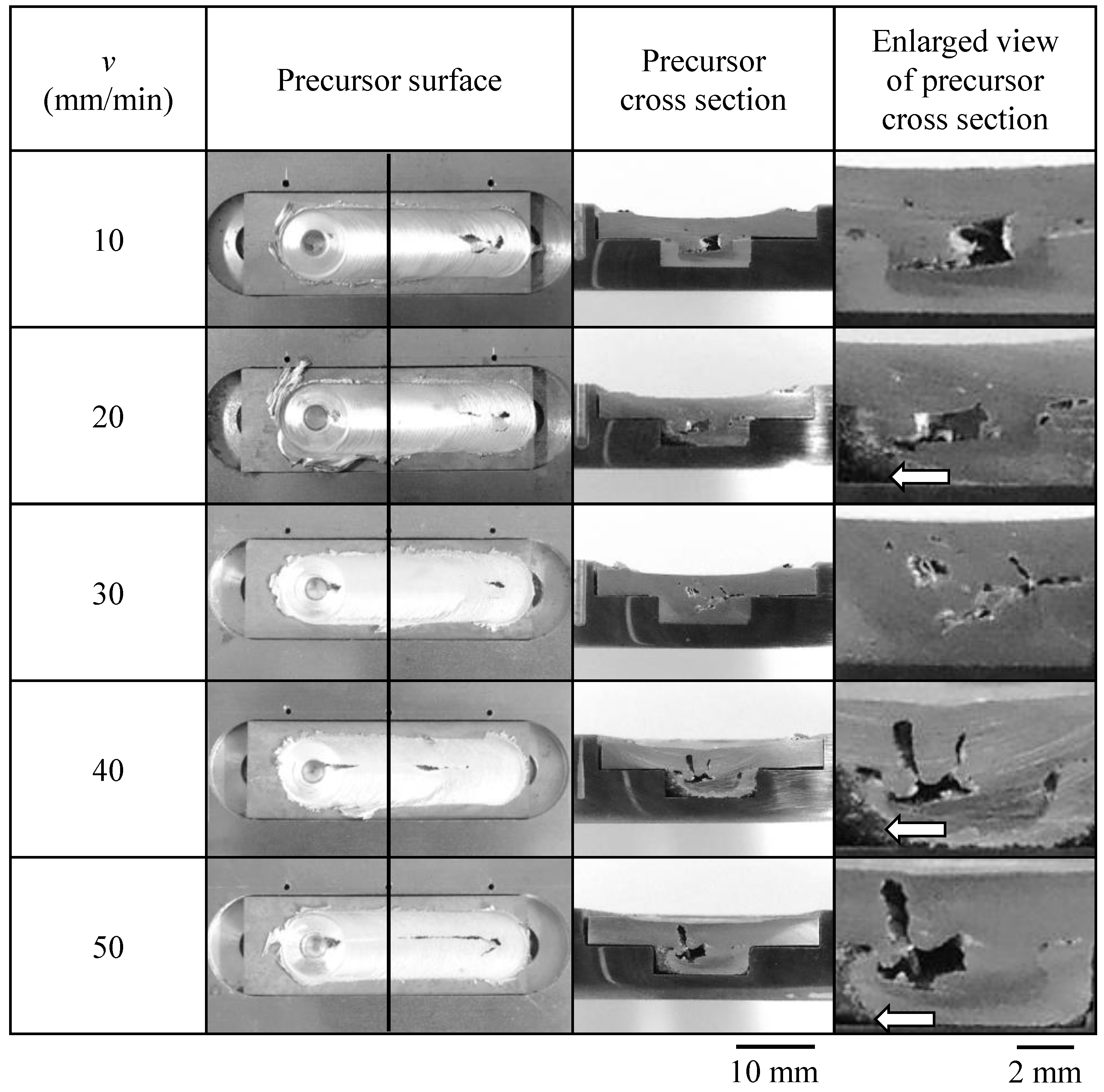
3.2. Observation of Surface and Cross Section of Precursor

Figure 7 shows the cross section of the precursor fabricated at v = 10 mm/min at the position of T2. In the cross section, the top of the precursor, is the surface where the tool was traversed, and the tool traversing direction is from the back to the front of the image. It can be observed that the ADC12 powder placed in the lower part of the groove was consolidated by tool traversing, and a dense precursor was obtained. However, tunnel defect was observed in the cross section. The dark gray area around the tunnel defect is the area where TiH2 and Al2O3 were distributed by stirring with the probe of the FSW tool. If the mixing of the TiH2 and Al2O3 was insufficient, the powders were inhomogeneously distributed and remained concentrated [8]. As no such concentration was observed, it was considered that TiH2 and Al2O3 dispersed throughout the dark gray area. The light gray area near the groove wall is where only the ADC12 powder was consolidated by frictional heat and the tool plunging load. As a result, it was found that both consolidation of the ADC12 powder and dispersion of the TiH2 and Al2O3 into ADC12 could be achieved where the probe passed through; that is, the precursor can be fabricated. This tendency was also observed for all other v.
Figure 8 shows photographs of the precursors fabricated at v = 10–50 mm/min, the cross sections at the solid line (position of T2), and magnified views of the stirred part of the cross section. The cross section of the precursor fabricated at v = 10 mm/min was the same sample as Figure 7. It can be observed that the ADC12 powder placed in the lower part of the groove was consolidated by tool traversing, and a dense precursor was obtained, regardless, with v. However, cracks were observed in the surface of the precursor, and tunnel defects were observed in the cross section. This could be attributed to the low filling ratio of the ADC12 powder, which was consolidated and densified by the stirring, resulting in a lack of material. The filling ratio of ADC12 powder in the lower part of the groove was approximately 50% because it was only placed in the groove. Here, the filling ratio is the ratio of the volume of ADC12 powder to the volume of the groove, which is calculated from the weight and density of the ADC12 powder. In addition, the ADC12 powder was pushed out from the gap between the groove and the ADC12 plate on top during the tool traversing. Therefore, the amount of ADC12 powder was insufficient and the density of ADC12 became low, resulting in a generation of defects by insufficient mixing. Some parts of the ADC12 powder were not consolidated as indicated by arrows, but these parts were not stirred by the tool. Furthermore, at v = 40 and 50 mm/min, the FSW conditions were not appropriate and cracks on the precursor surface and tunnel defects became more obvious.

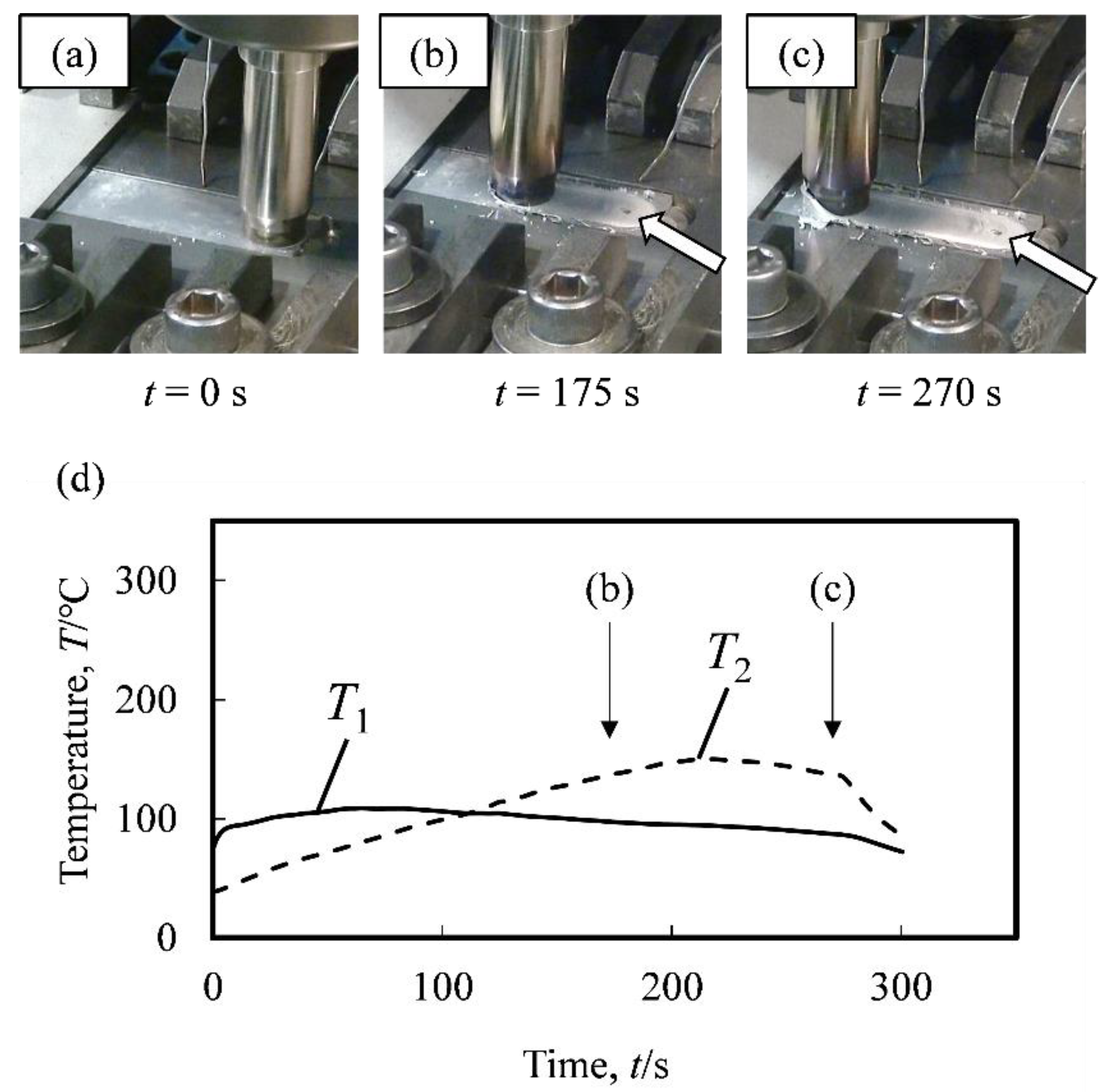
3.3. Foaming of Precursor by Optical Heating

Figure 9 shows the porous Al fabricated by foaming the precursor fabricated at v = 10–50 mm/min and their cross sections at the black solid lines (position of T2). The photographs of the porous Al were taken from the side direction of the steel plate, and the traversing direction of the tool was from right to left, with foaming upward. In the area indicated by the black arrows, cracks were generated at the surface during FSW, and some foaming defects occurred due to insufficient stirring and gas loss during foaming. However, other parts were foamed, and many pores can be observed in the cross sections. The tool traversing direction in the cross section was from the back to the front of the images. Tunnel defects were observed at the precursors, as shown in Figure 8, but the internal defects were indistinguishable from pores after foaming. Note that, as indicated in Figure 7, not all ADC12 parts are stirred and some parts do not contain the blowing agent. The pores are widened to some extent by the foaming force of heating, but there are still dense areas. At v = 40 and 50 mm/min, although cracks were observed more than at other v, foaming was relatively good at v = 40 mm/min. This is considered to be due to the fact that the gas generated in the precursor was taken in by the softened part that closed the crack during heat treatment. However, the cross section shows that some of the pores are coarsened. At v = 50 mm/min, insufficient foaming was observed in a wider range than at other v due to the defects during FSW. Consequently, it was found that precursors with relatively good mixing with few cracks and defects could be fabricated at v = 10–30 mm/min, and porous Al with relatively good pore structures could be fabricated by foaming the precursors.

4. Conclusions

In this study, precursors were fabricated by placing ADC12 alloy powder, and blowing agent powder, stabilization agent powder, and ADC12 alloy die-casting plate in a groove of a steel plate. The ADC12 powder was consolidated as well as the blowing and stabilization agent powders were mixed into the consolidated ADC12 by frictional heat and the tool plunging load during FSW. The precursors were heated and foamed to fabricate porous Al. The experimental results led to the following conclusions:
(1)
The precursors can be fabricated by FSW at v = 10–50 mm/min;
(2)
It was found that the precursor made from ADC12 powder could be foamed by optical heating;
(3)
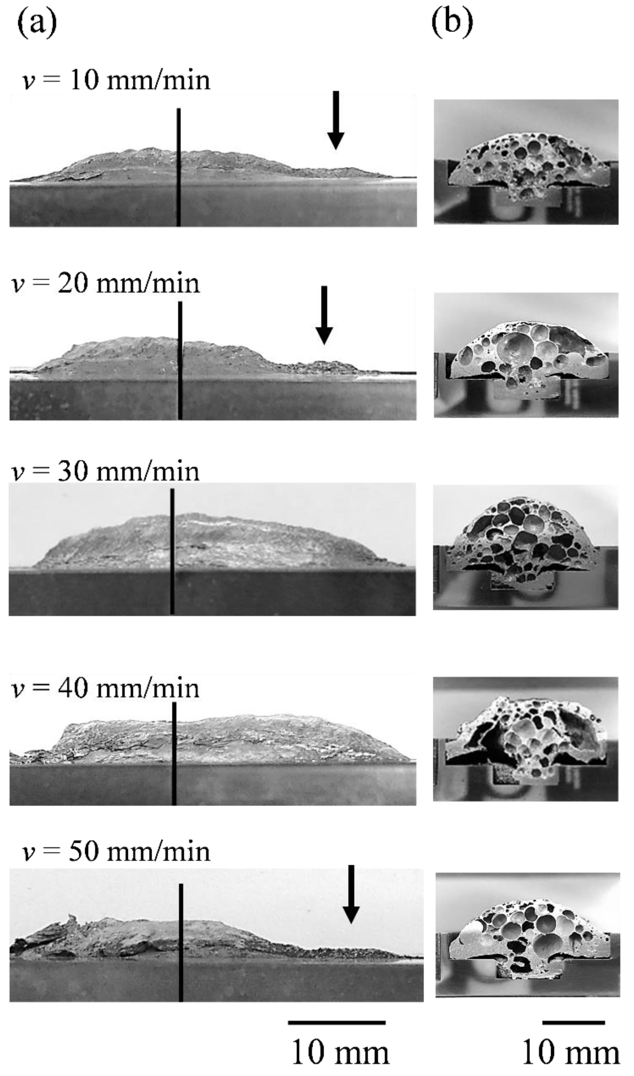
It was found that the precursors with fewer cracks and defects and porous Al with good pore structures could be fabricated at v = 10, 20, and 30 mm/min compare with those fabricated at v = 40 and 50 mm/min.

Author Contributions

Conceptualization, Y.H.; investigation, H.M. and H.M.; writing—original draft preparation, Y.H. and H.M.; writing—review and editing, Y.H. All authors have read and agreed to the published version of the manuscript.

Funding

This research was funded by JST-Mirai Program, grant number JPMJMI19E5, Japan.

Institutional Review Board Statement

Not applicable.

Informed Consent Statement

Not applicable.

Data Availability Statement

Not applicable.

Acknowledgments

This work was partly performed under the Cooperative Research Program of Institute for Joining and Welding Research Institute, Osaka University. The authors are grateful to Toyo Aluminium K.K. of Japan for providing the ADC12 alloy powder.

Conflicts of Interest

The authors declare no conflict of interest.

References

  1. Miyoshi, T.; Itoh, M.; Akiyama, S.; Kitahara, A. Alporas aluminum foam: Production process, properties, and applications. Adv. Eng. Mater. 2000, 2, 179–183. [Google Scholar] [CrossRef]
  2. Banhart, J. Manufacture, characterisation and application of cellular metals and metal foams. Prog. Mater. Sci. 2001, 46, 559–632. [Google Scholar] [CrossRef]
  3. García-Moreno, F. Commercial applications of metal foams: Their properties and production. Materials 2016, 9, 85. [Google Scholar] [CrossRef] [PubMed]
  4. Mishra, R.S.; Ma, Z.Y. Friction stir welding and processing. Mater. Sci. Eng. R Rep. 2005, 50, 1–78. [Google Scholar] [CrossRef]
  5. Cam, G.; Mistikoglu, S. Recent developments in friction stir welding of al-alloys. J. Mater. Eng. Perform. 2014, 23, 1936–1953. [Google Scholar] [CrossRef]
  6. Meng, X.; Huang, Y.; Cao, J.; Shen, J.; dos Santos, J.F. Recent progress on control strategies for inherent issues in friction stir welding. Prog. Mater. Sci. 2021, 115, 100706. [Google Scholar] [CrossRef]
  7. Janeczek, A.; Tomków, J.; Fydrych, D. The influence of tool shape and process parameters on the mechanical properties of aw-3004 aluminium alloy friction stir welded joints. Materials 2021, 14, 3244. [Google Scholar] [CrossRef] [PubMed]
  8. Hangai, Y.; Utsunomiya, T.; Hasegawa, M. Effect of tool rotating rate on foaming properties of porous aluminum fabricated by using friction stir processing. J. Mater. Process. Technol. 2010, 210, 288–292. [Google Scholar] [CrossRef]
  9. Hangai, Y.; Takahashi, K.; Yamaguchi, R.; Utsunomiya, T.; Kitahara, S.; Kuwazuru, O.; Yoshikawa, N. Nondestructive observation of pore structure deformation behavior of functionally graded aluminum foam by x-ray computed tomography. Mater. Sci. Eng. A 2012, 556, 678–684. [Google Scholar] [CrossRef]
  10. Papantoniou, I.G.; Kyriakopoulou, H.P.; Pantelis, D.I.; Manolakos, D.E. Fabrication of mwcnt-reinforced al composite local foams using friction stir processing route. Int. J. Adv. Manuf. Technol. 2018, 97, 675–686. [Google Scholar] [CrossRef]
  11. Shandley, R.; Maheshwari, S.; Siddiquee, A.N.; Mohammed, S.; Chen, D.L. Foaming of friction stir processed al/mgco3 precursor via flame heating. Mater. Res. Express 2020, 7, 026515. [Google Scholar] [CrossRef]
  12. Rathore, S.; Singh, R.K.R.; Khan, K.L.A. Effect of process parameters on mechanical properties of aluminum composite foam developed by friction stir processing. Proc. Inst. Mech. Eng. Part B J. Eng. Manuf. 2021, 235, 1892–1903. [Google Scholar] [CrossRef]
  13. Hangai, Y.; Takada, K.; Endo, R.; Fujii, H.; Aoki, Y.; Utsunomiya, T. Foaming of aluminum foam precursor during friction stir welding. J. Mater. Process. Technol. 2018, 259, 109–115. [Google Scholar] [CrossRef]
  14. Morohashi, H.; Hangai, Y.; Mitsugi, H.; Fujii, H.; Aoki, Y. Observation of porous ADC12 foaming and generated interfacial reaction layer by heat during friction stirring process of steel. J. Rep. Jpn. Foundry Eng. Soc. Meet. 2021, 177, 10. [Google Scholar]
  15. Tsuda, S.; Kobashi, M.; Kanetake, N. Producing technology of aluminum foam from machined chip waste. Mater. Trans. 2006, 47, 2125–2130. [Google Scholar] [CrossRef] [Green Version]
  16. Kanetake, N.; Kobashi, M.; Tsuda, S. Foaming behavior of aluminum precursor produced from machined chip waste. Adv. Eng. Mater. 2008, 10, 840–844. [Google Scholar] [CrossRef]
  17. Hangai, Y.; Amagai, K.; Omachi, K.; Tsurumi, N.; Utsunomiya, T.; Yoshikawa, N. Forming of aluminum foam using steel mesh as die during foaming of precursor by optical heating. Opt. Laser Technol. 2018, 108, 496–501. [Google Scholar] [CrossRef]
  18. Hangai, Y.; Amagai, K.; Tsurumi, N.; Omachi, K.; Shimizu, K.; Akimoto, K.; Utsunomiya, T.; Yoshikawa, N. Forming of aluminum foam using light-transmitting material as die during foaming by optical heating. Mater. Trans. 2018, 59, 1854–1859. [Google Scholar] [CrossRef] [Green Version]
  19. Hangai, Y.; Kawato, D.; Ohashi, M.; Ando, M.; Ogura, T.; Morisada, Y.; Fujii, H.; Kamakoshi, Y.; Mitsugi, H.; Amagai, K. X-ray radiography inspection of pores of thin aluminum foam during press forming immediately after foaming. Metals 2021, 11, 1226. [Google Scholar] [CrossRef]
  20. The-Japan-Institute-of-Light-Metals. Structures and Properties of Aluminum; The Japan Institute of Light Metals: Tokyo, Japan, 1991. [Google Scholar]
Figure 1. FSW process for fabrication of porous Al precursor (adapted from [13]). (a) Blowing agent powder was spread between the Al plates and laminated. (b) Blowing agent was distributed into the Al plates by FSW. (c) Precursor of porous Al was obtained.
Metals 12 00338 g001
Figure 2. Dimensions of SS400 steel plate.
Metals 12 00338 g002
Figure 3. SEM image of ADC12 powder.
Metals 12 00338 g003
Figure 4. (a) Setup of powders and plate. (b) Cross section along A-A in (a).
Metals 12 00338 g004
Figure 5. Setup for optical heating of precursor. (a) Precursor. (b) Beginning of heating. (c) Foaming.
Metals 12 00338 g005
Figure 6. (ac) Tool traversing behavior and (d) temperature history during precursor fabrication at v = 10 mm/min.
Metals 12 00338 g006
Figure 7. Enlarged cross section of precursor at v = 10 mm/min.
Metals 12 00338 g007
Figure 8. Surfaces and cross sections of precursors at various v.
Metals 12 00338 g008
Figure 9. (a) Porous Al obtained at various v. (b) Cross sections of porous Al shown in (a).
Metals 12 00338 g009
Publisher’s Note: MDPI stays neutral with regard to jurisdictional claims in published maps and institutional affiliations.

