
Numerical Analysis of Metal Transfer Process in Plasma MIG Welding

 , , , and
Abstract
:1. Introduction
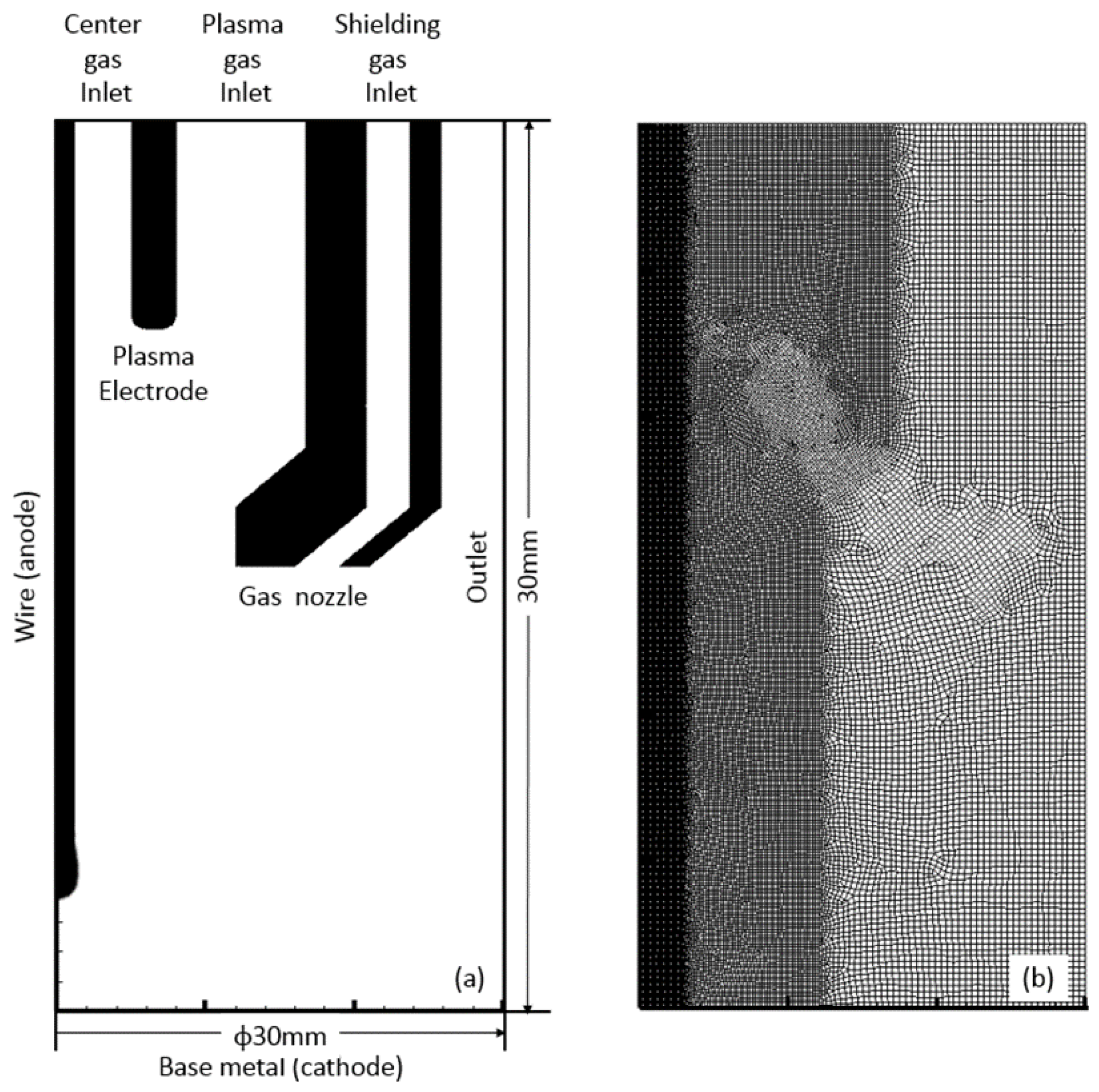
2. Simulation Model
3. Results and Discussion
4. Conclusions
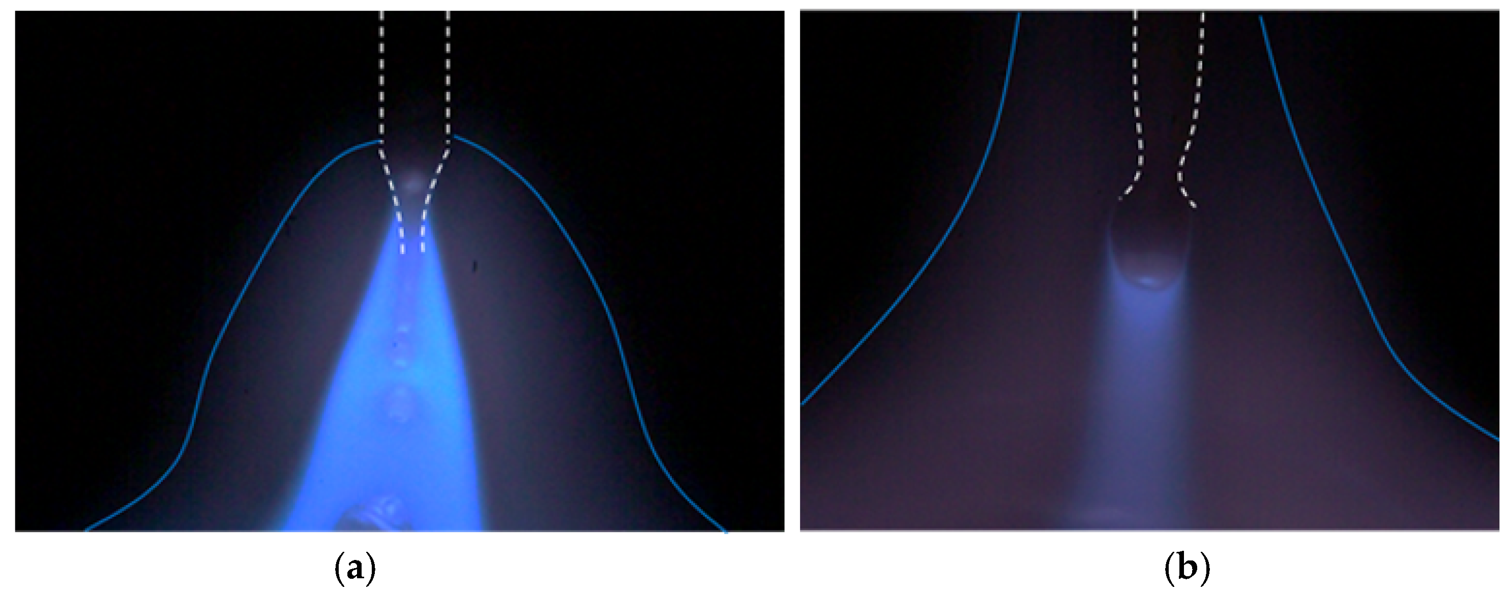
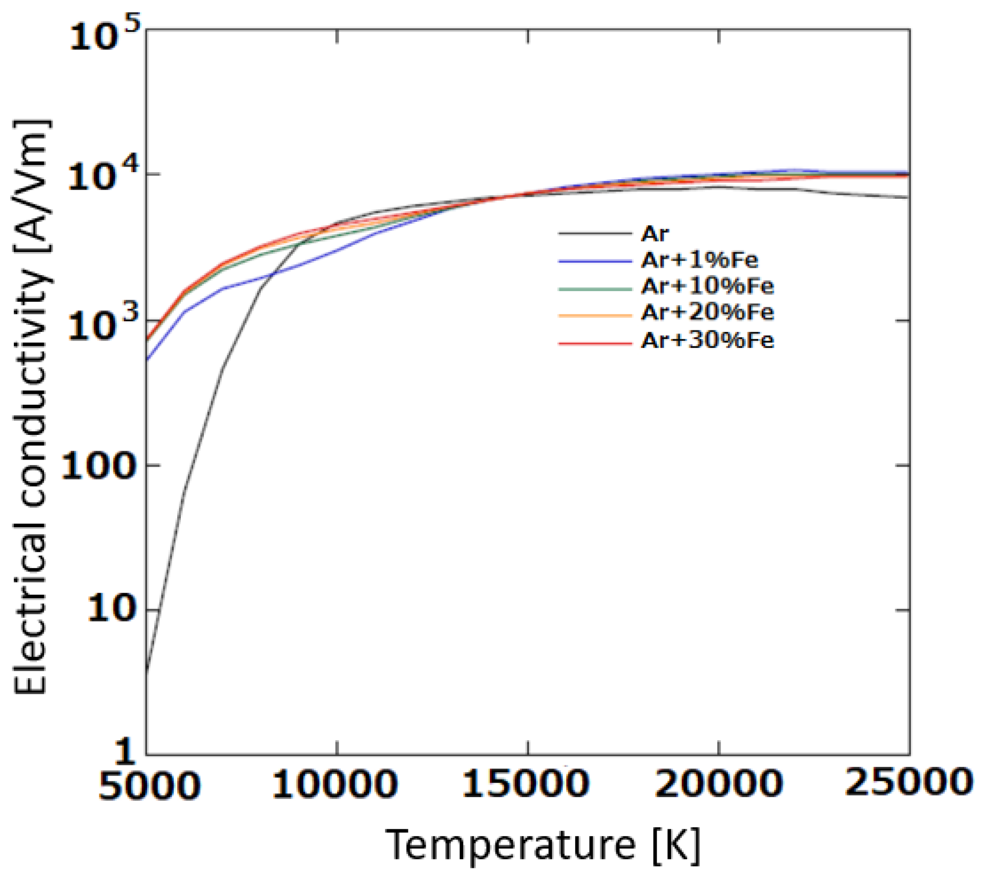
- In plasma MIG welding, the center gas and shielding gas are ionized in advance in an upstream region of the MIG arc, becoming plasma with a temperature of approximately 10,000 K.
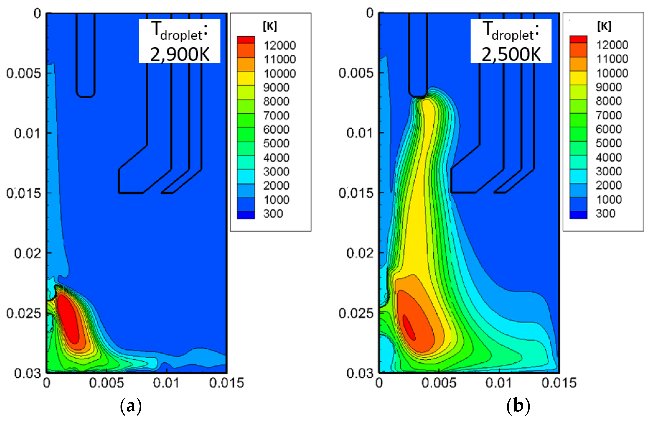
- The MIG arc temperature around the wire tip was 11,000 K at its maximum, which was lower than that of the conventional MIG welding by approximately 1000 K.
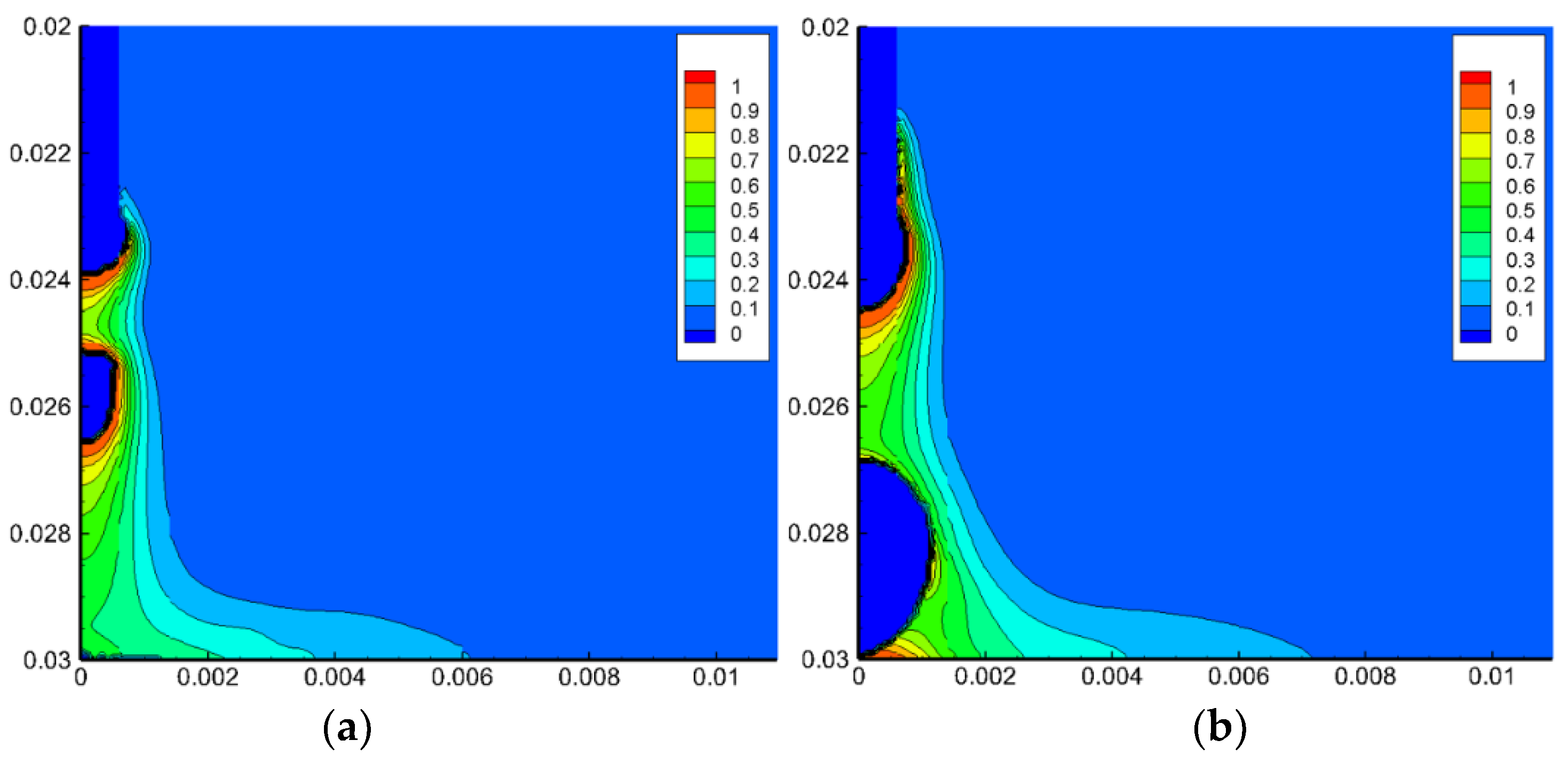
- In plasma–MIG welding, the droplet temperature is lower than that of the conventional MIG welding by 400 K, decreasing the amount of metal vapor that evaporated from the droplet.
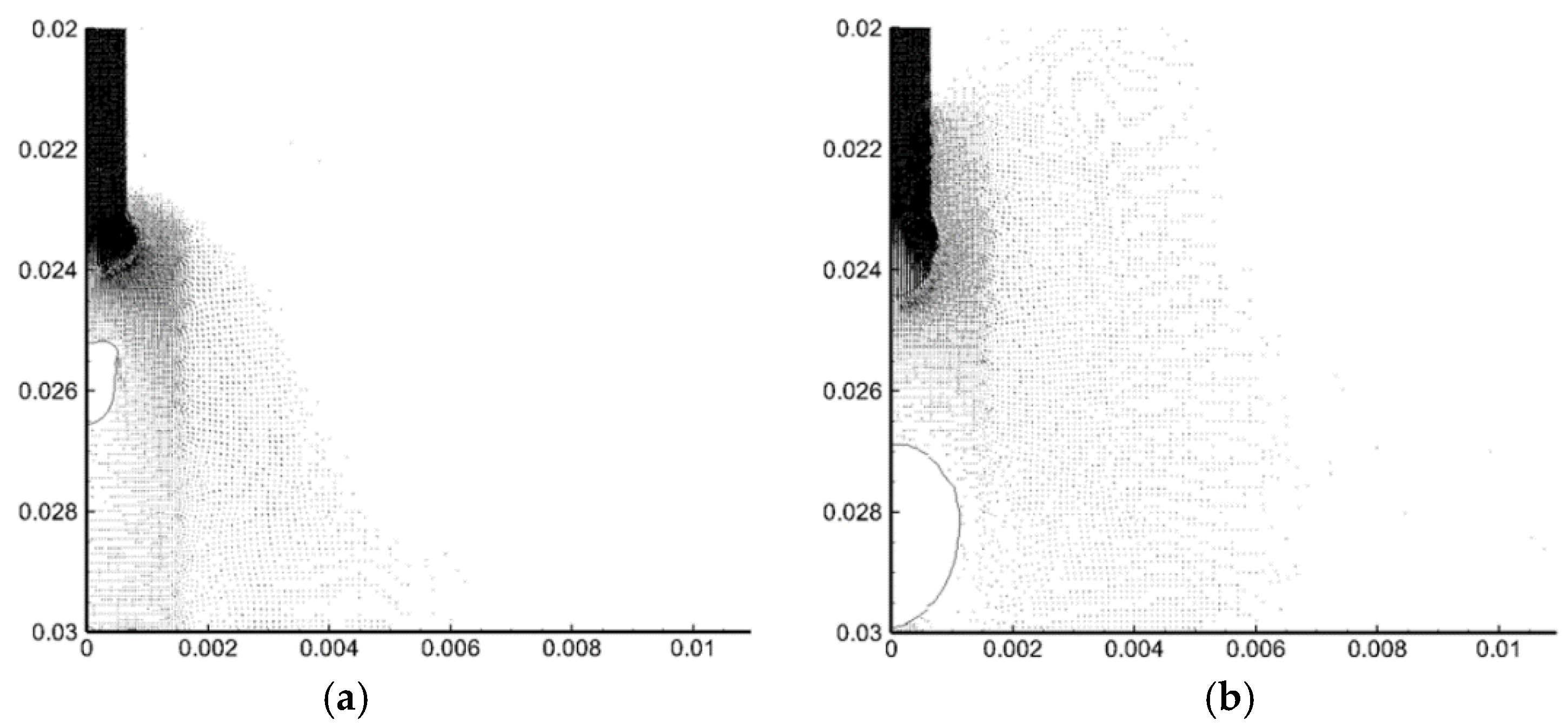
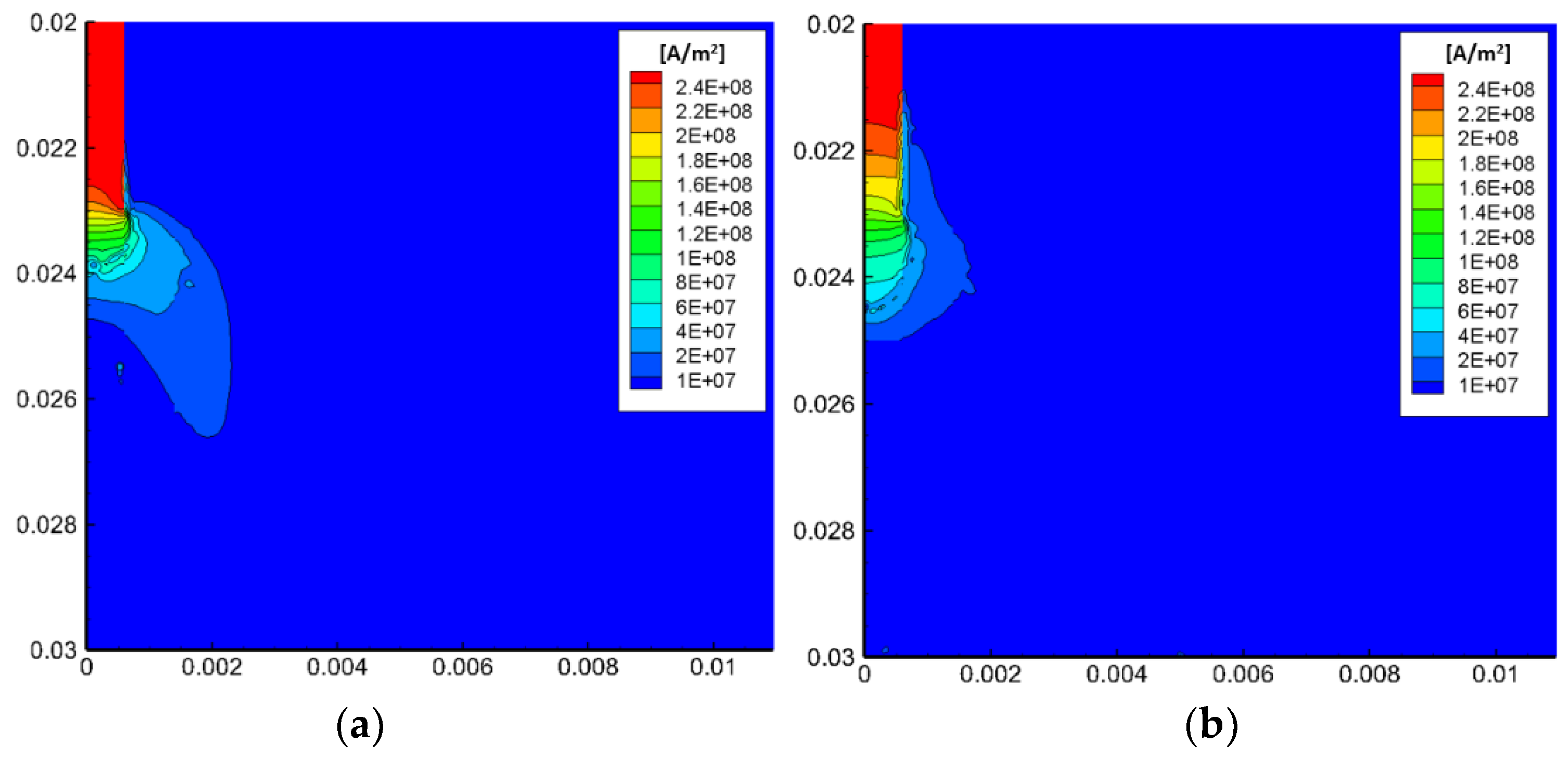
- The plasma transported to the surrounding of the wire tip increases the electric conductivity in that region. This leads to dispersion of the arc attachment toward the wire root.
- The current density in the plasma MIG welding is found to decrease compared with that of the conventional MIG welding, thereby causing decrease in the droplet temperature and metal transfer frequency. The latter was about 20% of that in the conventional MIG welding.
Author Contributions
Funding
Institutional Review Board Statement
Informed Consent Statement
Data Availability Statement
Conflicts of Interest
References
- Essers, W.G. New process combines plasma with GMA welding. Weld. J. 1976, 55, 394–400. [Google Scholar]
- Essers, W.G.; Jelmorini, G.; Tichelaar, G.W. The plasma-MIG welding process. Tool Alloy Steels 1978, 12, 275–277. [Google Scholar]
- Resende, A.A.; Ferraresi, V.A.; Scotti, A.; Dutra, J.C. Influence of welding current in plasma–MIG weld process on the bead weld geometry and wire fusion rate. Weld. Int. 2011, 25, 910–916. [Google Scholar] [CrossRef]
- Tanaka, M.; Tamaki, T.; Tashiro, S.; Nakata, K.; Ohnawa, T.; Ueyama, T. Characteristics of ionized gas metal arc processing. Surf. Coat. Technol. 2008, 202, 5251–5254. [Google Scholar] [CrossRef]
- Ono, K.; Liu, Z.; Era, T.; Uezono, T.; Ueyama, T.; Tanaka, T.; Nakata, K. Development of plasma MIG welding system for aluminum. J. Light Met. Weld. Constr. 2008, 46, 501–505. [Google Scholar]
- Katayama, T.; Tashiro, S.; Tanaka, M. Improvement of bead formation of plasma MIG welding in pure argon atmosphere. Q. J. Jpn. Weld. Soc. 2011, 29, 39s–42s. [Google Scholar] [CrossRef] [Green Version]
- Mamat, S.; Sidek, N.A.; Apandi, N.A.A.M.; Roslan, R.A.E.; Ter, T.P.; Yuji, T.; Tashiro, S.; Tanaka, M. Observation of Microstructure and Mechanical Properties in Heat Affected Zone of as-welded Carbon Steel by using Plasma MIG welding Process. Metals 2022, 12, 315. [Google Scholar] [CrossRef]
- Cai, D.; Han, S.; Zheng, S.; Luo, Z.; Zhang, Y.; Wang, K. Microstructure and corrosion resistance of Al5083 alloy hybrid plasma-MIG welds. J. Mater. Processing Tech. 2018, 255, 530–535. [Google Scholar] [CrossRef]
- Tsujimura, Y.; Tanaka, M. Numerical Simulation of heat source property with metal vapor behavior in GMA Welding. Q. J. Jpn. Weld. Soc. 2012, 30, 68–76. [Google Scholar] [CrossRef] [Green Version]
- Soderstrom, E.J.; Scott, K.M.; Mendez, P.F. Calorimetric Measurement of Droplet Temperature in GMAW. Weld. J. 2011, 90, 77S–84S. [Google Scholar]
- Mamat, S.B.; Tashiro, S.; Tanaka, M.; Yusoff, M. Study on factors affecting the droplet temperature in plasma MIG welding process. J. Phys. D Appl. Phys. 2018, 51, 135206. [Google Scholar] [CrossRef]
- Mamat, S.B.; Tashiro, S.; Masri, M.N.; Hong, S.M.; Bang, H.S.; Tanaka, M. Application of pulse plasma MIG welding process to Al/steel dissimilar joining. Weld. World 2020, 64, 857–871. [Google Scholar] [CrossRef]
- Boulos, M.I.; Fauchais, P.; Pfender, E. Thermal Plasmas: Fundamentals and Applications; Springer: New York, NY, USA, 1994; pp. 4–5. [Google Scholar]
- Murphy, A.B.; Arundell, C.J. Transport coefficients of argon, nitrogen, oxygen, argon-nitrogen and argon-oxygen plasmas. Plasma Chem. Plasma Process. 1994, 14, 451–490. [Google Scholar] [CrossRef]
- Hertel, M.; Spille-Kohoff, A.; Fussel, U.; Schnick, M. Numerical simulation of droplet detachment in pulsed gas–metal arc welding including the influence of metal vapour. J. Phys. D Appl. Phys. 2013, 46, 224003. [Google Scholar] [CrossRef]
- Tashiro, S.; Murphy, A.B.; Tanaka, M. Numerical simulation of fume formation process in GMA welding. Weld. World 2018, 62, 1332–1338. [Google Scholar] [CrossRef]
- Rouffet, M.E.; Wendt, M.; Goett, G.; Kozakov, R.; Schoepp, H.; Weltmann, K.D.; Uhrlandt, D. Spectroscopic investigation of the high-current phase of a pulsed GMAW process. J. Phys. D Appl. Phys. 2010, 43, 434003. [Google Scholar] [CrossRef] [Green Version]


| Parameters | Welding Processes | |
|---|---|---|
| Conventional MIG | Plasma–MIG | |
| Wire composition | Fe | |
| Wire diameter (mm) | 1.2 | |
| Wire feed speed (m/min) | 5.0 | |
| CTWD (mm) | 30.0 | |
| Plasma electrode diameter (mm) | 5.0 | |
| MIG current (A) | DCEP 280 | |
| Plasma current (A) | 0 | DCEP 100 |
| Gas composition | Pure Ar | |
| Center gas flow rate (L/min) | 5.0 | |
| Plasma gas flow rate (L/min) | 10.0 | |
| Shielding gas flow rate (L/min) | 10.0 | |
| Boundary | Mass and Momentum | Mass Fraction of Metal Vapor | Energy | Electric Potential | Magnetic Potential | |
|---|---|---|---|---|---|---|
| Top | Wire | wf | Y = 0 | 300 K | σ∂Φ/∂n = jMIG | ∂Ai/∂n = 0 |
| Center gas inlet | center gas | Y = 0 | 300 K | ∂Φ/∂n = 0 | ∂Ai/∂n = 0 | |
| Plasma electrode | - | - | 300 K | σ∂Φ/∂n = jplasma | ∂Ai/∂n = 0 | |
| Plasma gas inlet | plasma gas | Y = 0 | 300 K | ∂Φ/∂n = 0 | ∂Ai/∂n = 0 | |
| Shielding gas inlet | shielding gas | Y = 0 | 300 K | ∂Φ/∂n = 0 | ∂Ai/∂n = 0 | |
| Side | Outlet | P = 0 | ∂Y/∂n = 0 | 300 K | ∂Φ/∂n = 0 | Ai = 0 |
| Bottom | Base metal | = 0 | ∂Y/∂n = 0 | 300 K | Φ = 0 | ∂Ai/∂n = 0 |
Publisher’s Note: MDPI stays neutral with regard to jurisdictional claims in published maps and institutional affiliations. |
© 2022 by the authors. Licensee MDPI, Basel, Switzerland. This article is an open access article distributed under the terms and conditions of the Creative Commons Attribution (CC BY) license (https://creativecommons.org/licenses/by/4.0/).
Share and Cite
Tashiro, S.; Mamat, S.B.; Murphy, A.B.; Yuji, T.; Tanaka, M. Numerical Analysis of Metal Transfer Process in Plasma MIG Welding. Metals 2022, 12, 326. https://doi.org/10.3390/met12020326
Tashiro S, Mamat SB, Murphy AB, Yuji T, Tanaka M. Numerical Analysis of Metal Transfer Process in Plasma MIG Welding. Metals. 2022; 12(2):326. https://doi.org/10.3390/met12020326
Chicago/Turabian StyleTashiro, Shinichi, Sarizam Bin Mamat, Anthony B Murphy, Toshifumi Yuji, and Manabu Tanaka. 2022. "Numerical Analysis of Metal Transfer Process in Plasma MIG Welding" Metals 12, no. 2: 326. https://doi.org/10.3390/met12020326