
Comparison Study on Welding Temperature and Joint Characteristics of AZ31 Magnesium Alloy by Ultrasonic and Heat Pipe Assisted FSW


Abstract
:1. Introduction
2. Materials and Methods
2.1. Materials
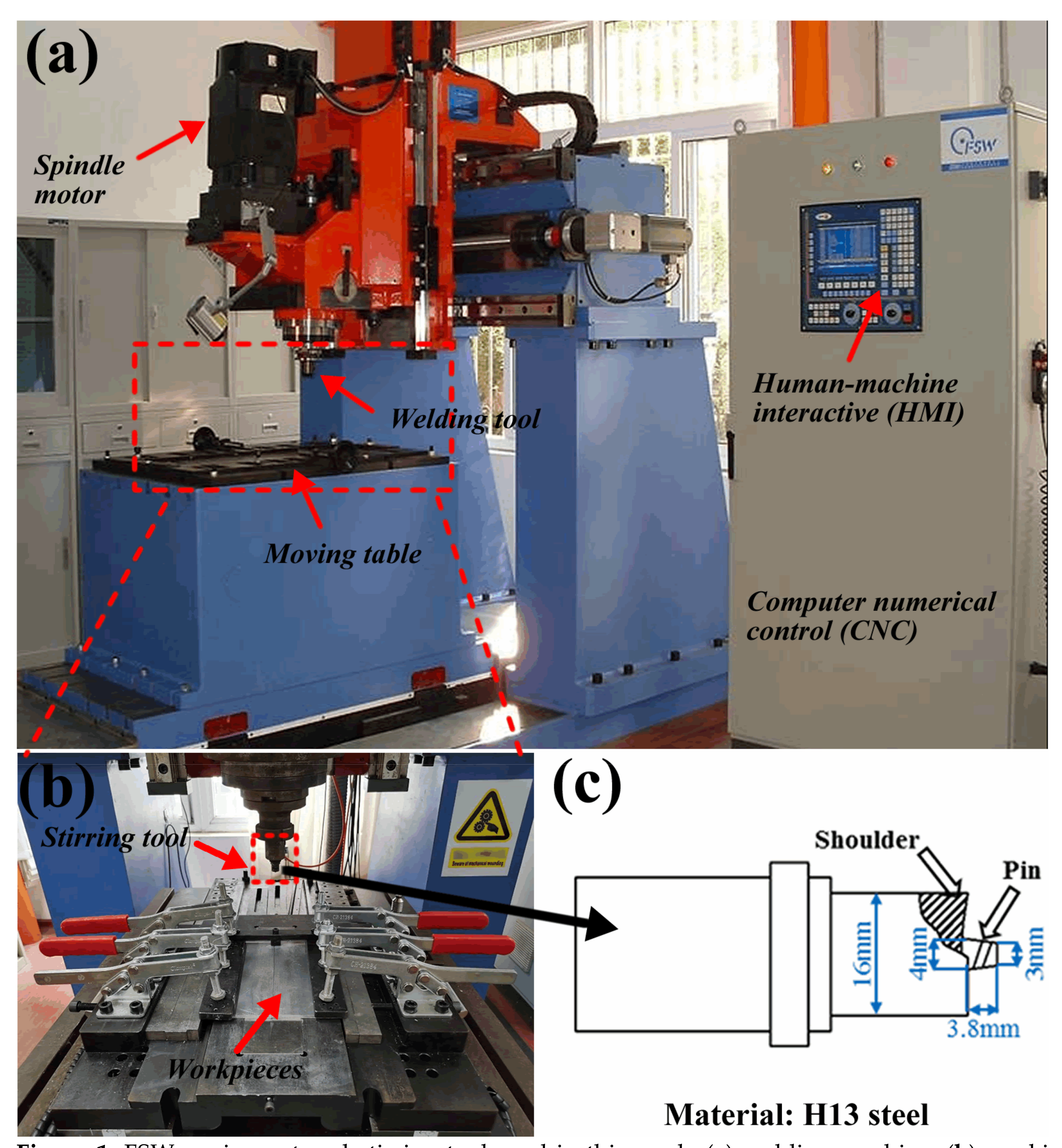
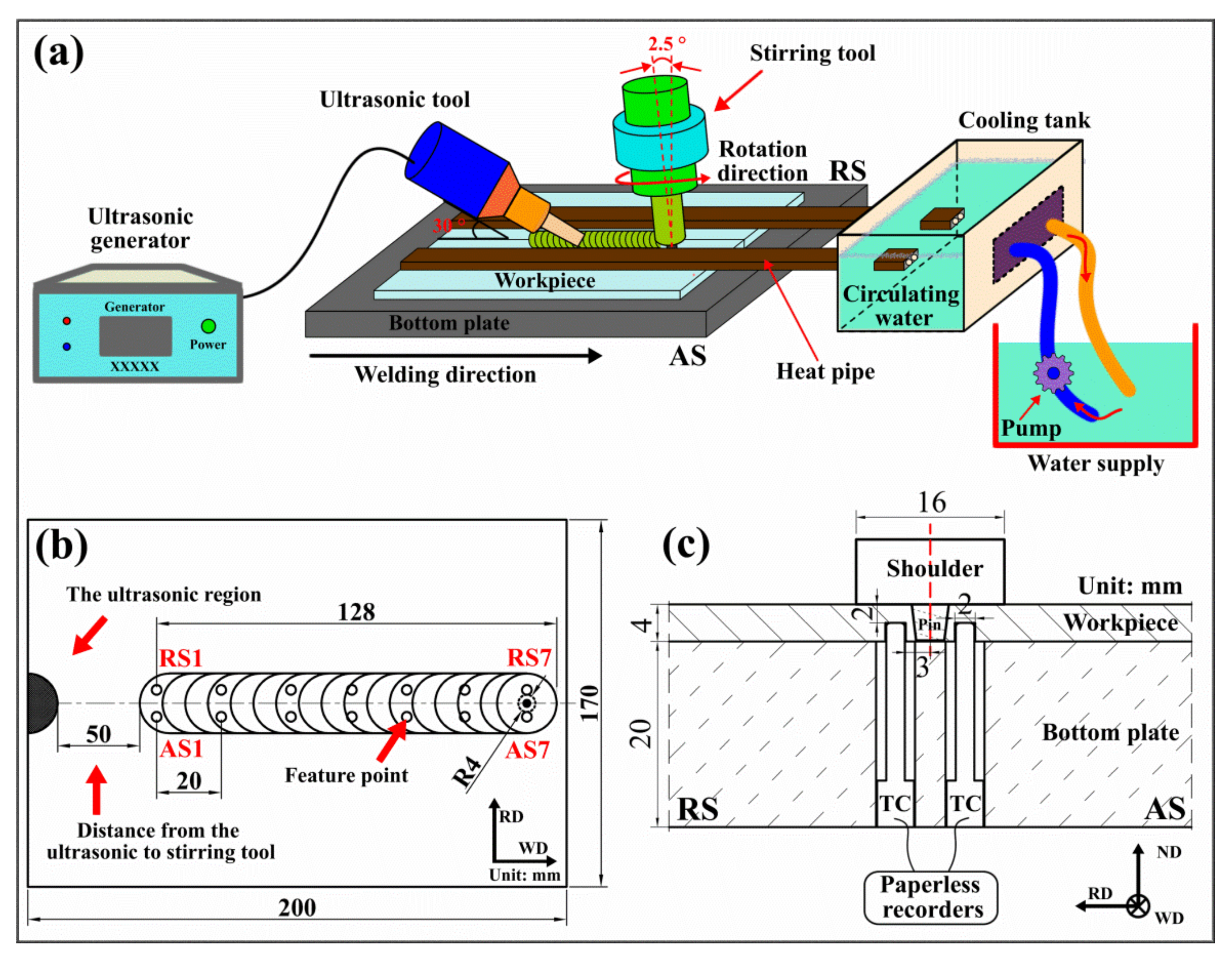
2.2. Methods
3. Results and Discussion
3.1. Thermal Cycle Curve and Temperature Distribution
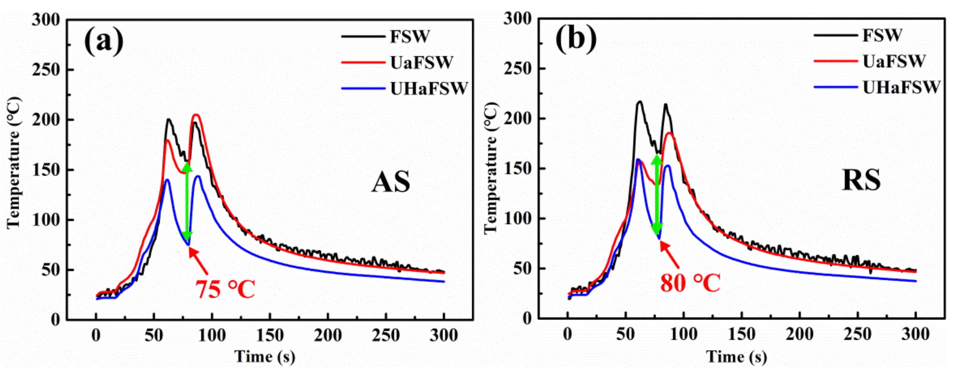
3.1.1. Thermal Cycle Curve with Dual Peaks Phenomenon
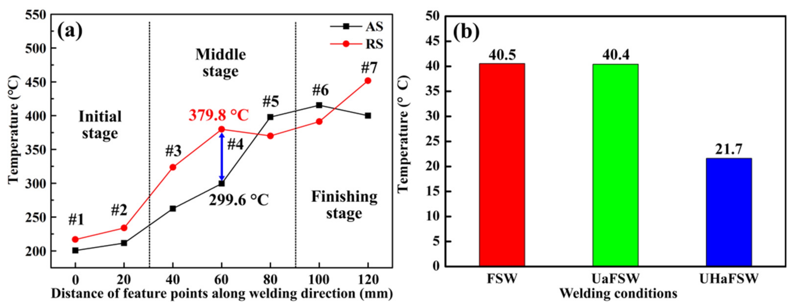
3.1.2. Non-Uniform Temperature Distribution
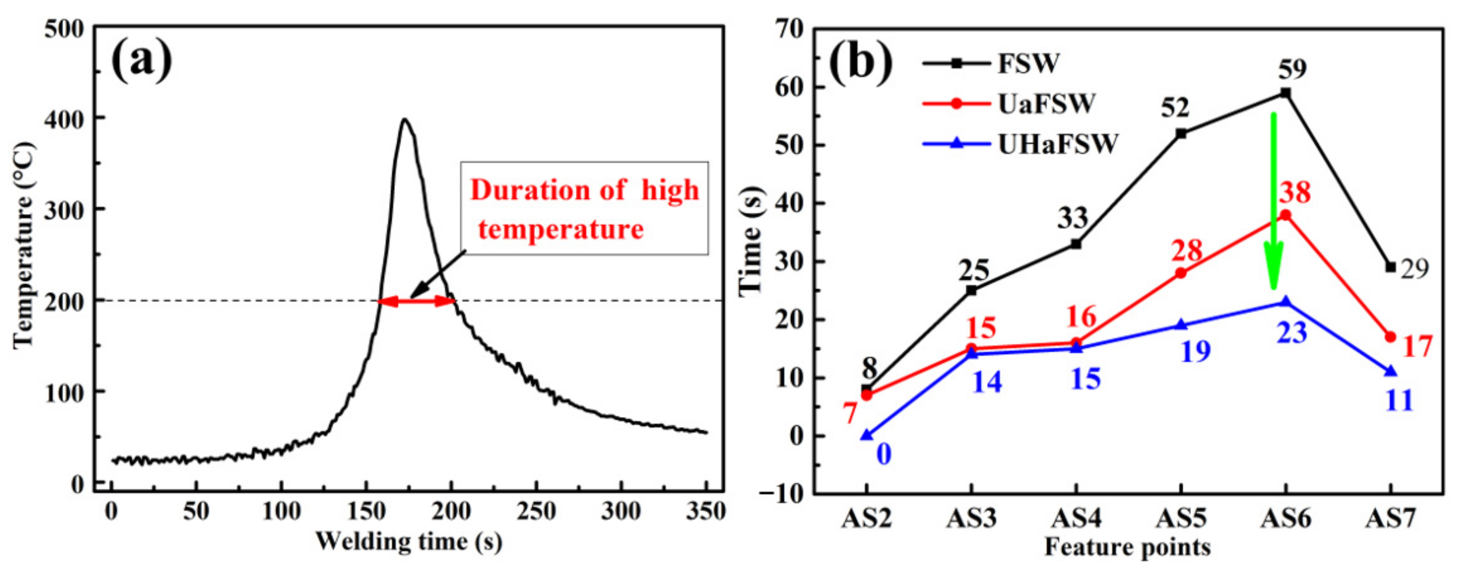
3.1.3. Duration and Effect of High Temperature
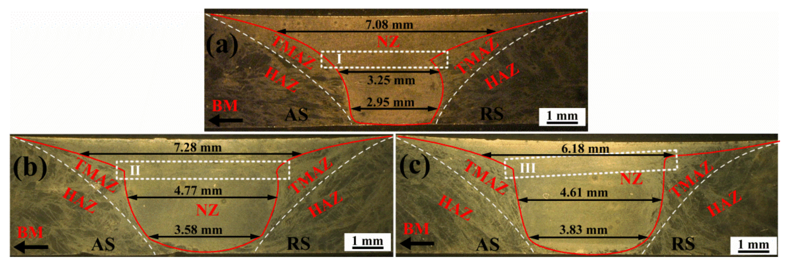
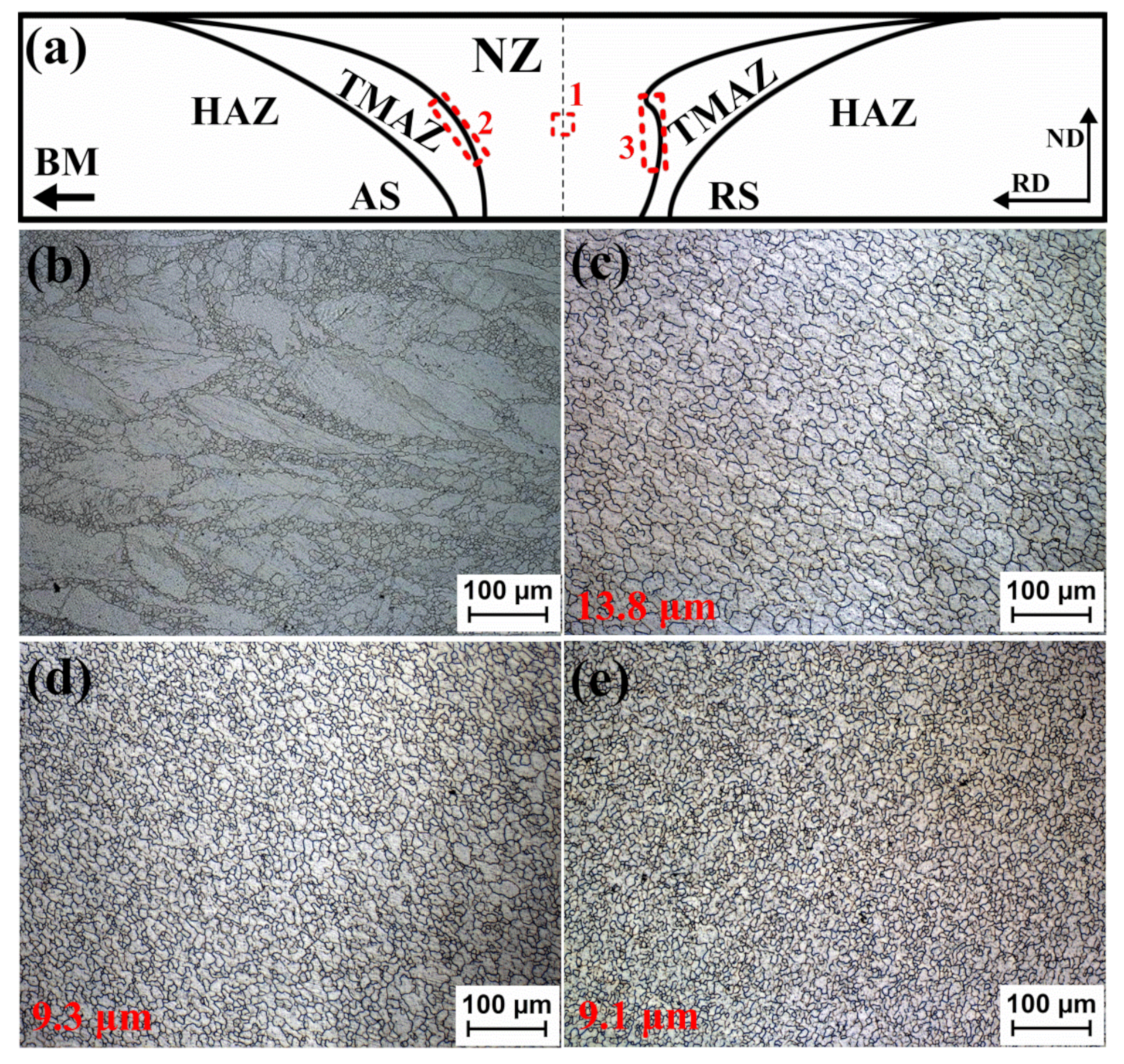
3.2. Microstructure
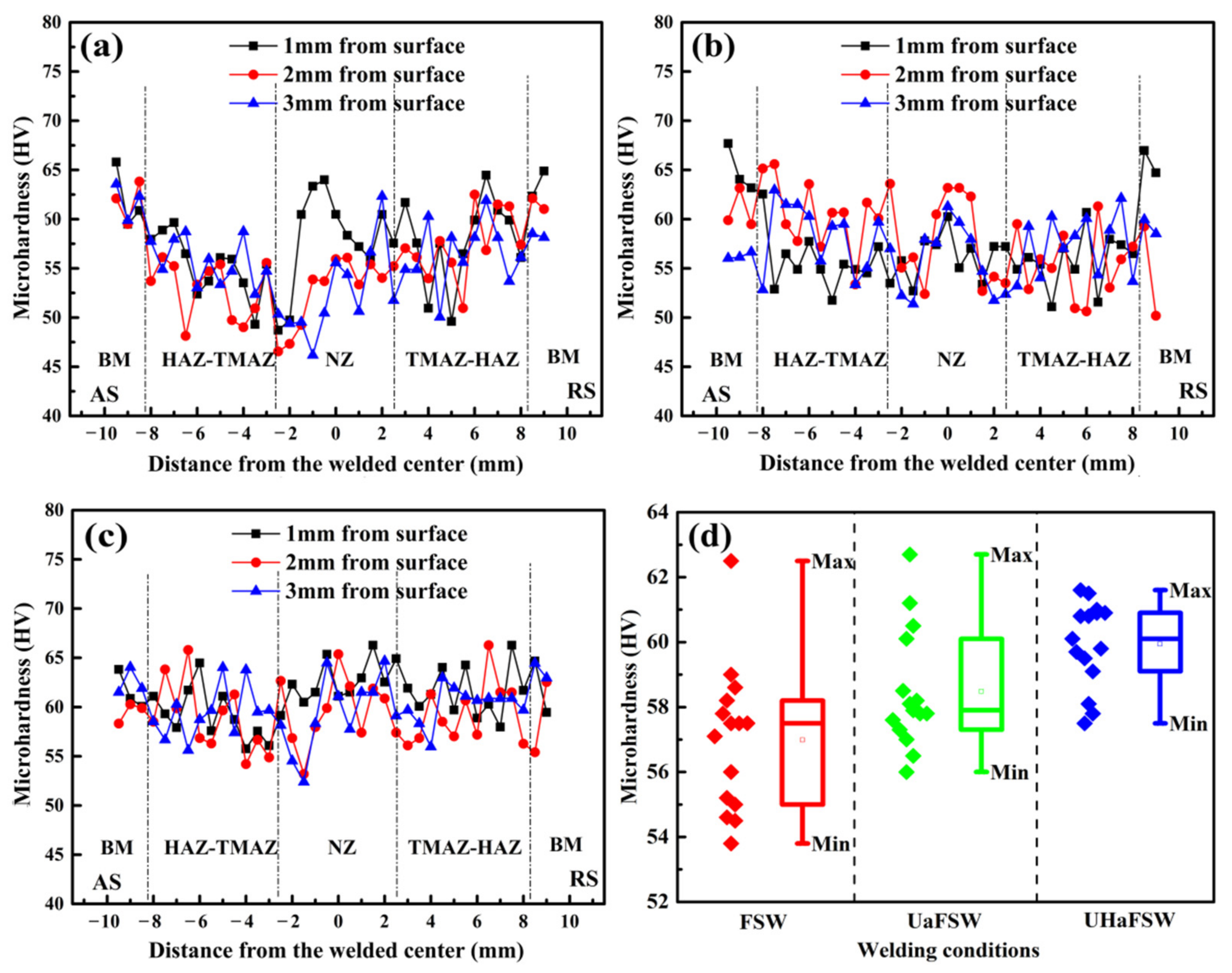
3.3. Microhardness
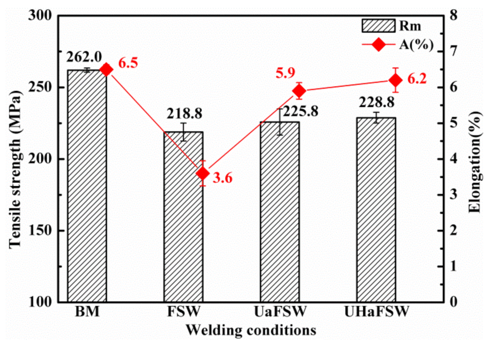
3.4. Tensile Properties and Fractographies
4. Conclusions
- (1)
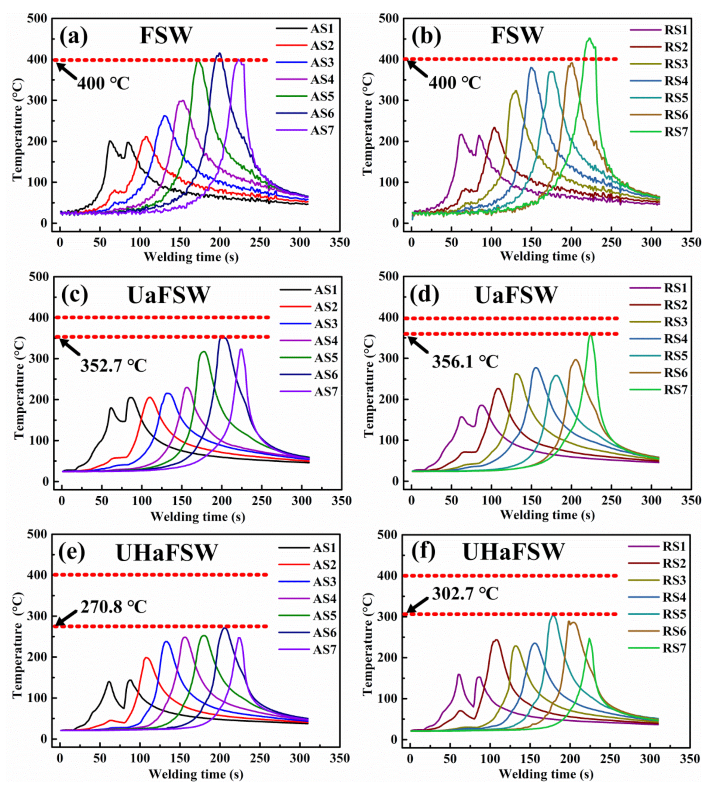
- During FSW process, the temperature distribution is non-uniform along the welding length and horizontal directions of the welded joint. A “dual peaks phenomenon” is presented at the initial stage of the FSW process, which can be obviously observed in the thermal cycle curve.
- (2)
- Compared with conventional FSW, UHaFSW can effectively balance and improve the “nonuniformity” in the welding temperature field via the significant decrease in the peak temperature and average peaks temperature difference between corresponding AS and RS. Meanwhile, with the assistance of ultrasonic and heat pipe, UHaFSW significantly reduces the durations of high temperature, which inhibits the grain coarsening of the welded AZ31 Mg alloy joints during the process and leads to the refined equiaxial grains in the nugget zone.
- (3)
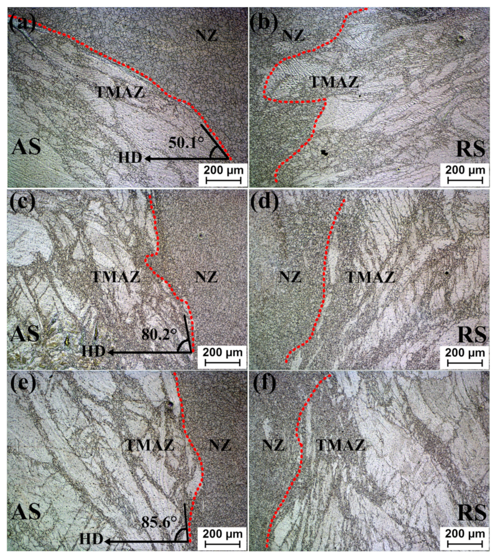
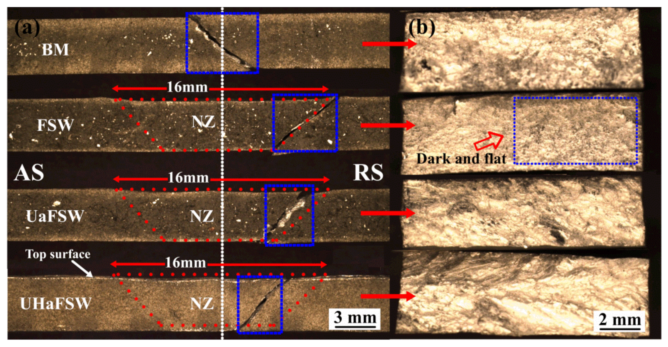
- The cross-section profiles of welded joints under three FSW conditions are similar to a typical “shallow funnel” which is wider at the top and narrower at the bottom. The widest region of the whole nugget zone is presented under the UaFSW condition, followed by UHaFSW and conventional FSW conditions since the ultrasonic vibration leads to the materials softening and the promotion in the plastic deformation.
- (4)
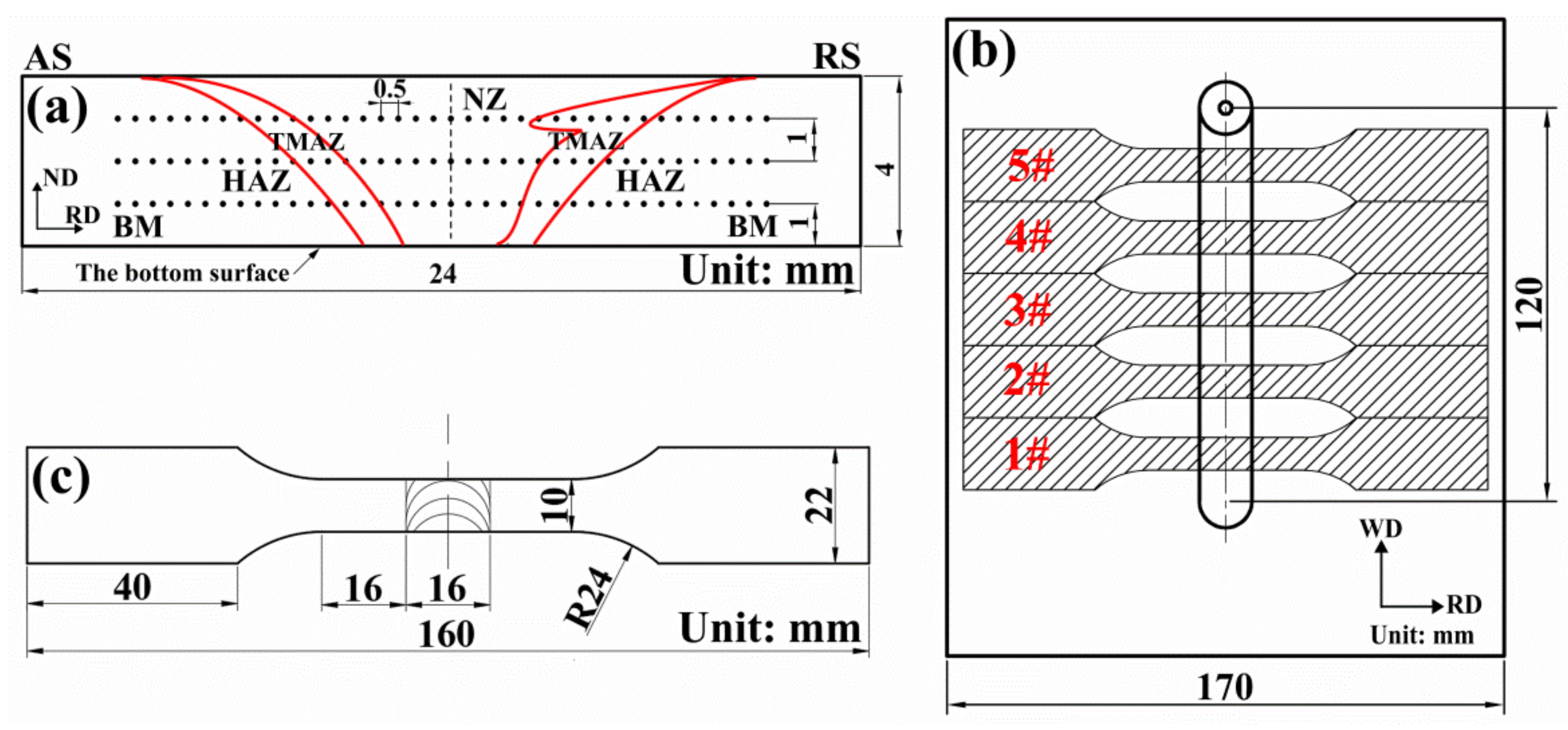
- Generally, compared with the base metal, the hardness across the whole welded joints declined after FSW, the hardness distribution profile presented a “W” pattern, and the lowest hardness locations are presented between TMAZ and NZ. Compared with other FSW conditions, the overall average microhardness of the joint produced by UHaFSW increases by 5.2% and 2.5%; the original “W” pattern of the hardness distribution profile is almost absent due to the homogeneous and refined microstructure.
- (5)
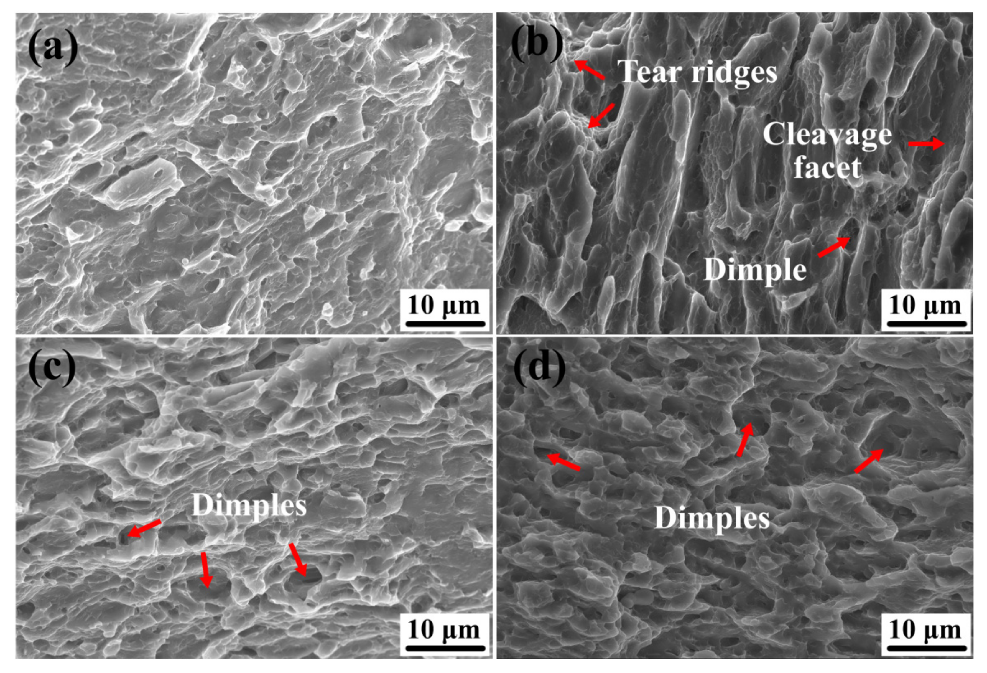
- Compared with the conventional FSW, the average tensile strength and elongation of the welded joints significantly increase under the UaFSW and UHaFSW conditions. Correspondingly, the fractographies exhibit more and finer dimples on the fractured surfaces of the joints under the UaFSW and UHaFSW conditions. Likewise, the fracture morphologies show the characteristic of microporous aggregate fracture, which indicates the increase of joints strength under the UaFSW and UHaFSW conditions.
Author Contributions
Funding
Data Availability Statement
Acknowledgments
Conflicts of Interest
References
- Wayne, M.; Edward, D.; James, C.; Michael, G.; Peter, T.; Christopher, J.S. Friction welding. Weld. J. 1999, 78, 56. [Google Scholar] [CrossRef]
- Nandan, R.; DebRoy, T.; Bhadeshia, H.K.D.H. Recent advances in friction-stir welding—Process, weldment structure and properties. Prog. Mater. Sci. 2008, 53, 980–1023. [Google Scholar] [CrossRef] [Green Version]
- Singh, K.; Singh, G.; Singh, H. Review on friction stir welding of magnesium alloys. J. Magnes. Alloy. 2018, 6, 399–416. [Google Scholar] [CrossRef]
- Eren, B.; Guvenc, M.A.; Mistikoglu, S. Artificial Intelligence Applications for Friction Stir Welding: A Review. Met. Mater. Int. 2021, 27, 193–219. [Google Scholar] [CrossRef]
- Laska, A.; Szkodo, M. Manufacturing parameters, materials, and welds properties of butt friction stir welded joints–overview. Materials 2020, 13, 4940. [Google Scholar] [CrossRef]
- Heidarzadeh, A.; Mironov, S.; Kaibyshev, R.; Çam, G.; Simar, A.; Gerlich, A.; Khodabakhshi, F.; Mostafaei, A.; Field, D.P.; Robson, J.D.; et al. Friction Stir Welding/Processing of Metals and Alloys: A Comprehensive Review on Microstructural Evolution. Prog. Mater. Sci. 2020, 117, 100752. [Google Scholar] [CrossRef]
- Meng, X.; Huang, Y.; Cao, J.; Shen, J.; dos Santos, J.F. Recent progress on control strategies for inherent issues in friction stir welding. Prog. Mater. Sci. 2021, 115, 100706. [Google Scholar] [CrossRef]
- He, X.; Gu, F.; Ball, A. A review of numerical analysis of friction stir welding. Prog. Mater. Sci. 2014, 65, 1–66. [Google Scholar] [CrossRef] [Green Version]
- Wang, L.; Xie, L.; Lv, Y.; Zhang, L.C.; Chen, L.; Meng, Q.; Qu, J.; Zhang, D.; Lu, W. Microstructure evolution and superelastic behavior in Ti-35Nb-2Ta-3Zr alloy processed by friction stir processing. Acta Mater. 2017, 131, 499–510. [Google Scholar] [CrossRef] [Green Version]
- Xu, N.; Zhang, W.; Cai, S.; Zhuo, Y.; Song, Q.; Bao, Y. Microstructure and tensile properties of rapid-cooling friction-stir-welded AZ31B Mg alloy along thickness direction. Trans. Nonferrous Met. Soc. China Engl. Ed. 2020, 30, 3254–3262. [Google Scholar] [CrossRef]
- Mehta, K.P.; Carlone, P.; Astarita, A.; Scherillo, F.; Rubino, F.; Vora, P. Conventional and cooling assisted friction stir welding of AA6061 and AZ31B alloys. Mater. Sci. Eng. A 2019, 759, 252–261. [Google Scholar] [CrossRef]
- Chowdhury, S.H.; Chen, D.L.; Bhole, S.D.; Cao, X.; Wanjara, P. Friction stir welded AZ31 magnesium alloy: Microstructure, texture, and tensile properties. Metall. Mater. Trans. A Phys. Metall. Mater. Sci. 2013, 44, 323–336. [Google Scholar] [CrossRef]
- Silva-Magalhães, A.; De Backer, J.; Martin, J.; Bolmsjö, G. In-situ temperature measurement in friction stir welding of thick section aluminium alloys. J. Manuf. Process. 2019, 39, 12–17. [Google Scholar] [CrossRef]
- Mironov, S.; Sato, Y.S.; Kokawa, H. Influence of welding temperature on material flow during friction stir welding of AZ31 magnesium alloy. Metall. Mater. Trans. A Phys. Metall. Mater. Sci. 2019, 50, 2798–2806. [Google Scholar] [CrossRef] [Green Version]
- Bilgin, M.; Karabulut, Ş.; Özdemir, A. Investigation of Heat-Assisted Dissimilar Friction Stir Welding of AA7075-T6 Aluminum and AZ31B Magnesium Alloys. Arab. J. Sci. Eng. 2020, 45, 1081–1095. [Google Scholar] [CrossRef]
- Padhy, G.K.; Wu, C.S.; Gao, S. Precursor ultrasonic effect on grain structure development of AA6061-T6 friction stir weld. Mater. Des. 2017, 116, 207–218. [Google Scholar] [CrossRef]
- Liu, H.; Hu, Y.; Du, S.; Zhao, H. Microstructure characterization and mechanism of acoustoplastic effect in friction stir welding assisted by ultrasonic vibrations on the bottom surface of workpieces. J. Manuf. Process. 2019, 42, 159–166. [Google Scholar] [CrossRef]
- Zhang, Z.; He, C.; Li, Y.; Yu, L.; Zhao, S.; Zhao, X. Effects of ultrasonic assisted friction stir welding on flow behavior, microstructure and mechanical properties of 7N01-T4 aluminum alloy joints. J. Mater. Sci. Technol. 2020, 43, 1–13. [Google Scholar] [CrossRef]
- Shi, L.; Wu, C.S.; Liu, X.C. Modeling the effects of ultrasonic vibration on friction stir welding. J. Mater. Process. Technol. 2015, 222, 91–102. [Google Scholar] [CrossRef]
- Liu, Z.; Ji, S.; Meng, X. Joining of magnesium and aluminum alloys via ultrasonic assisted friction stir welding at low temperature. Int. J. Adv. Manuf. Technol. 2018, 97, 4127–4136. [Google Scholar] [CrossRef]
- Zhong, Y.B.; Wu, C.S.; Padhy, G.K. Effect of ultrasonic vibration on welding load, temperature and material flow in friction stir welding. J. Mater. Process. Technol. 2017, 239, 273–283. [Google Scholar] [CrossRef]
- Ma, Z.Y.; Feng, A.H.; Chen, D.L.; Shen, J. Recent Advances in Friction Stir Welding/Processing of Aluminum Alloys: Microstructural Evolution and Mechanical Properties. Crit. Rev. Solid State Mater. Sci. 2018, 43, 269–333. [Google Scholar] [CrossRef]
- Reay, D.A.; Kew, P.A. 7—Applications of the Heat Pipe. In Heat Pipes, 5th ed.; Kew, P.A., Ed.; Butterworth-Heinemann: Oxford, UK, 2007; pp. 275–317. ISBN 9780750667548. [Google Scholar]
- Zhang, H.; Zhuang, J. Research, development and industrial application of heat pipe technology in China. Appl. Therm. Eng. 2003, 23, 1067–1083. [Google Scholar] [CrossRef]
- Bahmani, M.H.; Sheikhzadeh, G.; Zarringhalam, M.; Akbari, O.A.; Alrashed, A.A.A.A.; Shabani, G.A.S.; Goodarzi, M. Investigation of turbulent heat transfer and nanofluid flow in a double pipe heat exchanger. Adv. Powder Technol. 2018, 29, 273–282. [Google Scholar] [CrossRef]
- Faghri, A.; Guo, Z. Integration of heat pipe into fuel cell technology. Heat Transf. Eng. 2008, 29, 232–238. [Google Scholar] [CrossRef]
- Antariksawan, A.R.; Juarsa, M.; Sundari, T.; Ismarwanti, S.; Widodo, S.; Kusuma, M.H.; Subekti, M.; Putra, N. Study of heat transfer in a water cooling tank with c-shaped heat exchanger and straight heat pipe under natural circulation. AIP Conf. Proc. 2019, 2062, 020007. [Google Scholar] [CrossRef]
- Lu, S.; Zhang, W.; Chen, S.; Yao, S. Effect of flat heat pipe on the properties of the FSW joint. Mater. Sci. Forum 2016, 850, 693–699. [Google Scholar] [CrossRef]
- Zhang, Y.-M.; Chen, L.-Y.; Lu, S.; Zhao, C.; Wang, Y.-H. Refined Microstructure and Enhanced Hardness in Friction Stir-Welded AZ31 Magnesium Alloy Induced by Heat Pipe with Different Cooling Liquid. Metals 2019, 9, 1227. [Google Scholar] [CrossRef] [Green Version]
- ASTM. ASTM E112-13: Standard test methods for determining average grain size. ASTM Int. 2013, 3, 1–28. [Google Scholar] [CrossRef]
- Rubino, F.; Parmar, H.; Esperto, V.; Carlone, P. Ultrasonic welding of magnesium alloys: A review. Mater. Manuf. Process. 2020, 35, 1051–1068. [Google Scholar] [CrossRef]
- Sheng, L.; Jing, C.; Jia, X.D.; Wang, Z.X.; Gong, J.J. Thermal cycle characteristics of AM 50 magnesium alloy welded by FSW. Key Eng. Mater. 2010, 419–420, 533–536. [Google Scholar] [CrossRef]
- Keivani, R.; Bagheri, B.; Sharifi, F.; Ketabchi, M.; Abbasi, M. Effects of pin angle and preheating on temperature distribution during friction stir welding operation. Trans. Nonferrous Met. Soc. China Engl. Ed. 2013, 23, 2708–2713. [Google Scholar] [CrossRef]
- Cho, J.-H.; Boyce, D.E.; Dawson, P.R. Modeling strain hardening and texture evolution in friction stir welding of stainless steel. Mater. Sci. Eng. A 2005, 398, 146–163. [Google Scholar] [CrossRef]
- Yan, F.; Zhang, Y.C.; Shen, J.; Fu, X.B.; Mi, S. A new calculation method of viscoplastic heat production generated by plastic flow of friction stir welding process. Mater. Chem. Phys. 2021, 270, 124795. [Google Scholar] [CrossRef]
- Abbasi, M.; Bagheri, B.; Sharifi, F. Simulation and experimental study of dynamic recrystallization process during friction stir vibration welding of magnesium alloys. Trans. Nonferrous Met. Soc. China Engl. Ed. 2021, 31, 2626–2650. [Google Scholar] [CrossRef]
- Su, C.W.; Lu, L.; Lai, M.O. Recrystallization and grain growth of deformed magnesium alloy. Philos. Mag. 2008, 88, 181–200. [Google Scholar] [CrossRef]
- Ugender, S. Influence of tool pin profile and rotational speed on the formation of friction stir welding zone in AZ31 magnesium alloy. J. Magnes. Alloy. 2018, 6, 205–213. [Google Scholar] [CrossRef]
- Naik, B.S.; Chen, D.L.; Cao, X.; Wanjara, P. Texture development in a friction stir lap-welded AZ31B magnesium alloy. Metall. Mater. Trans. A Phys. Metall. Mater. Sci. 2014, 45, 4333–4349. [Google Scholar] [CrossRef]
- Zang, Q.; Chen, H.; Lan, F.; Zhang, J.; Jin, Y. Effect of friction stir processing on microstructure and damping capacity of AZ31 alloy. J. Cent. South Univ. 2017, 24, 1034–1039. [Google Scholar] [CrossRef]
- Wlodarski, S.; Avery, D.Z.; White, B.C.; Mason, C.J.T.; Cleek, C.; Williams, M.B.; Allison, P.G.; Jordon, J.B. Evaluation of Grain Refinement and Mechanical Properties of Additive Friction Stir Layer Welding of AZ31 Magnesium Alloy. J. Mater. Eng. Perform. 2021, 30, 964–972. [Google Scholar] [CrossRef]
- Commin, L.; Dumont, M.; Masse, J.E.; Barrallier, L. Friction stir welding of AZ31 magnesium alloy rolled sheets: Influence of processing parameters. Acta Mater. 2009, 57, 326–334. [Google Scholar] [CrossRef] [Green Version]
- Han, G.; Lee, K.; Yoon, J.Y.; Na, T.W.; Ahn, K.; Kang, M.J.; Jun, T.S. Effect of post-weld heat treatment on mechanical properties of local weld-affected zones in friction stir welded AZ31 plates. Mater. Sci. Eng. A 2021, 805, 140809. [Google Scholar] [CrossRef]
- Shang, Q.; Ni, D.R.; Xue, P.; Xiao, B.L.; Wang, K.S.; Ma, Z.Y. An approach to enhancement of Mg alloy joint performance by additional pass of friction stir processing. J. Mater. Process. Technol. 2019, 264, 336–345. [Google Scholar] [CrossRef]
- Sahu, P.K.; Das, J.; Chen, G.; Liu, Q.; Pal, S.; Zeng, S.; Shi, Q. Friction stir selective alloying of different Al% particulate reinforced to AZ31 Mg for enhanced mechanical and metallurgical properties. Mater. Sci. Eng. A 2020, 774, 138889. [Google Scholar] [CrossRef]
- Han, Y.; Jiang, X.; Chen, S.; Yuan, T.; Zhang, H.; Bai, Y.; Xiang, Y.; Li, X. Microstructure and mechanical properties of electrically assisted friction stir welded AZ31B alloy joints. J. Manuf. Process. 2019, 43, 26–34. [Google Scholar] [CrossRef]
- Wang, G.; Yan, Z.; Zhang, H.; Zhang, X.; Liu, F.; Wang, X.; Su, Y. Improved properties of friction stir-welded AZ31 magnesium alloy by post-weld heat treatment. Mater. Sci. Technol. 2017, 33, 854–863. [Google Scholar] [CrossRef]
- Zhang, J.; Chen, X.; Liu, S.; Huang, G.; Jiang, B.; Tang, A.; Pan, F. Non-uniform deformation behavior of dissimilar friction stir welded AM60/AZ31 joint and its influence on fracture. Mater. Sci. Eng. A 2021, 800, 140318. [Google Scholar] [CrossRef]
- Cao, Y.; Ni, S.; Liao, X.; Song, M.; Zhu, Y. Structural evolutions of metallic materials processed by severe plastic deformation. Mater. Sci. Eng. R Rep. 2018, 133, 1–59. [Google Scholar] [CrossRef]
- Commin, L.; Dumont, M.; Rotinat, R.; Pierron, F.; Masse, J.-E.; Barrallier, L. Influence of the microstructural changes and induced residual stresses on tensile properties of wrought magnesium alloy friction stir welds. Mater. Sci. Eng. A 2012, 551, 288–292. [Google Scholar] [CrossRef] [Green Version]
- Hou, Z.; Sheikh-Ahmad, J.; Jarrar, F.; Ozturk, F. Residual Stresses in Dissimilar Friction Stir Welding of AA2024 and AZ31: Experimental and Numerical Study. J. Manuf. Sci. Eng. Trans. ASME 2018, 5. [Google Scholar] [CrossRef]


| Al | Si | Ca | Zn | Mn | Fe | Cu | Ni | Mg |
|---|---|---|---|---|---|---|---|---|
| 3.240 | 0.024 | 0.002 | 1.140 | 0.313 | 0.008 | 0.001 | 0.002 | Bal. |
| Parameters | Values |
|---|---|
| Rotational Speed | 1500 rpm |
| Welding Velocity | 50 mm/min |
| Pin Length | 3.85 mm |
| Shoulder Diameter | 16 mm |
| Pin Diameter | 3 mm |
| Tilt Angle | 2.5° |
Publisher’s Note: MDPI stays neutral with regard to jurisdictional claims in published maps and institutional affiliations. |
© 2022 by the authors. Licensee MDPI, Basel, Switzerland. This article is an open access article distributed under the terms and conditions of the Creative Commons Attribution (CC BY) license (https://creativecommons.org/licenses/by/4.0/).
Share and Cite
Wei, C.-G.; Lu, S.; Chen, L.-Y.; Xu, M.-Y. Comparison Study on Welding Temperature and Joint Characteristics of AZ31 Magnesium Alloy by Ultrasonic and Heat Pipe Assisted FSW. Metals 2022, 12, 267. https://doi.org/10.3390/met12020267
Wei C-G, Lu S, Chen L-Y, Xu M-Y. Comparison Study on Welding Temperature and Joint Characteristics of AZ31 Magnesium Alloy by Ultrasonic and Heat Pipe Assisted FSW. Metals. 2022; 12(2):267. https://doi.org/10.3390/met12020267
Chicago/Turabian StyleWei, Cheng-Gang, Sheng Lu, Liang-Yu Chen, and Mao-You Xu. 2022. "Comparison Study on Welding Temperature and Joint Characteristics of AZ31 Magnesium Alloy by Ultrasonic and Heat Pipe Assisted FSW" Metals 12, no. 2: 267. https://doi.org/10.3390/met12020267