Article

The Deformation Characteristics and Effect of Processing Parameters on the Microstructure of 7075 Al Shell Part Manufactured by Rotating Backward Extrusion

1
School of Materials Science and Engineering, Hefei University of Technology, Hefei 230009, China
2
Ningbo Branch of China Academy of Ordnance Science, China Academy of Ordnance Science, Ningbo 315103, China
3
School of Mechanical and Electrical Engineering, North University of China, Taiyuan 030051, China
4
Ningbo Surface Engineering Research Institute Co., Ltd., Ningbo 315177, China
*
Author to whom correspondence should be addressed.
Co-first author.
Metals 2022, 12(2), 227; https://doi.org/10.3390/met12020227
Submission received: 30 December 2021 / Revised: 17 January 2022 / Accepted: 17 January 2022 / Published: 26 January 2022
(This article belongs to the Topic Advanced Forming Technology of Metallic Materials)

Abstract

:
Rotating backward extrusion (RBE) is known as a new severe plastic deformation technology that effectively combines the features of conventional backward extrusion (CBE) and torsion deformation. In this study, 7075 Al alloy shell parts were successfully prepared by CBE and RBE with a different number of revolutions (N = 5, 10, 15, 25, 50) at 410 °C. The effects of the RBE process on the grain refinement, precipitates and properties of extruded parts were revealed, and the deformation characteristics were compared with CBE. The results showed that the RBE process could greatly eliminate the dead deformation zone at the bottom of the CBE section and significantly improved the comprehensive strain level of the material due to the addition of severe torsional deformation via an open punch. The grain refinement feature of RBE parts showed a gradient distribution that continuously weakened from the inner wall to the outer wall with decreasing compressive and torsional stress. Increasing the number of revolutions significantly promoted the level of grain refinement, the grain refinement range, and effectively broke down and refined the coarse insoluble Fe-rich phases of the extruded parts. It was revealed that the finest grain size of approximately 1.3 μm could be obtained in the inner wall region when N was increased to 25, which was linked to the comprehensive effects of continuous dynamic recrystallization and geometric dynamic recrystallization. RBE greatly promoted an improvement in properties of the extruded parts. After T6 treatment, the microhardness of the fine-grained region of the RBE (25 N) part increased to ~192–197 HV, compared with ~180 HV in the initial T6-extruded state.

1. Introduction

Aluminum (Al) alloys have become one of the important structural materials used in transportation, aerospace, military production and other industrial fields due to its high specific strength, low density, good thermal conductivity and excellent comprehensive properties [1,2]. In particular, the development of heat-treatable strengthening alloys represented by 7xxx series Al alloys, marks a breakthrough in greater mechanical properties of Al alloys, which can be compared to certain steels in terms of strength [3,4,5]. However, as the demand continues to grow for high-end products with properties of high strength, toughness and high service capacity, it has become insufficient to rely solely on one or two strengthening mechanisms to improve the comprehensive properties of materials. The organized combination of multiple strengthening mechanisms can not only fully exploit the properties of materials, but also spark an inevitable trend in the development of materials science. It was reported that the severe plastic deformation (SPD) methods such as equal channel angular pressing (ECAP), equal channel forward extrusion (ECFE), planar twist channel angular extrusion (PTCAE), high pressure torsion (HPT) and repetitive upsetting-extrusion (RUE), etc., [6,7,8,9,10,11]) could be applied to impose high hydrostatic pressures to the sample, which ensured the metal was sufficiently strained at a lower temperature or room temperature without fracture defects, thereby effectively preparing ultra-fine grained materials within micron or even nanometer size scales and high strength.
With the rapid development of the global economy, society, high-tech industries, in addition to the deepening concerns of energy conservation and environmental protection, the desirable lightweight properties of structural parts has become a developing trend of modern manufacturing industries. This has intensified the growing demand for lightweight materials such as Al and its alloys. As a typical structural partfor aerospace and automobile industries, thin-walled shell parts are not only in large demand, but also function in complex working environments, and as such require excellent mechanical properties. At present, such parts can be produced by machining, spin forming, stretch forming, forging and so forth [12,13,14]. However, the machining of consumables is time-consuming and has low material utilization. At the same time, product performance also depends greatly on the initial billet. Spin forming can improve component performance and increase material utilization, but the operation steps are cumbersome with low production efficiency. Moreover, it is similar to liquid filled drawing process, where the bottom of the part is rarely strained and generally maintains the initial microstructure after forming. Among the forging processes, the conventional backward extrusion (CBE) is the most effective way to prepare shell components with convenient operation, simplified mold design, higher dimensional accuracy and surface quality of the product. However, it also carries with it the characteristics of large uneven deformation and lower strain levels at the bottom of the part, leading to differences and deficiencies in mechanical properties [15]. Therefore, there is an urgent need to develop a shell part processing method that can not only directly manufacture components but also exert more uniform deformation and higher strain levels on the material. To solve these problems, a new SPD method, i.e., rotating backward extrusion (RBE), was proposed [16,17]. The basic principle of the RBE method is to simultaneously apply a rotational movement around the CBE punch as it is axially loaded. The metal in contact with the punch forms a continuous micro severe deformation zone under the action of compression–torsion forces, thereby significantly promoting microstructure refinement in the contact region. Since the frictional resistance of the contact end surface of the punch and the billet is transformed into favorable shear stress during deformation, this method greatly eliminates the dead deformation zone at the bottom of the CBE. With reverse movement of the punch, the bottom metal flows to the wall, and a fine-grained or ultra-fine-grained part is finally extruded. Moreover, this method not only inherits the operation mode of CBE in its structure, but can additionally obtain high effective strain through only one-pass deformation, providing a short-process method for the preparation of high performance shell components. The RBE method is essentially a combination of compression and torsion deformation. Kim et al., [17] studied the deformation features of RBE by using the upper bound method and finite element (FEM) simulation. The results showed that when compared with CBE, RBE could increase the deformation uniformity of material and greatly reduced the axial forming load due to the application of torsion deformation, where the forming load was related to the die structure, billet size and rotation speed. Yu et al., [16] studied the microstructure and properties of Mg–12Gd–4.5Y–2Zn–0.4Zr under RBE, and showed that the microhardness of the cylindrical parts extruded by RBE decreased gradually from inside to outside along the radial direction, which related to the gradient strain distribution. Che et al., [18] systematically investigated the effects of the RBE deformation temperature and number of revolutions (N) on grain refinement capability and texture of AZ80 Mg alloy. The results showed that RBE could greatly refine the grain size of AZ80 Mg alloy to approximately 3.9 μm when the deformation temperature was 573 K and N reached up to 100, where the increase of N was conducive to accelerating the transformation of a strong (10-10)fiber texture into a weak non-fiber texture in the fine-grained region of extruded parts. RBE deformation showed many advantages and excellent microstructure refinement ability. Thus, there should also be important attempts to prepare Al alloy shell parts for engineering applications while improving its mechanical properties using the SPD method, however, this such attempts are rarely reported.
7xxx series Al alloys have been widely regarded and developed as a new generation of high-quality and ultra-high strength alloys. These types of alloys are considered to be the most likely among non-ferrous metals to replace steel due to their superior performance in various aspects [19]. In this study, the RBE process was carried out using commercial 7075 Al alloy. The main aim of this research is to reveal the effects of the RBE process and deformation parameters on grain refinement ability, precipitates and heat treatment properties of 7075 Al alloy. Moreover, a detailed analysis regarding the grain refinement mechanism of materials used in the RBE deformation was revealed. In order to clarify the deformation characteristics of materials under RBE deformation, the CBE process was also carried out under the same deformation conditions.

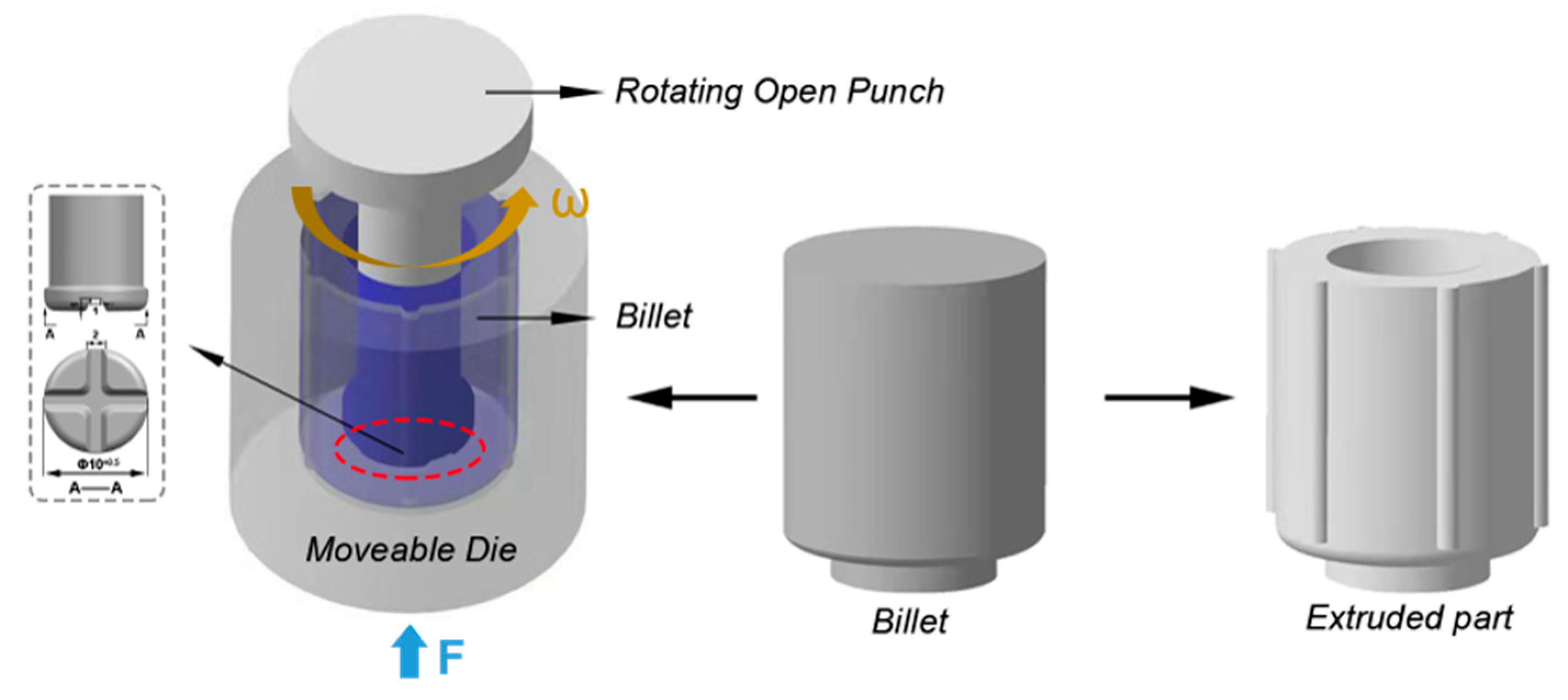
2. Materials and Methods

The initial material used in this experiment was extruded-7075 Al bar with T6 treatment. The specific chemical composition is shown in Table 1. In order to enhance the deformability and eliminate the effect of aging precipitates of the material, the extruded bar underwent solution treatment (T4) at 475 °C for 2 h, and was then rapidly cooled with water at room temperature. Several cylindrical rods with a diameter of 21 mm and length of 27 mm were prepared by electric spark cutting from the initial bar and used in the RBE experiment. Figure 1 and Figure 2a show the schematic illustration and specific die structure of the RBE process, respectively. In this experiment, the punch adopted an open structure, with a cross groove structure in a groove depth of 1 mm on the end surface. Due to the circumferential torsional deformation applied in RBE, six process ribs with Φ1 × 24 mm distributed along the circumference were set on the inner wall of the die to ensure the firmness of the billet in the extrusion. The RBE experiment was carried out using a Gleeble-3500 thermal simulation machine (DSI Inc., New York, NY, USA) equipped with torsion unit structure, as shown in Figure 2b. The specific RBE experiment was divided into three steps: (1) The moveable die was moved a certain distance (2 mm) to ensure that the billet filled the punch groove and the punch did not rotate during the process; (2) With the feed movement of the moveable die, the open punch began rotation; (3) When the moveable die was fed to the target stroke, the experiment ended and rapid cooling was implemented in the machine immediately. In this experiment, the deformation temperature was 410 °C, the total moveable die stroke was 20 mm, the moveable die feed speed was 0.05 mm/s, and the punch rotation speeds were 0, 0.0785, 0.1570, 0.2355, 0.3925, 0.785 rad/s, corresponding to the number of revolutions, respectively (N) = 0, 5, 10, 15, 25, 50 (0 N was defined as CBE processing). The specific parameters are shown in Figure 2c. Before extrusion, the billets and die were heated to the deformation temperature through resistance with the thermal simulation machine and kept warm for 10 min. The temperature variation of the billet during deformation was monitored by welding thermocouple wires to the bottom of the billet. Oil-based graphite was used as lubricant.
The microstructure of the extruded parts was investigated using an optical microscope (OM; A1 m, Zeiss Inc., Oberkochen, Germany) and scanning electron microscopy (SEM; SU5000, Hitachi Inc., Tokyo, Japan) equipped with electron backscatter diffraction (EBSD; EDAX Inc., Mahwah, NJ, USA). Samples for OM analysis were prepared by pre-grinding, mechanical polishing and etching using a solution of 2.5 mL HNO3, 1.5 mL HCl, 1 mL HF, and 95 mL H2O. For SEM and EBSD observation, the samples were first pre-grinded and polished, and then residual stress layer was removed using a LECO ion thinning instrument (Leica EMS-102, Wetzlar, Germany) with a voltage of 6.3 kV and electric current of 2.4 mA. The EBSD tests were conducted at the voltage of 20 kV, the tilt angle of samples was 70°, and the scanning step was 0.1–0.3 μm. The EBSD data were analyzed with orientation imaging microscopy (OIM) analysis v7.3 software (EDAX Inc., Mahwah, NJ, USA). The microhardness test was performed using a Vickers indenter with a load of 200 g as well as a loading time of 15 s. To ensure the reliability of the results, 5 indentations were measured under each condition.
Deform 3D-v11 software (SFTC Inc., Columbus, OH, USA) was used for FEM simulation analysis of CBE and RBE deformation. In the simulation, the die was set as a rigid body, and the billet of 7075 Al alloy was set as an elastic–plastic model (the specific material parameters are shown in Table 2). The simulated processing parameters were consistent with the actual deformation parameters. The friction model was considered as shear friction, and the friction factor was set at 0.3, as frequently used in lubricated thermal deformation.

3. Results and Discussion

3.1. FEM Analysis

In order to clarify the basic deformation characteristics and differences between CBE and RBE deformation, Figure 3 shows the FEM simulation results of the billet after CBE and RBE with the tracking results of the selected nodes of interest. The basic features of CBE deformation are as follows, a punch pushes the bottom material to produce quasi-upsetting deformation, promoting the flow of metal to the gap between the punch and the die, eventually forming the wall of the part. In this process, the material also experiences a certain degree of shear deformation when it flows through the corner of the punch. It can be observed that upsetting deformation during CBE provided an uneven deformation mode. Due to the strong frictional resistance between the punch and billet end surface, a dead deformation region formed in the center of the billet top (Figure 3b), which greatly limited metal flow toward the wall. Moreover, the outer metal surface in this region produced a certain resistance to the inner metal flow. Along the height direction, the middle section of the billet was the region of primary deformation, but showed a disadvantage of lower strain, which may lead to inadequate microstructure refinement of materials. Concerning the selected tracking nodes, it can be observed that the movement of the nodes (P1, P4) in the center of the billet after deformation was limited. With the selected nodes moved to the outside and the bottom, the metal fluidity was enhanced, but the overall strain amplitude remained at a lower level. In contrast, RBE deformation combines compressive and torsional deformation into a new SPD mode by imposing extra circumferential rotation to the punch. Due to the rotary movement of the punch, the friction resistance between the billet end surface and punch will be extensively transformed into an effective shear force, thus greatly eliminating the dead deformation region in the billet top. From the selected nodes, it can also be seen that compared with CBE deformation, RBE deformation promoted greater flow of the top metal surface of the billet, particularly the metal in the area around the middle wall (Figure 3c). Moreover, the comprehensive effects of compressive and torsional deformation greatly improved the overall strain level of the material. From the strain distribution, it can be observed that the dead deformation and deformation region of the billet during the RBE process merged into one region, and the strain level was extensively improved, which is conducive to the preparation of ultra-fine grained materials with high angle grain boundaries and reduced anisotropy. However, it was noted that as the billet moved away from the punch’s impact region, the strain level of the RBE extruded part decreased to a certain extent, showing the characteristics of a gradient distribution. The results indicated the effects of torsional and compressive deformation during RBE were inevitably reduced as the action of the punch weakened.
The FEM results of the effective strain distribution and average effective strain variables of RBE parts under a different number of revolutions (N) are shown in Figure 4. It can be seen that the average effective strain increases with an increase of N. The simulated average effective strain could be tremendously increased from 0.76 of the CBE to 9.54 of the RBE at 50 N through a severe torsional deformation. Moreover, it can be seen that with an increase of N, the plastic deformation area of the extruded part extended from the inside to the outside to a certain extent, indicating that an increase of N per unit time also increased the action range of the punch and thus the metal flow was further promoted. This will be confirmed in the Section 3.2 on microstructure characteristics.

3.2. Microstructure Characteristics

3.2.1. Initial Microstructure

Figure 5 showed the microstructure and EDS results of T4-7075 Al alloy. After T4 treatment, the extruded 7075 Al alloy showed a typical extruded fiber structure, mainly composed of elongated deformed grains that were large in size, with some fine dynamically recrystallized(DRXed) grains distributed around their boundaries. In addition, some coarse block-shaped phases were left on the matrix and distributed along the initial extrusion direction. SEM and EDS analysis clearly revealed that these massive compounds were mainly enriched in Al, Fe and a small amount of Cu. Due to the inevitable presence of Fe and other impurities in alloy melting, some studies have investigated the presence of a high melting point Fe-rich phase in Al alloys [20,21,22]. The EDS analysis showed that the Fe atomic weight of the observed insoluble Fe-rich compounds in the extruded 7075 bar was roughly 10%, but also contained a small amount of Cu, roughly 2.6%. In addition, a small amount of Mg–Si phase was found on the Al matrix, but the distribution number was extremely low. The Mg–Si compound was generally recognized as Mg2Si phase in Al alloys [21].

3.2.2. Microstructure after CBE and RBE

In order to reveal the metal flow characteristics of the materials with greater clarity during CBE and RBE, and to confirm the FEM results, a macro OM observation on the cross sections of both extruded parts was conducted, with the results shown in Figure 6. The wall region is the final position of metal flow for the extrusion part. The metal in the wall region of the CBE part essentially retained its original extruded fiber structure, and there was a certain range of deformation region that occurred on the inner side, with a low degree of microstructure refinement. However, there was a notable microstructure refinement on the inner side of the wall of the CBE (25 N) part, and the refinement amplitude decreased as it approached the outer wall, showing a gradient structure. It can be seen from the OM image of the earlier deformation stage (I) intercepted at a higher multiple that the metal in the dead deformation region of the CBE part retained the initial microstructure. In the upsetting region, the metal streamline was bent and flowed to the wall at an angle of around 45° with the movement of the die. Moreover, when the inner metal flowed through the corner of the punch, it underwent a certain shear deformation with the microstructure clearly refined, however, the overall refinement level remained insufficient. Due to the gradient distribution of the torsional and compressive stress, the bottom deformation characteristics of RBE parts showed a gradient structure from top to bottom. By applying circumferential rotation of open punch, it can be observed that the RBE deformation greatly altered the dead deformation zone between the billet surface and the punch into a severe deformation zone, where the initial elongated grains were replaced by complete fine DRXed grains (I). In the deformation zone II near the punch, the compressive and torsional deformation promoted the compression of the initial metal streamline into a transverse fine fiber or equiaxed structure, accompanied by significant DRX. In the deformation zone III located far from the punch, the initial streamline was flattened with a lower DRX degree due to the weakening of compression–torsion stress. Eventually, the metal in different deformation regions flowed into the wall of the part leading to a gradient microstructure distribution of the wall. In addition, it can be noted that in the wall of CBE part, the inner deformation region was weakened as it was in close proximity to the top section of the part (IV), which related to lower initial strain levels at the earlier extrusion stage due to the lack of back stress. However, the non-uniformity of deformation in the wall region of the RBE part along the height direction was notably weakened. This phenomenon can also be confirmed by the metal flow of selected nodes from Figure 3 (P1, P4). Compared with CBE deformation, it can be seen that RBE promoted the flow of metal at the top of the billet to the wall at the initial extrusion stage while the effective strain level simultaneously improved due to the addition of torsional deformation. As a result, this greatly promoted the microstructure refinement at the top of the part along the height direction and eventually improved the deformation heterogeneity.
It can be noticed that regardless of the CBE or RBE deformation, the main deformation region of the parts concentrated on the inner side, while there was no obvious microstructure refinement on the middle and outer side. As previously mentioned, this was related to the decrease of compressive and torsional stress in the material away from the punch, and was also greatly affected by the deformation ratio (the ratio of punch diameter to billet diameter), acting on the effective strain level and distribution. In our previous research on AZ80 Mg-alloy CBE shells with a wall thickness of 16 mm and outer diameter of 200 mm (deformation ratio was ~0.85), it was shown that although the wall of the extruded part displayed non-uniformity, the middle and outer sides were deformed to varying degrees [23]. Due to the influence of maximum loading (2 tons) of the thermal simulation testing machine, the deformation ratio of this CBE and RBE experiment was only around 0.47. In addition, the torsional pressure of the RBE experiment could not achieve the extremely high hydrostatic pressure similar to the HPT process in a laboratory scale with a smaller sample size [24], which functions as the microstructure refinement range. Therefore, further die structure designs will be the focus of our future work, and the current work was carried out mainly to reveal the effects of RBE and deformation parameters on the deformation characteristics and microstructure of the 7075 Al alloy.
In order to clarify the influence of the compression–torsion deformation mode and the N on the deformation degree and microstructure of the extruded parts, the main deformation regions at the bottom and at the wall of the extruded parts with different N were observed, and the results shown in Figure 7 and Figure 8, respectively. Figure 7 shows the low-magnification OM microstructure of the bottom of the extruded parts. The bottom and top of the CBE part was an un-deformed region. With an increase in N, came an increase in the refinement range of the microstructure at the bottom of RBE, indicating that increasing N per unit time brought not only greater strain variables, but also expanded the deformation amplitude, which is consistent with the results of FEM simulation. Due to the presence of strain gradient, the overall DRX level essentially decreased from top to bottom of the parts. It can be observed for 5 N and 10 N parts with relatively lower strain levels, that the top ends retained some deformed regions. Moreover, it can be noticed that due to the distribution differences of deformation torque in addition to the resistance of the outer metal to the inner metal surface, the edge of the top end part was better than the center position to be preferentially refined. As N increased from 5 to 10 and 15, the top region was gradually refined from the edge to the center, with the area of dead deformation region greatly reduced. When N exceeded 15, the top grains of parts were fully refined into fine DRXed grains.
Figure 8 shows the low magnification OM microstructure of the wall of extruded parts under different N. Refer to the macro metal flow in Figure 6, the microstructure of the wall region inherited the characteristics of the bottom. The deformed wall region of the CBE part was mainly characterized by the deformed structure caused by the upsetting deformation at the bottom, and a thin fine DRXed layer appeared in the inner wall due to shear deformation applied on the punch corner. The entire inner wall region of CBE parts were refined into fine DRXed grains. With continuous expansion to the outer wall, the degree of grain refinement decreased with decreasing strain amplitude, which was manifested as the transition region composed of fine fiber structure and DRXed grains. It can be seen that with an increase in N, the DRXed regions extended outward. When N increased to 50, the range of fine-grained regions reached roughly 1100 μm, compared to roughly 350 μm at 5 N.
To further reveal the grain refinement ability and microstructure of the material after RBE, Figure 9, Figure 10 and Figure 11 showed inverse pole figure (IPF) coloring maps, corresponding kernel average misorientation (KAM) and grain size distribution histograms of typical regions from the inner wall of extruded samples obtained by EBSD analysis. Using OIM software, we defined the range of low angle grain boundary (LAGB) as 3–15°, and the high angle grain boundary (HAGB) as greater than 15°. Grain orientation spread (GOS) was applied to distinguish between DRXed and non-DRXed grains of the tested samples [25,26], where we defined GOS values of less than 1° as indicative of DRXed grains. The available KAM value in this study was considered as 1–3° (KAM values less than 1° were considered machine errors, and values greater than 3° were identified as LAGBs/Sub-GBs).
The CBE microstructure of the selected region retained the initial extruded fiber structure and was accompanied by obvious dynamic recovery (DRV) with an abundance of LAGBs, but in some regions, the elongated deformation grains were also refined into some coarse DRXed grains and fine DRXed grains. The average misorientation angle (MA) in CBE sample was statistically around 22.8° with the existence of high proportion of LAGBs. It can be seen that as N increased, the extruded fiber structure of RBE parts was gradually replaced by DRX structure with average MA obviously increased and LAGBs rapidly reduced. From the corresponding KAM distributions (Figure 10), the dislocation density of the RBE samples was lower than that of the CBE samples, and exhibited a slight decrease with an increase in N, probably due to the more sufficient DRX continuously depleting the dislocation structure of the material. The percentage of DRX significantly increased from ~42% at 5 N to ~90% at 50 N, and the grain size of DRXed grain was maximally refined to ~1.2 μm at 25 N with the corresponding average grain size refined to ~1.3 μm. However, when N reached 50, the DRXed grained size and average grain size increased slightly, ~1.3 and ~1.4 μm, respectively. It is well known that temperature and strain rate as two key parameters in thermomechanical deformation, play a vital role in influencing the size of DRXed grains. In addition, this relationship can be represented by the classical Zener–Hollomon parameter [27]:
Z =   ε ˙ exp Q RT ,
where, ε ˙ is the strain rate, Q is the activation energy for lattice diffusion of Al, R is the gas constant, and T is the deformation temperature. DRXed grain size and the Z parameter can be further expressed as [28]:
lnZ + mlnd DRX = lnA
where m is the exponent and A is a constant. The increase of N per unit time significantly improved the effective strain rate, promoting the reduction of DRXed grain size. However, it can be inferred that the severe torsional deformation also inevitably accelerated the rise of local temperature. Although the torsional velocity increased from 0.3925 rad/s at 25 N to 0.785 rad/s at 50 N, the inevitable temperature rise caused by severe deformation may have decreased the Z parameter, and thus contributed to the growth of DRXed grains.
Figure 12 showed the SEM microstructure of the inner wall of extruded samples under different N (the test position was ~0.5 mm away from the inner wall). As previously observed, a large number of insoluble banded Fe-rich phases were retained in the initial state. After CBE, these banded phases remained preserved in the wall. However, as the initial fiber structure was refined under the action of severe deformation by RBE, the phase structure and distribution of the material were also greatly changed. A large number of phase particles of different sizes and morphologies were observed to be distributed in the RBE samples, and the distribution density increased to a certain extent with an increase of N. It is not difficult to identify that the large bulk phase particles in the matrix were the initial residual Fe-rich phases, while the finer dispersed phase particles could be considered as the mixture of further fragmented insoluble Fe-rich phases and possible new precipitates. Evidently, as N increased, the refinement level of insoluble Fe-rich phases also increased. In addition, it was noted that when N reached 50, a few microcracks appeared in the matrix. In order to further explore the phase evolution during RBE deformation, we observed the microstructure of the earlier extrusion stage, i.e., the deformation zone II at the bottom of RBE–25 N part in Figure 6, as shown in Figure 13. It can be seen that numerous phase particles had already appeared at this stage and distributed laterally along the metal streamline. Under severe plastic deformation, the insoluble Fe-rich phases were separated and fragmented. The higher magnification SEM images clearly showed that while the Fe-rich phases were broken, a large number of precipitated particles concurrently appeared in the DRXed grain regions of different sizes. The EDS results in Figure 13c further revealed that the residual Fe-rich phase particles could be refined to ~1–3 μm at this stage. The size distribution of fine dispersed precipitates ranged widely, ~0.05–1.5 μm. The EDS mapping scan of new precipitated phase particles with larger size clearly showed they were enriched with Mg and Zn elements, which could be identified as MgZn2 phase [21].
Previous studies have revealed that small size phase particles could be continuously precipitated from the matrix of alloy during thermomechanical deformation, which typically referred to dynamic precipitation [29]. Different from static precipitation, dynamic precipitation is not only related to processing temperature, but also strongly dependent on plastic deformation. RBE deformation through severe torsional deformation imposed during extrusion would promote strong dislocation accumulation in the matrix, which provided a favorable position for phase nucleation. At the same time, these dislocations would also output solute atoms to high-density dislocation entanglements at high speed, so that they reached higher saturation in a short time, and eventually accelerated the nucleation and growth of phase particles [30]. Moreover, the evolution of phase particles during deformation would have a certain impact on DRX. It was reported that when the size of phase particles was fine enough, their distribution at the grain boundary (GB) could become an obstacle to GB migration through the pinning effect [28]. As continuous plastic deformation occurred during RBE, some dislocations would rearrange and evolve into sub-grain boundaries (sub-GBs) and new GBs. In this process, the continuous nucleation and growth of new phase particles at these dislocations contributed to their distribution at GBs. Due to their small size and high density distribution of these particles, they could become an obstacle to the migration of GB, and then inhibit the growth of fine DRXed grains by the pinning effect.

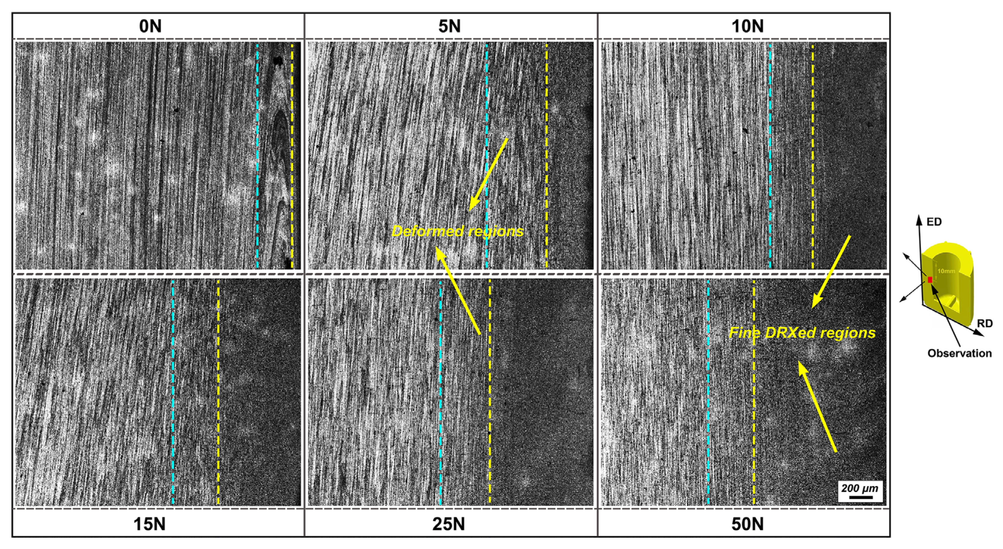
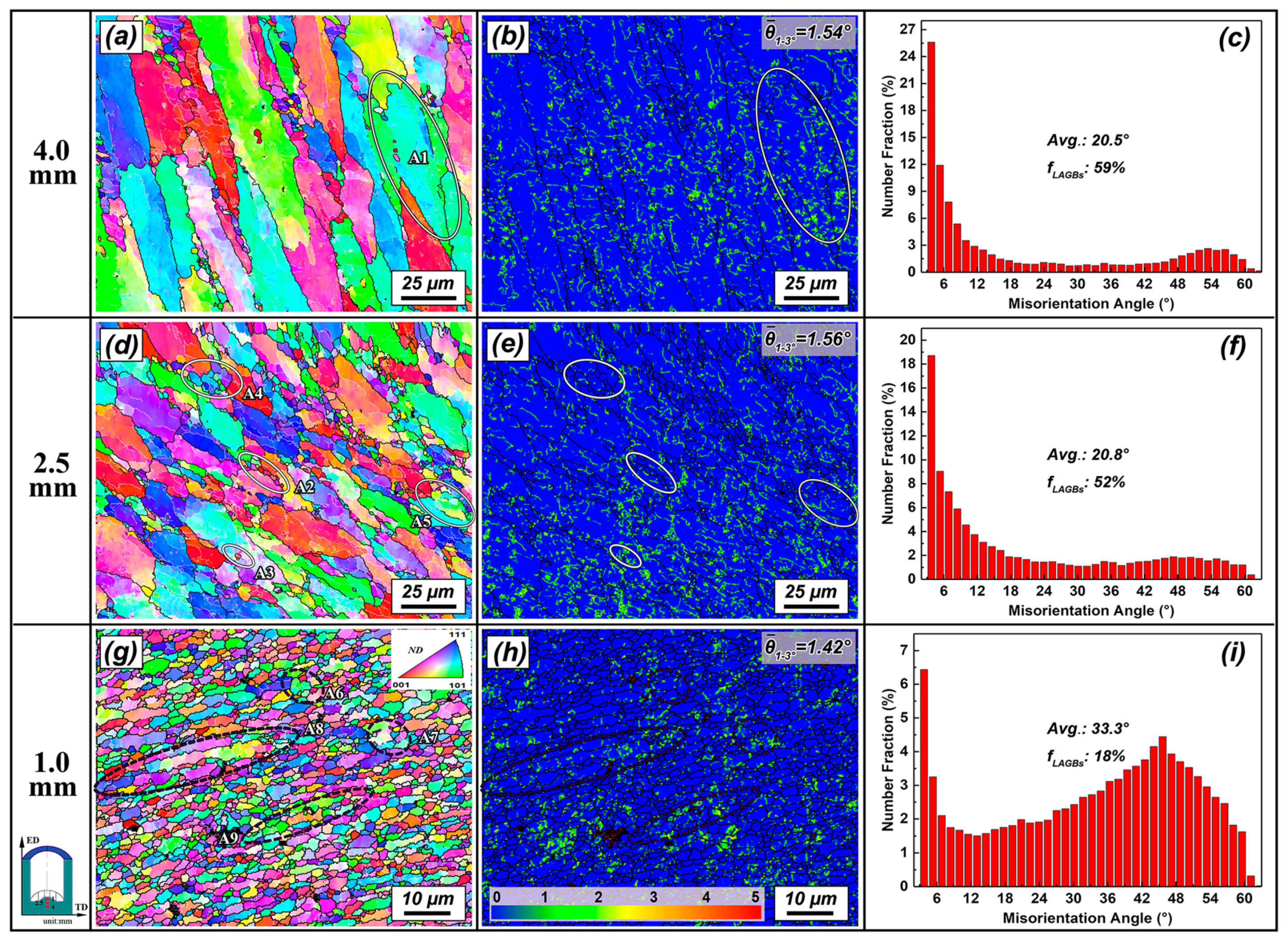
3.2.3. Microstructure Evolution during RBE

The RBE process exhibited a strong microstructure refinement capability for the materials by applying severe compression–torsion deformation. To clarify the microstructure revolution and grain refinement mechanism in RBE, Figure 14 shows IPF coloring maps with typical deformed regions selected at 1 mm, 2.5 mm and 4 mm from the top of the RBE (25 N) billet, with the corresponding KAM and MA distribution histogram obtained by EBSD analysis.
Figure 14a presented the IPF coloring map of the deformation region at 4 mm from the top of the billet. Due to the gradient distribution of the effective strain, the effect of torsional stress in this region was insufficient. The initial extruded fiber structure was mainly flattened under compressive stress. It was observed that a large number of LAGBs were distributed within the deformed grains, and the KAM map revealed that a large amount of dislocations distributed simultaneously. It is known that Al as a typical metal with high-level stacking fault energy, making it difficult to achieve full DRX during thermal deformation due to the rapid DRV process [31]. In Al, DRV mainly includes the elimination and rearrangement of opposite sign dislocations caused by dislocation cross slip and climb. The formation of sub-structures and DRXed grains is closely related to dislocation rearrangement and subsequent dynamic polygonization, which provides a prerequisite for continuous dynamic recrystallization (CDRX). The typical DRX characteristics at this stage can be seen from the higher magnification image of the region A1 in Figure 14a, as shown in Figure 15. Under plastic deformation, the grains in the deformation region were flattened and accompanied by a significant variation in crystal orientation (Figure 15a). The line profile of MA and inserted three dimensional face-centered cubic (FCC) crystal cells along the line L1 showed that there was a large orientation gradient of ~13° along the length of ~35 μm present in the matrix with strong lattice distortion. According to the orientation differences, the selected deformed region could be divided into three sub-grain parts, P11, P12 and P13 (Figure 15d). Interiorly, some fine sub-grains were formed and developed into DRXed grains via the transformation of LAGBs to HAGBs, showing the characteristics of CDRX. It should be considered that the appearance of large-size sub-grains would cut the matrix grains, and finally promote the refinement of the deformed grains into different parts.
Figure 14d showed the IPF coloring map of the deformation region at 2.5 mm from the top of the billet. As the metal approached the punch, the compression–torsion stress increased, and the metal deformed in the previous stage could produce a more obvious plastic deformation after flowing into this stage. The deformed grains were continuously flattened as the range of grain refinement increased in this stage. Compared with the initial stage, the KAM distribution revealed that the dislocation density increased due to more severe plastic deformation. At the same time, the proportion of LAGBs decreased and the average MA increased, indicating that more pronounced CDRX occurred via the evolution of LAGBs to HAGBs. The DRX behavior at this stage showed following three basic characteristics: (1) The formation of large-size DRXed grains through the emergence and transformation of large-size sub-grains in the initial deformed grains; (2) New DRXed grain appearance at the boundary and inside large deformed grains due to local strain accumulation (A2 and A3); (3) The newly formed large-size DRXed grains were gradually refined to fine DRXed grains under continuous deformation through the dominant CDRX (A4 and A5). These eventually greatly promoted grain refinement in this stage.
Figure 14g showed the IPF coloring map of the deformation region at 1 mm from the top of billet. The stronger compression–torsion deformation promoted the transverse flattening of the metal streamline from previous stages, accompanied by significant grain refinement. The microstructure was characterized by a mixed grain structure composed of DRXed grains and deformed grains with fine fiber structure. Due to the development of a large number of DRXed grains, the proportion of LAGBs decreased to 18% and the average MA increased to 33.3° with the KAM value greatly reduced. There were two main grain refinement behaviors in this stage: (1) The large-size DRXed grains formed in the earlier stage were refined through CDRX under continuous strain (A6 and A7); (2) The large, deformed grains were flattened laterally and transformed into fine fiber structure, and continuously refined into new DRXed grains (A8 and A9). To further reveal the typical DRX behavior at this stage, Figure 16 showed the deformation characteristics of elongated deformed grains intercepted from A8 in Figure 14g. Under the severe deformation, the interior of deformed grains developed into a banded grain structure consisted entirely of fine sub-grains with MA of 8–11° (Figure 16b). The boundaries of deformed grains had become serrated and in some regions they were refined to the entire or one-half thickness of sub-grains. It is noted that when the deformed grains became thin enough, the DRXed grains evolved from sub-grains would pinch them into different parts. Such DRX behavior could be considered as a typical feature of geometric dynamic recrystallization (GDRX) [31]. It was revealed the original large grains had a tendency to be flattened (compression stress) or elongated (tension or torsion stress) during large plastic deformation, and their boundaries would become serrated with the formation of sub-grain. As the GB area per unit volume rapidly increased, the sub-grain facets formed by the original GB increased remarkably. Finally, when the original grain thickness was reduced to two sub-grain’s size, the GBs made contact with each other, resulting in the crushing, pinching off the original grains, and formation of fine DRXed grains with HAGBs, i.e., GDRX phenomenon [32,33]. In general, GDRX is considered prone to large strain deformation, while CDRX usually begins at a lower strain amplitude. Blum et al., [34] reviewed the occurrence of GDRX phenomenon in the large-strain torsion deformation of AA5083 alloy. Yu et al., [33] also considered that GDRX was induced by pinching off the compressed or elongated initial grains caused by large strain. As a result, when the material was distanced far from the active region of open punch during RBE, the grain refinement by CDRX promoted the refinement and slitting of large, deformed grains. With the continuous strengthening of compression–torsion stress, the deformed grains flattened into fine fiber structure and GDRX simultaneously appeared, greatly accelerating the DRX process in the later stage.

3.3. Microstructure and Properties after Heat Treatment

It is known that 7075 Al alloy as a typical heat-treated alloy, that aging precipitates are the key to improve its properties. As previously observed, a large number of dynamic precipitated particles occurred in the matrix after RBE. However, the size of these phase particles was much larger than the typical aging precipitated particles in Al–Zn–Mg–Cu alloys, and greatly consumed the solute elements in the matrix. To dissolve these phase particles and clarify the effects of grain refinement and precipitation strengthening on the properties of extruded parts, we selected the 25 N sample with the finest grain size conducted a short-time annealing at 475 °C for 30 min and subsequent artificial aging at 120 °C for 24 h (T6). Figure 17 shows the annealed microstructure of the 25 N sample (the test position was 0.5 mm away from the inner wall).
After annealing, the grain structure of the sample occurred with clear static recovery and recrystallization with the equiaxed grains developed and the intracrystalline dislocations were greatly consumed. It is noted that although the grain size maintained a relatively fine distribution, they inevitably increased to ~2.7 μm compared with ~1.3 μm in extruded state. SEM showed that all dynamic precipitated particles had fully dissolved into the matrix after short-time annealing, while the refined Fe-rich phases were preserved. Since these insoluble Fe-rich phases belong to brittle hard and hard compounds, when their size is relatively large, they are prone to becoming crack sources in plastic deformation. It was revealed that refining the Fe-rich phase through SPD method was conducive to improving the toughness and fatigue resistance of the Al alloy. An increasing strength and ductility was observed in a brittle Al-5–Fe alloy processed by ECAP due to the refinement of Fe-rich particles [35]. Sha et al., [20] also revealed that after 8 passes of ECAP, the average size of insoluble Fe-rich phases in AA7136 alloy could be effectively refined to ~131 nm, compared with ~757 nm in the initial extruded alloy. Compared with the coarse banded insoluble Fe-rich phases remaining in the initial extruded bar, these type of phases showed significant size refinement and distribution improvement after RBE, thus being conducive to the improvement of the potential fracture properties of the material.
Figure 18 shows the Vickers microhardness distribution of the initial T6-extruded rod, the T4-extruded rod (the initial experimental state), the fine grain region of RBE-25 N and T6-RBE (25 N) part. Compared with the T4-extruded rod (~95 HV), the microhardness of the extruded part was significantly improved after RBE treatment due to significant grain refinement and hardening of dynamic precipitated particles. The microhardness of the fine grain region at different positions along the inner side was distributed between ~101–106 HV. It is noted that the hardness of the wall region was slightly lower than that of the bottom region, which could be related to the dislocation accumulation caused by more severe compression–torsion deformation at the bottom. After T6 heat treatment, the hardness of the fine grain region of the part had effectively increased to ~192–197 HV and without significant distribution difference in different positions. Compared with the T6-extruded state with a value of ~180 HV, the improvement of properties showed that grain refinement combined with precipitation strengthening could potentially improve the mechanical properties of extruded parts. However, due to the size limitation of the currently prepared samples and the limited range of fine grain region caused by the relatively low deformation ratio, the effect of RBE treatment on the overall properties of the material, including the connection between the refinement of the insoluble Fe-rich phase and the fracture properties, had not been further revealed. Therefore, further work will be carried out on die design, extruded part size and mechanical properties research.

4. Conclusions

7075 Al alloy shell parts were successfully prepared by employing a new rotating backward extrusion (RBE) method with different number of revolutions (N = 5, 10, 15, 25, 50) at 410 °C. The effects of the RBE process on grain refinement, precipitates, and properties of extruded parts were reported and the deformation characteristics were compared with conventional backward extrusion (CBE). The main conclusions can be drawn as follows:
(1)
Compared with CBE, due to the addition of severe torsional deformation under open punch, the RBE process eliminated the dead deformation zone at the bottom of the shell part, and greatly improved the deformation uniformity and the comprehensive effective strain level of the material. The overall strain level of the extruded parts continuously weakened from the inner wall to the outer wall due to the decrease of the compression–torsion stress.
(2)
In RBE deformation, an increase in N greatly improved the grain refinement ability and grain refinement range of the extruded parts. The microstructure observation of the inner wall of the extruded samples revealed that the grain refinement range could immensely increase from roughly 350 μm at 5 N to approximately 1100 μm when N reached up to 50. The average grain size was maximally refined to around 1.3 μm at 25 N, compared to roughly 13.7 μm in the CBE sample.
(3)
Due to the severe compression–torsion deformation, RBE strongly promoted the refinement of massive insoluble Fe-rich phases that remained in the initial extruded bar. As N increased, the fragmentation degree of insoluble Fe-phases also increased in a continuous manner. At the same time, a large number of Mg–Zn2 particles were dynamically precipitated from the matrix, acting as an obstacle to grain boundary migration and grain growth by the pinning effect.
(4)
The grain refinement of the 7075 Al alloy under RBE was related to the comprehensive effects of continuous dynamic recrystallization (CDRX) and geometric dynamic recrystallization (GDRX). At the initial stage with lower strain levels, CDRX promoted the segmentation and refinement of deformed grains into smaller parts. With the gradual increase of compression and torsion stress, the deformed grains were flattened into fine fiber structures, and the crushing and pinching off of these grains via GDRX promoted grain refinement in the final stage.
(5)
The RBE process greatly improved the properties of the material. The study of the RBE–25 N part showed that short-time annealing could effectively dissolve the dynamic precipitated particles remaining after extrusion. After annealing, the average grain size of the extruded part increased to approximately 2.7 μm. After T6 treatment, the microhardness of the fine grain region for the part could be increased to ~192–197 HV, compared with ~180 HV in the initial extruded state.

Author Contributions

Conceptualization, S.L. and F.Y.; methodology, S.L., R.W., N.G. and Z.W.; software, S.L., F.Y. and Z.W.; investigation, S.L., F.Y. and W.X.; writing (original draft preparation), S.L. and N.G.; writing (review and editing), S.L., F.Y., N.G. and K.X. All authors have read and agreed to the published version of the manuscript.

Funding

This research was funded by Natural Science Foundation of Ningbo, China (Grant number 2021J231) and Science and Technique Plans of Longquan City, China (Grant number 2021KJ-012).

Data Availability Statement

The data presented in this study are available on request from the corresponding author. The data are not publicly available due to privacy or ethics.

Conflicts of Interest

The authors declare no conflict of interest.

References

  1. Aryshenskii, E.; Lapshov, M.; Konovalov, S.; Hirsch, J.; Aryshenskii, V.; Sbitneva, S. The Casting Rate Impact on the Microstructure in Al–Mg–Si Alloy with Silicon Excess and Small Zr, Sc Additives. Metals 2021, 11, 2056. [Google Scholar] [CrossRef]
  2. Pang, J.J.; Liu, F.C.; Liu, J.; Tan, M.J.; Blackwood, D.J. Friction stir processing of aluminium alloy AA7075: Microstructure, surface chemistry and corrosion resistance. Corros. Sci. 2016, 106, 217–228. [Google Scholar] [CrossRef]
  3. Bachir Bouiadjra, B.A.; Mohammed, S.M.A.K.; Benyahia, F.; Albedah, A. Fatigue Behavior of Al 7075-T6 Plates Repaired with Composite Patch under the Effect of Overload. Metals 2021, 11, 2025. [Google Scholar] [CrossRef]
  4. Duan, Y.; Tang, L.; Xu, G.; Deng, Y.; Yin, Z. Microstructure and mechanical properties of 7005 aluminum alloy processed by room temperature ECAP and subsequent annealing. J. Alloy. Compd. 2016, 664, 518–529. [Google Scholar] [CrossRef]
  5. Azarniya, A.; Taheri, A.K.; Taheri, K.K. Recent advances in ageing of 7xxx series aluminum alloys: A physical metallurgy perspective. J. Alloy. Compd. 2019, 781, 945–983. [Google Scholar] [CrossRef]
  6. Zhao, X.; Li, S.; Zheng, Y.; Liu, Z.; Chen, K.; Yu, J.; Zhang, Z.; Zheng, S. The microstructure evolution, texture weakening mechanism and mechanical properties of AZ80 Mg alloy processed by repetitive upsetting-extrusion with reduced deformation temperature. J. Alloy. Compd. 2021, 883, 160871. [Google Scholar] [CrossRef]
  7. Ebrahimi, M. Fatigue Behaviors of Materials Processed by Planar Twist Extrusion. Metall. Mater. Trans. A 2017, 48, 6126–6134. [Google Scholar] [CrossRef]
  8. Dong, J.; Gao, N.; Chen, Y.; Cao, L.; Song, H.; Fröck, H.; Milkereit, B.; Starink, M.J. Achieving ultra-high strength of Al-Cu-Li alloys by the combination of high pressure torsion and age-hardening. Mater. Sci. Eng. A 2022, 832, 142504. [Google Scholar] [CrossRef]
  9. Ebrahimi, M.; Shamsborhan, M. Monotonic and dynamic mechanical properties of PTCAE aluminum. J. Alloy. Compd. 2017, 705, 28–37. [Google Scholar] [CrossRef]
  10. Ebrahimi, M.; Djavanroodi, F.; Tiji, S.A.; Gholipour, H.; Gode, C. Experimental Investigation of the Equal Channel Forward Extrusion Process. Metals 2015, 5, 471–483. [Google Scholar] [CrossRef] [Green Version]
  11. Kim, Y.G.; Ko, Y.G.; Shin, D.H.; Lee, S. Effect of equal-channel angular pressing routes on high-strain-rate deformation behavior of ultra-fine-grained aluminum alloy. Acta Mater. 2010, 58, 2545–2554. [Google Scholar] [CrossRef]
  12. Ikumapayi, O.M.; Oyinbo, S.T.; Bodunde, O.P.; Afolalu, S.A.; Okokpujie, I.P.; Akinlabi, E.T. The effects of lubricants on temperature distribution of 6063 aluminium alloy during backward cup extrusion process. J. Mater. Res. Technol. 2019, 8, 1175–1187. [Google Scholar] [CrossRef]
  13. Wang, H.; Gao, L.; Chen, M. Hydrodynamic deep drawing process assisted by radial pressure with inward flowing liquid. Int. J. Mech. Sci. 2011, 53, 793–799. [Google Scholar] [CrossRef]
  14. Wang, S.; Xu, W.; Shao, B.; Yang, G.; Zong, Y.; Sun, W.; Yang, Z.; Shan, D. Process design and microstructure-property evolution during shear spinning of Ti2AlNb-based alloy. J. Mater. Sci. Technol. 2022, 101, 1–17. [Google Scholar] [CrossRef]
  15. Hosseini, S.H.; Abrinia, K.; Faraji, G. Applicability of a modified backward extrusion process on commercially pure aluminum. Mater. Des. (1980–2015) 2015, 65, 521–528. [Google Scholar] [CrossRef]
  16. Yu, J.; Zhang, Z.; Wang, Q.; Hao, H.; Cui, J.; Li, L. Rotary extrusion as a novel severe plastic deformation method for cylindrical tubes. Mater. Lett. 2018, 215, 195–199. [Google Scholar] [CrossRef]
  17. Kim, Y.H.; Park, J.H. Upper bound analysis of torsional backward extrusion process. J. Mater. Processing Technol. 2003, 143–144, 735–740. [Google Scholar] [CrossRef]
  18. Che, X.; Dong, B.; Wang, Q.; Liu, K.; Meng, M.; Gao, Z.; Ma, J.; Yang, F.; Zhang, Z. The effect of processing parameters on the microstructure and texture evolution of a cup-shaped AZ80 Mg alloy sample manufactured by the rotating backward extrusion. J. Alloy. Compd. 2021, 854, 156264. [Google Scholar] [CrossRef]
  19. Dursun, T.; Soutis, C. Recent developments in advanced aircraft aluminium alloys. Mater. Des. (1980–2015) 2014, 56, 862–871. [Google Scholar] [CrossRef]
  20. Sha, G.; Wang, Y.B.; Liao, X.Z.; Duan, Z.C.; Ringer, S.P.; Langdon, T.G. Microstructural evolution of Fe-rich particles in an Al–Zn–Mg–Cu alloy during equal-channel angular pressing. Mater. Sci. Eng. A 2010, 527, 4742–4749. [Google Scholar] [CrossRef]
  21. Zou, X.-l.; Yan, H.; Chen, X.-h. Evolution of second phases and mechanical properties of 7075 Al alloy processed by solution heat treatment. Trans. Nonferrous Met. Soc. China 2017, 27, 2146–2155. [Google Scholar] [CrossRef]
  22. Xu, D.K.; Rometsch, P.A.; Birbilis, N. Improved solution treatment for an as-rolled Al–Zn–Mg–Cu alloy. Part II. Microstructure and mechanical properties. Mater. Sci. Eng. A 2012, 534, 244–252. [Google Scholar] [CrossRef]
  23. Zhao, X.; Li, S.; Zhang, Z.; Gao, P.; Kan, S.; Yan, F. Comparisons of microstructure homogeneity, texture and mechanical properties of AZ80 magnesium alloy fabricated by annular channel angular extrusion and backward extrusion. J. Magnes. Alloy. 2020, 8, 624–639. [Google Scholar] [CrossRef]
  24. Straumal, B.B.; Kilmametov, A.R.; Baretzky, B.; Kogtenkova, O.A.; Straumal, P.B.; Lityńska-Dobrzyńska, L.; Chulist, R.; Korneva, A.; Zięba, P. High pressure torsion of Cu–Ag and Cu–Sn alloys: Limits for solubility and dissolution. Acta Mater. 2020, 195, 184–198. [Google Scholar] [CrossRef]
  25. Barrett, C.D.; Imandoust, A.; Oppedal, A.L.; Inal, K.; Tschopp, M.A.; El Kadiri, H. Effect of grain boundaries on texture formation during dynamic recrystallization of magnesium alloys. Acta Mater. 2017, 128, 270–283. [Google Scholar] [CrossRef]
  26. Wang, W.; Cui, G.; Zhang, W.; Chen, W.; Wang, E. Evolution of microstructure, texture and mechanical properties of ZK60 magnesium alloy in a single rolling pass. Mater. Sci. Eng. A 2018, 724, 486–492. [Google Scholar] [CrossRef]
  27. Jia, W.P.; Hu, X.D.; Zhao, H.Y.; Ju, D.Y.; Chen, D.L. Texture evolution of AZ31 magnesium alloy sheets during warm rolling. J. Alloys Compd. 2015, 645, 70–77. [Google Scholar] [CrossRef]
  28. Jiang, M.G.; Xu, C.; Nakata, T.; Yan, H.; Chen, R.S.; Kamado, S. High-speed extrusion of dilute Mg-Zn-Ca-Mn alloys and its effect on microstructure, texture and mechanical properties. Mater. Sci. Eng. A 2016, 678, 329–338. [Google Scholar] [CrossRef] [Green Version]
  29. Lang, Y.; Cai, Y.; Cui, H.; Zhang, J. Effect of strain-induced precipitation on the low angle grain boundary in AA7050 aluminum alloy. Mater. Des. 2011, 32, 4241–4246. [Google Scholar] [CrossRef]
  30. Guo, F.; Zhang, D.; Yang, X.; Jiang, L.; Pan, F. Strain-induced dynamic precipitation of Mg17Al12 phases in Mg–8Al alloys sheets rolled at 748K. Mater. Sci. Eng. A 2015, 636, 516–521. [Google Scholar] [CrossRef]
  31. Huang, K.; Logé, R.E. A review of dynamic recrystallization phenomena in metallic materials. Mater. Des. 2016, 111, 548–574. [Google Scholar] [CrossRef]
  32. Fan, X.H.; Tang, D.; Fang, W.L.; Li, D.Y.; Peng, Y.H. Microstructure development and texture evolution of aluminum multi-port extrusion tube during the porthole die extrusion. Mater. Charact. 2016, 118, 468–480. [Google Scholar] [CrossRef]
  33. Yu, P.; Wu, C.; Shi, L. Analysis and characterization of dynamic recrystallization and grain structure evolution in friction stir welding of aluminum plates. Acta Mater. 2021, 207, 116692. [Google Scholar] [CrossRef]
  34. Blum, W.; Zhu, Q.; Merkel, R.; McQueen, H.J. Geometric dynamic recrystallization in hot torsion of Al□5Mg□0.6Mn (AA5083). Mater. Sci. Eng. A 1996, 205, 23–30. [Google Scholar] [CrossRef]
  35. Stolyarov, V.V.; Lapovok, R.; Brodova, I.G.; Thomson, P.F. Ultrafine-grained Al–5 wt.% Fe alloy processed by ECAP with backpressure. Mater. Sci. Eng. A 2003, 357, 159–167. [Google Scholar] [CrossRef]
Figure 1. Schematic illustrations of rotating backward extrusion (RBE) process.
Metals 12 00227 g001
Figure 2. (a) The die structure, (b) experimental equipment, and (c) specific processing procedure and parameters for applied RBE method.
Metals 12 00227 g002
Figure 3. (a) The initial billet marked with selected nodes of interest, and effective strain distributions with tracking results for initial nodes under: (b) conventional backward extrusion (CBE) and (c) RBE (25 N).
Metals 12 00227 g003
Figure 4. Variation of average effective strain and strain distribution of the extruded samples with number of revolutions (N).
Metals 12 00227 g004
Figure 5. (a) Optical microscopy (OM) image, (b) backscattered scanning electron microscopy (SEM) image, and (c,d) corresponding energy-dispersive X-ray (EDX) results for the as-extruded T4-7075 Al alloy.
Metals 12 00227 g005
Figure 6. Macroscopic OM images of (a) CBE and (b) RBE (25 N) samples marked with highly magnified regions containing corresponding deformation characteristics (I, II, III and IV: the typical deformation region of CBE or RBE samples).
Metals 12 00227 g006
Figure 7. OM images of the bottom region of extruded samples selected from different N.
Metals 12 00227 g007
Figure 8. OM images of the inner wall region of extruded samples selected from different N.
Metals 12 00227 g008
Figure 9. Inverse pole figure (IPF) coloring maps of the inner wall region of extruded samples selected from different N.
Metals 12 00227 g009
Figure 10. Kernel average misorientation (KAM) distribution histograms in the inner wall region of extruded samples with different N based on electron backscatter diffraction (EBSD) statistics.
Metals 12 00227 g010
Figure 11. Grain size distribution histograms in the inner wall region of extruded samples with different N based on electron backscatter diffraction (EBSD) statistics.
Metals 12 00227 g011
Figure 12. Backscattered SEM images of the inner wall region of extruded samples selected from different N.
Metals 12 00227 g012
Figure 13. (a,b) Backscattered SEM images and (c,d) corresponding EDS results of the bottom deformed region of the RBE (25 N) sample.
Metals 12 00227 g013
Figure 14. EBSD results showing the microstructure evolution during different stages of RBE (25 N) sample: (a,d,g) IPF coloring maps, (b,e,h) corresponding KAM distribution maps and (c,f,i) misorientation angle (MA) distribution histograms.
Metals 12 00227 g014
Figure 15. The DRX behavior of the deformed region (A1) selected in Figure 14a: (a) IPF coloring map, (b) line profile of MA along the line L1 in (a), and corresponding (c) (111) pole figure and (d) inverse pole figure.
Metals 12 00227 g015
Figure 16. The DRX behavior of the deformed region (A4) selected in Figure 14g: (a) IPF coloring map, (b) line profile of MA along the line L2 in (a), and corresponding (c) (111) pole figure.
Metals 12 00227 g016
Figure 17. (a) IPF coloring map, (b) KAM map, (c) backscattered SEM image and (d) grain size distribution histogram of the annealed RBE (25 N) sample.
Metals 12 00227 g017
Figure 18. Vickers microhardness of T6-extruded bar, T4-extruded bar, RBE (25 N), and T6-RBE (25 N) samples.
Metals 12 00227 g018
Table 1. Chemical compositions of 7075 Al alloy (wt%).
ZnMgCuFeSiAl
5.1–6.12.1–2.91.2–2.0<0.4<0.5Bal.
Table 2. The specific parameters of 7075 Al alloy billet used in the simulation.
Material ParametersValues
Elastic modulus (GPa)71
Poisson’s ratio0.33
Height of billet (mm)27
Diameter of billet (mm)21
Mesh number of billet30,000
Minimum mesh edge length (mm)0.46
Publisher’s Note: MDPI stays neutral with regard to jurisdictional claims in published maps and institutional affiliations.

