Article

Modeling of the Effect of Secondary Orientation on the Micro Deformation Behavior of Ni-Based Single Crystal Superalloys

1
Beijing Engineering Research Center of Laser Technology, Beijing University of Technology, Beijing 100124, China
2
Institute of Laser Engineering, Faculty of Materials and Manufacturing, Beijing University of Technology, Beijing 100124, China
3
Advanced High Temperature Structural Materials Laboratory, AECC Beijing Institute of Aeronautical Materials, Beijing 100095, China
*
Author to whom correspondence should be addressed.
Metals 2022, 12(2), 217; https://doi.org/10.3390/met12020217
Submission received: 7 December 2021 / Revised: 1 January 2022 / Accepted: 21 January 2022 / Published: 24 January 2022
(This article belongs to the Topic Single-Crystal Ni-Based Alloys)

Abstract

:
In this paper, a supercell modeling of secondary orientation was established using 90 cubic mosaic units made up of γ’ phase embedded in γ matrix, in accordance with an actual structure of Ni-based single crystal superalloys (NSCS). The effects of secondary orientation on the deformation behavior and microstructure evolution of NSCS under uniaxial tensile were studied by a three-dimensional molecular dynamics (MD) simulation. Simulation results showed that secondary orientation had a significant effect on mechanical properties of NSCS, that is, a big fluctuation was found in tensile strength which dropped down almost 50% from a peak (corresponding to the secondary orientations of 18° and 45°) to a trough (those of 34° and 63°). Mechanisms of secondary orientation affecting the deformation behavior were further discussed systematically. The deformation of NSCS under uniaxial tensile was a process tending towards amorphization of microstructure, together with the dislocation formation, merging and break-up. On a micro viewpoint, this work for us will be useful to apprehend the tensile deformation conduct of NSCS.

1. Introduction

NSCS is the most commonly used material for turbine blades of advanced aero-engines today [1,2,3,4,5,6], and most single crystal turbine blades are produced by casting that entails controlling the growth direction of the principal stress axis [7]. Generally, the direction of the main stress axis is called primary orientation, which has a significant impact on the arm spacing of primary dendrites, creep properties or stress fracture life, etc. [8,9,10,11]. However, in most single crystal blades, the [100] orientation perpendicular to the [001] direction is neither specified nor controlled during the manufacturing process and can only be determined by measurement. Therefore, the [100] orientation of a single crystal blade becomes a random variable, which we call secondary orientation [7]. Each single crystal blade has a different secondary orientation [12,13,14]. It is important to strictly control these growth directions for NSCS, however, such complex factors as deviation of chemical composition in the micro scale, instability of the solidification process and so on lead to a departure from the original growth direction, causing poor performance of NSCS in service. The prediction and optimization of secondary orientation may be a potential way to further improve the mechanical properties of single crystal blades. However, most previous research only concentrated on the primary orientation, regardless of the influence of secondary orientation. Recent studies have shown that secondary orientation plays an important role on mechanism behavior. Zienkiewicz et al. [15] investigated the fatigue failure of NSCS turbine blades and concluded that the control of secondary and primary crystallographic orientations improves the fatigue resistance of turbine blades. Hou et al. [16] reported that the secondary orientation had a limited influence on the distributions of Mises stress and the maximum resolved shear stress. Arakere [17] and Getsov [18] observed that the secondary orientation had a pronounced effect on high cycle fatigue life and thermal mechanical properties. Wang et al. [19] further studied the effects of secondary orientations on thermal fatigue behavior of an NSCS turbine blade and found that fatigue cracks initiate from stress concentration regions which are affected by the secondary orientation. Yang et al. [20] studied tensile properties of three secondary orientations of [100], [120] and [110] for DD9 NSCS in the temperature range of 760–1100 °C, and showed that the effect of secondary orientation on tensile strength was remarkable. Zhai et al. [21] used the finite element method to study the maximum stress of the material with the change of secondary orientation. It was found that the secondary orientation of 45° has the lowest resolved shear stress, which may lead to higher strength of single crystal turbine blades. But, nowadays the effect of secondary orientation on the deformation behavior has not been clarified because it is not as easy to detect and control as the primary orientation.
Using a simulation instead of an experiment can greatly improve the efficiency of research [22,23,24,25,26]. Molecular dynamics (MD) simulation has the advantage of capturing dynamic deformation in real time and studying the microscopic deformation mechanisms at atomic scale, such as obtaining the micro-scale crack configurations and visualizing the corresponding producing process [25]. Zhu et al. [26] and Xiong et al. [27] have studied the interaction between matrix dislocation and interface mismatch dislocation network in NSCS by MD. While Shang et al. [28] used an embedded atom method (EAM) in MD simulation to study the plastic deformation mechanism at the interface of Ni/Ni3Al alloy with a pre-existing void under tensile loading. Bin et al. [29] further studied fatigue properties and the deformation mechanism of superalloys under a cyclic tension-and-compression load by MD simulations which provided some important information for understanding the fatigue mechanism of superalloys from the atomic point of view. Most above research has all shown that MD was an effective way to simulate the damage process. However, those MD models developed with NSCS were mainly based on a two-layer or a sandwich structure simulation [30,31], without considering the actual structure (γ’ phase embedded in γ matrix) characteristic of NSCS, leading to inaccurate mechanical properties and difficulty predicting the real deformation behavior.
In this paper, influences of secondary orientation on the tensile deformation behavior of NSCS were studied using MD simulations. A mosaic structure supercell model was developed consisting of 90 basic γ′/γ units with 152,010 atoms totally. Tensile properties, microstructure and dislocation evolution were then investigated systematically based on the model, and mechanisms of deformation and fracture were further analyzed at atomic scale. This work will be meaningful to understand the secondary orientation effection and deformation mechanism in NSCS.

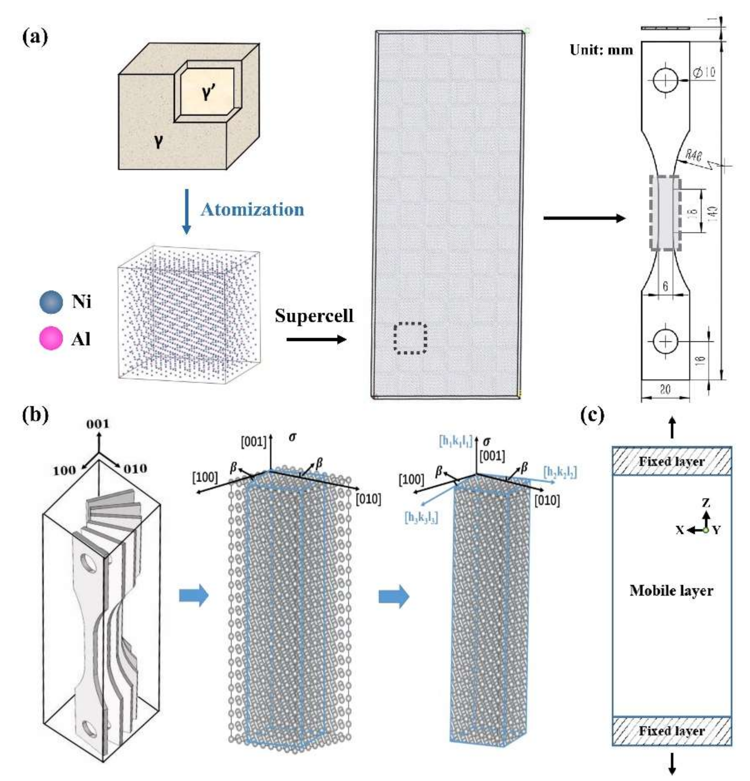
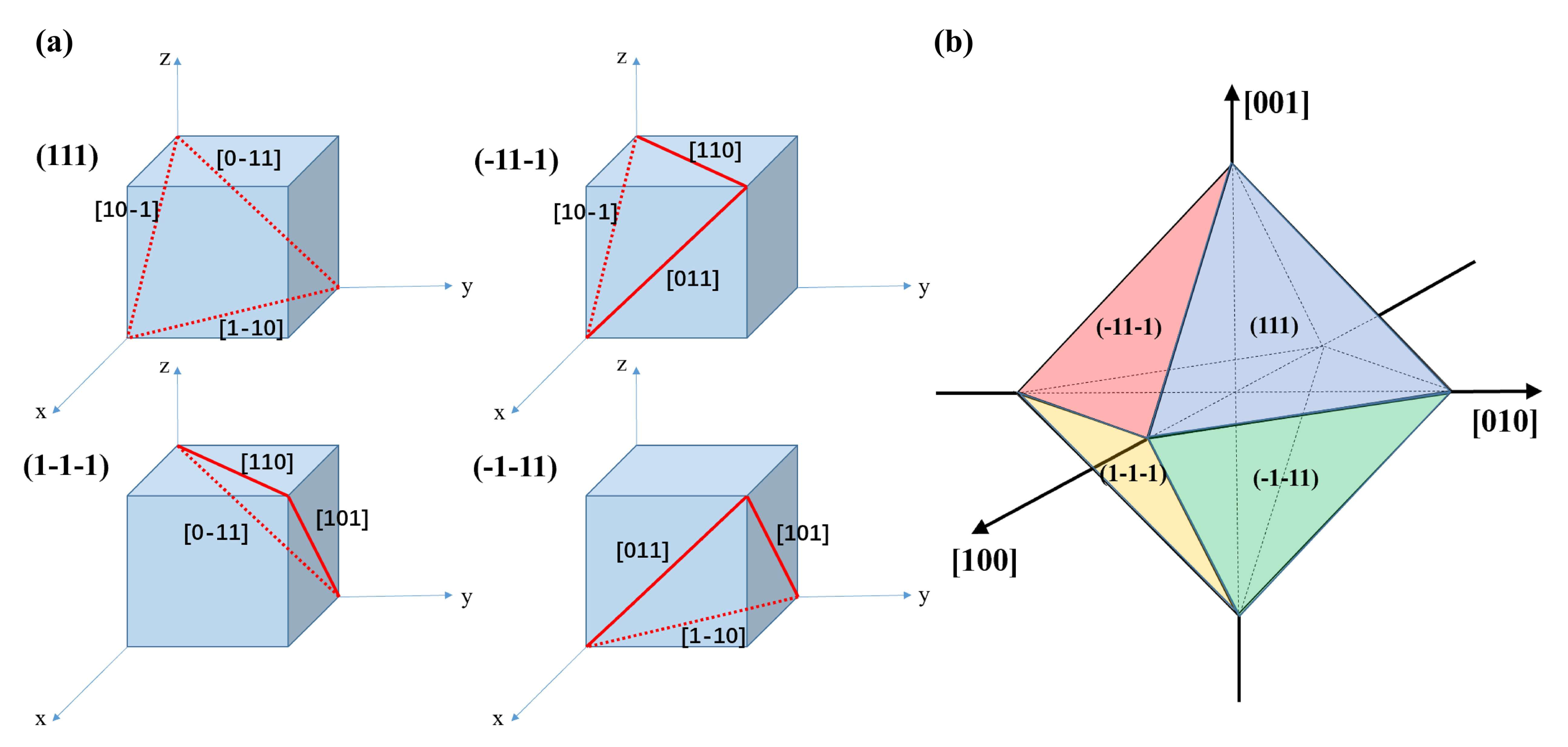
2. Models and Methods

NSCS is a kind of material usually composed of two basic phases, namely the matrix (γ) and strengthening (γ′) phases. The main component of the γ phase is Ni, which is a Face-Centered Cubic (FCC) structure, and the lattice constant is 0.352 nm; the γ′ phase is a stable and ordered intermetallic compound (Ni3Al) precipitated from the γ matrix [32,33,34,35], which also has an FCC structure with a similar lattice constant of 0.3567 nm. It is well known that NSCS has only one grain with the cubic γ′ phase uniformly coherent in the γ matrix. Three kinds of MD structure models have been proposed to describe the construction of NSCS to date: (I) a double-layer structure with an upper layer of Ni and a lower layer of Ni3Al [30]; (II) a sandwich structure with two (upper- and lower-) layers of Ni and a middle layer of Ni3Al [31]; (III) a unit structure [36] with a particle (γ’ supercell) embedded in the center of the γ matrix. It is obvious that the methods of I and II are too simple to present the real structure of NSCS. Method III using the representative unit could mimic the embedding scenery between the γ’ and γ, however, the basic unit cell model could not consider the relation between the particle and particle. With the above point of view in mind, a novel mosaic structure model was developed in this paper to imitate the structure of NSCS, which consists of 90 basic units, with each unit made up of a γ’ (6 × 6 × 6 lattices) embedded in γ (7 × 7 × 7 lattices) supercells. As shown in Figure 1a, a basic unit contains 1698 atoms with a 65% volume fraction of γ’ phase embedded in γ phase, in line with the actual situation of NSCS. Then the stacking of 90 units followed a size ratio which was similar to the working area of a real tensile sample. The different secondary orientations of 0°, 5°, 11°, 18°, 26°, 34°, 45°, 56°, 63°, 72°, 79°, 85° and 90° were obtained by rotating the above angles in (001) plane as presented in Figure 1b. The blue line showed a final contour of the MD model.
MD simulations were carried out with the Large-scale Atomic/Molecular Massively Parallel Simulator (LAMMPS) software (Version 21 Jul 2020) using an EAM potential function which concludes the coefficient of correction. In X and Y direction, the boundary conditions were periodic while in Z direction they were non-periodic (namely tensile direction), as shown in Figure 1c. Input parameters of material and simulation calculation are shown in Table 1. Before the external loading, the system needs relaxation till the energy of models fluctuates slightly. The temperature was maintained at 300 K and then increased to 1030 K; the tensile process was loaded by an elevated strain. The uniaxial stretching process was carried out in NPT (constant-pressure, constant-temperature) ensemble. The data processing of microstructure and dislocation was completed by the Ovito software (Version 2.9.0).

3. Results and Discussion

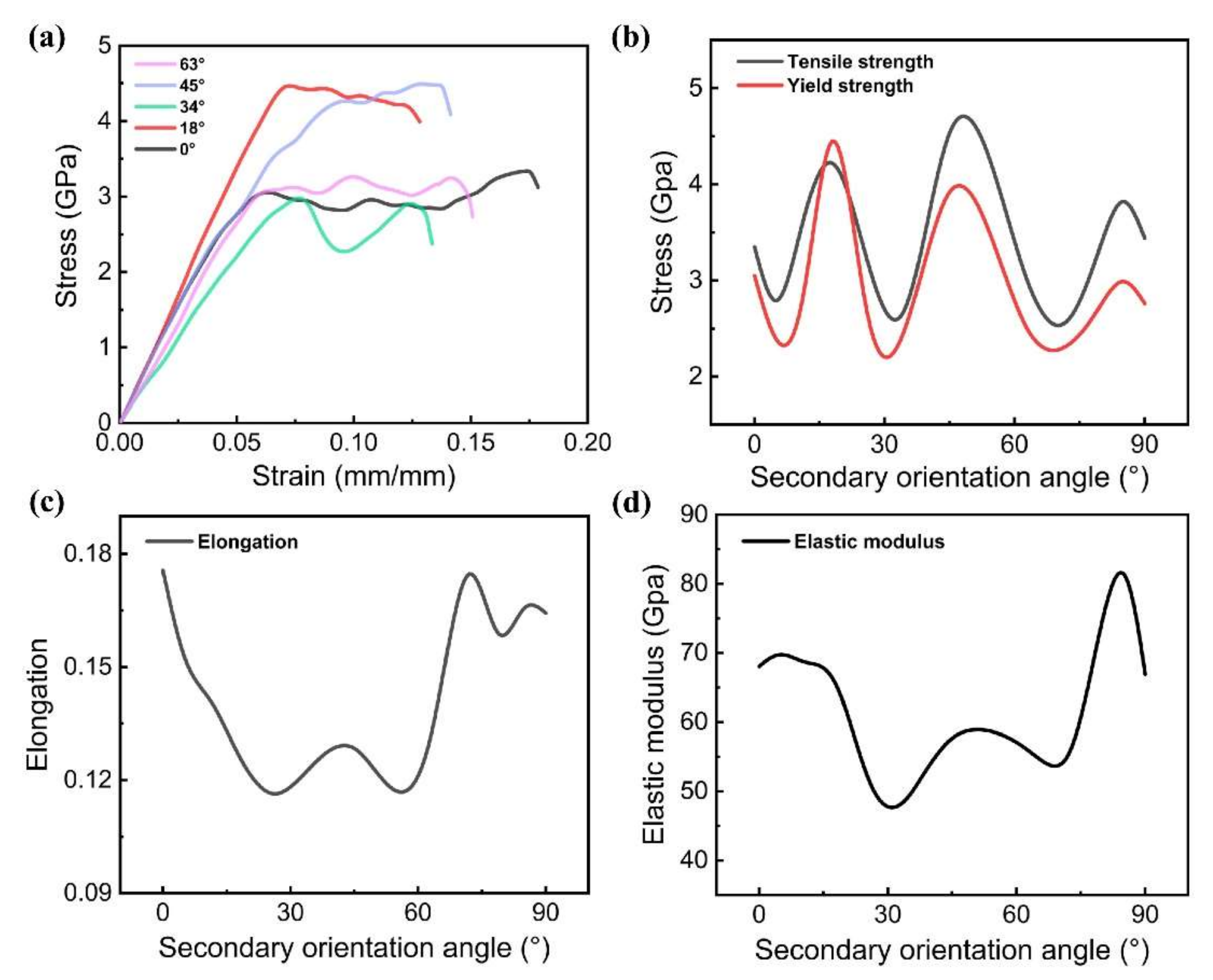
3.1. Effect of Secondary Orientation on Tensile Mechanical Properties

Figure 2 displays the results of tensile mechanical properties. Specifically, Figure 2a shows stress-strain curves of NSCS with different secondary orientations. Approximately, both have a bilinear characteristic before and after yielding, and it is found that secondary orientation has a significant influence on the deformation behavior of NSCS not only in the elastic stage, but also the plastic stage. In the simulation, the yield strength is defined as the strength at the end of elastic deformation, while the tensile strength is defined as the strength at break. As shown in Figure 2b, both the yield and tensile strengths [37] have a similar trend of change with secondary orientation, that is, both of them fluctuate up and down in the range of 0°~90°, reaching a peak at secondary orientations of 18°, 45°, 85° but a trough of wave at 5°, 34° and 63°. The value of the peak is as 1.5~2 times big as that of the trough on average. Moreover, when the secondary orientation is 90°, both the yield and tensile strengths are close to those of 0° due to the symmetrical characteristic of the model. Similarly, the fluctuation characteristic around these secondary orientation angles above are also found in the elongation and elastic modulus, as shown in Figure 2c,d. A possible explanation comes from the influence of secondary orientation on the activation of slip systems including the octahedral, hexahedral and dodecahedral slip systems. Therefore, these typical secondary orientation angles of 0°, 18°, 34°, 45° and 63° are selected in the subsequent microstructure studies.

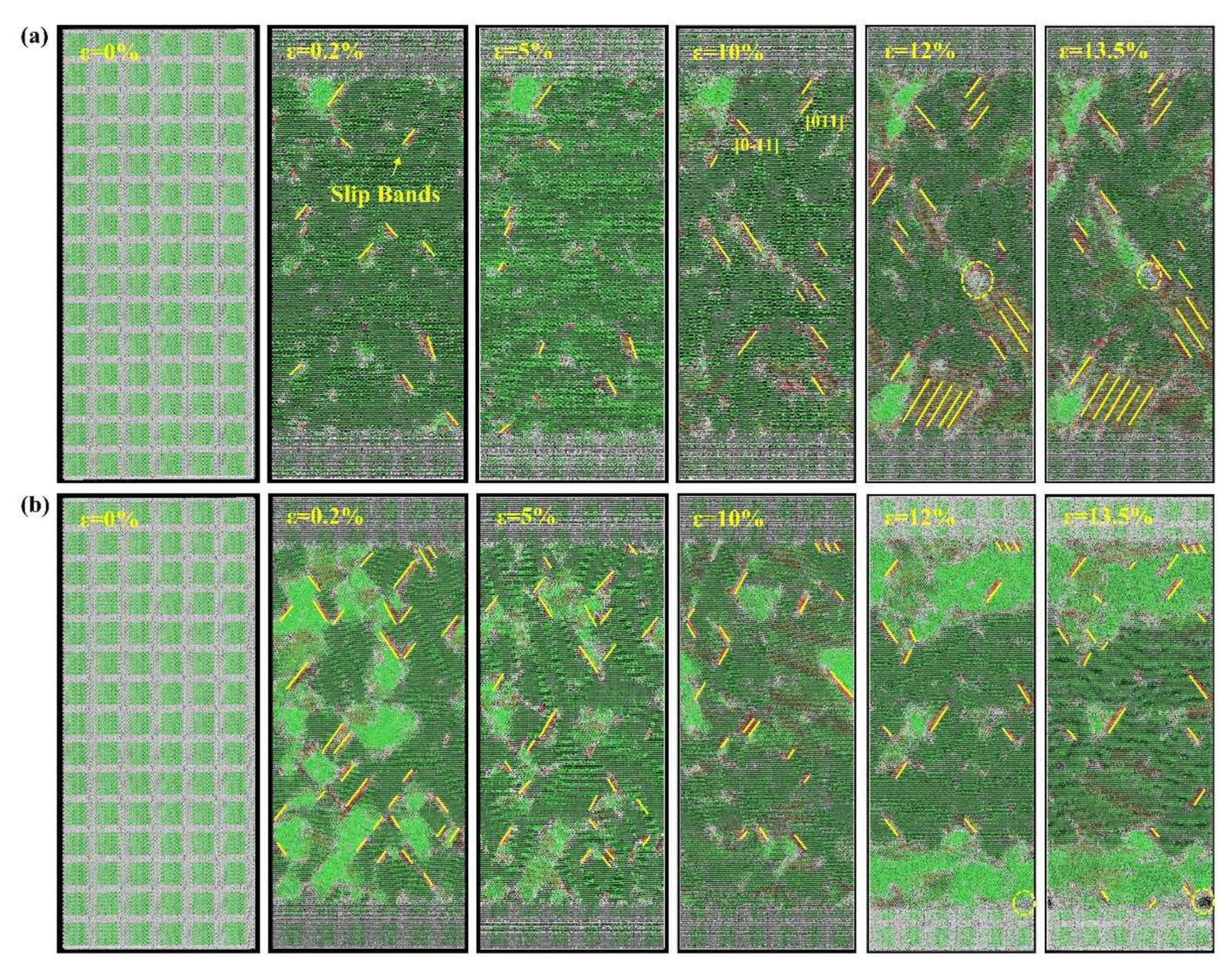
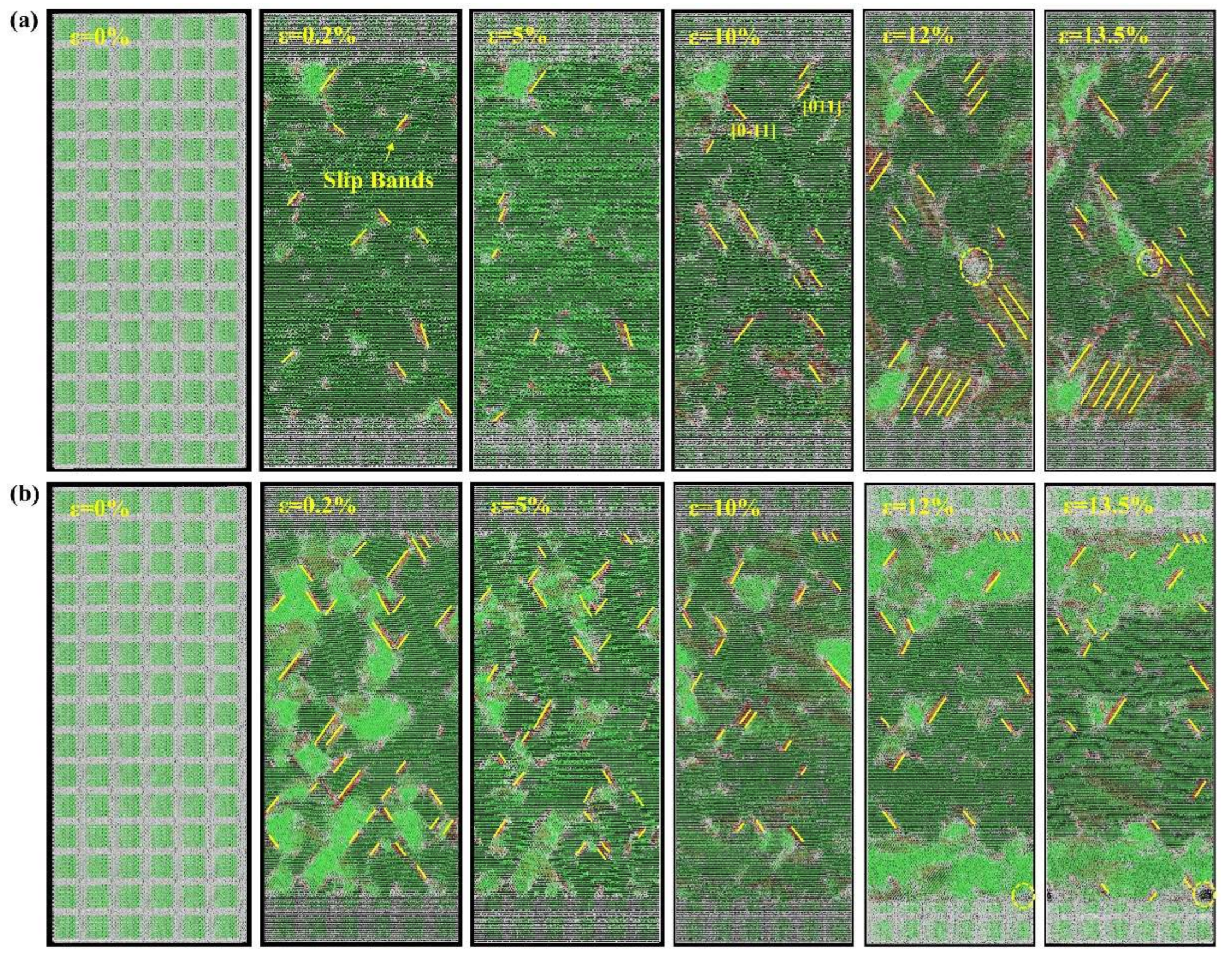
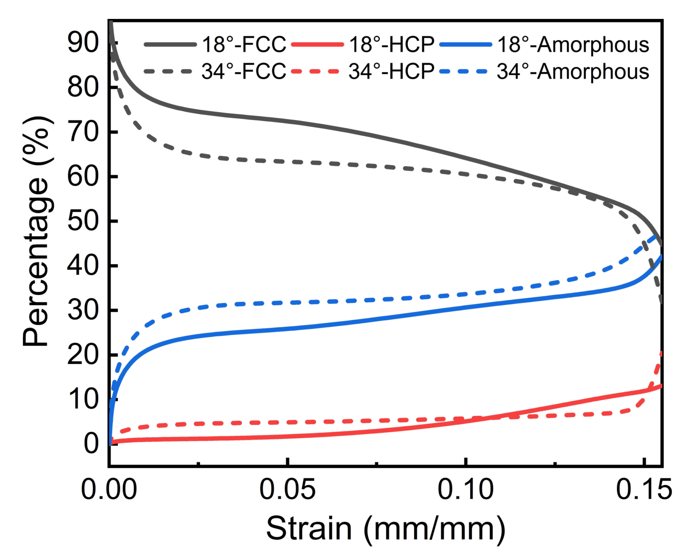
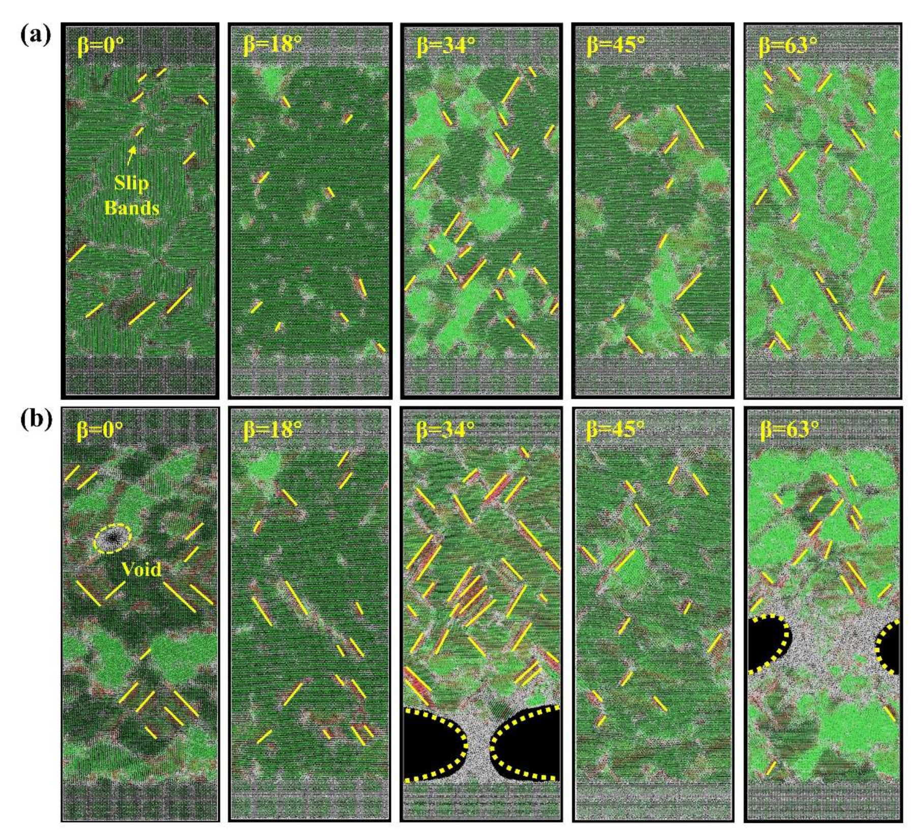
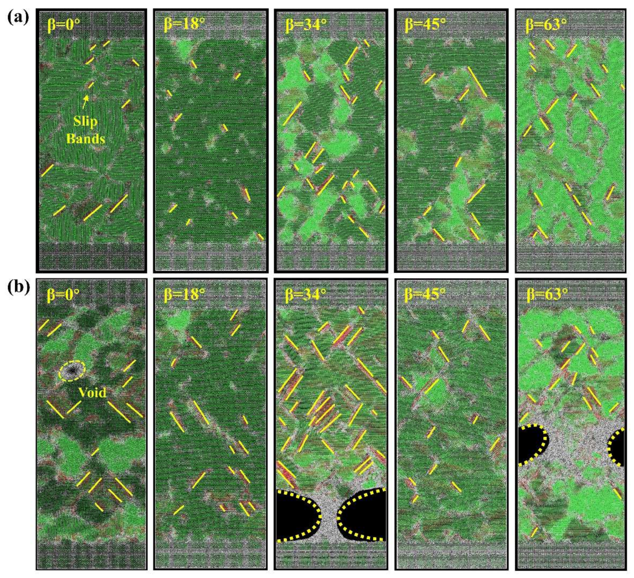
3.2. Evolution of Microstructure during Stretching

Figure 3 reveals the microstructure evolution of NSCS, in which the FCC, Hexagonal Close-Packed (HCP) and amorphous structure is green, red, and white, respectively. The damage of metal materials originally comes from the activation of the slip system. It can be seen that when ε = 0.2%, the ordered FCC structure begins to transform into a small part of HCP or amorphous structure together with the appearance of some slip bands; when ε = 5%, there is no significant change in microstructure; when ε = 10%, the change of deformation starts to accelerate; when ε = 12%, the material undergoes massive deformation and slip bands increases rapidly. The proportion of amorphous crystals in and around the yellow circle increased significantly, which is regarded as a precursor to large-scale amorphization [38]. At this time, the material structure is greatly changed by [011] and [ 0 1 - 1 ] slip directions in the octahedral slip system [39], while in the slip zone, it is composed of mixed HCP and amorphous structure; when ε = 13.5%, some initial microvoids start to form and it can be observed slightly. Then, voids will spread around and expand rapidly, resulting in the final fracture of the material.
In Figure 4, during the tensile process, the orderly FCC structure was transformed to HCP and amorphous structures. Firstly, with the increase of strain, the content of the main FCC structure decreases gradually while those of the HCP and amorphous structures increase steadily. When the strain is more than 10%, the change tendency of each phase content is accelerated. When the material has just passed the critical damage point (ε ≈ 13–14%), the proportion of the HCP and amorphous structures rise sharply. In addition, under an in-situ observation [40], the formation of a large number of voids has been found, which causes the damage and failure of materials; it was also similar to the MD simulations.
Figure 5 presents comparisons of microstructural evolutions among different secondary orientations of 0°, 18°, 34°, 45° and 63°. It is obviously found that when the stress reaches 1 GPa, these models with the secondary orientations of 34° and 63° have more HCP and amorphous phases, together with quite a few slip bands produced, which have a negative impact on the tensile strength of the material. In contrast, fewer slip bands are corresponding to those with the secondary orientations of 0°, 18°, and 45°. When the stress reaches 3.3 GPa, the secondary orientation of 0° is about to be damaged and fractured; however, the models with the secondary orientations of 34° and 63° have already shown huge voids, inducing damage due to the octahedral slip system, as reported [38]. In other words, the models with secondary orientations of 34° and 63° activate the slip system easier, leading to premature failure and a decrease in tensile strength, as plotted in Figure 2.

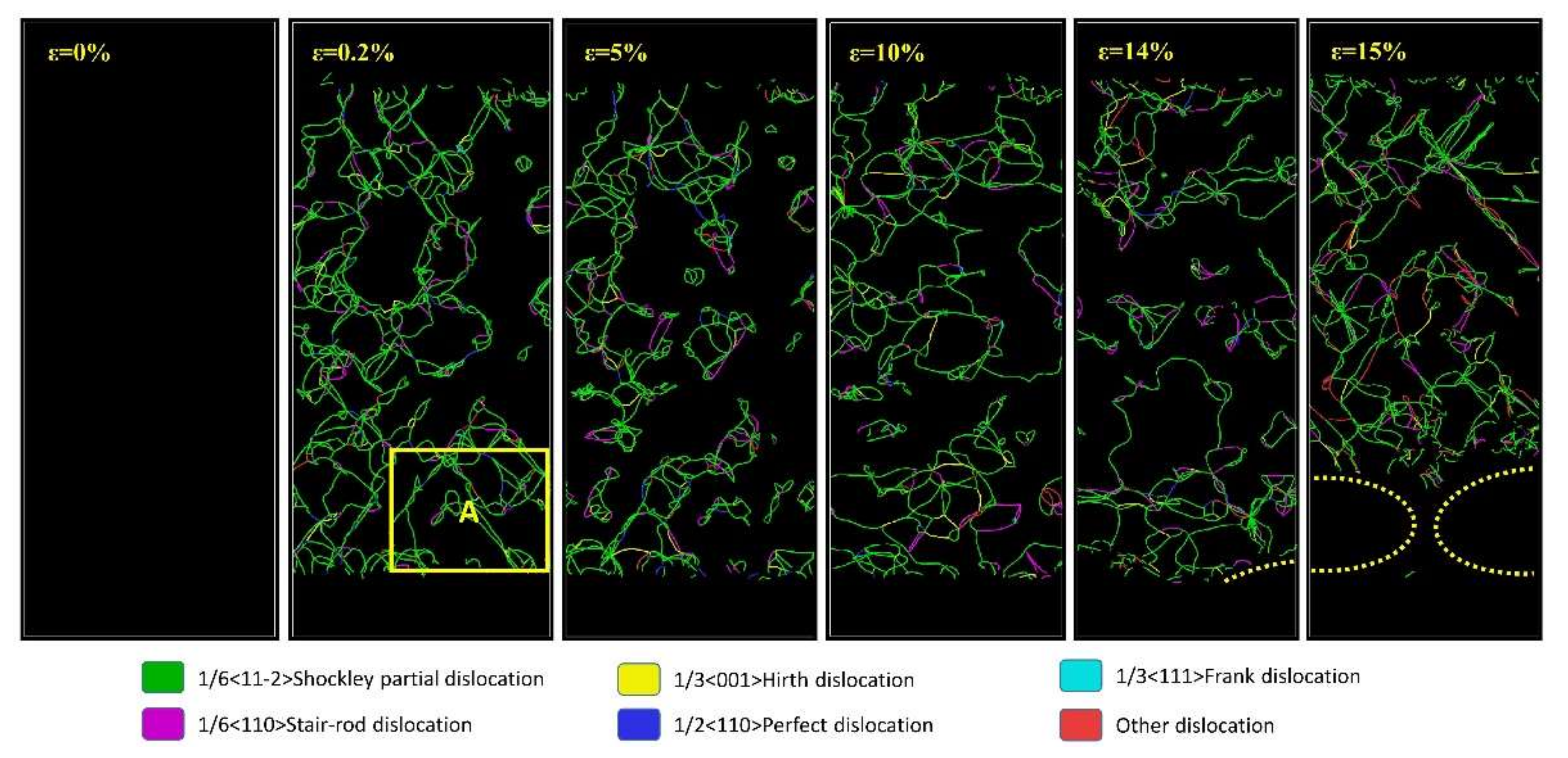
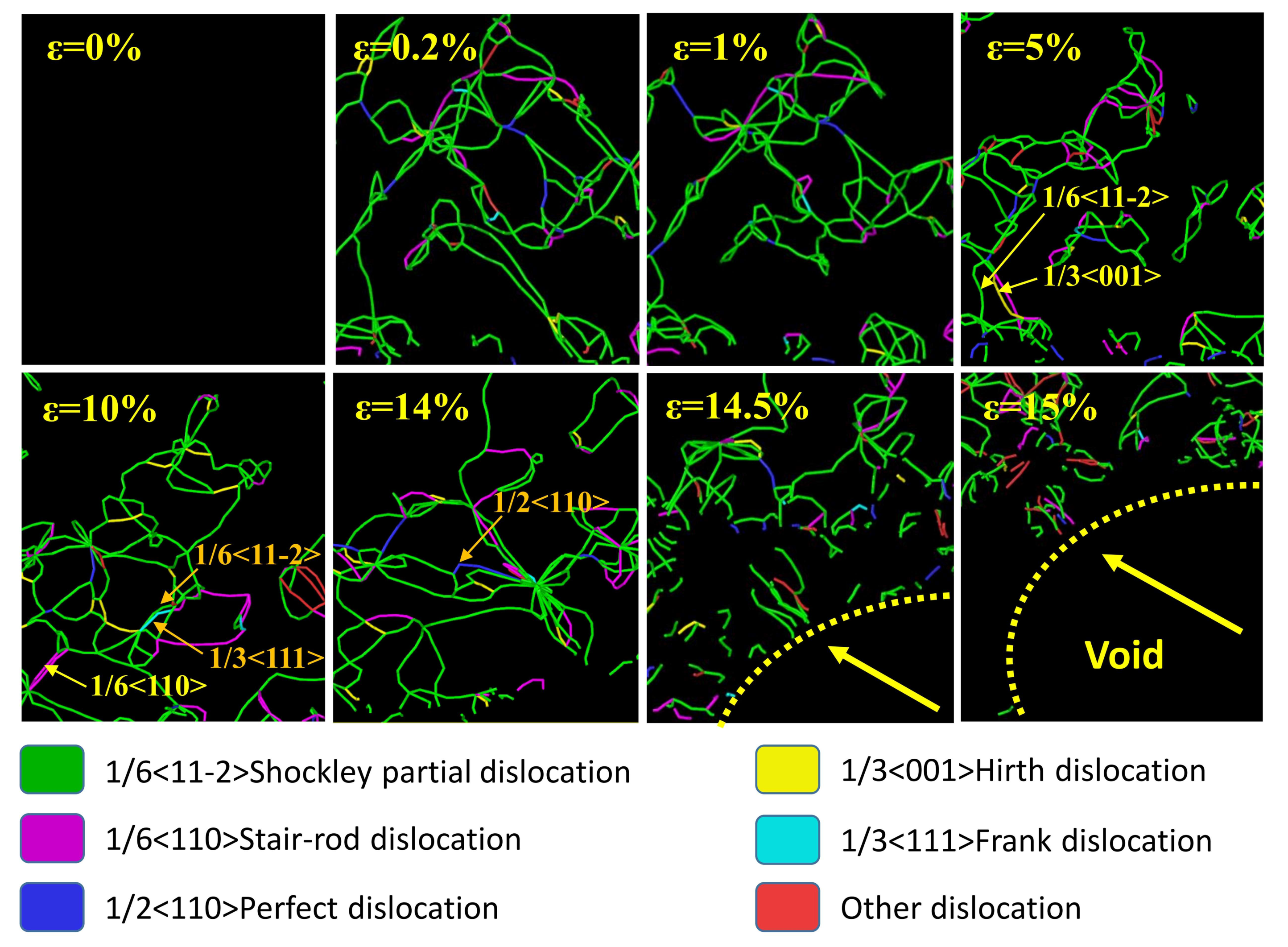
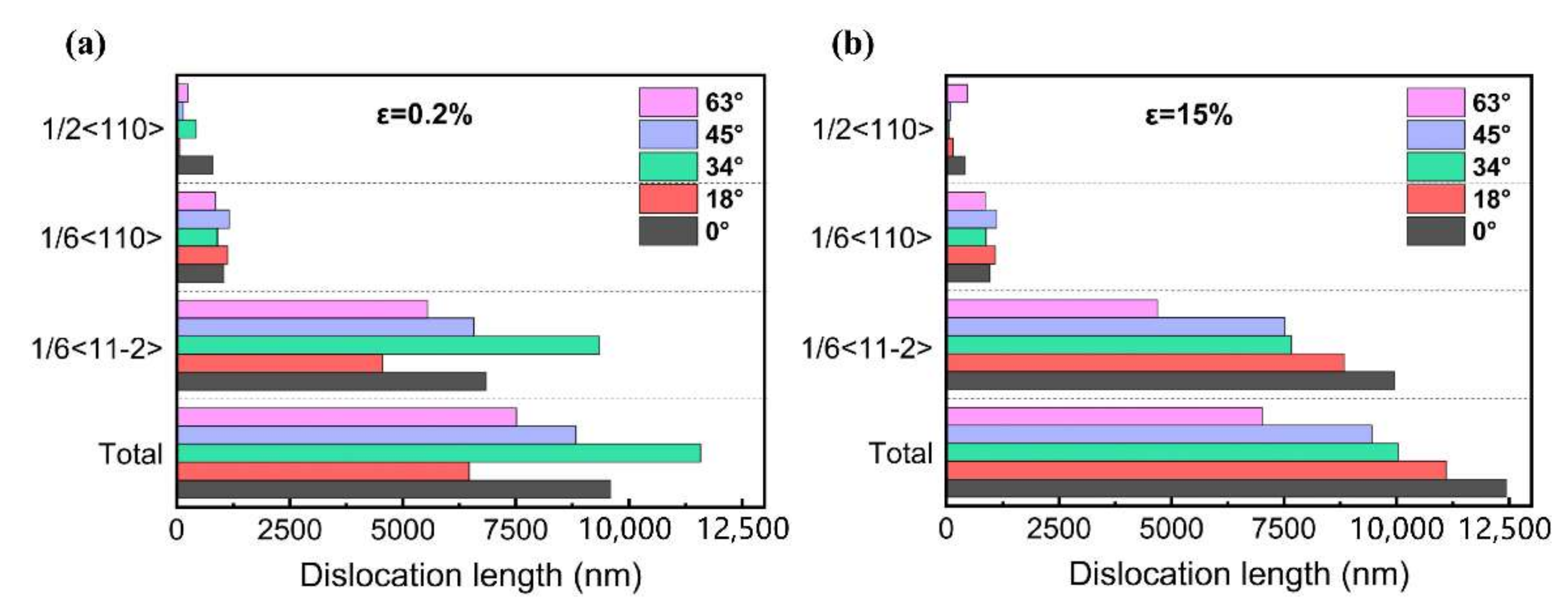
3.3. Evolution of Dislocations during Stretching

The evolution of dislocations in NSCS under a typical secondary orientation of 34° is presented in Figure 6. The result shows that dislocations produced in the tensile process are mainly Shockley partial dislocations (marked by green lines) as well as a few stair-rod dislocations (purple lines), perfect dislocations (blue lines) and other dislocations. Combined with Figure 4 and Figure 6, when deformation begins, the Shockley partial dislocations are emitted from the slip bands, which usually originate from a common dislocation source (namely dislocation junctions). With the strain increasing, more Shockley partial dislocations will be generated and a small number of perfect dislocations, stair-rod dislocations, Hirth dislocations and Frank dislocations are also generated. A large number of entangled dislocations are prone to occur in the slip bands and the region around the voids, which is especially obvious when ε = 5%. The squeezing of the atomic layer near these dislocations may lead to the activation of the octahedral slip system, an important reason for crack propagation and void expansion.
Figure 7 shows the evolution of dislocations in the region around location A in Figure 6. It can be seen that at the initial stage of tension, for example, ε = 0.2%, dislocations begin to germinate and most of them are the Shockley partial dislocations. When ε = 1%, some dislocations begin to gather together and a few new dislocations appear. When ε = 5%, the dislocation line density increases, and the distribution of dislocations changes remarkably, with some island-shaped dislocation cells produced as compared to the case of ε = 0.2%. Then with the increase of strain to ε = 10~14%, the density of dislocation lines reversely decreases, but the average length of dislocation lines increases. That is because some dislocations merge and expand. The merging mechanism between two different dislocations is found as follows: (i) Shockley + Hirth = Stair-rod: 1/6<11-2> + 1/3<001> = 1/6<110> (the yellow arrows); (ii) Shockley + Frank = Perfect: 1/6<11-2> + 1/3<111> = 1/2<110> (the orange arrows). Also, it is noted that some dislocation junctions are observed at the strain of 14%, and with the strain increased over 14.5%, these junctions break, leading to the fast fracture of materials with some big voids observed, as shown in Figure 5.
To compare the discrepancy of dislocation formation under different secondary orientations, the dislocation line lengths of the Shockley partial dislocations (1/6<11-2>), stair-rod dislocations (1/6<110>) and perfect dislocations (1/2<110>) are counted respectively, and the results are plotted in Figure 8. When the strain is 0.2%, the models with the secondary orientations of 34° and 63° have fewer stair-rod dislocations than those of 0°, 18° and 45°. Since the stair-rod dislocation generally causes the material hardening [41] (Figure 8a), low tensile properties are therefore obtained for the structures with the secondary orientations of 34° and 63°. But when the strain reaches 15%, the number of the Shockley partial dislocations is decreased with the occurrence of cracks caused by the generation of voids in the secondary orientations of 34° and 63°, as shown in Figure 8b. Due to fewer voids produced, the number of the Shockley partial dislocations still increases in the cases of the 18° and 45° secondary orientation models, relative to high tensile properties. Hence, fewer stair-rod dislocations make the octahedral slip system easier to activate; what’s more, the reduction of Shockley partial dislocations is mainly attributed to the formation of voids and dislocations merging, resulting in the reduction of material plasticity and causing the earlier fracture.
In addition, to reduce the consumption of time and computing power, it is worth mentioning that the width of γ’ precipitate phase in this model is much smaller than the actual size. However, for the cubic structure model, the volume fraction of γ‘ phase in this model is 65.3%, which ensures that the ratio of γ’ phase to γ phase size is consistent with the actual material. In this study, the simulation of the exposed surface with different secondary orientations can find that there is dislocation network embedded in the γ’ precipitate phase, which is closely resembled with the experimental observations [42,43], so the change of model size did not change the morphology of dislocation [44,45]. Besides, because of the small time scale of MD simulation, the strain rate was also much faster than the experimental test situation [46,47,48]. Instead of the quantitative research of absolute value, many studies have conducted qualitative research on the deformation mechanism and mechanical behavior of materials from the atomic scale. Therefore, when the size ratio of the γ’ phase to γ phase is fixed, the MD model can describe the basic physical phenomena such as the morphology of dislocation structure and the characteristics of dislocation evolution. All of the above indicate the MD simulation results obtained in this work can reasonably reflect the damage behavior and deformation mechanism of NSCS during the tensile process on the atomic scale.

3.4. Comprehensive Mechanisms of Deformation and Fracture

As discussed above, the tensile strength, elongation and elastic modulus of NSCS are significantly affected by secondary orientations, especially at the secondary orientations of 34° and 63° with a relatively lower tensile strength, which is related to the easier activation of the slip system caused by the lower number of stair-rod dislocations. Generally, there are three kinds of slip systems in NSCS, namely the octahedral, hexahedral and dodecahedral slip systems [49,50,51,52]. As reported in Ref. [52], the most easily activated slip system is the octahedral slip system, where the angle of slip direction in each slip plane is 60° (Figure 9a) and the four slip planes constitute the octahedral slip system (Figure 9b). So, it is easier to fracture at about 30° or 60°, agreeing well with the predictions of the secondary orientations of 34° or 64° in this paper. In addition, dislocation characteristics including density, shape and distribution, etc. also affect the mechanical property and deformation mechanism. According to the previous report [41], the lower percentage of stair-rod dislocations (ε = 0.2%) generated in the models with the secondary orientations of 34° and 63°, cause the easy activation of the octahedral slip system, leading to low tensile properties. In contrast, high tensile properties in the cases with the secondary orientations of 0°, 18° and 45° are caused not only by the considerable stair-rod dislocations, but also the Shockley partial dislocation, which can improve the plasticity of a material. In sum, the superposition of some complex factors above results in a big fluctuation in mechanical properties with the varied secondary orientation.

4. Conclusions

A mosaic structure MD model was developed to study the effect of secondary orientation on mechanical properties and microstructure evolution of NSCS under uniaxial tensile. The effect of secondary orientation on the mechanical behavior of NSCS showed a fluctuation mode for such properties like yield strength, tensile strength, elongation, etc. in the range of 0~90°. The cases with the secondary orientations of 34° and 63° were more prone to deformation due to the activation of the octahedral slip system. In contrast, those cases with the secondary orientations of 18° and 45° were not easy to deform or damage, getting better mechanical properties. During the tensile process, the ordered FCC structure in NSCS was found to transform into the HCP structure or disordered amorphous structure, and the deformation characteristic of NSCS was tending towards amorphization of microstructure, together with the formation, merging and break-up of some dislocations. The main dislocation merging of “Shockley + Hirth = Stair-rod” and “Shockley + Frank = Perfect” were also observed. The present study enriches the understanding of the effect of secondary orientation on the deformation behavior of NSCS at atomic scale.

Author Contributions

Methodology, Formal analysis, Writing—original draft, W.W.; Writing—review & editing, J.Z. and F.L.; Project administration, F.L.; Investigation, S.N.; Resources, L.L.; Data acquisition, Funding acquisition, J.S. and C.X. All authors have read and agreed to the published version of the manuscript.

Funding

This research was funded by the Foundation of Science and Technology on Advanced High Temperature Structural Materials Laboratory, AECC Beijing Institute of Aeronautical Materials, China (Grant No. 6142903200105).

Institutional Review Board Statement

Not applicable.

Informed Consent Statement

Not applicable.

Data Availability Statement

Not applicable.

Acknowledgments

The authors would like to thank the Foundation of Science and Technology on Advanced High Temperature Structural Materials Laboratory, AECC Beijing Institute of Aeronautical Materials, China (Grant No. 6142903200105) for technology and financial support.

Conflicts of Interest

The authors declare no conflict of interest.

References

  1. Li, J.R.; Jin, H.P.; Liu, S. Stress rupture properties and microstructures of the second generation single crystal superalloy DD6 after long term aging at 98 °C. Rare Met. Mater. Eng. 2007, 36, 1784–1787. [Google Scholar]
  2. Roebuck, B.; Cox, D.; Reed, R. The temperature dependence of γ′ volume fraction in a Ni-based single crystal superalloy from resistivity measurements. Scr. Mater. 2001, 44, 917–921. [Google Scholar] [CrossRef]
  3. Pollock, T.M.; Tin, S. Nickel-based superalloys for advanced turbine engines: Chemistry, microstructure, and properties. J. Propul. Power 2006, 22, 361–374. [Google Scholar] [CrossRef]
  4. Xia, W.; Zhao, X.; Yue, L.; Zhang, Z. A review of composition evolution in Ni-based single crystal superalloys. J. Mater. Sci. Technol. 2020, 44, 76–95. [Google Scholar] [CrossRef]
  5. Long, H.; Mao, S.; Liu, Y.; Zhang, Z.; Han, X. Microstructural and compositional design of Ni-based single crystalline superalloys—A review. J. Alloys Compd. 2018, 743, 203–220. [Google Scholar] [CrossRef]
  6. Wen, Z.X.; Liang, J.W.; Liu, C.Y.; Pei, H.Q.; Wen, S.F.; Yue, Z.F. Prediction method for creep life of thin-wall specimen with film cooling holes in Ni-based single-crystal superalloy. Int. J. Mech. Sci. 2018, 141, 276–289. [Google Scholar] [CrossRef]
  7. Kim, Y.J.; Kim, S.M. Influence of shaped injection holes on turbine blade leading edge film cooling. Int. J. Heat Mass Transf. 2004, 47, 245–256. [Google Scholar] [CrossRef]
  8. Zhao, X.B.; Liu, L.; Yu, Z.H. Microstructure development of different orientated nickel-base single crystal superalloy in directional solidification. Mater. Charact. 2009, 61, 7–12. [Google Scholar] [CrossRef]
  9. MacKay, R.A.; Maier, R.D. The influence of orientation on the stress rupture properties of nickel-base super-alloy single-crystals. Metall. Trans. A 1982, 13, 1747–1754. [Google Scholar] [CrossRef]
  10. Sass, V.; Glatzel, U.; FellerKniepmeier, M. Anisotropic creep properties of the nicker-base superalloy CMSX-4. Acta Mater. 1996, 44, 1967–1977. [Google Scholar] [CrossRef]
  11. Lukas, P.; Cadek, J.; Sustek, V.; Kunz, L. Creep of CMSK-4 single crystals of different orientations in tension and compression. Mater. Sci. Eng. A 1996, 208, 149–157. [Google Scholar] [CrossRef]
  12. Nunez, J.E.; Glinka, G. Analysis of non-localized creep induced strains and stresses in notches. Eng. Fract. Mech. 2004, 71, 1791–1803. [Google Scholar] [CrossRef]
  13. Mao, H.Z.; Wen, Z.X.; Yue, Z.F.; Wang, B.Z. The evolution of plasticity for nickel-base single crystal cooled blade with film cooling holes. Mater. Sci. Eng. A 2013, 587, 79–84. [Google Scholar] [CrossRef]
  14. Yu, Q.M.; Yue, Z.F.; Wen, Z.X. Creep damage evolution in a modeling specimen of nickel-based single crystal superalloys air-cooled blades. Mater. Sci. Eng. A 2008, 477, 319–327. [Google Scholar] [CrossRef]
  15. Zienkiewicz, O.C.; Pastor, M.; Huang, M. Softening, localisation and adaptive remeshing. Capture of discontinuous solutions. Comp. Mech. 1995, 17, 98–106. [Google Scholar] [CrossRef]
  16. Hou, N.X.; Gou, W.X.; Wen, Z.X.; Yue, Z.F. The influence of crystal orientations on fatigue life of single crystal cooled turbine blade. Mater. Sci. Eng. A 2008, 492, 413–418. [Google Scholar] [CrossRef]
  17. Arakere, N.K.; Swanson, G.R. Effect of crystal orientation on fatigue failure of single crystal nickel base turbine blade superalloys. ASME J. Gas Turbines Power 2002, 124, 161–176. [Google Scholar] [CrossRef] [Green Version]
  18. Getsov, L.; Dobina, N.; Rybnikov, A. Thermal fatigue of a Ni-based superalloy single crystal. Mater. Technol. 2007, 41, 67–72. [Google Scholar]
  19. Wang, L.; Zhou, Z.; Jiang, W. Effect of secondary orientation on thermal fatigue behavior of a nickel-base single crystal superalloy DD33. Chin. J. Mater. Res. 2014, 28, 663–667. [Google Scholar]
  20. Yang, W.P.; Li, J.R.; Liu, S.Z. Orientation dependence of transverse tensile properties of nickel based third generation single crystal superalloy DD9 from 760 to 1100 °C. Trans. Nonferrous Met. Soc. Chin. 2019, 29, 558–568. [Google Scholar] [CrossRef]
  21. Zhai, Y.; Khan, M.K.; Correia, J.; de Jesus, A.M.; Huang, Z.; Zhang, X.; Wang, Q. Effect of secondary crystal orientations on the deformation anisotropy for nickel-based single-crystal plate with notch feature. J. Strain Anal. 2019, 54, 54–64. [Google Scholar] [CrossRef]
  22. Ren, J.Q.; Sun, Q.Y.; Xiao, L. Temperature and strain rate effect of the deformation-induced phase transformation in pure titanium nanopillars oriented along [0001]. Comp. Mater. Sci. 2017, 126, 66–73. [Google Scholar] [CrossRef]
  23. Tang, T.; Kim, S.; Jordon, J.B.; Horstemeyer, M.F.; Wang, P.T. Atomistic simulations of fatigue crack growth and the associated fatigue crack tip stress evolution in magnesium single crystals. Comp. Mater. Sci. 2011, 50, 2977–2986. [Google Scholar] [CrossRef]
  24. Sainath, G.; Choudhary, B.K.; Jayakumar, T. Molecular dynamics simulation studies on the size dependent tensile deformation and fracture behaviour of body centred cubic iron nanowires. Comp. Mater. Sci. 2015, 104, 76–83. [Google Scholar] [CrossRef]
  25. Lubarda, V.A.; Schneider, M.S.; Kalantar, D.H.; Remington, B.A.; Meyers, M.A. Void growth by dislocation emission. Acta Mater. 2004, 52, 1397–1408. [Google Scholar] [CrossRef]
  26. Zhu, Y.X.; Li, Z.H.; Huang, M.S. Atomistic modeling of the interaction between matrix dislocation and interfacial misfit dislocation networks in Ni-based single crystal superalloy. Comp. Mater. Sci. 2013, 70, 178–186. [Google Scholar] [CrossRef]
  27. Xiong, J.; Zhu, Y.X.; Li, Z.H.; Huang, M.S. Quantitative study on interactions between interfacial misfit dislocation networks and matrix dislocations in Ni-based single crystal superalloys. Acta Mech. Solida Sin. 2017, 30, 345–353. [Google Scholar] [CrossRef]
  28. Shang, J.; Yang, F.; Li, C.; Wei, N.; Tan, X. Size effect on the plastic deformation of pre-void Ni/Ni3Al interface under uniaxial tension: A molecular dynamics simulation. Comp. Mater. Sci. 2018, 148, 200–206. [Google Scholar] [CrossRef]
  29. Chen, B.; Wu, W.P.; Chen, M.X.; Guo, Y.F. Molecular dynamics study of fatigue mechanical properties and microstructural evolution of Ni-based single crystal superalloys under cyclic loading. Comp. Mater. Sci. 2020, 185, 109954. [Google Scholar] [CrossRef]
  30. Xie, H.X.; Wang, C.Y.; Yu, T. Dislocation formation and twinning from the crack tip in Ni3Al: Molecular dynamics simulations. Chin. Phys. B 2009, 18, 251–258. [Google Scholar]
  31. Wu, W.P.; Guo, Y.F.; Wang, Y.S. Molecular dynamics simulation of the structural evolution of misfit dislocation networks at γ/γ′ phase interfaces in Ni-based superalloys. Philos. Mag. 2011, 91, 357–372. [Google Scholar] [CrossRef]
  32. Chen, J.Y.; Zhao, B.; Feng, Q. Effects of Ru and Cr on γ/γ' microstructural evolution of Ni-based single crystal superalloys during heat treatment. Acta Metall. Sin. 2010, 46, 897–906. [Google Scholar] [CrossRef]
  33. Nganbe, M.; Heilmaier, M. Modelling of particle strengthening in the γ' and oxide dispersion strengthened nickel-base superalloy PM3030. Mater. Sci. Eng. A 2004, 387, 609–612. [Google Scholar] [CrossRef]
  34. Wang, K.G.; Li, J.R.; Liu, S.Z. Study on creep properties of single crystal superalloy DD6 at 760 °C. J. Mater. Eng. 2004, 5, 7–11. [Google Scholar] [CrossRef]
  35. Murakumo, T.; Kobayashi, T.; Koizumi, Y. Creep behaviour of Ni base single crystal superalloys with various γ’ volume fraction. Acta Mater. 2004, 52, 3737–3744. [Google Scholar] [CrossRef]
  36. Zhu, T.; Wang, C.Y.; Gan, Y. Evolution of misfit dislocation network at phase interface of nickel base single crystal superalloy. Acta Phys. Sin. 2009, 58, 156–160. [Google Scholar]
  37. Wei, W.C.; Zhang, J.W.; Song, J.X.; Xiao, C.B.; Liu, F.R. Effect of secondary orientation on micromechanical properties of nickel base single crystal superalloy. J. Phys. Conf. Ser. 2021, 1907, 012011. [Google Scholar] [CrossRef]
  38. Lin, Y.H.; Chen, T.C. Nanoscale Mechanical and Mechanically-Induced Electrical Properties of Silicon Nanowires. Crystals 2019, 9, 240. [Google Scholar] [CrossRef] [Green Version]
  39. Lian, Z.W.; Yu, J.J.; Sun, X.F.; Guan, H.R.; Hu, Z.Q. Temperature dependence of tensile behavior of Ni-based superalloy M951. Mater. Sci. Eng. A 2008, 489, 227–233. [Google Scholar] [CrossRef]
  40. Koglin, J.; Coakley, J.; Higginbotham, A. Femtosecond quantification of void evolution during rapid material failure. Sci. Adv. 2020, 6, eabb4434. [Google Scholar]
  41. Feng, H.; Cui, S.Y.; Chen, H.T. A molecular dynamics investigation into deformation mechanism of nanotwinned Cu/high entropy alloy FeCoCrNi nanolaminates. Surf. Coat. Technol. 2020, 401, 126325. [Google Scholar] [CrossRef]
  42. Li, Y.; Li, P.; Li, J.R.; Wu, X.R. Static tensile properties of a kind of single crystal nickel-based superalloy at different temperatures. J. Aero. Power 2005, 6, 958–963. [Google Scholar]
  43. Zhang, J.; Guo, Y.Y.; Zhang, M.; Yang, Z.Y.; Luo, Y.S. Low-Cycle Fatigue and Creep-Fatigue Behaviors of a Second-Generation Nickel-Based Single-Crystal Superalloy at 760 °C. Acta Metall. Sin. 2020, 33, 1423–1432. [Google Scholar] [CrossRef]
  44. Zhu, T.; Wang, C.Y. Molecular dynamics study of mosaic structure in the Ni-based single-crystal superalloy. Chin. Phys. B 2006, 15, 2087–2091. [Google Scholar]
  45. Li, Y.L.; Wu, W.P.; Ruan, Z.G. Molecular dynamics simulation of the evolution of interfacial dislocation network and stress distribution of a Ni-based single-crystal superalloy. Acta Metall. Sin. 2016, 29, 689–696. [Google Scholar] [CrossRef] [Green Version]
  46. Li, H.; Du, W.; Liu, Y. Molecular dynamics study of tension process of Ni-Based superalloy. Acta Metall. Sin. 2020, 33, 741–750. [Google Scholar] [CrossRef]
  47. Houllé, F.; Walsh, F.; Prakash, A.; Bitzek, E. Atomistic simulations of compression tests on γ-Precipitate Containing Ni3Al Nanocubes. Metall. Mater. Trans. A 2018, 49, 4158–4166. [Google Scholar] [CrossRef]
  48. Liu, H.; Wang, X.M.; Liang, H.; Zhao, Z.N.; Li, L.; Yue, Z.F.; Deng, C.H. The effect of void defect on the evolution mechanisms of dislocations and mechanical properties in nickel-based superalloys by molecular dynamics simulation of real γ/γ’ structures. Int. J. Solids Struct. 2020, 191, 464–472. [Google Scholar] [CrossRef]
  49. Gunturi, S.S.K.; MacLachlan, D.W.; Knowles, D.M. Anisotropic creep in CMSX-4 in orientations distant from <001>. Mater. Sci. Eng. A 2000, 289, 289–298. [Google Scholar] [CrossRef]
  50. Zhang, J.X.; Murakumo, T.; Harada, H. Dependence of creep strength on the interfacial dislocations in a fourth generation SC superalloy TMS-138. Scr. Mater. 2003, 48, 287–293. [Google Scholar] [CrossRef]
  51. Caillard, D.; Martin, J.L. Glide of dislocations in non-octahedral planes of fcc metals: A review. Inter. J. Mater. Res. 2009, 100, 1403–1410. [Google Scholar] [CrossRef]
  52. Yue, Z.F.; Lu, Z.Z. The influence of crystallographic orientation and strain rate on the high-temperature low-cyclic fatigue property of a nickel-base single-crystal superalloy. Metall. Mater. Trans. A 1998, 29, 1093–1099. [Google Scholar] [CrossRef]
Figure 1. Model construction: (a) geometry of tensile samples and establishment of MD supercell model for NSCS; (b) creation method of different secondary orientations in the MD model; (c) loading of the supercell model.
Metals 12 00217 g001
Figure 2. Effects of different secondary orientations on tensile properties of NSCS. (a) stress-strain curves; (b) yield and tensile strength; (c) elongation curves; (d) elastic modulus curves.
Metals 12 00217 g002
Figure 3. Structural evolutions of NSCS with two typical secondary orientations of (a) 18° and (b) 34° during the tensile process. The green (dark and light), red and white are the FCC, HCP and amorphous regions, respectively. The yellow lines show the slip lines.
Metals 12 00217 g003
Figure 4. Content variations of the FCC, HCP and amorphous phases for two typical secondary orientations of 18° and 34° during the tensile process.
Metals 12 00217 g004
Figure 5. Comparison of structural evolutions among different secondary orientations when the stress reaches (a) 1 GPa and (b) 3.3 GPa. The dashed lines in (b) show the contour of voids.
Metals 12 00217 g005
Figure 6. Dislocation dynamic evolution in NSCS with a secondary orientation of 34° during the tensile process. The dashed lines show the contour of voids.
Metals 12 00217 g006
Figure 7. Tracing the dislocation evolution near the area of “A” marked in Figure 6.
Metals 12 00217 g007
Figure 8. Statistics of the dislocation line length at different secondary orientations under the strains of (a) 0.2% and (b) 15%.
Metals 12 00217 g008
Figure 9. Relationship of the slip plane and slip direction for the octahedral slip system. (a) Four different kinds of slip planes with the red lines showing the slip directions. (b) The octahedral slip system made up of four slip planes shown in (a).
Metals 12 00217 g009
Table 1. Input parameters of material and simulation calculation.
Material Lattice
Constant (Å)
Force Field ParametersOperating Parameters
NiNi3AlPotential functionEnsembleTime step (fs)Run steps
3.5243.567NiAlH_jea.eam.alloyNVT,NPT150,000
Publisher’s Note: MDPI stays neutral with regard to jurisdictional claims in published maps and institutional affiliations.

