Article

Effect of Vacancies on Dynamic Response and Spallation in Single-Crystal Magnesium by Molecular Dynamic Simulation

1
Department of Applied Physics, School of Physics and Electronics, Hunan University, Changsha 410082, China
2
College of Materials Science and Engineering, Hunan University, Changsha 410082, China
*
Author to whom correspondence should be addressed.
Metals 2022, 12(2), 215; https://doi.org/10.3390/met12020215
Submission received: 21 December 2021 / Revised: 11 January 2022 / Accepted: 21 January 2022 / Published: 24 January 2022
(This article belongs to the Special Issue Atomistic Simulations under Extreme Conditions)

Abstract

:
The effect of vacancies on dynamic response and spallation in single-crystal magnesium (Mg) is investigated by nonequilibrium molecular dynamics simulations. The initial vacancy concentration (Cv) ranges from 0% to 2.0%, and the shock loading is applied along [0001] and [10–10] directions. The simulation results show that the effects of vacancy defects are strongly dependent on the shock directions. For shock along the [0001] direction, vacancy defects have a negligible effect on compression-induced plasticity, but play a role in increasing spall damage. In contrast, for shock along the [10–10] orientation, vacancy defects not only provide the nucleation sites for compression-induced plasticity, which mainly involves crystallographic reorientation, phase transition, and stacking faults, but also significantly reduce spall damage. The degree of spall damage is probably determined by a competitive mechanism between energy absorption and stress attenuation induced by plastic deformation. Void evolution during spallation is mainly based on the emission mechanism of dislocations. The {11–22} <11–23> pyramidal dislocation facilitates the nucleation of void in the [0001] shock, as well as the {1–100} <11–20> prismatic dislocation in the [10–10] shock. We also investigated the variation of spall strength between perfect and defective Mg at different shock velocities. The relevant results can provide a reference for future investigations on spall damage.

1. Introduction

Spallation is an important subject in dynamic damage research, which can be observed in the local tensile stress region caused by the interaction of the unloading compression wave and rarefaction wave formed from the free surface of the target. Experimentally, the most widely used methods to investigate spall failure are plate impact experiments [1,2,3] or laser pulse [4,5,6]. For example, Wang et al. [3] compared the spall strength of four aluminum materials and discussed the damage mechanism by plate impact experiments. By using a laser shock, the spall strength and fragmentation of single-crystal magnesium at very high strain rates of about 107 s−1 were provided [6]. In experiments, the study of spall failure was to obtain effective information about spall strength (σsp) and dynamics by measuring and analyzing the velocity history of free surface of the samples [7]. However, it was difficult to describe and identify the individual contributions of various microscopic processes to the overall material reaction because of the very short time and length scale of the processes involved. Molecular dynamics (MD) simulations make it possible to study atomic level evolution of microstructure, and have been widely used to investigate the dynamic failure behavior in different materials [8,9,10,11,12,13,14]. For example, Luo et al. [10] studied spall damage of single-crystal Cu under square and Taylor shock wave loading using MD simulations. The results showed that the spall strength of Taylor wave loading was higher than that of square shock loading at the same shock velocities. Agarwal and Dongare [14] investigated the effects of loading direction, impact pressure, and initial temperature on spallation of single-crystal magnesium with MD simulations, and found that the spall strength decreased with the increase in impact strength and initial temperature. Gunkelmann et al. [11] performed MD simulations of shock-induced spallation in polycrystalline iron and found that spall damage was strongly affected by the phase transition, leading to the change of fracture surface morphology. Chen et al. [13] studied the effect of grain boundaries (GBs) on spall behavior in the metal Ta by MD simulations. They demonstrated the correlation between GB structure, GB plasticity mechanism, and the resulting spall strength. Wang et al. [8] found that release melting and shock melting occurred when the shock velocities increased in the metal tin via MD. The spall strength decreased rapidly when release melting occurred, while the downtrend of the spall strength became gentle during shock melting. In addition to the effects of pressure, temperature, and shock velocity, the influence of defect structures on the spallation of materials has also been given attention in the abovementioned studies. However, considering the wide variety of defects in actual metals and alloys, individual contributions are difficult to separate. Vacancy defects are not only ubiquitous in materials, but also one of the simplest forms of defects. Under environmental conditions, the vacancy concentration of the material is very low, such that its effects are considered to be negligible [15]. However, materials with high vacancy concentration can be obtained by ion radiation [16], rapid quenching [17], and thin film growth [18]. Luo et al. [19] studied spallation of Cu with Cv up to 2.0%, and the results showed that the shear flow strength and spall strength decreased with Cv increasing. Lin et al. [20] further studied and found that the effect of vacancy defects on the spallation damage of Cu was anisotropic. Spallation in Ni with Cv ranging from 0% to 2.0% was explored by Qiu et al. [21]. They showed that the vacancy concentration had two competing effects on the spallation, one was to dissipate some of the applied stress, and the other was to provide sites for void nucleation and accelerate dislocation motion. However, most MD simulations of the effect of high vacancy concentration on spallation are carried out on FCC metals, there is a clear lack of reports on HCP metals. As typical HCP materials, magnesium and magnesium alloys have been widely used in the aerospace, automobile, defense, and medical fields due to their excellent properties of low density and high strength [22,23,24]. In practical engineering materials, the effects of unavoidable or artificial defects, such as voids [25,26,27,28], cracks [29], grain boundaries [30,31], and dislocations [32], on the plasticity of Mg materials, have received extensive attention. For example, Li et al. [28] revealed two typical void collapse mechanisms of nanoporous magnesium under shock loading by MD simulations: the plasticity mechanism and the internal jetting mechanism. Tang et al. [29] investigated the fatigue crack propagation behavior of single-crystal Mg by using MD simulations and found that the fatigue crack growth rate and the crack path vary significantly with the crystallographic orientations of the initial crack. However, there has been little attention paid to the influence of the defect structure in Mg single crystals on spallation, or the microscopic mechanism of spallation evolution. Therefore, it is of great significance to study the spallation mechanism of magnesium with vacancy defects under dynamic loading.
In this work, the main purpose is to analyze the effect of vacancy concentration on spallation of single-crystal magnesium under different loading directions, with an initial concentration ranging from 0% to 2.0%. Large scale MD simulations of shock loading of single-crystal Mg were first performed to investigate the anisotropic deformation and spallation response at a piston velocity of 0.5 km/s along the [0001] and [10–10] loading directions. The void evolution of initial spallation was also analyzed and discussed in detail. In addition, to investigate the effect of shock strength, MD simulations were carried out at piston velocities ranging from 0.5 km/s to 2.0 km/s. Meanwhile, the coupling between anisotropic deformation and initial spallation was also analyzed and discussed in detail under weak shock loading. The outline of the paper is organized as follows. The methods for MD simulations and analysis are addressed in Section 2. Simulation results and conclusions are presented in Section 3 and Section 4, respectively.

2. Models and Simulation Methods

Large-scale atomic/molecular massively parallel simulator (LAMMPS, version 2013, copyright Sandia Corporation) codes [33] were used for the molecular dynamics simulations with a Mg embedded atom method (EAM) potential in the form of a Finnis–Sinclair (FS) function [34]. Compared with the existing empirical or semi-empirical interatomic potentials, this potential effectively describes the plasticity and phase transition properties of Mg at high pressure. Vacancy-free single-crystal Mg samples were first prepared with the Cartesian (x, y, z) axes corresponding to the ([10–10], [–12–10], [0001]) and ([–12–10], [0001], [10–10]) crystal orientations, and they had sizes of 20.0 nm × 19.9 nm × 200.1 nm and 19.9 nm × 19.8 nm × 200.1 nm, respectively. The vacancies were achieved by randomly removing atoms from the perfect configuration, and the vacancy concentration in our simulations ranged from 0% to 2.0%. The samples were first equilibrated at 300 K and zero pressure with the constant pressure–temperature (NPT) ensemble in three-dimensional (3D) periodic boundary conditions for 100 ps. After being quenched, vacancies existed predominantly as monovacancies, followed by divacancies, and there were only a few vacancy clusters in all samples. During dynamic loading, the shock wave propagated along the z direction with a microcanonical ensemble. Periodical boundary conditions were applied only in the x and y directions, while the surface along the z direction was regarded as the free surface. The shock simulation was performed by using a rigid piston composed of several layers of atoms on one end of samples along z direction [35]. The moving infinite massive piston impacted the rest of the atoms at a constant loading velocity, Vp, to generate the shock pulse. The time step for integrating the equation of motion was set to 1 fs and the shock loading period was up to 25 ps. Then, the atomic piston was removed, generating a release wave from the side of piston. This work mainly discusses the dynamic response and spallation under the piston velocity of 0.5 km/s.
The microstructures (such as crystal structure types and local crystal defects) and voids evolution during the simulations were analyzed by adaptive common neighbor analysis (ACNA) [36] and “construct surface mesh” within OVITO [37]. Dislocation extraction algorithm (DXA) [38] was used to identify various dislocation types and the directions of dislocation slip. A binning analysis [39] was used to obtain the wave profiles by evenly dividing the simulated system into many slices along the z direction, and averaging the thermodynamics quantities, such as local stress, σij (i, j = x, y, z), temperature, T, and particle velocity in each slice. Local stress is an important reference quantity, and the expression is defined as follows [35]:
σ i j ( r ) = 1   Ω   [ α p i α p j α m Λ α ( r ) 1 2 α β V r α β r i α β r j α β r α β I α β ( r ) ]
where Λ α ( r ) is 1 if α lies within the average volume   Ω   centered on; otherwise, it is 0. Function is the fraction length of bond that lies within the average volume and satisfies I α β ( r ) = I β α ( r ) . The free surface velocity Vfs is measured by averaging the total atomic velocities of the two atomic layers at the end of the sample.

3. Results and Discussion

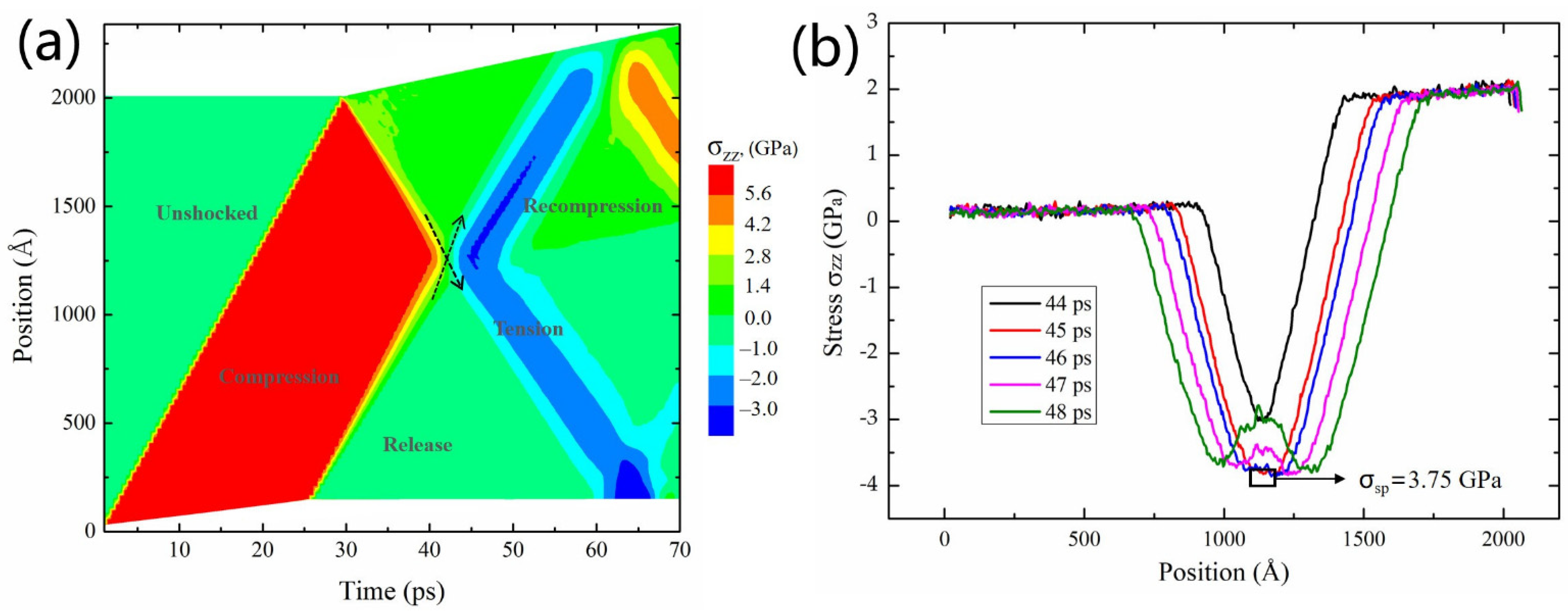
3.1. Shock Spallation

For a more intuitive understanding of the shock compression, release, tension, spall, and recompression stages, a position-time (z-t) diagram in terms of local stress, σzz, as an example, is given in Figure 1a. Under shock loading, a compressive shock wave was produced in the sample that travels towards the rear surface. At 25 ps, the unloading process began, generating a release wave from the side of piston. When the shock wave reached the rear surface (~30 ps), the rear surface expanded freely, yielding a reflected rarefaction wave. This rarefaction wave continued to propagate to the left and then interact with the tail of the release wave at about 40 ps to induce an evolving tensile region. When the tensile stress was strong enough, this interaction generated a high tri-axial tensile wave, as shown by the intersecting dashed-black arrows, which further lead to nucleation, growth, and collapse of voids, eventually forming a spall region. The peak value of the tensile stress at the spall plane is defined as the spall strength (σsp) of the material. We calculated the spall strength of each vacancy concentration system according to the maximal tensile stress during tensile. The method to determine the accurate spall strength is displayed in Figure 1b. We plotted the spatial distribution diagram of stress before and after spall damage nucleation, finding that the tensile stress reached its peak at 45 ps and the corresponding tensile stress was 3.75 GPa. This maximal tensile stress is called spall strength. The formation of spallation would induce recompression in the sample, resulting in a pullback hump in the free surface velocity history (Figure 2).
The free surface velocity history can be used to describe the various stages of spallation and measure the spall strength. Figure 2 shows the free surface velocity Vfs (t) evolution results along the two orientations at different Cv. When the shock front reaches the free surface, the free surface undergoes an acceleration from zero to about twice the velocity of the piston (Vmax ≈ 2 Vp). As the tensile state begins, the free surface velocity gradually decelerates to the first minimum value of Vfs (t). The pullback velocity ΔVfs is the difference between the maximum and the first minimum value. When the spallation occurs, the tensile stress in the damaged area suddenly drops to zero, and then a compression wave forms in the spall plane. As a result, the reverberation of stress waves causes the formation of pullback hump (spall signal).
We can find that the effect of vacancy defects on Vfs (t) is highly dependent on the crystal orientations. For the [0001] direction (Figure 2a), there was no difference in dynamic response when Cv ≤ 0.5%, and no pullback hump appeared. Spallation occurred for Cv > 0.5%, and the sharper pullback hump with increasing Cv in Vfs (t), indicating that the degree of spall damage increased gradually. However, for the [10–10] direction (Figure 2b), the unstable shock plateaus were formed during the release stage in the case of Cv > 0.5%, which means that the vacancies collapsed, and plasticity may have absorbed part of the shock energy during the previous compression stage. No spallation occurred at Cv = 0% because of its low tensile stress level. Interestingly, the pullback hump started to decline when Cv increased to 0.5%, implying a gradual decrease in the degree of spall damage.
To further explain the anisotropic effect of Cv on spall damage, some parameters of simulation results are listed in Table 1. The temperature of the spall plane, at the moment right before the incipient spall, is defined as spall temperature, Tsp. The shock temperature, TH, is gradually released to the spall temperature, Tsp, during adiabatic expansions. Vacancies collapse and plasticity can absorb part of shock energy, resulting in shock heating state. For [0001] direction, the shock stress, σzz,H, and shock temperature, TH, remain nearly constant even at Cv = 2.0%, while the spall temperature, Tsp, increases by 7.5% for Cv = 2.0% relative to Cv ≤ 1.0% due to the heating effect of tensile plasticity. It is noted that the spall strength, σsp, decreases with the increase in Tsp when Cv ≥ 1.0%, so that the spall damage is more likely to occur. However, for [10–10] direction, the σzz,H reduces by about 16% for [10–10] direction when Cv is increased to 2.0%. The stress attenuation will weaken the stress field around the spallation region, making it difficult to achieve the tensile stress required for void nucleation, so that the spall damage no longer easily occurs. Obviously, it is reasonable that the spall damage would reduce at higher Cv for the [10–10] direction. Therefore, spallation damage may be determined by the competition mechanism between energy absorption and stress attenuation generated by plasticity.

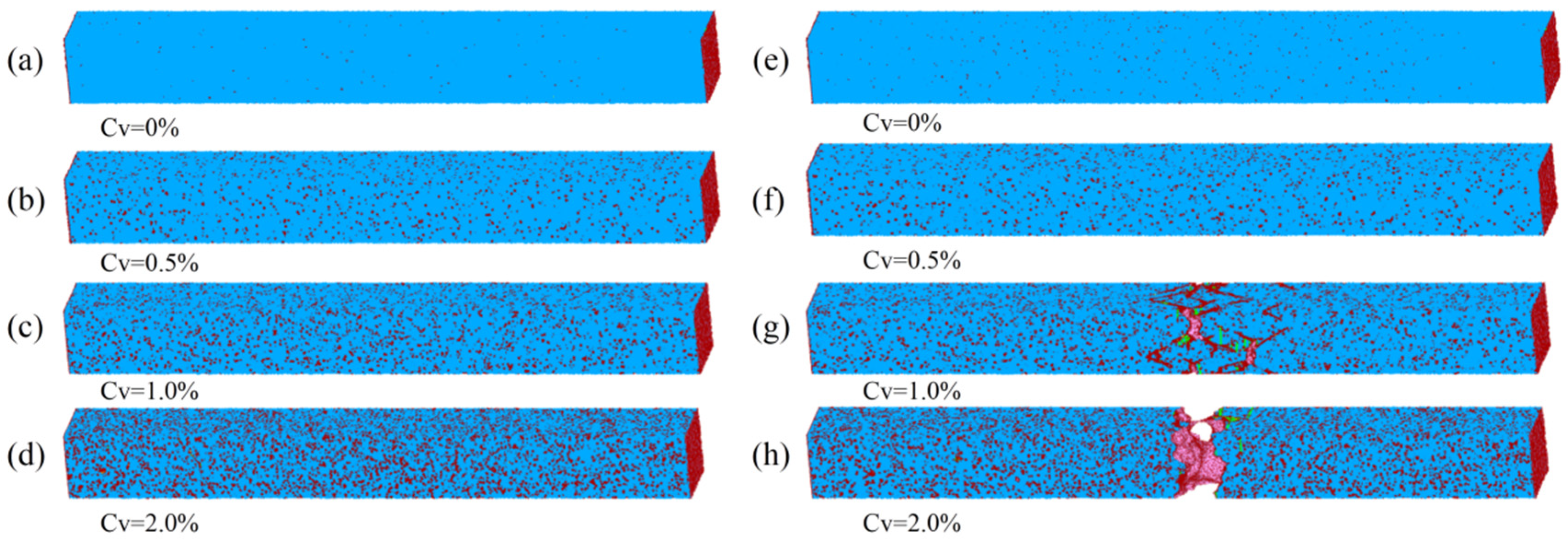
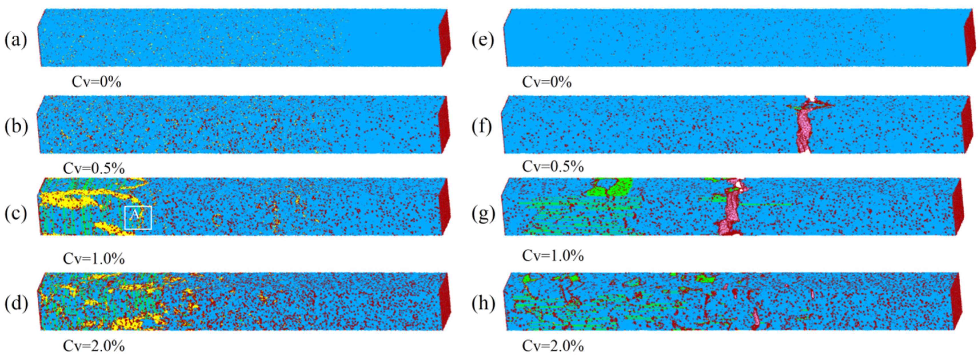
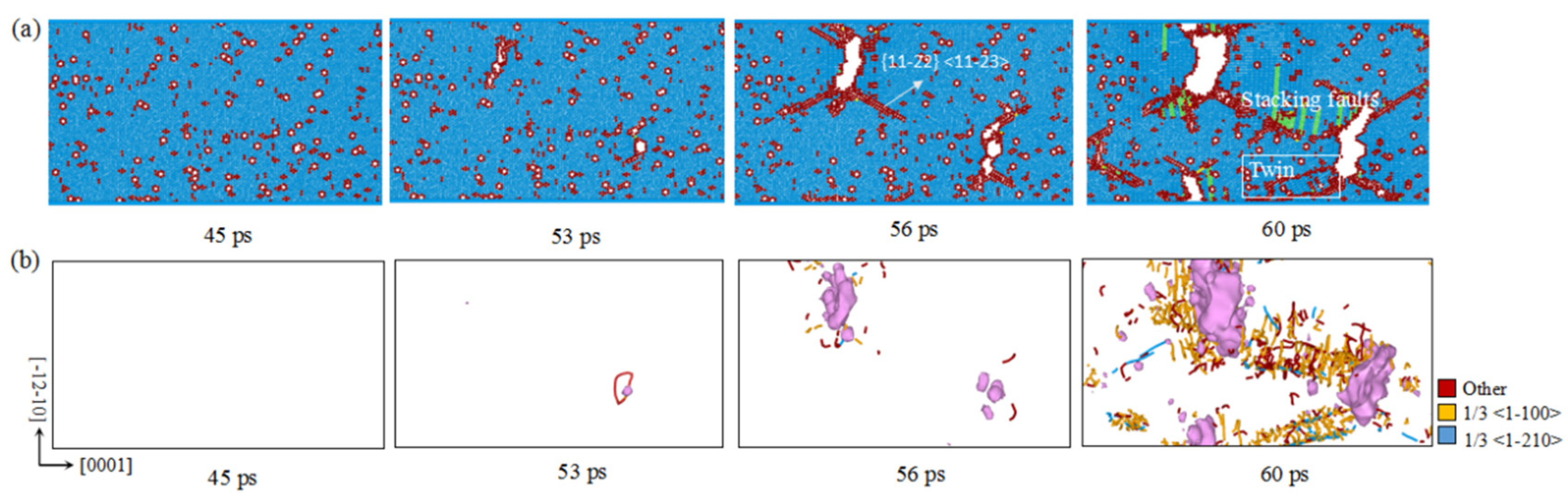
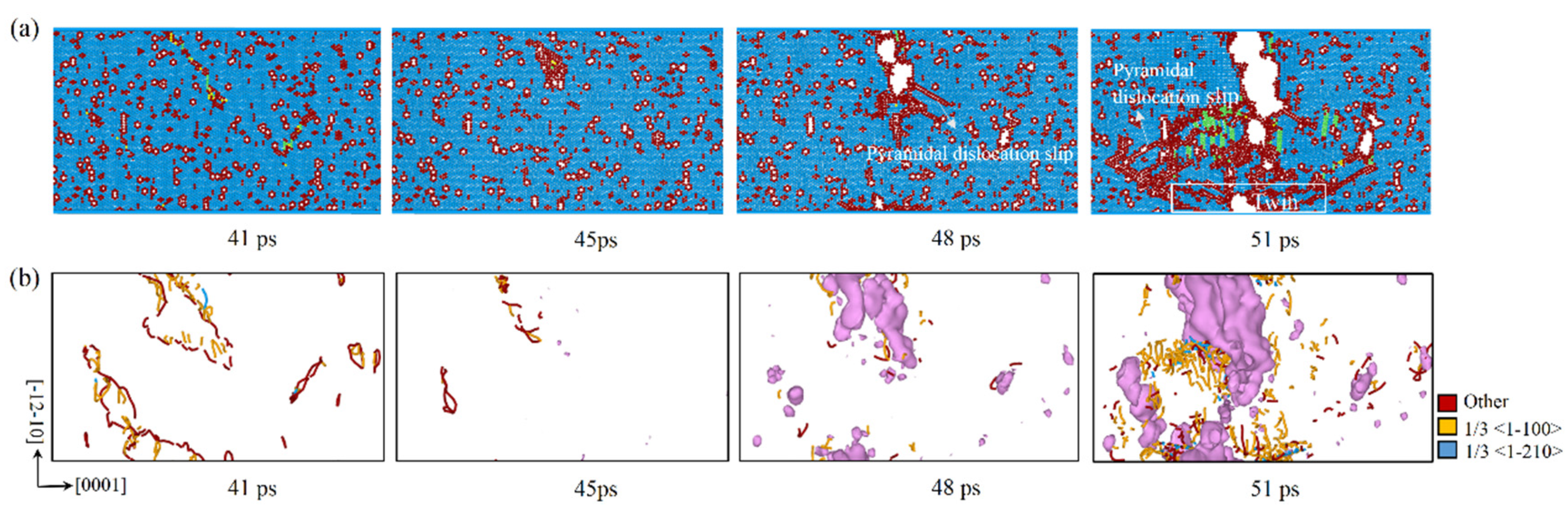
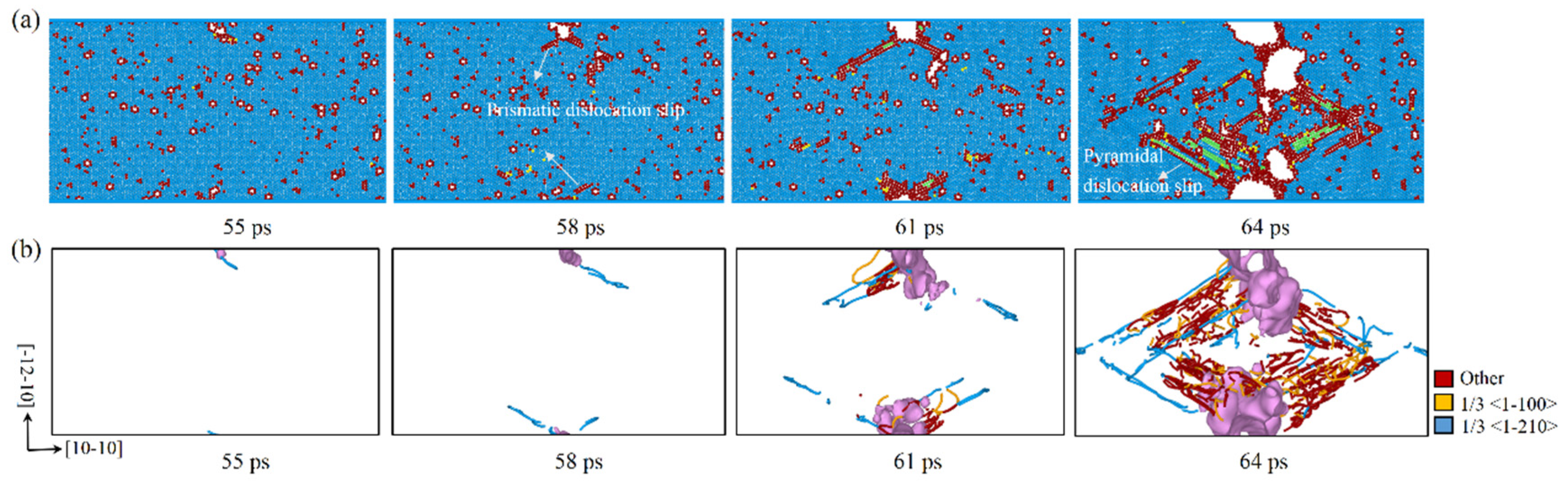
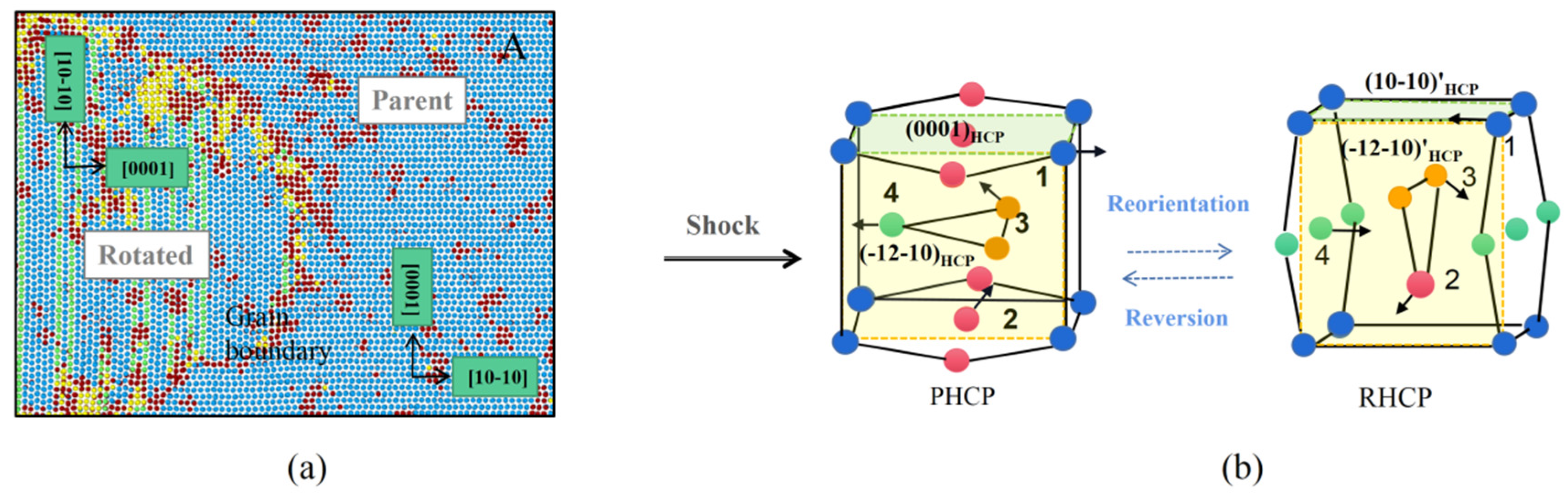
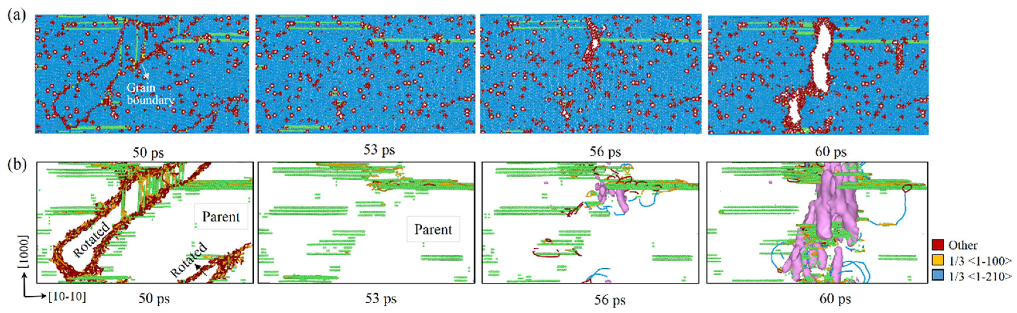
3.2. Microstructures under Compression and Tension

Vacancies have an appreciable effect on the plasticity and spall damage of single-crystal Mg if Cv is above a critical value, and the effects highly depend on the shock loading direction, as shown by Figure 3 and Figure 4. For shock along the [0001] direction, only elastic deformation occurred during compression for Cv ≤ 1.0% (Figure 3a–c). When Cv = 2.0% (Figure 3d), a small number of partial dislocations nucleated and propagated in the compression region of the sample. During tension, no spallation occurred at Cv ≤ 0.5%. However, it is interesting that spallation still occurred at Cv = 1.0% despite the absence of compression plasticity, which also occurred in the direction of [10–10] with Cv = 0.5% (Figure 4b,f). This phenomenon is same as that in Cu [19,20] and Ni [21], implying that tension plasticity plays a key role in spall damage. For shock along the [10–10] direction, severe plastic deformation was found in the sample of Cv ≥ 1.0% (Figure 4c,d) under compression, which mainly manifested as crystallographic reorientation, phase transition, stacking faults, and slips. The compression-induced plasticity will be partially or completely reversed during the release process, and plays an important role in the subsequent damage development. During tension, spallation occurred at Cv ≥ 0.5% (Figure 4f,h), and the degree of spall damage decreased with the increase in Cv, which is consistent with the degree of spall damage obtained from the evolution history of free surface velocity.
As we all know, the fracture mechanism of spall fracture in ductile metals is dominated by nucleation, growth, and coalescence of voids [40,41]. Figure 5 and Figure 6 display the void evolution of magnesium with different Cv shocked along the [0001] direction. In order to identify the dislocations, the DXA was applied to track the trajectories of dislocation slip. For sample with Cv = 1.0%, the plastic deformation process at the initial spallation stage manifested in the pattern of the nucleation, growth, and multiplication of dislocation emitted out from vacancy region, as shown in Figure 5. The local tensile stress reached the maximum value at 45 ps. However, it is not until 53 ps that we clearly observed the formation of the vacancy cluster defects. Meanwhile, 2 leading partial dislocations (1/6 [0–22–3] and 1/3 [–1100]) were emitted from the vacancy region, which can coordinate the deformation in the C-axis direction. The slip of dislocations merged the surrounding vacancies to form a strip-like vacancy cluster defect microstructure. Subsequently, the generated vacancy cluster defect microstructure collapsed and eventually formed a void at about 56 ps. As the dislocation slipped, {11–22} <11–23> shear bands formed at the edges of void, and the void propagated along the direction of the shear bands. Basal stacking faults are observed near the shear bands with the slip of 1/3 <1–100> partial dislocations to accommodate the plastic strain. Due to the limited number of slip systems in the HCP structure, twinning deformation plays a crucial role in the plastic deformation of Mg [42]. At 60 ps, {11–21} <–1–126> twin appeared at the bottom left of the void. It may be that the prismatic and pyramidal slips are suppressed by periodic boundary conditions, and only twinning deformation is available near the voids [29]. The voids grow slowly due to the formation of the twinning which moves with the void tip. Therefore, it is difficult for the macroscopic fracture to occur.
For the sample with Cv = 2.0% (Figure 6), the plastic deformation pattern at the initial spallation stage was similar to the sample with Cv = 1.0%, with some key differences. At about 41 ps, the reflected wave and the compression wave met, and then the compression-induced plasticity gradually disappeared during tension. When the local tensile stress reached the maximum value at 45 ps, we observed that the tensile dislocations were emitted from the residual compression plasticity region. It means that the compression-induced plasticity has a significant effect on the nucleation sites of voids. Because of the weakening effects of local plastic deformation, the void formed early and its distribution was relatively concentrated for the sample with Cv = 2.0%, so the macroscopic fracture occurred easily.
Figure 7 displays the void evolution of magnesium with Cv = 0.5% shocked along the [10–10] direction. Similar to the [0001] direction with Cv = 1.0%, the dislocation nucleated preferentially at the vacancy cluster defects, and then the vacancy cluster defect microstructure collapsed to form a void. Due to the dislocation emission caused by the activation of two prismatic slip systems {1–100} <11–20>, the void was significantly blunted and almost stopped growing after a small amount of expansion. This phenomenon is similar to the simulation results of Tang et al. [29]. Subsequently, new voids were generated in the vacancies with the prismatic dislocation emissions at about 61 ps. Since the activation of prismatic slip systems were insufficient to release the concentrated stress, the dislocations in the basal and pyramidal planes near the voids were activated, as shown at 64 ps, followed by stacking faults. The nucleation and emission of dislocations eventually achieved the growth and coalescence of the voids.
For the samples with Cv = 1.0% loading along the [10–10] direction, crystallographic reorientation was the main plastic deformation mode during shock compression. We described the reorientation in more detail by selecting a representative region of the sample with Cv = 1.0%, as shown in Figure 8a. Crystallographic reorientation occurred around the [–12–10] orientation with a rotation angle of 90°, and the basal stacking fault appeared in the rotated region. The mechanism is discussed relatively clearly in a qualitative manner, displayed in Figure 8b. Similar to the atomic rearrangement of HCP single crystals, such as Mg [43,44,45], under the compression experiment and simulation, and Ti [46] under impact loading, the rotation was the result of a shear and shuffle mechanism. However, the lattice reorientation is reversible, and returned to the parent lattice gradually after unloading. In Figure 9, at 50 ps, the rotated lattice in the spall region gradually recovered to the parent lattice, and stacking faults can be observed on both sides of the grain boundary. When the tensile stress reached the maximum value at 53 ps, only the parent lattice exists in the spall region. There were intensive defects in the region of basal stacking faults interaction, which made the voids nucleate rapidly along the faults at a lower tension stress. As in the sample with Cv = 0.5%, voids nucleation and growth were accompanied by the emission of {1–100} <11–20> prismatic dislocations, so the void shapes were non-spherical for shock along the [10–10] direction. Basal and pyramidal dislocations around the void were also activated, but the density was much lower than that in the sample with Cv = 0.5%. The reason is that the rapid growth of the voids greatly released the concentrated stress in the spall region. In addition, no twinning was observed in any simulations along the [10–10] direction.
By visualization, dislocation emission, void nucleation, and coalescence of voids and micro-cavities lead to the formation of spall plane. Void nucleates at vacancies, and compressive plasticity has an important effect on void nucleation sites.

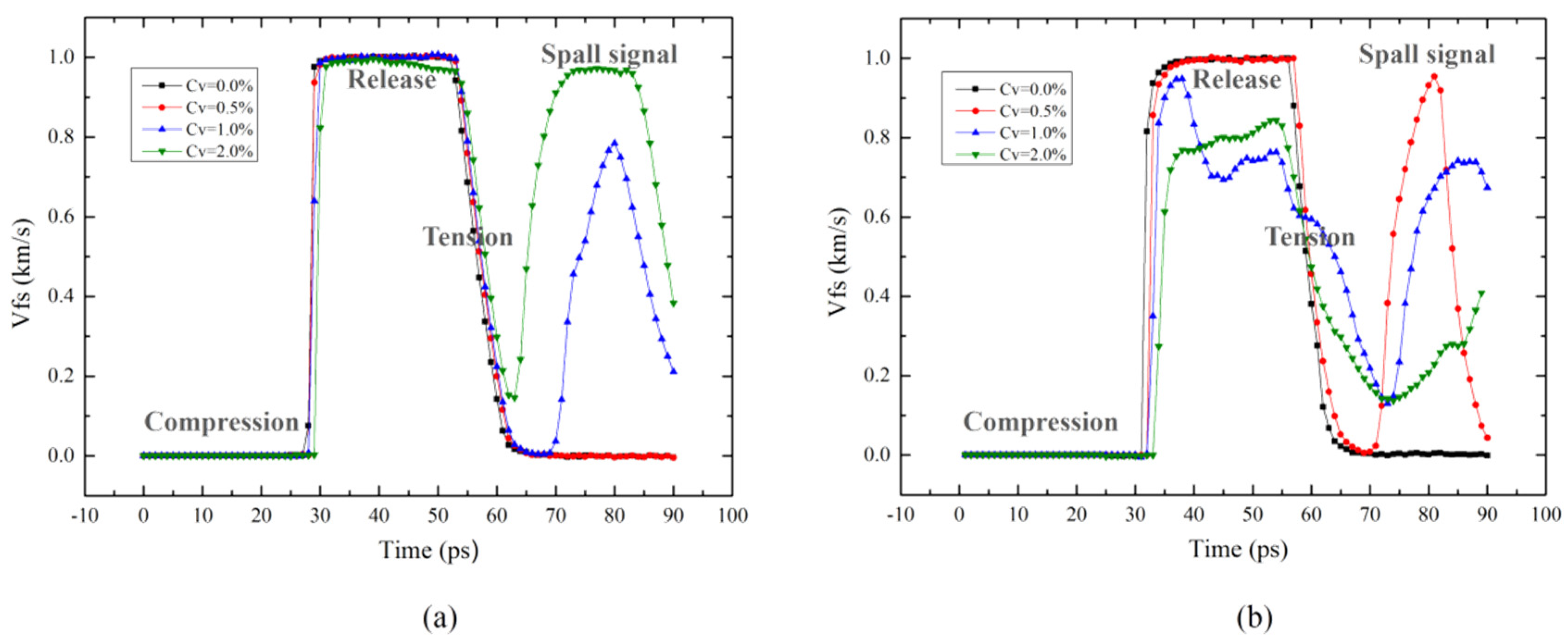
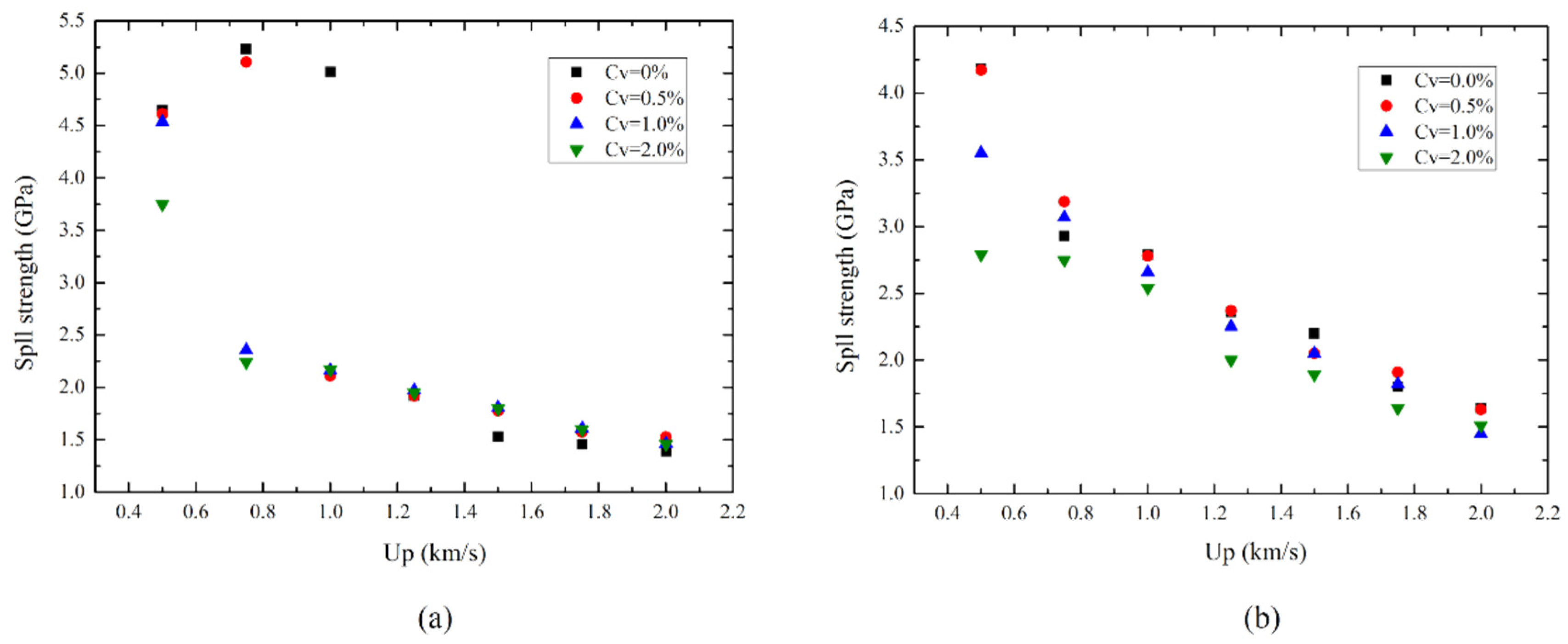
3.3. Effect of Shock Velocity on Spall Strength

The spall strength is an important parameter for estimating the resistance to spall damage in a metal. In this work, the effect of vacancies on spall strength of single-crystal magnesium at different shock velocity Vp was also investigated, and the results are shown in Figure 10a,b. For both the [0001] and [10–10] directions, σsp generally decreased with the increase in Vp, which was consistent with Agarwal’s MD results [14]. However, the pre-existence of vacancies further reduced the σsp of single-crystal Mg, making the spall occur at a lower level of tension stress. It is well known that the wave structure is a single elastic wave when a given loading strength is lower than the Hugoniot elastic limit (HEL) of a perfect single crystal [14]. In this work, the Hugoniot elastic limit velocities (VpHEL) of perfect single-crystalline Mg in the [0001] direction and the [10–10] direction were about 1.1 km/s and 0.6 km/s, respectively. Vacancy defects promoted the nucleation of compression plasticity, which made the VpHEL in the defective sample lower than that in perfect single crystal. It can be found that when the impact velocity is slightly greater than VpHEL, the spall strength decreases significantly. This means that the plastic deformation in the compression stage has a significant effect on σsp. For the [0001] direction, vacancy defects were found to have negligible effect on the spall strength of single-crystal Mg at higher shock velocity (Vp ≥ 1.0 km/s). A similar trend can also be observed in Li’s simulations for small size void magnesium [28]. Experimentally, the values of σsp for magnesium and magnesium alloys reported were generally in the range of 1–2 GPa [2,47,48,49,50], and the values were higher in the direction of [10–10] than that in the direction of [0001]. Our simulation results are close to the experimental results at higher shock velocities. Moreover, it can be observed that the fracture toughness of magnesium metal is much lower than that of BCC or FCC metals, owing to the very limited slip systems available for dislocation glide.
Consequently, the effect of vacancy defects on plastic deformation and spallation response was found to be anisotropic. Since the [10–10] direction had the lowest activated slip system, the effect of vacancy defects can be expected to be most significant in this direction.

4. Conclusions

Molecular dynamics simulations are used to study the effect of vacancies on dynamic response and spallation in single-crystal magnesium in the shock directions [0001] and [10–10]. The mechanisms of plastic deformation, spall damage, and void evolution of single-crystal magnesium with various vacancy concentrations are investigated. The main findings are summarized as follows.
Vacancies provide nucleation sites for plasticity, and the increasing vacancy concentration greatly promotes the heterogeneous nucleation of plasticity. Our research shows that the plastic deformation is various for different loading directions. The shock compression stage exhibits the deformation modes of crystallographic reorientation, phase transition, stacking faults, and slips when Cv is above a critical value. The crystallographic reorientation can only take place in samples loaded along the [10–10] direction. Under tension, the basal, prismatic, and pyramidal slips occur at the spallation region and are responsible for the plasticity deformation. The compression plasticity has a significant effect on the nucleation sites, while the tensile plasticity plays a key role in the evolution of void shape.
Vacancy collapse and subsequent plastic deformation mainly result in two competing mechanisms—energy absorption and stress attenuation. For the [0001] direction, energy absorption dominates, so the degree of spall damage increases with the increase in Cv. For the [10–10] direction, when Cv ≥ 0.5%, stress attenuation dominates, so the degree of spall damage decreases with the increase in Cv. Whether spallation damage occurs or not, eventually depends on the competition between the two mechanisms.
By visualizing the evolution of spallation, we found that the voids usually nucleate at defects, and the void evolution is mainly based on the emission mechanism of dislocations. The {11–22} <11–23> pyramidal dislocation facilitates the nucleation of void in the [0001] shock direction, as well as the {1–100} <11–20> prismatic dislocation in the [10–10] shock direction. In addition, the {11–21} <–1–126> tensile twin is observed near the voids in the orientation of [0001], and no tensile twin participates in the deformation of the [10–10] direction.

Author Contributions

C.J. and Z.J. concept this work; C.J. performs simulations, collects data, analyzes data and writes the original draft; all authors analyze results; X.L. and S.X. contribute to writing–review and editing manuscript. All authors have read and agreed to the published version of the manuscript.

Funding

This work was financially supported by the National Natural Science Foundation of China (NSFC 51871095, 51871094, NSFC-NSAF U1830138), Natural Science Foundation of Hunan Province (No. 2018JJ2036).

Institutional Review Board Statement

Not applicable.

Informed Consent Statement

Not applicable.

Data Availability Statement

Data supporting reported results can be found in this paper.

Acknowledgments

The authors would like to acknowledge the support of the computation platform of the National Super-Computer Center in Changsha (NSCC).

Conflicts of Interest

The authors declare no conflict of interest.

References

  1. Xie, P.C.; Wang, Y.G.; Shi, T.Y.; Wang, X.F.; Hu, C.M.; Hu, J.B.; Zhang, F.G. Damage evolution and spall failure in copper under complex shockwave loading conditions. J. Appl. Phys. 2020, 128, 055111. [Google Scholar] [CrossRef]
  2. Kanel, G.I.; Garkushin, G.V.; Savinykh, A.S.; Razorenov, S.V.; de Resseguier, T.; Proud, W.G.; Tyutin, M.R. Shock response of magnesium single crystals at normal and elevated temperatures. J. Appl. Phys. 2014, 116, 143504. [Google Scholar] [CrossRef]
  3. Wang, Y.G.; Qi, M.L.; He, H.L.; Wang, L.L. Spall failure of aluminum materials with different microstructures. Mech. Mater. 2014, 69, 270–279. [Google Scholar] [CrossRef]
  4. Lescoute, E.; De Rességuier, T.; Chevalier, J.-M.; Loison, D.; Cuq-Lelandais, J.-P.; Boustie, M.; Breil, J.; Maire, P.-H.; Schurtz, G. Ejection of spalled layers from laser shockloaded metals. J. Appl. Phys. 2010, 108, 093510. [Google Scholar] [CrossRef]
  5. Jarmakani, H.; Maddox, B.; Wei, C.T.; Kalantar, D.; Meyers, M.A. Laser shock-induced spalling and fragmentation in vanadium. Acta Mater. 2010, 58, 4604–4628. [Google Scholar] [CrossRef]
  6. de Rességuier, T.; Hemery, S.; Lescoute, E.; Villechaise, P.; Kanel, G.I.; Razorenov, S.V. Spall fracture and twinning in laser shock-loaded single-crystal magnesium. J. Appl. Phys. 2017, 121, 165104. [Google Scholar] [CrossRef]
  7. Kanel, G.I. Spall fracture: Methodological aspects, mechanisms and governing factors. Int. J. Fract. 2010, 163, 173–191. [Google Scholar] [CrossRef]
  8. Wang, X.X.; He, A.M.; Zhou, T.T.; Wang, P. Spall damage in single crystal tin under shock wave loading: A molecular dynamics simulation. Mech. Mater. 2021, 160, 103991. [Google Scholar] [CrossRef]
  9. Srinivasan, S.G.; Baskes, M.I. Atomistic simulations of shock induced microstructural evolution and spallation in single crystal nickel. J. Appl. Phys. 2007, 101, 043504. [Google Scholar] [CrossRef]
  10. Luo, S.N.; Germann, T.C.; Tonks, D.L. Spall damage of copper under supported and decaying shock loading. J. Appl. Phys. 2009, 106, 123518. [Google Scholar] [CrossRef]
  11. Gunkelmann, N.; Bringa, E.M.; Urbassek, H.M. Influence of phase transition on shock-induced spallation in nanocrystalline iron. J. Appl. Phys. 2015, 118, 185902. [Google Scholar] [CrossRef]
  12. Chen, J.; Tschopp, M.A.; Dongare, A.M. Shock wave propagation and spall failure of nanocrystalline Cu/Ta alloys: Effect of Ta in solid-solution. J. Appl. Phys. 2017, 122, 225901. [Google Scholar] [CrossRef]
  13. Chen, J.; Hahn, E.N.; Dongare, A.M.; Fensin, S.J. Understanding and predicting damage and failure at grain boundaries in BCC Ta. J. Appl. Phys. 2019, 126, 165902. [Google Scholar] [CrossRef]
  14. Agarwal, G.; Dongare, A.M. Shock wave propagation and spall failure in single crystal Mg at atomic scales. J. Appl. Phys. 2016, 119, 145901. [Google Scholar] [CrossRef]
  15. Jiang, S.; Huang, Y.F.; Wang, K.; Li, X.F.; Deng, H.Q.; Xiao, S.F.; Zhu, W.J.; Hu, W.Y. Effects of vacancies on plasticity and phase transformation in single-crystal iron under shock loading. J. Appl. Phys. 2021, 130, 015107. [Google Scholar] [CrossRef]
  16. Wang, M.; Beyerlein, I.J.; Zhang, J.; Han, W.Z. Defect-interface interactions in irradiated Cu/Ag nanocomposites. Acta Mater. 2018, 160, 211–223. [Google Scholar] [CrossRef]
  17. Fukata, N.; Kasuya, A.; Suezawa, M. Vacancy Formation Energy of Silicon Determined by a New Quenching Method. Jpn. J. Appl. Phys. 2001, 40, L854–L856. [Google Scholar] [CrossRef]
  18. Botez, C.E.; Elliott, W.C.; Miceli, P.F.; Stephens, P.W. Vacancy formation in homoepitaxially grown Ag films and its effect on surface morphology. Phys. Rev. B 2002, 66, 075418. [Google Scholar] [CrossRef] [Green Version]
  19. Luo, S.N.; Germann, T.C.; Tonks, D.L. The effect of vacancies on dynamic response of single crystal Cu to shock waves. J. Appl. Phys. 2010, 107, 056102. [Google Scholar] [CrossRef]
  20. Lin, E.Q.; Shi, H.J.; Niu, L.S. Effects of orientation and vacancy defects on the shock Hugoniot behavior and spallation of single-crystal copper. Model. Simul. Mater. Sci. Eng. 2014, 22, 035012. [Google Scholar]
  21. Qiu, T.; Xiong, Y.N.; Xiao, S.F.; Li, X.F.; Hu, W.Y.; Deng, H.Q. Non-equilibrium molecular dynamics simulations of the spallation in Ni: Effect of vacancies. Comput. Mater. Sci. 2017, 137, 273–281. [Google Scholar] [CrossRef]
  22. Pollock, T.M. Materials science. Weight loss with magnesium alloys. Science 2010, 328, 986–987. [Google Scholar] [CrossRef] [PubMed]
  23. Hazell, P.J.; Appleby-Thomas, G.J.; Wielewski, E.; Escobedo, J.P. The shock and spall response of three industrially important hexagonal close-packed metals: Magnesium, titanium and zirconium. Philos. Trans. R. Soc. A 2014, 372, 20130204. [Google Scholar] [CrossRef]
  24. Chen, J.; Tan, L.; Yu, X.; Etim, I.P.; Ibrahim, M.; Yang, K. Mechanical properties of magnesium alloys for medical application: A review. J. Mech. Behav. Biomed. Mater. 2018, 87, 68–79. [Google Scholar] [CrossRef]
  25. Aghababaei, R.; Joshi, S.P. Micromechanics of tensile twinning in magnesium gleaned from molecular dynamics simulations. Acta Mater. 2014, 69, 326–342. [Google Scholar] [CrossRef]
  26. Tang, T.; Kim, S.; Horstemeyer, M.F. Molecular dynamics simulations of void growth and coalescence in single crystal magnesium. Acta Mater. 2010, 58, 4742–4759. [Google Scholar] [CrossRef]
  27. Xu, S.; Su, Y.; Chavoshi, S.Z. Deformation of periodic nanovoid structures in Mg single crystals. Mater. Res. Exp. 2018, 5, 016523. [Google Scholar] [CrossRef] [Green Version]
  28. Li, G.; Wang, Y.; Xiang, M.; Liao, Y.; Wang, K.; Chen, J. Shock response of nanoporous magnesium by molecular dynamics simulations. Int. J. Mech. Sci. 2018, 141, 143–156. [Google Scholar] [CrossRef]
  29. Tang, T.; Kim, S.; Horstemeyer, M.F. Fatigue crack growth in magnesium single crystals under cyclic loading: Molecular dynamics simulation. Comput. Mater. Sci. 2010, 48, 426–439. [Google Scholar] [CrossRef]
  30. Wang, J.; Beyerlein, I.J.; Tomé, C.N. Reactions of lattice dislocations with grain boundaries in Mg: Implications on the micro scale from atomic-scale calculations. Int. J. Plast. 2014, 56, 156–172. [Google Scholar] [CrossRef]
  31. Mei, H.; Xu, S.; Liu, L.; She, W.; Li, J.; Fu, Z. Effect of twin boundary on the initial yield behavior of magnesium nanopillars under compression: Molecular dynamics simulations. Mater. Res. Exp. 2018, 5, 026513. [Google Scholar] [CrossRef]
  32. Jahanshahi, M.; Khoei, A.R.; Heidarzadeh, N.; Jafarian, N. A hierarchical thermo-mechanical multi-scale technique for modeling of edge dislocations in nano-crystalline structures. Comput. Mater. Sci. 2018, 141, 360–374. [Google Scholar] [CrossRef]
  33. Plimpton, S. Fast Parallel Algorithms for Short-Range Molecular Dynamics. J. Comput. Phys. 1995, 117, 1–19. [Google Scholar] [CrossRef] [Green Version]
  34. Jian, Z.Y.; Chen, Y.C.; Xiao, S.F.; Wang, L.; Li, X.F.; Wang, K.; Deng, H.Q.; Hu, W.Y. Shock-induced plasticity and phase transformation in single crystal magnesium: An interatomic potential and non-equilibrium molecular dynamics simulations. J. Phys. Condens. Matter 2022, 34, 115401. [Google Scholar] [CrossRef] [PubMed]
  35. Wang, K.; Zhang, F.G.; He, A.M.; Wang, P. An atomic view on spall responses of release melted lead induced by decaying shock loading. J. Appl. Phys. 2019, 125, 155107. [Google Scholar] [CrossRef]
  36. Stukowski, A. Structure identification methods for atomistic simulations of crystalline materials. Model. Simul. Mater. Sci. Eng. 2012, 20, 045021. [Google Scholar] [CrossRef]
  37. Stukowski, A. Visualization and analysis of atomistic simulation data with OVITO–the Open Visualization Tool. Model. Simul. Mater. Sci. Eng. 2010, 18, 015012. [Google Scholar] [CrossRef]
  38. Stukowski, A.; Bulatov, V.V.; Arsenlis, A. Automated identification and indexing of dislocations in crystal interfaces. Model. Simul. Mater. Sci. Eng. 2012, 20, 085007. [Google Scholar] [CrossRef]
  39. Xiang, M.Z.; Hu, H.B.; Chen, J.; Long, Y. Molecular dynamics simulations of micro-spallation of single crystal lead. Model. Simul. Mater. Sci. Eng. 2013, 21, 055005. [Google Scholar] [CrossRef]
  40. Molinari, A.; Wright, T.W. A physical model for nucleation and early growth of voids in ductile materials under dynamic loading. J. Mech. Phys. Solids 2005, 53, 1476–1504. [Google Scholar] [CrossRef]
  41. Antoun, T.; Seaman, L.; Curran, D.R.; Kanel, G.I.; Razorenov, S.V.; Utkin, A.V. Spall Fracture; Springer: New York, NY, USA, 2010. [Google Scholar]
  42. Partridge, P.G.; Roberts, E. The formation and behaviour of incoherent twin boundaries in hexagonal metals. Acta Metall. 1964, 12, 1205–1210. [Google Scholar] [CrossRef]
  43. Liu, B.Y.; Wang, J.; Li, B.; Lu, L.; Zhang, X.Y.; Shan, Z.W.; Li, J.; Jia, C.L.; Sun, J.; Ma, E. Twinning-like lattice reorientation without a crystallographic twinning plane. Nat. Commun. 2014, 5, 4297. [Google Scholar] [CrossRef] [PubMed] [Green Version]
  44. Liu, B.Y.; Wan, L.; Wang, J.; Ma, E.; Shan, Z.W. Terrace-like morphology of the boundary created through basal-prismatic transformation in magnesium. Scr. Mater. 2015, 100, 86–89. [Google Scholar] [CrossRef] [Green Version]
  45. Jian, Z.Y.; Chen, Y.C.; Xiao, S.F.; Wang, L.; Li, X.F.; Wang, K.; Deng, H.Q.; Hu, W.Y. Molecular dynamic simulations of plasticity and phase transition in Mg polycrystalline under shock compression. Appl. Phys. Express 2022, 15, 015503. [Google Scholar] [CrossRef]
  46. Zong, H.X.; Lookman, T.; Ding, X.D.; Luo, S.N.; Sun, J. Anisotropic shock response of titanium: Reorientation and transformation mechanisms. Acta Mater. 2014, 65, 10–18. [Google Scholar] [CrossRef]
  47. Garkushin, G.V.; Savinykh, A.S.; Kanel, G.I.; Razorenov, S.V.; Jones, D.; Proud, W.G.; Botvina, L.R. Response of magnesium single crystals to shockwave loading at room and elevated temperatures. J. Phys. Conf. Ser. 2014, 500, 112027. [Google Scholar] [CrossRef] [Green Version]
  48. Hazell, P.J.; Appleby-Thomas, G.J.; Wielewski, E.; Stennett, C.; Siviour, C. The influence of microstructure on the shock and spall behaviour of the magnesium alloy, Elektron 675. Acta Mater. 2012, 60, 6042–6050. [Google Scholar] [CrossRef]
  49. Kanel, G.I.; Razoreno, S.V.; Bogatch, A.; Utkin, A.V.; Fortov, V.E.; Grady, D.E. Spall fracture properties of aluminum and magnesium at high temperatures. J. Appl. Phys. 1996, 79, 8310–8317. [Google Scholar] [CrossRef]
  50. Winey, J.M.; Renganathan, P.; Gupta, Y.M. Shock wave compression and release of hexagonal-close-packed metal single crystals: Inelastic deformation of c-axis magnesium. J. Appl. Phys. 2015, 117, 105903. [Google Scholar] [CrossRef]
Figure 1. (a) Contour plot of evolution of stress (σzz) as a function of time along the [0001] direction with Cv = 2.0% under Vp = 0.5 km/s. The colors are colored by local stress, a positive value corresponds to compressive stress, and a negative value corresponds to tensile stress. (b) The corresponding spatial distributions of stress (σzz) before and after nucleation of spall damage.
Metals 12 00215 g001
Figure 2. Free surface velocity evolution history with different Cv along different shock directions: (a) [0001] and (b) [10–10] under Vp = 0.5 km/s.
Metals 12 00215 g002
Figure 3. Atomic configurations for single-crystal magnesium with Cv = 0%, 0.5%, 1.0%, and 2.0% during shock compression (ad) at 20 ps and during tension (eh) at 60 ps impacted along the [0001] direction under Vp = 0.5 km/s. Atoms are colored by CNA values, red atoms correspond to vacancies as well as disordered atoms, blue and yellow atoms correspond to the HCP structure and BCC structure, respectively, while the green atoms correspond to stacking faults (FCC structure), and the pink atoms represent the surface of void (the following atomic colors represent the same structure).
Metals 12 00215 g003
Figure 4. Atomic configurations for single-crystal magnesium with Cv = 0%, 0.5%, 1.0%, and 2.0% during shock compression (ad) at 20 ps and during tension (eh) at 65 ps impacted along the [10-10] direction under Vp = 0.5 km/s.
Metals 12 00215 g004
Figure 5. Void evolution of the sample with Cv = 1.0% at different time points during initial spallation loading along the [0001] direction. (a) Atomic configurations of a chosen section of the spall region. (b) Mechanism of void growth based on dislocation emission is analyzed using DXA: 1/3 <1–100> partial basal dislocations, 1/3 <1–210> partial prismatic dislocations, other dislocations (mainly 1/6 <20–23> and 1/9 <01–13> partial dislocations), etc., are presented.
Metals 12 00215 g005
Figure 6. Void evolution of the sample with Cv = 2.0% at different time points during initial spallation loading along the [0001] direction. (a) Atomic configurations of a chosen section of the spall region. (b) Mechanism of void growth based on dislocation emission is analyzed using DXA: 1/3 <1–100> partial basal dislocations, 1/3 <1–210> partial prismatic dislocations, other dislocations (mainly 1/6 <20–23> and 1/9 <01–13> partial dislocations), etc., are presented.
Metals 12 00215 g006
Figure 7. Void evolution of the sample with Cv = 0.5% at different time points during initial spallation loading along the [10–10] direction. (a) Atomic configurations of a chosen section of the spall region. (b) Mechanism of void growth based on dislocation emission is analyzed using DXA: 1/3 <1–100> partial basal dislocations, 1/3 <1–210> partial prismatic dislocations, other dislocations (mainly 1/6 <20–23> and 1/9 <01–13> partial dislocations), etc., are presented.
Metals 12 00215 g007
Figure 8. (a) Atomic configurations in the A region of the sample with Cv = 1.0% loading along the [10–10] direction. (b) Schematic illustration of the reorientation mechanism from parent HCP (PHCP) structure to rotated HCP (RHCP) structure via atomic shuffling and rearrangement. The possible route of the atomic rearrangement is indicated by the arrow, with atoms of each color representing the same direction of motion.
Metals 12 00215 g008
Figure 9. Void evolution of the sample with Cv = 1.0% at different time points during initial spallation loading along the [10-10] direction. (a) Atomic configurations of a chosen section of the spall region. (b) Mechanism of void growth based on dislocation emission is analyzed using DXA: 1/3 <1–100> partial basal dislocations, 1/3 <1–210> partial prismatic dislocations, other dislocations (mainly 1/6 <20–23> and 1/9 <01–13> partial dislocations), etc., are presented.
Metals 12 00215 g009
Figure 10. Variation of spall strength as a function of piston velocity impacted along different crystalline directions (a) [0001] and (b) [10–10] with different vacancy concentrations.
Metals 12 00215 g010
Table 1. Shock and spall parameters of Mg with different initial vacancy concentrations Cv (%). The steady shock or Hugoniot state is denoted by the subscript H. Values listed are the shock stress, σzz,H (GPa), the shock temperature, TH (K), the spall temperature, Tsp (K) and the spall strength, σsp (GPa).
DirectionsCvσzz,HTHTspσsp
[0001]0.07.3350265 a4.65 a
0.57.2350265 a4.61 a
1.07.23502654.53
2.07.03552853.75
[10,10]0.06.7335255 a4.18 a
0.56.63352554.17
1.06.13803003.55
2.05.64003202.79
a No spall; the minimum T and stress achieved during tension.
Publisher’s Note: MDPI stays neutral with regard to jurisdictional claims in published maps and institutional affiliations.

